

Page 1

A60 and RS12
Display & GPS
Installation Manual
Document number: 87081-1
Date: December 2006
Page 2

Trademarks and registered trademarks
Raymarine is a registered trademark of Raymarine plc.
Navionics is a registered trademark of Navionics Company, Italy.
All other product names are trademarks or registered trademarks of their
respective owners.
Contents of this handbook © Raymarine 2006
Page 3

3
Contents
Trademarks and registered trademarks ............................................ 2
Important Information .........................................................................................5
Suppression Ferrites.......................................................................... 7
Connections to Other Equipment ..................................................... 8
Chapter 1: Introduction .......................................................................................9
1.1 Selecting the Display Unit Location ........................................................ 9
1.2 What Comes in the Box ........................................................................ 10
1.3 Optional Equipment ............................................................................. 11
1.4 Unit Size ............................................................................................... 12
Chapter 2: Installing the Display Unit ..............................................................13
2.1 Mounting ............................................................................................. 13
Mounting Bracket Method.................................................................... 13
Flush Mounting..................................................................................... 14
2.2 Cable Runs............................................................................................ 15
Making the Cable Connections ............................................................. 16
Power Input Cable (R08003)................................................................. 16
Power Supply.................................................................................. 17
NMEA Cable (R08004).......................................................................... 18
GPS Cable ............................................................................................ 18
Chapter 3: Installing the GPS Antenna.............................................................19
3.1 Selecting the Mounting Location ......................................................... 19
Receiver Location ................................................................................. 19
Cabling Route ...................................................................................... 20
3.2 Mounting the Receiver ......................................................................... 20
Pole Mounting ...................................................................................... 20
Surface Mounting ................................................................................ 21
Making the Cable Connections ............................................................ 22
Chapter 4: Maintenance ....................................................................................23
4.1 Introduction ......................................................................................... 23
Servicing and Safety.............................................................................. 23
Routine Checks .................................................................................... 23
Cleaning the Display Window .............................................................. 24
Recommended Cleaning Procedure ............................................... 24
4.2 Resetting the System ............................................................................ 24
Power-on Reset .............................................................................. 24
Settings Reset ................................................................................ 25
Settings and Data Reset ................................................................. 25
4.3 Troubleshooting ................................................................................... 25
Common Problems and How to Solve Them ......................................... 26
Page 4

4 A60 Installation Manual
4.4 Upgrading the Display...........................................................................27
4.5 Technical Support .................................................................................29
Worldwide Web .................................................................................... 29
Help us to help you ............................................................................... 29
Contacting Raymarine in the US ...........................................................30
Contacting Raymarine in Europe .......................................................... 31
Appendix: Specifications ................................................................................33
A60 LCD Color Display ..........................................................................33
General ..........................................................................................33
Chartplotter Features .....................................................................34
Interfacing ......................................................................................35
RS12 GPS Antenna ...............................................................................36
Index ......................................................................................................................37
Page 5
Important Information
Intended Use
The A60 is a GPS Chartplotter display unit that can be upgraded to include
optional Fishfinder functionality.
This handbook contains important information on the installation of your A60
display and RS12 GPS Antenna. To get the best results in operation and
performance, please take the time to thoroughly read the accompanying Owner’s
Handbook.
Safety Notices
WARNING: Navigation Aid
This product is intended to be used as an aid to navigation. Its
accuracy can be affected by many factors, including equipment
failure or defect, environmental conditions and incorrect
handling or use. It is the user’s responsibility to exercise common
prudence and navigational judgement. This device should not be
relied upon as a substitute for such prudence and judgement.
5
WARNING:
This equipment must be installed in accordance with the
instructions in this manual. Failure to do so could result in poor
product performance, personal injury and/or damage to the
vessel.
WARNING:
Make sure the power supply is switched off before making any
electrical connections.
CAUTION: Global Positioning System Antenna
Do not connect or disconnect the GPS antenna from the display
unit while power is switched on as this may result in irreparable
damage.
CAUTION: Water Ingress
To prevent the ingress of water and consequent damage to the
display, ensure that the chart card door is firmly closed. This can
be confirmed by an audible click.
Product Installation
Electrical Safety
Page 6
6 A60 Installation Manual
CAUTION: CompactFlash Card Installation
When installing CompactFlash cards ensure that the card is
inserted in the correct orientation. DO NOT try to force the card
into position as this may result in irreparable damage to the card.
CAUTION: CompactFlash Card Damage
DO NOT use a metallic instrument such as a screwdriver or pliers
to help you remove a card, as this can cause irreparable damage.
TFT LCD Displays
The colors of the display may seem to vary when viewed against a colored
background or in colored light. This is a perfectly normal effect that will be seen
with all color LCD displays.
In common with all Thin Film Transistor (TFT) LCD displays, the screen may exhibit
a few (less than 5) wrongly illuminated pixels. These may appear as black pixels in
a light portion of the screen or as colored pixels in black areas.
CAUTION: To provide protection against the damaging effects of
UV light, Raymarine advises that you replace the sun cover
provided when the color LCD display is not in use.
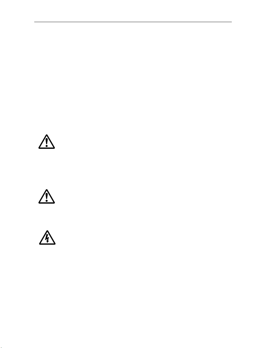
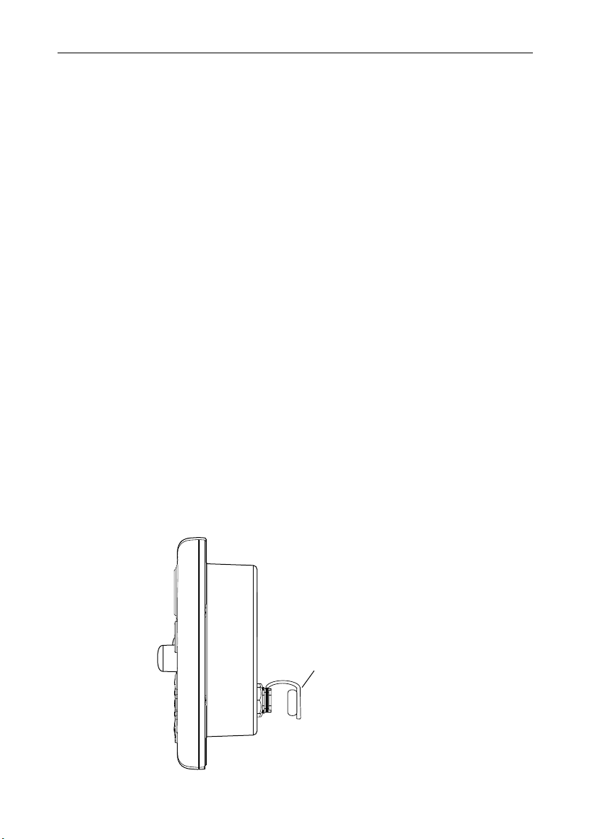
Protective Dust Covers
Protective covers have been attached on the SONAR, AUX and NMEA connectors
on the rear of the A60. If you are not using one or more of these ports, please keep
the cover attached to the connector to protect it from the elements.
Dust Cover
D8695-1
Page 7

Important Information 7
EMC Conformance
All Raymarine equipment and accessories are designed to the best industry
standards for use in the recreational marine environment.
Their design and manufacture conforms to the appropriate Electromagnetic
Compatibility (EMC) standards, but correct installation is required to ensure that
performance is not compromised. Although every effort has been taken to ensure
that they will perform under all conditions, it is important to understand what
factors could affect the operation of the product.
The guidelines given here describe the conditions for optimum EMC performance,
but it is recognized that it may not be possible to meet all of these conditions in all
situations. To ensure the best possible conditions for EMC performance within the
constraints imposed by any location, always ensure the maximum separation
possible between different items of electrical equipment.
For optimum EMC performance, it is recommended that wherever possible
Raymarine equipment and cables connected to it are:
At least 3 ft. (1 m) from any equipment transmitting or cables carrying radio
signals e.g. VHF radios, cables and antennas. In the case of SSB radios, the
distance should be increased to 7 ft. (2 m).
More than 7 ft. (2 m) from the path of a radar beam. A radar beam can normally be assumed to spread 20 degrees above and below the radiating element.
Ensure that the equipment is supplied from a separate battery from that used for
engine start. Voltage drops below 10 V, and starter motor transients, can cause
the equipment to reset. This will not damage the equipment, but may cause the
loss of some information and may change the operating mode.
Ensure that Raymarine specified cables are used. Cutting and rejoining these
cables can compromise EMC performance and must be avoided unless doing so is
detailed in the installation manual.
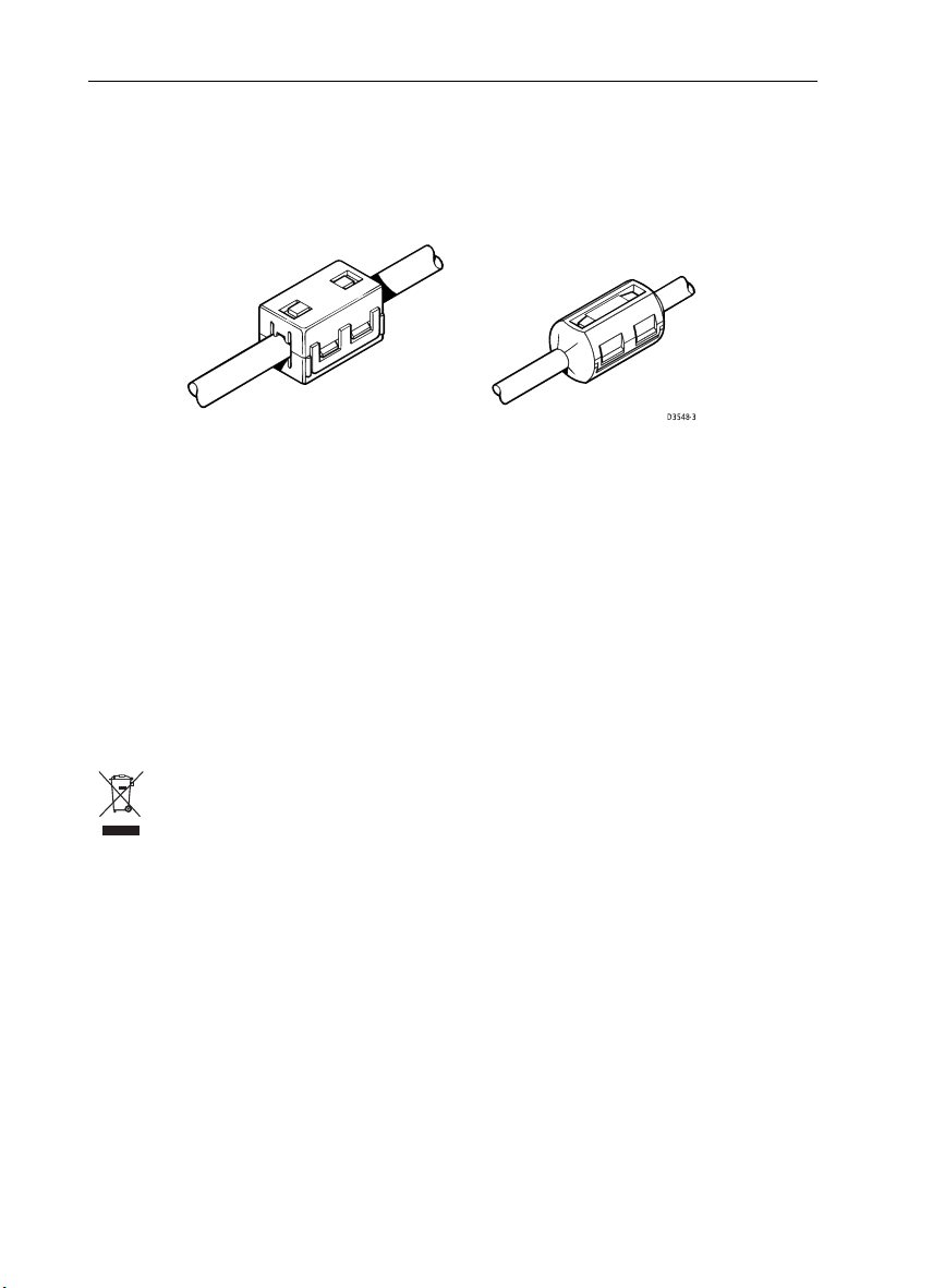
Suppression Ferrites
If a suppression ferrite is attached to a cable, this ferrite should not be removed. If
the ferrite needs to be removed during installation it must be reassembled in the
same position. If a ferrite is packed separately in the carton, it must be installed as
soon as the cables are run.
Page 8
8 A60 Installation Manual
The following illustration shows typical cable suppression ferrites sometimes
used with Raymarine equipment. To ensure EMC compliance, always use these
ferrites, if supplied by Raymarine for use with this equipment. If not supplied by
Raymarine, a ferrite is not required for use with this equipment.
D3548-3
Connections to Other Equipment
If your Raymarine equipment is to be connected to other equipment using a cable
not supplied by Raymarine, the suppression ferrite (if supplied) MUST always be
attached to the cable nearest the Raymarine unit.
Declaration of Conformity
Raymarine plc declare that the A60 Dual Function Displays are in compliance with
the essential requirements of EMC directive 2004/108/EC. The original
Declaration of Conformity certificate can be viewed on the relevant product page
at www.raymarine.com.
Product Disposal
Waste Electrical and Electronic Equipment (WEEE) Directive
The WEEE Directive requires the recycling of waste electrical and electronic
equipment. While the WEEE Directive does not apply to some of Raymarine’s
products, we support its requirements as part of our environmental policy and we
ask you to be aware of how you should dispose of this product.
The wheelie bin symbol found on our products signifies that it should not be
disposed of in general waste or landfill. Please contact your local dealer, national
distributor or Raymarine Technical Services for information on product disposal.
Page 9

Chapter 1: Introduction
This manual provides information and instructions for installing your A60 display
and RS12 GPS sensor.
1.1 Selecting the Display Unit Location
Your A60 can be mounted using the mounting bracket supplied, or console
mounted using the optional flush mount kit.
Before you install the display, plan its installation, considering:
•
Convenience. The mounting location should be easily accessible to allow
operation of the front panel controls.
•
Access. There must be sufficient space behind the display to allow cable con-
nections to the rear panel connectors, avoiding tight bends in the cable.
•
Interference. The selected location should be far enough away from devices
that may cause interference, such as motors, generators and radio transmitters/receivers (see EMC Guidelines).
•
Magnetic compass. Mount the display at least 3ft (1m) away from a mag-
netic compass.
•
Cable runs. The display should be mounted as close as possible to the DC
power source.
•
Environmental. The display should be protected from physical damage and
excessive vibration. Although the display unit is waterproof, it is good practice
to mount it in a protected area away from prolonged and direct exposure to
rain and salt spray.
9
Page 10
10 A60 Installation Manual
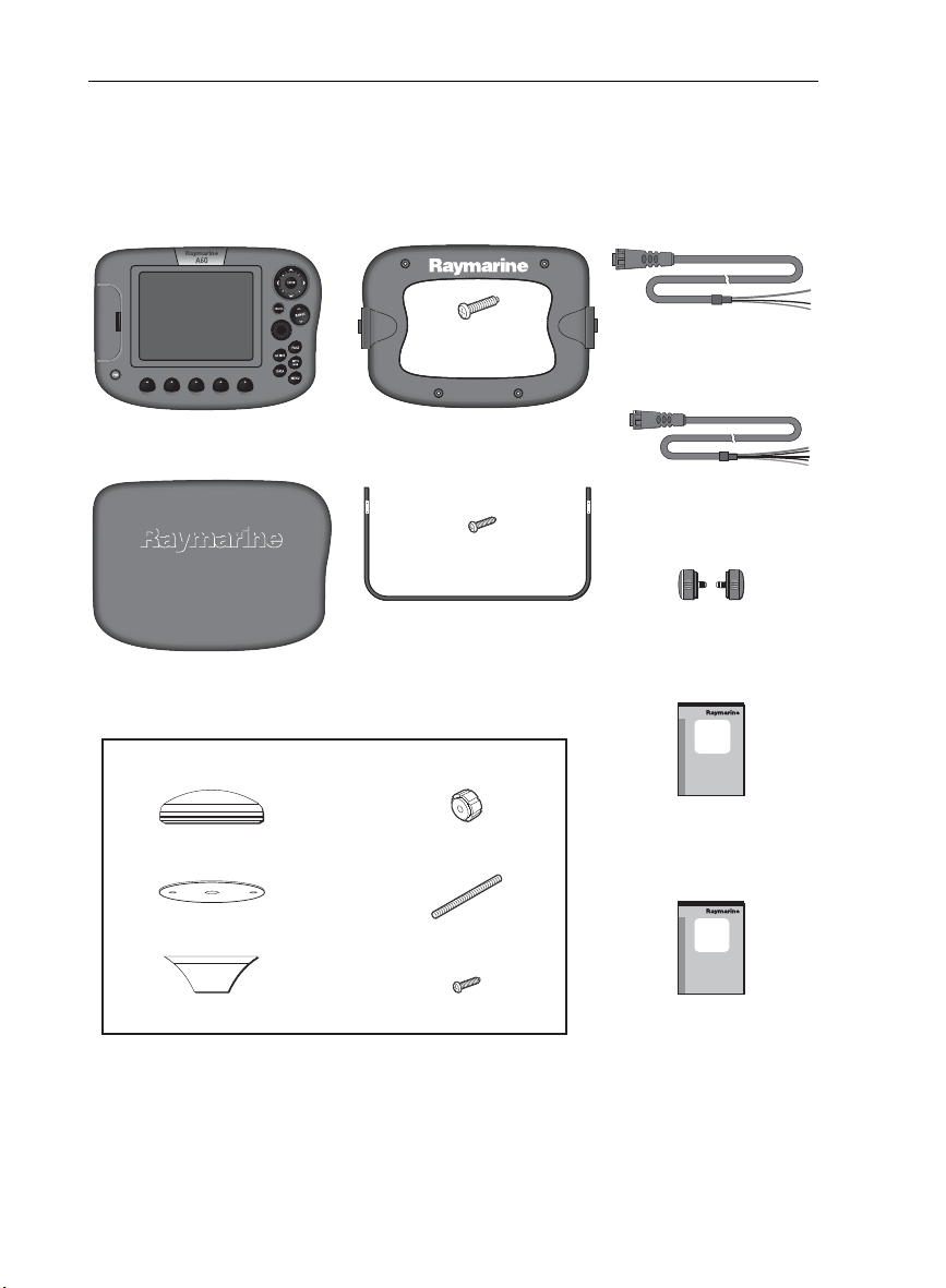
1.2 What Comes in the Box
Unpack the display carefully, to prevent damage. Save the carton and packing, in
case the unit has to be returned for service.
A60 Dual Function Display,
E33025 (US), E33026 (CE)
Sun Cover,
part no. R38108
RS12 GPS, part no. E33021
GPS Antenna
GPS Gasket
Frame Screws,
M3 (x4)
Mount Frame,
part no. R38109
Bracket Screws,
No.10 x 3/4 (x3)
Mounting Bracket,
part no. R38110
Thumb nuts (x2)
Studs (x2)
Power/Data Cable, 3 pin, 1.5m
part no. R08003
NMEA Cable, 5 pin, 1.5m
part no. R08004
Bracket Knobs,
part no. R38107
A60
Installation
Manual
Installation Manual,
part no. 87081
A60
Owner’s
Handbook
Pole Mount Bracket
Mount Screws, M4 (x2)
Owner’s Handbook,
D9613-1
part no. 81295
Page 11

Chapter 1: Introduction 11
1.3 Optional Equipment
The following optional items are also available to complete your system:
Part No. Description
E63070 DSM25, Digital Sounder Module, 200/50KHz, 500W
E36017 Flush Mount Kit, A60
R69086 Network Cable, A60, 3.5m
E36015 Network Cable, A60, 8.5m
E36016 Network Cable, A60, 15m
E66066 Transducer Adapter, Pathfinder (DSM250) to A Series
E66070 Transducer Adapter, Legacy Transducer (L365/L470) to A Series
Page 12
12 A60 Installation Manual
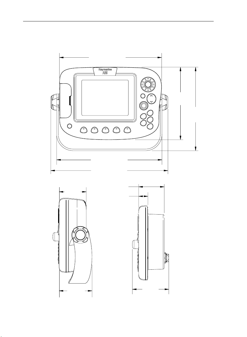
1.4 Unit Size
The dimensions for your A60 display are as follows:
9.61in (244mm)
ENTER
PWR
2.56in
(65mm)
9.88in (251mm)
11.02in (280mm)
2.40in (61mm)
.866in (22mm)
CANCEL
ACTIVE
DATA
RANGE
PAG E
WPTS
MOB
MENU
6.81in
(173mm)
7.83in
(199mm)
D9614-1
Bracket Mount
3.11in
(79mm)
3.43in
(87mm)
Flush Mount
Page 13
Chapter 2: Installing the Display Unit
The A60 display unit is waterproof to IPX-7 and can be installed either above or
below deck using either the mounting bracket or by flush mounting into the
console.
2.1 Mounting
Note:
The mounting bracket and the mount frame to which the bracket attaches must be
removed prior to flush mounting.
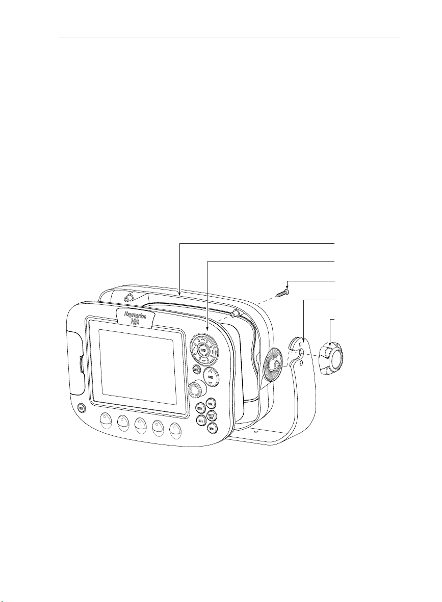
Mounting Bracket Method
The mounting bracket can be used to secure the display unit to a dash, chart table,
bulkhead or deckhead.
Mount Frame
Display Unit
Frame Screws (x4)
Mounting Bracket
Bracket Knobs (x2)
13
D9615-1
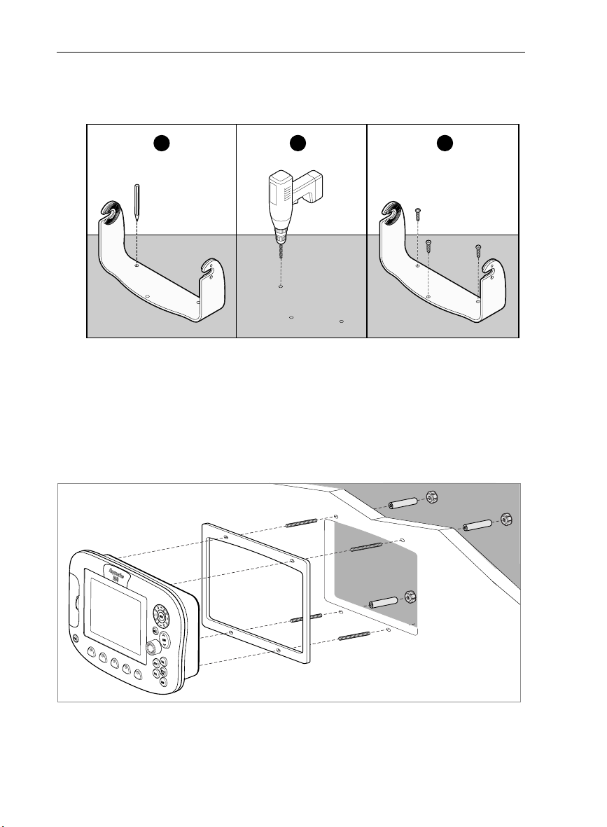
You should install the mount bracket as follows:
1. Loosen the knobs and remove the bracket from the unit.
2. Mark the locations of the bracket screw holes on the mounting surface.
3. Drill 9/64” (3mm) pilot holes at the marked locations, taking care that there
are no cables or anything that may be damaged behind the surface.
4. Align the bracket holes with the holes on the mounting surface.
Page 14
14 A60 Installation Manual
5. Use the screws and nuts supplied to securely attach the bracket to the mounting surface.
1
x3
2
3
x3
6. Attach the display unit to the bracket.
7. Adjust the unit angle for clear vision and tighten the knobs.
Flush Mounting
Flush mounting your display on the console requires the optional E36017 Flush
Mount Kit.
D7899-1
D9616-1
Page 15

Chapter 2: Installing the Display Unit 15
CAUTION: Installation
Make sure there are no hidden electrical wires or other
items behind the selected location before proceeding.
Make sure there is sufficient rear access for mounting
and cabling.
1. Check the selected location for the unit. A clear, flat area with suitable clearance behind the panel, is required.
2. Attach the template included with the flush mount kit to the selected location, using masking or self-adhesive tape, taking care that it is level.
3. Use a hole saw to make a pilot hole in each corner of the cut-out area.
4. Using a suitable saw, cut along the inside edge of the cut-out line.
5. Detach the mount frame from the unit by removing the four mounting screws.
Make sure that the unit fits in the area that has been cut out.
6. Drill four 3/16 in (4.5 mm) holes as indicated on the template to accept the
retaining bolts.
7. Place the gasket onto the display unit.
8. Connect the cables to the display, avoiding tight bends.
9. Screw the 4 supplied studs into the rear of the unit.
10. Slide the unit into the console.
11. From the rear, attach the supplied nuts onto the studs and tighten until
secure.
2.2 Cable Runs
When installing system cables consider the following:
• All cables should be adequately secured, protected from physical damage and
exposure to heat. Avoid running cables through bilges or doorways, or close
to moving or hot objects.
• Avoid acute bends.
• Where a cable passes through an exposed bulkhead or deckhead, a watertight feed-through should be used.
• Secure cables in place using tie-wraps or lacing twine. Coil any extra cable
and tie it out of the way.
• Do not pull cables through a bulkhead or deckhead using a cord attached to
the connector. This could damage the connections.
Page 16

16 A60 Installation Manual
.
RS12
Display Unit
DSM25 Sounder
GPS SONAR AUX NMEA POWER
GPS
12V Power Supply
Fluxgate Compass
Power Power
Fishfinder
NMEA
Transducer
Making the Cable Connections
The cable connections are located on the back of the display unit as shown below:
GPS SONAR AUX NMEA POWER
D7719-1
Power Input Cable (R08003)
This 1.5m (5 ft) cable is supplied for connecting to your boat’s DC power supply.
DC power is connected at the 3-pin POWER connector on the unit’s connector
panel. The connector (viewed from the outside) and pin functions are shown in
the following diagram and table.
D7722-3
Page 17

Chapter 2: Installing the Display Unit 17
1
D7734-1
2
3
Power Connector
Pin No. Function Color
1 Battery positive (12 VDC systems) Red
2 Battery negative Black
3 Shield (drain wire) No insulation
Power Supply
The A60 is intended for use on boat’s DC power systems rated from 10.7 to
18 VDC. The power connection to the unit should be made at either the output of
the battery isolator switch or at a DC power distribution panel. Power should be
fed directly to the A60 via its own dedicated cable system and protected by a
thermal circuit breaker or fuse on the red (positive) wire that is installed close to
the power connection.
CAUTION: Dedicated Power Connection
The A60 also supplies power for the GPS and sounder units (if so
equipped). To minimize succeptibility to display flickering due to
power fluctuations, provide the display unit with its own
dedicated connection to boat’s power.
The RED wire must be connected to the feed from the positive (+) battery terminal
and the BLACK wire to the feed from the negative (–) battery terminal. The shield
wire (drain) should be connected to the boat’s RF ground.
CAUTION: Fuse Protection
Install a fast blow 4 amp fuse on the red (positive) wire.
If a longer power cable run is required, use the supplied power cable to connect to
the display unit. Then use a suitable connector block to connect the free end to the
extension cable, taking particular care to ensure the correct polarity.
Page 18

18 A60 Installation Manual
Use commonly practiced methods to determine proper wire gauge based on wire
length, current, and wire tables. You may also trim the power cable supplied with
the A60 to reduce overall wire length. Only use enough wire to connect the unit to
the power source, including a service loop.
Note:
When the A60 has been powered off using the PWR key but is still electrically con-
nected to the power supply, the GPS continues to draw current.
The supplied power cable has a cross section of 10 mm.
CAUTION: Correct Polarity
If the power connections are accidentally reversed the system
will not work. Use a multimeter to ensure that the input power
leads are connected for correct polarity.
NMEA Cable (R08004)
The 5-pin, 1.5m (5 ft) NMEA input cable is supplied with exposed wire connecting
tails. These should be connected to your existing NMEA instruments using
suitable connector blocks as follows:
Function Color Pin no.
NMEA Input (-ve) common Green 1
NMEA Input (+ve) White 2
NMEA Output (+ve) Yellow 3
NMEA Output (-ve) common Brown 4
Not connected Screen 5
2
1
D7735-1
3
4
5
GPS Cable
Connect the 6-pin RS12 cable to the left-most connector, labeled GPS.
Page 19

Chapter 3: Installing the GPS Antenna
The RS12 package contains the following items:
1. Low profile GPS Receiver, with 10 m (33 ft) cable
2. Flush mount gasket
3. Mounting studs (x2) and thumb nuts (x2)
4. Pole mount kit *
Note:
* If you intend to mount the receiver on a pole, you will need to obtain a suitable
pole with 1 inch 14 TPI thread.
3.1 Selecting the Mounting Location
The RS12 can be mounted on a pole or flush mounted on a suitable horizontal
surface.
Receiver Location
The RS12 receiver is designed to receive the signals emitted from satellites in a
direct path. It should be mounted:
• On a horizontal surface.
• In a location that is open and clear of any obstructions (such as masts, search
lights, or other structures) that could block line-of-sight reception of signals.
• As low as possible: the height of the receiver is not as important as it having a
clear view horizon to horizon for optimum signal reception. In fact, the lower
the unit can be mounted and have a clear view to satellites, the better. The
more stable the unit, the more effectively it will track satellites low to the horizon.
Note:
Do NOT mount the receiver up a mast, as the receiver will swing with the boat,
leading to significant COG/SOG errors.
• As far as possible from any sources of interference: the receiver should be separated by at least 1 m (3 ft) from other antennas and electronic equipment. It
should not be mounted in the direct path of a radar’s beam.
When mounting the receiver flush to a surface:
• select an area that allows access to the underside of the mounting surface
• avoid areas where the receiver might be stepped on or tripped over
19
Page 20

20 A60 Installation Manual
Cabling Route
When planning the location for the unit, consider the best route for running the
cable between the receiver and GPS display unit or to the rest of an integrated
system. Ideally, you should try to route the cable so it is:
• hidden from view
• separated as far as possible from other cables (to prevent interference)
When running cable, always observe the following guidelines:
• if a cable has to be fed through the deck, use a good quality deck grommet
• where cables are fed through holes, use grommets to prevent chafing
• secure long cable runs so they do not present a hazard
• wherever possible, route cables away from fluorescent lights, engines and
radio transmitting equipment, as these may cause interference
3.2 Mounting the Receiver
When you have selected a suitable location, follow the installation instructions
for
Pole Mounting
Pole Mounting
Note:
You will need to obtain a suitable pole with 1 inch 14 TPI thread.
1. Securely attach the pole mount base to a suitable pole or rail mount bracket.
2. Pass the cable through either:
A: the center hole of the pole mount base, or
B: the side exit channel
Note:
If you intend to use the side exit channel, remove the two plastic tabs obstructing
the channel. If you do not remove these tabs before using the cable channel, you could
damage the cable.
3. Check the cable is positioned correctly, then secure the receiver to the pole
mount base using the two M4 screws provided.
or
Surface Mounting
.
Page 21

Chapter 3: Installing the GPS Antenna 21
.
B
A
D8689-1
Surface Mounting
1. Use the template supplied in this handbook to mark the two 6 mm (0.25 in)
mounting holes.
2. OPTION A:
If the cable is going to pass through the mounting surface drill a 19 mm (0.75
in) center hole.
OPTION B:
If the cable is to exit from the side of the receiver above the mounting surface, remove the two plastic tabs (1) obstructing the cable channel. If you do
not remove these tabs before using the cable channel, you could damage the
cable.
3. Screw the two mounting studs (2) into the underside of the receiver.
4. Stick the supplied gasket (3) to the mounting surface, ensuring that the holes
on the gasket correspond with the drilled holes.
5. Pass the cable down through the center hole (Option A) or route it through the
cable exit channel (Option B).
6. Carefully position the receiver so the mounting studs pass through the holes
in the mounting surface.
7. Secure the receiver to the surface using the two thumb nuts (4).
Page 22

22 A60 Installation Manual
AB
1
2
4
3
2
4
Top view Underside view
Making the Cable Connections
Connect the cable to the connector Labeled GPS on the back of the display unit as
shown below:
.
RS12
Display Unit
3
D8690-1
GPS SONAR AUX NMEA POWER
D8506-2
GPS
Page 23

Chapter 4: Maintenance
4.1 Introduction
This chapter provides information on maintaining and troubleshooting your A60
GPS Chartplotter and on how to get assistance from Raymarine.
At regular intervals, carry out the following servicing procedures:
• Routine checks.
• Cleaning the Display.
Do not attempt any other servicing procedures.
Servicing and Safety
• Raymarine equipment should be serviced only by authorized Raymarine service technicians. They will ensure that service procedures and any replacement parts used will not affect performance. There are no user serviceable
parts in any Raymarine product.
• Some products generate high voltages, so never handle the cables or connectors when power is being supplied to the equipment.
• When powered on, all electrical equipment produces electromagnetic fields.
These can cause adjacent pieces of electrical equipment to interact with one
another, with a consequent adverse effect on operation. In order to minimize
these effects and enable you to get the best possible performance from your
Raymarine equipment, guidelines are given in the installations manual, to
enable you to ensure minimum interaction between different items of equipment, i.e. ensure optimum Electromagnetic Compatibility (EMC).
• Always report any EMC-related problem to your nearest Raymarine dealer.
We use such information to improve our quality standards.
• In some installations, it may not be possible to prevent the equipment from
being affected by external influences. In general this will not damage the
equipment, but it can lead to spurious re-setting action, or momentarily may
result in faulty operation.
23
Routine Checks
Carry out the following tasks on a regular basis:
• Examine all cables for signs of damage, such as chafing, cuts or nicks.
• Check that all cables are securely connected.
Page 24

24 A60 Installation Manual
Cleaning the Display Window
A coating is applied to the plastic window of your display. This makes it water
repellent and prevents glare. To avoid damaging this coating, the recommended
cleaning procedure must be followed.
CAUTION:
Please read these instructions carefully. Failure to follow the
correct cleaning procedure may damage your display window and
invalidate your warranty.
Recommended Cleaning Procedure
1. Power off the display.
2. Rinse the window with fresh water, to remove all dirty particles and salt
deposits.
•
Do not use any abrasive materials, including a dry cloth.
•
Do not use any cleaning solutions, polishes or sprays.
•
Do not use a jet wash.
3. Allow the window to dry naturally.
4. If any smears remain, very gently wipe the window with a clean microfiber
cleaning cloth (not supplied).
4.2 Resetting the System
You can reset the A60 display in one of three ways:
• Power-on Reset
• Settings Reset
• Settings and Data Reset
Power-on Reset
When you reset the system, at power-on the last used values are retained for all
the options, except for those listed in the following table which are reset to the
factory default each time:
Item Power-on setting
Relative Motion mode Relative
Brightness ON at 100%
Page 25

Chapter 4: Maintenance 25
Settings Reset
The factory reset will set all values back to their original factory settings. The
Waypoint and Route List databases are not reset. There are two ways to carry out
a Settings Reset: using hardware keys or via the System Setup Menu.
To carry out a Settings Reset using the hardware keys:
1. With the A60 powered OFF, press and hold the left hand soft key.
2. Press and release the POWER key to power ON the display, but continue to
hold in the soft key. A countdown message appears. Continue to depress the
soft key until the RESETTING DATABASE message appears.
The reset will take place during this operation.
To carry out a Settings Reset using the System Setup Menu:
1. With the A60 powered ON, press the
2. Use the trackpad to navigate to the System Setup menu.
3. Select Settings Reset. A confirmation message appears.
4. Press
ENTER to accept the reset or CANCEL to quit without resetting.
Settings and Data Reset
This option returns all settings to their original factory values and deletes all
waypoints and route lists.
To carry out a Settings and Data Reset:
1. With the A60 powered ON, press the
2. Use the trackpad to navigate to the System Setup menu.
3. Select Settings and Data Reset. A confirmation message appears.
4. Press
ENTER to accept the reset or CANCEL to quit without resetting.
4.3 Troubleshooting
All Raymarine products are, prior to packing and shipping, subjected to
comprehensive test and quality assurance programs. However, if your A60 should
develop a fault, this section will help you to identify the most likely cause and
show the corrective action required to restore normal operation.
If, after referring to this section, you are still having problems with your Display,
contact your local dealer, national distributor or Raymarine Technical Services
Department for further advice.
Always quote the product serial numbers, which are printed on the back of the
unit.
MENU key.
MENU key.
Page 26

26 A60 Installation Manual
Common Problems and How to Solve Them
Problem Solution
Display is blank 1. Make sure that the power supply cable is sound and
that all connections are tight and free from corrosion.
2. Check relevant fuses.
3. Make sure that Brightness level is not set too low.
“NO DATA SOURCE”
message
“Invalid software: Version
xx.x, Version xx.x required”
The boat’s power system must be capable of delivering at
least 10.8 VDC at 4 amps. Check for:
• Inadequate wire gauge or excessive wire length
• Too many other electronics devices connected on the
same circuit
• Loose connections
• Corroded fuse blocks and fuses
• Low battery charge
Incorrect software version installed. Contact your local
Raymarine dealer or visit the Customer Support section of
raymarine.com.
Page 27

Chapter 4: Maintenance 27
4.4 Upgrading the Display
Raymarine occasionally issues software updates for adding new features and
improving product performance. The A60 includes a Software Upgrade Utility for
installing these updates when they become available.
Product updates are generally available on the Raymarine website, under
Customer Service/Software and Firmware upgrades. The update process requires:
• A CompactFlash (CF) memory card. Any card of 8 MB capacity or larger will
usually work. Do not use the Navionics chart card for this procedure.
• A CompactFlash reader/writer, which allows you to move files between your
CF card and personal computer.
• A personal computer, Windows or Mac compatible.
To upgrade your A60:
1. Connect the CompactFlash reader/writer to your computer and load the
CompactFlash memory card into it.
2. Download the update files from the Raymarine web site to your computer,
according to the instructions on the web site.
3. Copy the files from your computer to the root directory of your CompactFlash
memory card. For example, if your CompactFlash card reader is identified by
the computer as drive ‘E:’, open this drive and paste the files there.
4. Remove the CompactFlash card from the reader/writer.
5. Make sure the A60 and DSM25 (if one is installed) are fully connected but
powered OFF. (The DSM25 must be connected for it to be updated.)
6. Insert the CF update card into the A60 chart card reader.
7. Power ON the A60. The following screen appears.
The Upgrade Package Available field displays the contents of the card. Local
Unit Details displays the file versions currently installed in your A60.
Page 28

28 A60 Installation Manual
Raymarine Software Upgrade Utility
Use Navigation Keys to Select Upgrade
Then Press Upgrade or Enter Key
After Upgrade Remove Card and Reboot
Upgrade Package Details
Title: A60_BTLD_UPD
Version: 2.02
Created: 27 Oct 2006 19:07
Label: Build
Machine: LOCAL
Product: D675 A60 Display
File: A60BTLD.PKG
Local Unit Details
NAME A60 Display
FAMILY A Series
PRODUCT: D675
SERIAL#
BOOT: V1.28
APP: V1.44
FPGA: V01.00.018
25525532767
Details of the
highlighted file
Version status
of your A60
D9617-1
Contents
of CF card
Upgrade Packages Available
A60_BTLD_UPD 2.02
A60_APP_UPD 2.28
DSM25_BTLD_UPD 2.02
DSM25_APP_UPD 2.02
Upgrade Reboot
8. Compare the upgrades that are available in the Upgrade Packages Available
field with the version displayed in Local Unit Details. If a newer version is
available under Upgrade Packages Available, use the trackpad to highlight
that file.
Note:
If installing multiple files, upgrade one at a time and reboot only after all upgrades
have been installed.
9. Press the Upgrade soft key. An upgrade progress bar replaces the two soft
keys. You are prompted to confirm the upgrade.
10. Press Continue to confirm. When complete, the following message appears:
“Upgrade Completed. Press ANY KEY to Continue”.
11. Press a key on the A60. The Upgrade and Reboot soft keys now replace the
text.
12. Highlight and install any other updates as needed, one file at a time, by
repeating steps 9–11.
13. When finished installing the updated files, remove the Compact Flash card
from the A60 card reader and replace it with your Navionics chart card.
14. Press Reboot. The following message appears: “Press ENTER to Continue or
ANY KEY to Abort”.
15. Press ENTER. The unit restarts. The upgrade is complete.
You can verify the version numbers by viewing Unit Information in the Diagnostics Menu.
Page 29

Chapter 4: Maintenance 29
4.5 Technical Support
Raymarine provides a comprehensive customer support service, on the world
wide web, through our worldwide dealer network and by telephone help line. If
you are unable to resolve a problem, please use any of these facilities to obtain
additional help.
Worldwide Web
Please visit the Customer Support area of our website at: www.raymarine.com
As well as providing a comprehensive Frequently Asked Questions section and
servicing information, the website also gives e-mail access to the Raymarine
Technical Support Department and a details of the locations of Raymarine agents,
worldwide.
Navigate to the Customer Support page for links to:
• Finding Factory Service locations and Authorized Dealers near you
• Registering your Raymarine products
• Accessing handbooks in Adobe Acrobat format
• Downloading RayTech software updates
• Accessing the Raymarine solution database
Clicking the Find Answers link routes you to our solution database. Search
questions and answers by product, category, keywords, or phrases. If the answer
you are seeking is not available, click the Ask Raymarine tab to submit your own
question to our technical support staff, who will reply to you by e-mail.
If you don’t have access to the world wide web, contact Technical Support where
specialists are available to answer questions about installing, operating and
trouble-shooting all Raymarine products.
Help us to help you
When requesting service, please quote the following product information:
• Equipment type
• Model number
• Serial number
• Software issue number
Page 30

30 A60 Installation Manual
Contacting Raymarine in the US
You can contact Raymarine in the US either using the Raymarine world wide web
as detailed above or by calling one of the telephone numbers below.
Accessories and Parts
You can obtain many Raymarine accessories and parts directly from your
authorized Raymarine dealer. However, if your dealer does not have the item you
want, contact Raymarine Technical Services at:
603-881-5200 extension 2333.
You can use these numbers Monday to Friday 8:00 AM to 6:00 PM Eastern
Standard Time or Eastern Daylight Savings Time.
If you are not sure which item is appropriate for your unit, you should first contact
the Technical Support Department at:
603-881-5200 extension 2444.
to verify your requirements.
Product Repair and Service
In the unlikely event that your Raymarine unit should develop a problem, contact
your authorized Raymarine dealer for assistance. The dealer is best equipped to
handle your service requirements and can offer timesaving help in getting your
equipment back into normal operation.
If repairs cannot be obtained conveniently, obtain product service by returning
the unit to:
Raymarine Product Repair Center
21 Manchester Street
Merrimack, NH 03054
The Product Repair Center is open Monday to Friday 8:15 AM to 5:00 PM Eastern
Standard Time or Eastern Daylight Savings Time.
All products returned to the Repair Center are registered upon receipt and a
confirmation letter is sent to acknowledge the repair status and the reference
number of the product.
We will make every effort to carry out the repair and return your unit as quickly as
possible.
Page 31

Chapter 4: Maintenance 31
If you wish to enquire about the repair status of your unit, contact the Repair
Center at:
603-881-5200 extension 2118.
Contacting Raymarine in Europe
You can obtain Technical Support, service and accessories from your authorized
Raymarine dealer, or by contacting:
Raymarine plc
Robinson Way
Anchorage Park
Portsmouth PO3 5TD
United Kingdom
Tel +44 (0)23 9271 4713
Fax +44 (0)23 9269 4642
Page 32

32 A60 Installation Manual
Page 33

Appendix: Specifications
A60 LCD Color Display
General
Approvals
CE - conforms to 2004/108/EC (EMC), EN60945:2002
Mounting Bracket with dash (flush) mount option
33
Size (H x W x D) 7.8 x 11.0 x 3.1 in (199 x 280x 79 mm), bracket mounted
Weight 3.09 lbs (1.40 kg), bracket mounted
Power External 10.7–18.0 VDC required, 13.8 VDC nominal
Environmental:
Op/Storage Temp. Range
Humidity limit
Controls 9 defined keys, 5 soft keys, trackpad and rotary control
Display type Color TFT LCD
Resolution 320 x 240 pixels (¼ VGA)
Display size 5.7 in
Display Windows Chart, Fishfinder and Data
Brightness Screen and keypad illumination: 0 to 100% in 20 steps
Languages UK English, US English, Danish, Dutch, Finnish, French,
Alarms Anchor, Arrival, Battery, Deep Depth, MOB, Off Track, Fish,
6.8 x 9.6 x 2.4 in (173 x 244 x 61 mm), dash mounted
2.25 lbs (1.02 kg), dash mounted
Floating earth/ fully isolated
Consumption with full brightness: 9 W
Waterproof to IPX7; suitable for external mounting
14° F to 122° F (–10° C to + 50° C)
up to 95% at 35° C non-condensing
German, Icelandic, Italian, Norwegian, Portuguese, Spanish,
Swedish
Shallow Depth, Temperature
Connectors 3 pin POWER
5 pin NMEA
8 pin AUX
8 pin SONAR
6 pin GPS
Page 34

34 A60 Installation Manual
General
Interfaces RS12 GPS Antenna
DSM25 Sounder
NMEA0183, receive and transmit
CompactFlash card slot
Man Overboard (MOB
Mode)
Mark placed with course line; readout shows range, bearing,
and lat/long of MOB
Screen functions Full and half screens available dependent on function.
Chartplotter Features
Cartography Navionics Charts on CompactFlash cards
Chart of the world built in
Chart scaling 1/32nm minimum range
Presentation Modes Head up, Course up or North up
(selectable True or Magnetic, Relative or True Motion)
Waypoints 1000 waypoints entered via cursor, lat/lon or at boat’s
Waypoint Transfer Waypoints database via NMEA or CompactFlash card
Routes Up to 495 routes can be stored in the unit’s internal
position.
16 character name can be assigned.
6 different waypoint symbols available
Additional storage available on CompactFlash cards
memory. A route plan may contain up to 50 waypoints.
Same waypoint can be used in multiple routes.
Additional storage available on CompactFlash cards.
Feature to create a route from track history; up to 50
waypoints created to form new route.
Navigation information Status Bar at top of screen displays chart range, orientation,
relative motion mode, and position data.
Track History 16 tracks with up to 1000 points in each can be stored in the
units internal memory.
Track optimization reduces number of points used.
Additional storage available on CompactFlash cards
Page 35

Appendix: Specifications 35
Interfacing
DSM connection For communication with DSM25
NMEA Input - NMEA 0183 APB
BWC
BWR
DBT
DPT
GLL
GGA
HDG
HDM
HDT
RMA
RMB
RMC
RTE
VHW
VLW
VTG
WPL
XTE
ZDA
NMEA Output - User
selectable
APB
BWC
BWR
DBT
DPT
GLL
MTW
RMB
RMC
RTE
VHW
VLW
VTG
ZDA
Auto Pilot sentence “B”
Bearing & distance to waypoint, great circle
Bearing & distance to waypoint, rhumb line
Depth Below Transducer
Depth of water
Geographic position, Latitude/Longitude
Global positioning system fix data
Heading, deviation & variation
Heading, magnetic
Heading, true
Recommended minimum data for LORAN-C
Recommended minimum navigation data
Recommended minimum data for GPS
Routes
Water speed & heading
Distance traveled through the water
Vector Track and Ground speed
Waypoint location
Cross Track Error, measured
Time & date
Auto Pilot sentence “B”
Bearing & distance to waypoint, great circle
Bearing & distance to waypoint, rhumb line
Depth Below Transducer
Depth of water
Geographic position, Latitude/Longitude
Water Temperature
Recommended minimum navigation data
Recommended minimum data for GPS
Routes
Water speed and heading
Distance traveled through the water
Vector Track & Ground speed
Time & date
Page 36

36 A60 Installation Manual
RS12 GPS Antenna
Approvals
CE - conforms to 2004/108/EC (EMC)
Dimensions: diameter: 3.7 in (95 mm)
height: 1.2 in (30 mm); 2.4 in (62 mm) with pole mount
kit
Weight: 15.3 oz (0.435 kg)
Cable length: 33 ft (10 m)
Receiver type: SD-GPS, WAAS/EGNOS/MSAS ready, 12 parallel
channels
Operating conditions: temperature range: 14°F to 158°F (–10°C to 70°C)
water protection: waterproof to CFR46
Storage conditions temperature range: 14°F to 158°F (–10°C to 70°C)
Frequency 1575.42 MHz ±1 MHz (C/A code), L1
Sensitivity Tracking: –152 dBm
Acquisition: –139 dBm
Signal acquisition: Automatic
Time to first fix (TTTF): Hot start < 6 seconds (typical);
Warm start < 40 seconds (typical);
Cold start < 60 seconds (typical)
Position accuracy: 2 DRMS ~ 2 m 95%
Speed accuracy: 0.1 kts RMS
Geodetic datum: WGS-84
Page 37

37
Index
A
A60
Bracket mounting 13
Cable connections 16
Cable runs
Dimensions 12
Flush mounting 14
Installation
NMEA cable 18
Power 17
Specifications
B
Bracket mounting, A60 13
C
Cable
Connections, A60 16
Connections, RS12
Installation requirements 20
NMEA 18
Power
Running, A60 15
Cleaning 24
D
Dimensions 12
E
EMC conformance 7
Equipment
Optional 11
Standard
F
Ferrites 7
Flush mounting, A60 14
Fuse 17
I
Installation
A60 13
RS12
15
13
33
22
16
10
19
M
Mounting
A60 13, 14
RS12 20, 21
N
NMEA Cable 18
O
Optional equipment 11
P
Phone numbers 30
Pole mounting, RS12
Power
Connections 16
Supply
Problem solving 26
20
17
R
Reset 24
RS12
Cable connections 22
Pole mounting
Specifications 36
Surface mounting 21
20
S
Safety notices 5
Size 12
A60
RS12
33
33
36
10
24
Specifications
Standard equipment
Surface mounting, RS12
System reset
T
Technical support 29
Troubleshooting
26
U
Upgrade Utility 27
21
Page 38

38 A60 Installation Manual
Page 39

18mm
(0.7in)
36mm (1.4in)
36mm (1.4in)
18mm
(0.7in)
19mm (0.75") dia.
for cable and plug
6mm (0.25") dia.
pilot hole
Cable Exit Channel
6mm (0.25") dia.
GPS Antenna Mounting Template
Note:
Be sure to leave sufficient spacing beneath the mounting surface for the mounting
nuts.
2 positions
D4194-2
Page 40

Page 41

Raymarine World Wide Warranty
Raymarine World Wide Warranty
Raymarine Inc.
APPLICABLE TO PRODUCTS SOLD THROUGH OFFICIAL RAYMARINE INC. DEALERS, DISTRIBUTORS AND BOAT
BUILDERS WITHI N THE AMERICAS AND CARI BBEAN.
Limited warranty
Subject to the terms, conditions and limitations set forth in this U.S. Limited Warranty (hereinafter th e ‘Warranty’),
Raymarine warrants that its prod ucts, when properly installed and used, will be free from defects in material an d
workmanship for a period of twenty-fo ur (24) months (with respect to VHF radios, a period of thirty-six (36) months),
from the date of first purchase (the ‘Warranty Period’).
For the purposes of this warranty, ‘date of first purchase’ means the date that the product was purchased by the first
retail customer; or in th e case of a product installed on a new v essel by a certified Raymarine original equipm ent
manufacturer (a ‘Raymarine OEM’), the date that such vessel was purchased by the first retail cu stomer.
Raymarine will, at its sole option, repair or replace any defective products or components returned during the
Warranty Period in accordance with the term s, conditions and limi tations set forth below. Such repairs or
replacement will be the sole remedy of the customer under this Warranty.
Obtaining Warranty Service
Standard Warranty Service
To qualify for standard warranty service the product must be returned to a Raymarine-certified service agent, or
directly to Raymarine in person , or by mail (i) within the Warranty Period, and (ii) within thirty (30) days of the alleged
product failure.Any products returned b y mail must be securely packaged and sen t pre-paid and insured to
Raymarine or to a Raymarine-certified service agent. All products, whether returned in person or by mail, must be
accompanied by a cop y of the original sales receipt, to be eligible for standard warranty service.
A list of Raymarine-ce rtified service agents is available from Raymarine Technical Support or at
www.raymarine.com
‘On Board’ Warranty Service
For any Raymarine product or system that (i) has been installed on your vessel by a Raymarine-certified service agent
or by a Raymarine OEM, and (ii) has a MSR P equal to or greater than USD $2,500, you are eligible to rece ive warranty
service by a Raymarine certified service agent on-board your vessel (‘On Board Warranty Service’) for a period of 12
months from the date of first purchase of such product or system, or the d ate of first purchase of the vessel on which
such product or system has been installed (the ‘On Board Warranty Period’). In order to obtain On Board Warranty
Service eligible customers MUST:
• (i) within the On Board Warranty Period, and (ii) within thirty (30) day s from the date of the
alleged failure giving rise to the warran ty claim for which you are requesting On Board Warranty
Service, contact a local Raymarine-certified service agent and request On Board Warranty Service.
• Present to the Raymarine-certified service agent a copy of the origin al sales receipt for the product, together with proof of the date of installation of the product by a Raymarine-certified service
agent. The service agent may at its sole option, accept or deny such proof of purchase and proof
of installation as sufficient to qualify you for On Board Warranty Service.
Costs associated with travel, mileage, taxi fares, launch or docking fees, aircraft or vehicle rental, meals, customs,
shipping, communicatio n charges, and service agent travel costs are specifically excluded from cov erage under this
Page 42

Raymarine World Wide Warranty
Warranty and are your responsibility. In addition, this Warranty does not c over fees associated with hauling,
shipping or towing your vessel to a Raymarine-certified agent.
Upon the expiration of the On Board Warranty Period, you are still eligi ble to receive standard warranty service for the
remaining term of the Warranty Period, but will not be eligible for continued On Board Warranty Service.
Limitations and Exclusions
In addition to any other limitations and exclusions set forth herein, Raymarine is not responsible for, and this
Warranty does not cover:
• failures due to abuse, misuse, accident, unauthorized alteration or repair, improper installation
(whether or not by a Raymarine-certified service agent), shipping damage or corrosion;
• Costs associated with routine system checkouts, alignment/calibration, seatrials or commissioning;
• repair or replacement of consumable items, including, without limitation, fuses, batteries, drive
belts, radar mixer diodes, snap-in impeller carriers, impellers, impeller bearings and impeller
shafts;
• costs associated with overtime or p remium labor costs;
• differences in material, coloring or size that may exist between actual products an d the pictures
or descriptions of such products in our advertising, advertising literature o r on the Internet;
• products purchased by a customer from a United States dealer via the Internet if such products
were not delivered and installed within the United States; or
• the replacement of miss ing components from the package of any p roduct purchased through an
online auction site.
Other conditions
This Warranty is fully transferable provided that you furnis h the original proof of purchase to Raymarin e or, in the case
of On Board Warranty Service, to a Raymarine-certified serv ice agent. This Warranty is void if the label bearing the
serial number has been removed or defaced.
TO THE EXTENT CONSISTENT WITH STATE AND FEDERAL LAW, THE FOREGOING WARRANTY IS
RAYMARINE’S SOLE WARRANTY AND IS APPLICABLE ONLY TO NEW PRODUCTS PURCHASED IN THE
UNITED STATES OF AMERICA. THE PROVISIONS OF THIS WARRANTY ARE IN LIEU OF ANY OTHER WRITTEN
WARRANTY, WHETHER EXPRESSED OR IMPLIED, WRITTEN OR ORAL, INCLUDING ANY WARRANTY OF
MERCHANTABILITY OR FITNESS FOR A PARTICULAR PURPOS E.
THE LIABILITY OF RAYMARINE TO A CUSTOMER UNDER THIS WARRANTY, WHETHER FOR BREACH OF CONTRACT,
TORT, BREACH OF STATUTORY DUTY OR OTHERWISE SHALL IN NO EVENT EXCEED AN AMOUNT EQUAL TO TEN (10)
TIMES THE MANUFACTURER’S SUGGESTED RETAIL PRICE OF THE PRODUCT GIVING RISE TO SUCH LIABILITY AND
IN NO EVENT SHALL RAYMARINE BE LIABLE FOR SPECIAL, INCIDENTAL, CONSEQUENTIAL OR INDIRECT DAMAGES.
SOME JURISDICTIONS DO NOT ALLOW EXCLUSION OR LIMITATION OF INCIDENTAL OR CONSEQUENTIAL
DAMAGES SO THE ABOVE LIMITATIONS OR EXCLUSIONS MAY NOT APPLY TO YOU. THIS WARRANTY GIVES YOU
SPECIFIC LEGAL RIGHTS AND YOU MAY ALSO HAVE OTHER RIGHTS, WHICH VARY FROM JURISDICTION TO
JURISDICTION.
This Warranty supersedes and replaces all previous Warranties.
January 2005
Page 43

Raymarine World Wide Warranty
Raymarine UK Ltd.
APPLICABLE TO PRODUCT SOLD THROUGH OFFICIAL RAYMARINE UK LTD. DEALERS, DISTRIBUTORS AND BOAT
BUILDERS WITHIN EUROPE, THE MIDDLE AN D FAR EAST, AFRICA AND AUSTRALASIA.
Limited Warranty
The Raymarine warranty terms and conditions as described below do not af fect the customers le gal rights and
complies with EU Direc tive 1999/44/EC.
In order to ensure that the product continues to operate efficiently and reliably, we recommend that, before u sing the
product, the customer carefully reads the Owner’s Handbook and follows the advice on the safe and correct
operation and use of the product. We recommend that the Raymarine p roduct is installed by a Raymarine certified
installer. Installation by persons other than a Raymarine certified installer may invalidate the warranty.
1. Product warranty
1.1 Raymarine warrants each ne w product to be of good materials and workmanship. Raymarine, or its approved
agents, will repair or exchange under warranty any parts or product proven to be defective in ma terial or
workmanship under normal u se, for a period of 2 years (24 months) from da te of sale to end user, subject to the limits
contained in this warranty document.
1.2 The Raymarine warranty covers the parts and labour associated with any warranty repair as described above,
provided that the product is returned to Raymarine or one of its approved agents.
1.3 Raymarine reserve the right to replace under warranty, not repair, certain Raymarine products subject to the
limitations below, provided that they are returned to the nearest Raymarine National Distributor. For details of such
products refer to the internet at
2. Onboard warranty
2.1 In addition to the Product warranty cover as describ ed above, Raymarine will, authorize onboard warranty service
by the nearest Raymar ine approved service agent, subject to the m aximum mileage and other limits referred to in
paragraph 4.12 below, on products, where proof of installation, or commission by Ra ymarine certified installers, can
be shown.
2.2 The warranty provides for onboard repair or exchange of the product, by Raymarine or its approved service
agents, for a period of 2 years (24 month s), subject to the limits contained in this warran ty document. In the case of a
product installed, by a Raym arine certified OEM installer, on a new boat prior to the sale of the boat to a customer, the
2-year period will beg in on the date of the sale of the boat to the customer. In the case of a product installed, by a
Raymarine certified installer, on a boat already in the possession of the customer, the 2-year period will beg in on the
date of the commissioning of the installed product.
2.3 Certain Raymarine products are not covered by onboard warranty unless the products are pre-registered and on
board warranty is purchased from the Raymarine certified installer. For details of such products refer to the internet at
www.raymarine.com
2.4 The Purchaseable onboar d warranty is subject to the limitations belo w.
www.raymarine.com
or contact your nea rest Raymarine National Distributor.
or contact your nearest Raymarine National Distributor.
3.Obtaining warranty service
3.1 In the event of warranty service being required, the customer should cont act Raymarine Technical Support or the
nearest Raymarine approved service agen t - the contact details of Raymarine Technical Support and a full list of the
names and details of worldwid e service agents are available on the internet at
Owner’s Handbook.
www.raymarine.com
and in the
Page 44

Raymarine World Wide Warranty
3.2 In cases where the customer is requesting a warranty service and a Raymarine certified installer has not installed
the product; i.e. Product warranty, the affected product must be returned to the customer’s local Raymarine approved
service agent or direct to Raymarine with:
3.2.1 proof of purchase showing the date of purchase and the name of the supp lier of the product; and
3.2.2 the serial number of the affected product; or
3.2.3 a warranty card com pleted by the product supplier (which will contain the information
required by paragraphs 3.2.1 and 3.2.2).
Subject to the limitation s below, the product will be repaire d or replaced (at the discretion of Raymarine o r a
Raymarine Service Agent) at no further cost and promptly return ed to the customer.
3.3 In cases where the customer is making a warranty claim and the product has been installed by a Raymarine
certified installer, (boat builder, installer, dealer etc.) i.e. Onboard warranty, the nearest Raymarine approved service
agent should be conta cted and onboard service requested (whi ch will be subject to the limits referred t o in paragraph
4.12 below). Before the onboard warranty service is performed, the customer must h ave available:
3.3.1 proof of purchase showing the date of purchase and the name of the supp lier of the product; and
3.3.2 the serial number of the affected product; or
3.3.3 proof of installation of the product by a Raymarine certified installer; or
3.3.4 a warranty card com pleted by the product supplier (which will contain the information
required by paragraphs 3.3.1 and 3.3.3).
3.4 In cases where onboard warranty has been purchased - as described in 2.3; the nearest Raymarin e approved
service agent should be contacted an d onboard service requested, information detailed i n 3.3.1 and 3.3.2 is required.
Onboard warranty service will only be performed if the product serial number confirms that the onboard warranty
service has been purchased and is valid.
4. Warranty limitations
4.1 Raymarine warranty policy does not apply to any product that has been subjected to accident, abuse or misuse,
shipping damage, alterations, corrosion, incorrect and/or non-authorized service, or products on which the serial
number has been altered, mutila ted or removed.
4.2 Certain products do n ot carry the onboard warranty, as described in section 2 above, unless the onboard warranty
cover is purchased at the time of installation. The purchaseable onbo ard warranty is only available on products
purchased in specific territories, for further details refer to the internet at
nearest Raymarine National Distributor.
4.3 Products purchased outside the country of installation will not be covered by onboard warranty.
4.4 Raymarine assumes no responsibility for damage incurred during installation or as a result of improper
installation.
4.5 This warranty does not cover routine system checkouts, alignment/calibration, seatrials or comm issioning, unless
required by replacement of part(s) in the area being aligned.
4.6 Raymarine assumes no responsibility for damage caused by or to other equipment, systems or components
occasioned by improper or unauthorized connection, or use, of the product.
4.7 Consumable items, including, but not limited to: fuses, batteries, drive belts, radar mixer diodes, snap-in impeller
carriers, impellers, impeller bearings, and impeller sh afts are specifically excluded from this warranty. A complete list
of the consumable items relati ng to each product can be found in the Owner’s Handbook an d/or on the internet at
www.raymarine.com
4.8 All costs associated with tra nsducer replacement, other than the cost of the transducer i tself, are specifically
excluded from this warranty.
.
www.raymarine.com
or contact your
Page 45

Raymarine World Wide Warranty
4.9 Overtime/premium labour portion of serv ices outside of normal working hours is not covered b y this warranty.
4.10 If repairs are necessary under the warranty, the affected product must be forwarded to a Ray marine facility or a
Raymarine approved service agent, at the owner’s expense.
4.11 The Raymarine warranty does not cover any differences in material, coloring or size between those alluded to in
corporate advertising, literature or published on the internet, which are not specifically objected to at the time of
delivery.
4.12 Travel costs other than auto mileage, tolls and two (2) hours travel time, are specifically excluded from the
warranty on all products. Costs, which a re excluded from the coverage of this warranty, include but are not limited to;
taxi fares, launch fees, aircraft rental, subsistence, customs, shipping, and communications charges etc.
4.13 Neither Raymarine nor a Raymarine service agent shall be liable for any incidental, indirect, consequential or
special (including punitiv e or multiple) damages, nor shall Raymarine or a Raym arine service agent be liable for any
loss of profit, business, contracts, opportunity, goodwill or other similar loss. The liability of Raymarine or a Raymarine
service agent to a customer under this warranty, whether for breach of contract, tort, breach of statutory duty or
otherwise, shall not exceed US$ 1,000,000. Nothing in this paragraph 4.13 shall limit the liability of Raymarine or a
Raymarine service agen t in respect of death or personal injury cau sed by its negligence, fraud or any other liability
which by law, cannot be excluded or limited.
4.14 All Raymarine p roducts sold or provided hereunder ar e merely aids to navigation. It is the responsibility of the
user to exercise discretion and proper navigational skill independent of any Raymarine product.
Document Number 80 009_1
January 2005
Page 46

Raymarine World Wide Warranty
Raymarine Service Centers....
www.raymarine.com
United States
Raymarine Technical Support
1-800-539-5539 extension 2444, or
(603) -881-5200
Product Repair and Service
Raymarine Product Repair Center
21 Manchester Street,
Merrimack, NH 03054 - 4801
1-800-539-5539
Opening hours:
Monday through Friday 0815 - 1700
Eastern Standard or Eastern Daylight
Savings Time.
Help us to help you
When requesting service, please quote the following product information:
Equipment type Model number Serial number
Europe, Middle and Far East,
Africa and Australasia
Technical Support
Services
Accessories
Raymarine plc
Anchorage Park
Portsmouth
PO3 5TD
England
Tel :
+44(0)23 9271 4713
Fax:
+44(0)23 9266 1228
Stick barcode label here
Purchased from Purchase date
D7477_1a
Dealer address
Installed by Installation date
Commissioned by Commissioning date
Owners name
Mailing address
Page 47

D4798-4
Document number 84065_8
June 2005
Page 48

Owner’s name
Mailing address
Commissioned by
Installed by
Purchased from
Dealer address
North and South America
Detach and mail this portion within
To validate the warranty, the customer or dealer must fill in
the requested information below and mail to address shown
on front.
❐
Do not distribute my name or information to third parties.
48 hours.
48 hours.48 hours.
48 hours.48 hours.
Owner’s occupation
Installation date
Commissioning date
Boat’s name / Boat type / Location
Purchase date
Stick barcode label here
Page 49

if you do not wish to receive any
❐
NO STAMP REQUIRED IF POSTED IN THE UK.
Raymarine Limited
Freepost PT 1127
Portsmouth
PO3 5BR
England
Note:This information is held by Raymarine only and
Raymarine may send you mailshots/details of any new
further information from Raymarine.
products.
Please tick this box
D4799-2
Document number 84065_8
June 2005
shall not be made available to any other companies.
Page 50

Owner’s name
Mailing address
Commissioned by
I
nstalled by
Dealer address
Purchased from
on front.
the requested information below and mail to address shown
To validate the warranty, the customer or dealer must fill in
Detach and mail this portion within
UK, Europe, Middle East and Far East
48 hours.
48 hours.48 hours.
48 hours.48 hours.
Owner’s occupation
Boat’s name / Boat type / Location
Installation date
Commissioning date
Purchase date
Stick barcode label here
 Loading...