

Page 1

Raymarine
45STV Satellite
TV System
Owner’s
Handbook
Document Number: 81258-2
Date: August 2005
Page 2

ii Raymarine 45 STV Satellite TV System - Owner’s Handbook
Trademarks and registered trademarks
Autohelm, HSB Raymarine, RayTech, RayTech RNS, Sail Pilot, SeaTalk and
Sportpilot are registered trademarks of Raymarine Limited.Apelco is a registered
trademark of Raymarine Holdings Limited (Registered in all major marketing
territories).
AST, Autoadapt, Auto GST, Autoseastate, Autotrim, Bidata, Marine Intelligence,
Maxiview, On Board, Raychart, Raynav, Raypilot, Raystar, ST40, ST60, Seaclutter,
Smart Route, Tridata and Waypoint Navigation are trademarks of Raymarine
Limited.
DIRECTV is an official trademark of DIRECTV Inc., a unit of GM Hughes
Electronics.
TM
DISH
Network is an official trademark of EchoStar Communications
Corporation.
ExpressVu is a property of Bell ExpressVu, a wholly owned subsidiary of Bell
Satellite Services.
All other product names mentioned are trademarks or registered trademarks (if
applicable) of their respective companies.
Handbook contents © Raymarine Ltd 2005.
- Powered by Intellian Technologies -
Page 3

1
Contents
Important information .........................................................................................3
Introduction .................................................................................................... 3
Safety notices ................................................................................................. 3
Product installation ..................................................................................... 3
Geographic location ....................................................................................... 4
Television reception ........................................................................................ 4
EMC conformance .......................................................................................... 5
Declaration of conformity ............................................................................... 5
Warranty ......................................................................................................... 5
Handbook information ................................................................................... 5
What does a typical system look like? ............................................................. 6
Installation ..............................................................................................................7
EMC installation guidelines ............................................................................ 7
What’s in the box?.... ...................................................................................... 8
What tools do I need to install my TV system?.... ............................................ 9
How do I plan the installation?.... ................................................................. 10
Cables .................................................................................................. 10
Power requirements ............................................................................. 11
Extending the cables ..................................................................................... 11
How do I install the ACU?.... ......................................................................... 12
ACU dimensions ................................................................................... 12
Installing the ACU ................................................................................ 12
How do I install the antenna?.... ................................................................... 14
Preparing the antenna ......................................................................... 14
Preparing the mount ............................................................................ 14
Securing the antenna ........................................................................... 14
How do I connect the system cables?.... ........................................................ 15
Connecting the antenna ....................................................................... 15
Connecting the ACU ............................................................................. 15
How do I configure the system?... ................................................................. 16
Single IRD ............................................................................................. 16
Twin IRDs ............................................................................................. 17
Three or four IRDs ................................................................................. 17
System set up .......................................................................................................21
Introduction .................................................................................................. 21
Set up using the ACU .................................................................................... 22
Start up ................................................................................................ 22
Changing the default satellite .............................................................. 22
Monitoring the current status of the antenna ....................................... 23
Set up mode ......................................................................................... 24
Page 4

2 Raymarine 45 STV Satellite TV System - Owner’s Handbook
Setting the satellite pair ........................................................................25
Setting the GPS .....................................................................................27
Edit satellite information ......................................................................29
Setting the local frequency ...................................................................33
Setting the DiSEqC method ...................................................................35
Display version ..................................................................................... 36
Setting antenna go position .................................................................37
Setting antenna move step ................................................................... 39
Setting defaults .................................................................................... 40
Set up using the Graphical User Interface ......................................................41
GUI main menu .................................................................................... 42
Serial port set up ...................................................................................43
The GUI control soft keys ......................................................................44
Setting the GPS .....................................................................................45
Editing the satellite information ...........................................................47
Setting antenna angle, move step and diagnosis. ................................. 48
Setting the skew angle .................................................................................. 50
Maintenance and troubleshooting ...................................................................51
Introduction ..................................................................................................51
Maintenance .................................................................................................51
Troubleshooting ............................................................................................51
Antenna diagnosis ................................................................................54
Technical support ..........................................................................................56
Satellite information ..........................................................................................57
Introduction ..................................................................................................57
Satellite coverage areas ................................................................................ 57
European satellites ...............................................................................57
US satellites ..........................................................................................61
Satellite coverage by geographic location .....................................................62
Europe ..................................................................................................62
Satellite tracking ........................................................................................... 64
Satellite service providers ..............................................................................64
European satellites ...............................................................................65
North American satellites .....................................................................66
Appendix A:Technical specification ................................................................. 67
Appendix B: List of abbreviations .....................................................................71
Raymarine World Wide Warranty ...................................................................... 73
Raymarine Inc. ..............................................................................................73
Raymarine UK Ltd. ........................................................................................75
Page 5
Important information 3
Important information
Introduction
This handbook contains an explanation of how to
install, connect and maintain your Raymarine
45 STV Satellite TV system.
The 45 STV Satellite TV system provides
uninterrupted television access to hundreds of TV
channels in all types of weather conditions.
On the open sea or at the dock, the 45 STV
automatically identifies, acquires and tracks
compatible signals from all digi tal video broadcast
(DVB) satellites.
D7943_1
INTENDED USE - The intended applicat ion for the Raymarine 45 STV
Satellite TV system is for leisure marine boats and workboats not
covered by IMO carriage regulations. IT IS NOT intended for
installation and use in any other situation.
Safety notices
WARNING: Product installation
This equipment must be installed and operated in accordance
with the instructions contained in this handbook. Failure to do so
could result in poor product performance, personal injury and/or
damage to your boat.
CAUTION: In-line fuse
If you do not have a breaker in the power circuit, an in-line 5 A
quick blow fuse should be fitted to the positive (white) lead of
the power cable.
However, no machine can perform its intended
function unless installed, operated and
maintained properly. Please carefully read and
follow the recommended procedures contained in
this handbook.
Page 6

4 Raymarine 45 STV Satellite TV System - Owner’s Handbook
CAUTION: Antenna unit cover
To prevent damage to the antenna unit cover always use the base
plate when lifting the unit.
CAUTION: Connectors
Take care not to damage the exposed connectors below the base
plate when moving the unit. DO NOT use these connectors to lift
the unit.
CAUTION: Transit packaging
Before installing or operating the unit, open the unit cover and
remove the foam transit packaging inserts from the unit base.
CAUTION: Antenna coating
Application of paint or other finishes to the antenna unit exterior
may degrade performance beyond acceptable limits.
CAUTION: Product disposal
When you want to dispose of this product (for example, at the
end of its working life), please do so in accordance with local
regulations.
Geographic location
Your Raymarine 45 STV Satellite TV system is programmed to receive signals from
either North American TV satellites or European TV satellites according to your
location. You cannot receive North American TV satellite signals on a European
system, or European TV satellite signals on a North American system. If your
geographic location changes it will be necessary to change the antenna low noise
block (LNB) for one appropriate to the area in which you are operating. You may
also need to change your IRD(s) and TV receivers. For full details of changing your
geographic area of operation refer to “Satellite coverage by geogra phic location”
on page 62.
Television reception
For full functionality of your Raymarine 45 STV Satellite TV system, it is necessary
to subscribe to the relevant service(s) from the appropriate service provider(s).
Full details of service providers can be found in “Satellite information” on
page 57.
Page 7

Important information 5
EMC conformance
All Raymarine equipment and accessories are designed to the best industry
standards for use in the leisure marine market.
The design and manufacture of Raymarine equipment and accessori es conform to
the appropriate Electromagnetic Compatibility (EMC) standards, but correct
installation is required to ensure that performance is not compromised.
Declaration of conformity
This product conforms with EU Directive 89/336/EC and is labelled with
the CE conformity mark.
Warranty
To register your Raymarine 45 STV Satellite TV system ownership, please take a
few minutes to fill out the warranty registration card found in the box, or visit
www.raymarine.com and register on-line.
It is important that you register your product to receive full warranty benefits. Your
system package includes a barcode label indicating the serial number of the unit.
You should stick this label to the warranty registration card.
Handbook information
To the best of our knowledge, the information in this handbook was correct as it
went to press. However, Raymarine cannot accept liability for any inaccuracies or
omissions it may contain. In addition, our policy of continuous product
improvement may change specifications without notice. As a result Raymarine
cannot accept lability for any differences between the product and the handbook.
Page 8
6 Raymarine 45 STV Satellite TV System - Owner’s Handbook
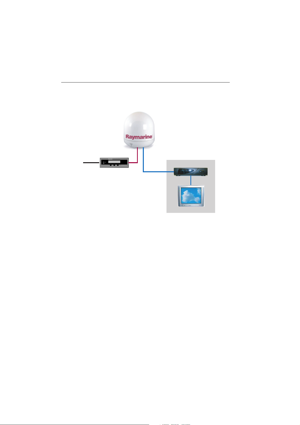
What does a typical system look like?
Raymarine 45 STV
Satelite TV Antenna
DC
Power
Note:
separately.
Satellite Receiver (IRD)
Antenna
Control Unit
Television
D7944_1
Satellite receivers, televisions and subscription services must be purchased
Page 9

Installation 7
Installation
EMC installation guidelines
All Raymarine equipment and accessories are designed to the best industry standards for use in
the recreational marine environment.
Their design and manufacture conforms to the appropriate Electromagnetic Compatibility
(EMC) standards, but correct installation is required to ensure that performance is not
compromised. Although every effort has been taken to ensure that they will perform under all
conditions, it is important to understand what factors could affect the operation of the product.
The guidelines given here describe the conditions for optimum EMC performance, but it is
recognized that it may not be possible to meet all of these conditions in all situations. To ensure
the best possible conditions for EMC performance within the constraints imposed by any
location, always ensure the maximum separation possible between different items of electrical
equipment.
For optimum EMC performance, it is recommended that wherever possible:
•Raymarine equipment and cables connected to it are:
• At least 3 ft. (1m) from any othe r equipment transmitting or carrying radio sig nals.
In the case of Single Side Band (SSB) radio, the distance should be increased to 7
ft. (2m).
• More than 7 ft. (2m) from the path of a radar beam. A rada r beam can normally be
assumed to spread 20 degrees above and below the radiating element.
•The equipment is supplied from a separate battery to that used for engine start.
Voltage drops below 10 V, and starter motor transients, can cause the
equipment to reset. This will not damage the equipment, but may cause the
loss of some information and may change the operating mode.
•Raymarine specified cables are used. Cutting and rejoining these cables can
compromise EMC performance and must be avoided unless doing so is detailed
in the installation manual.
Suppression Ferrite
If a suppression ferrite is attached to a cable, this ferrite should not be
removed. If the ferrite needs t o be removed during installation it must
be reassembled in the same position.
The illustration shows typical cable suppression ferrites used with
D7166_1
Raymarine equipment. Always use the ferrites supplied by Raymarin e.
Connections to other equipment
If your Raymarine equipment is to be connected to other equipment using a cable not
supplied by Raymarine, a suppressio n ferrite MUST always be attached to the cable near to
the Raymarine unit.
Page 10
8 Raymarine 45 STV Satellite Television System - Owner’s Handbook
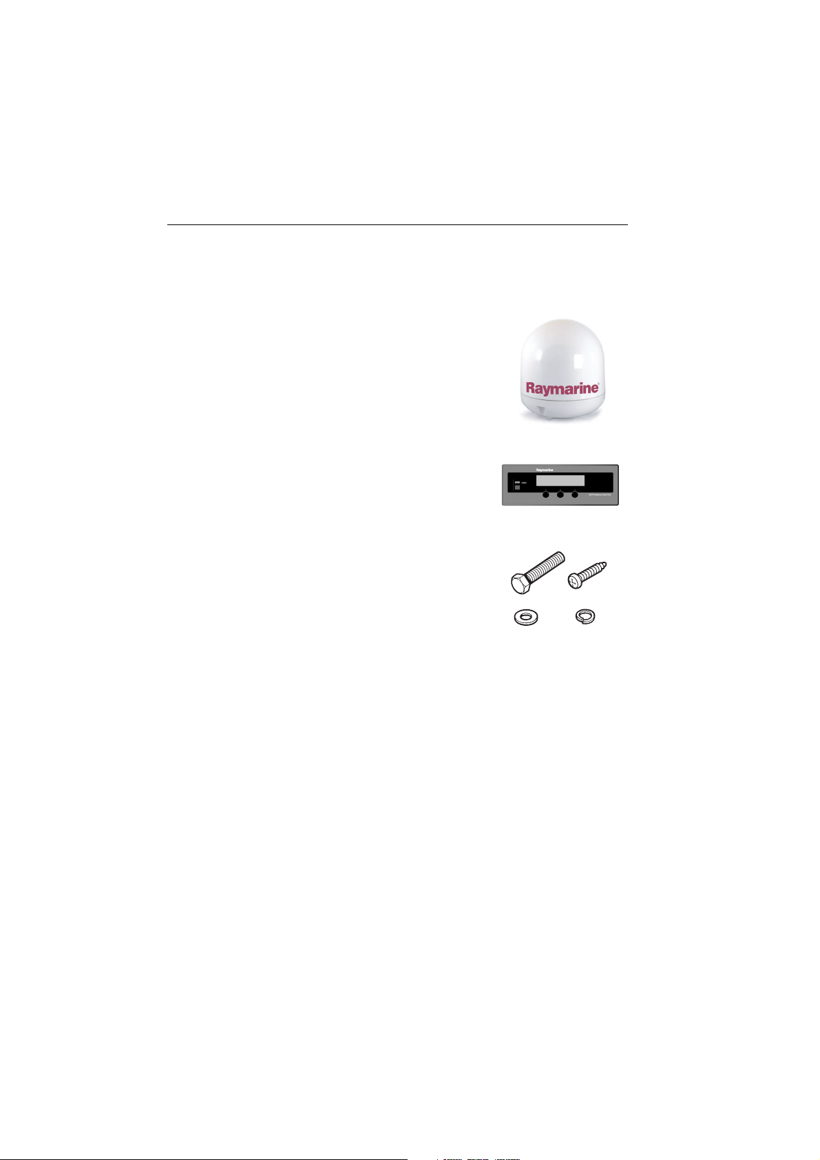
What’s in the box?....
Raymarine 45 STV Antenna Unit
houses the antenna positioning mechanism, low noise block
(LNB), power supply and c ontrol elements within a molded glass
fiber radome.
Connectors on the underside of the base plate join the power,
signal and control cabling from the below decks units.
D7945_1
Antenna Control Unit (ACU)
controls power to the antenna unit via the On/Off switch. The
three soft keys enable satellite programming and antenna
diagnostics to be carried out.
Installation kit
D7946_1
contains the items required for securing the antenna unit and
ACU to your boat.
• 4 x Hexagonal bolts.
•4 x Spring washers.
• 4 x Flat washers.
D7947_1
• 4 x Self tapping screws.
System cables
Your Raymarine 45 STV package also includes the following cables:
• RO8134 - 15 m Power and Data cable - used for connecting the antenna and ACU.
• RO8133 - 10 m Power cable - used for connecting the ACU to the DC power supply.
• RO 8135 - 15 m RF cable - used for connecting the Antenna and Integrated Receiver
Decoder (IRD).
• RO8138 - 1.8 m PC cable - used for connecting the ACU to a personal computer for
system set up and diagnostics.
CD-ROM
Contains the software for programming your system and carrying out system diagnostics
using a personal computer.
Page 11

Installation 9
What tools do I need to install my TV system?....
Power drill
80 mm (3 in)
hole saw
13 mm (1/2in)
spanner
Socket wrench
5 mm
Allen key
Pencil
Suitable waterproof
sealant
13 mm (1/2 in)
socket
Cross-head
screwdriver
10 mm (3/8 in)
drill
Adhesive tape
D7948_1
Page 12
10 Raymarine 45 STV Satellite Television System - Owner’s Handbook
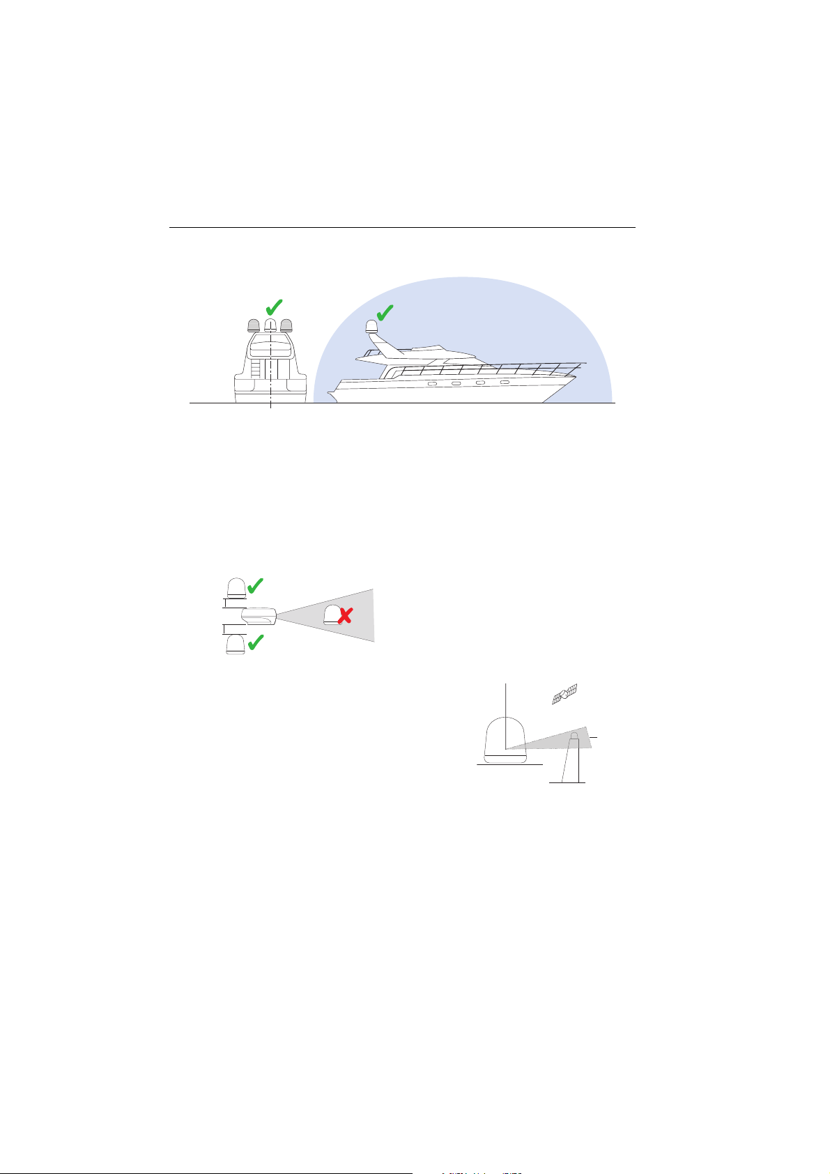
How do I plan the installation?....
Clear view of sky
D7949_1
When choosing a location for the antenna, consider the following points:
• Make sure you place it where there is an all round clear view of the horizon.
• It should not be too high above the water - the maximum recommended height
is one not exceeding half the length of your boat.
• It should be as near to the centerline of the boat as possible.
• The mounting platform should be rigid and not subject to excessive vibration.
• It should be away from the edge of the boat - this will avoid unnecessary motion
Min 1.2 m (4 ft)
Min 1.2 m (4 ft)
which can affect reception.
Above the beam
Below the beam
It should be clear of any radar as this may prevent
In the
the antenna working correctly.
beam
D7950_1
Make sure nearby objects do not block the
antenna. It requires a +15
0
to +900 look angle
0
90
to receive satellite signals
Cables
D7951_1
Mast
You need to consider the following points
before installing the system cables:
• All cables need to be adequately clamped and protected from physical damage
and exposure to heat - avoid running cables through bilges, doorways, or close
to moving objects.
• Acute bends must be avoided.
• Where a cable passes through an exposed bulkhead or deckhead, a watertight
gland or swan neck tube should be used.
+15
0
Blocked!
Page 13

Installation 11
Power requirements
You need to consider the following power requirements:
• Your Raymarine 45 STV Satellite TV system has been designed to work on a
boat’s power supply rated at 12 V DC.
• If your boats power supply is rated at 24 V DC you will need to install a suitable
DC power inverter to reduce the supply voltage to 12 V DC.
• If your IRD(s) and television(s) require a 220/240 V AC power supply, you will
need to install a suitable DC to AC converter to operate the units from your
boat’s DC power supply.
Extending the cables
The cables that have been supplied with your satellite TV system should be of
adequate length to complete the installation on most boats. However, should it
be necessary to extend a cable the following points should be considered:
Power and data cable
This cable is supplied at a length of 15 m.
If a longer length is required you should replace this cable with Part No. E96007
which will extend the available cable length to 30m.
Power cable
This cable is supplied at a length of 10 m.
If a longer length is required you should replace this cable with Part No. E96006
which will extend the available cable length to 30 m.
RF cable
This cable is supplied at a length of 15 m.
If a longer length is required you should replace this cable with Part No. E96008
which will extend the available cable length to 30m. Additional length can be
achieved by joining the supplied RF cable and the extension together to give a
maximum available cable length of 45m.
Note:
The stated cable lengths should not be exceeded as this may result in reduced
performance of your system.
Page 14
12 Raymarine 45 STV Satellite Television System - Owner’s Handbook
How do I install the ACU?....
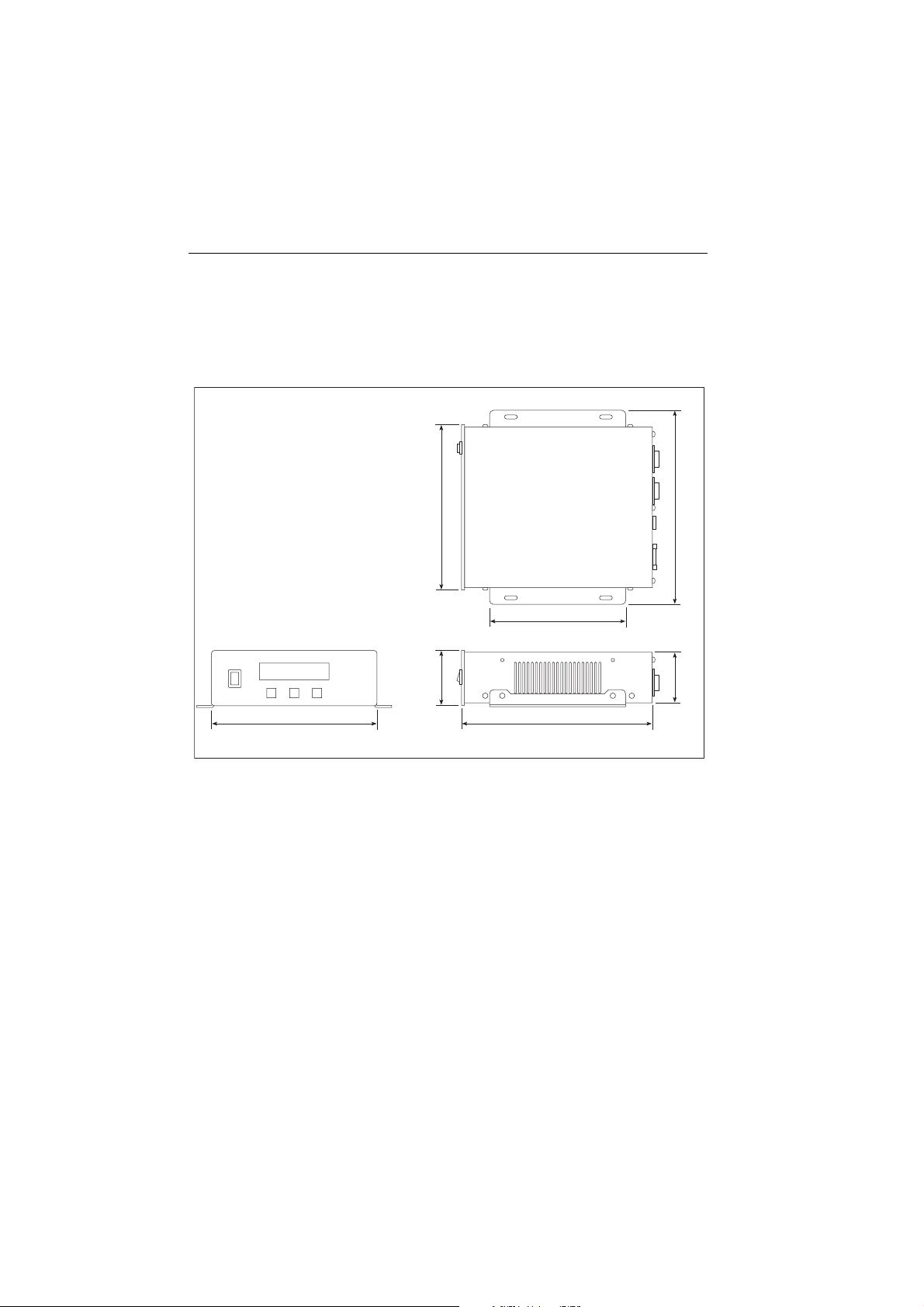
ACU dimensions
The dimensions of the ACU are shown below:
195 mm (7.67 in)
160 mm (6.3 in)
65 mm (2.56 in)
195 mm (7.67 in) 224.6 mm (8.84 in)
Installing the ACU
The ACU should be installed below decks, in a position that is:
•dry.
• well ventilated.
• easily accessible.
The ACU should be installed using the two fixing brackets supplied. These
brackets can be placed on the sides of the unit to provide a top or bottom fix.
229 mm (9.0 in)
62.7 mm (2.47 in)
D7952_1
Page 15
Installation 13
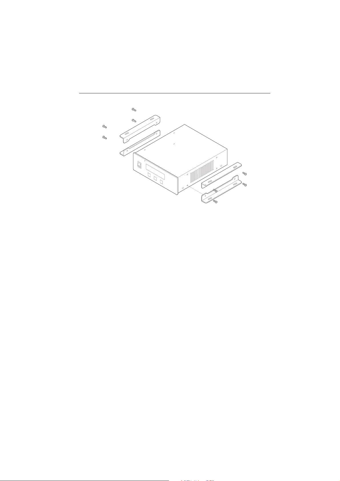
D7953_1
To install the ACU:
1. Select the installation site, ensuring that the proposed site meets the criteria
described above.
2. Using the screws supplied fix the mounting brackets to the sides of the ACU.
3. Place the ACU in the position where it is going to be installed.
4. Connect the cables to the rear of the ACU.
5. Using a pencil, mark the 4 hole positions (2 each side) for securing the
mounting brackets.
6. Using a suitable drill bit, drill the 4 holes in the required position.
It is good practice to countersink the mounting holes to avoid damage to the
mounting surface.
7. Using suitable screws, secure the ACU into position.
Page 16
14 Raymarine 45 STV Satellite Television System - Owner’s Handbook
How do I install the antenna?....
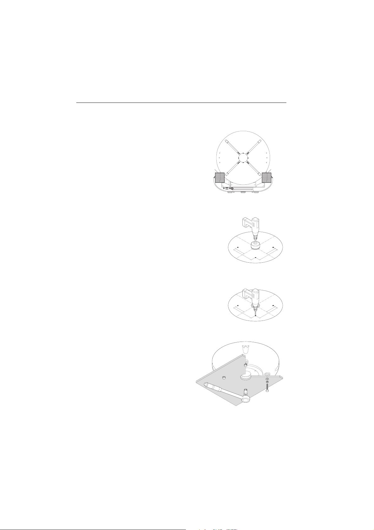
Preparing the antenna
1. Using a 5 mm allen key, remove the
antenna dome retaining bolts and
dome.
2. Remove the foam transit restraints
from the antenna base.
3. Replace and secure the antenna
dome .
Preparing the mount
1. Using adhesive tape, attach the template to the
mounting surface, ensuring that it is parallel to
your boat’s centerline as marked on the
template.
2. Using an 80 mm hole saw, remove the shaded
center portion
3. Drill four 10 mm holes in the positions indicated.
It is good practice to countersink the mounting
holes, and smooth the edges of the center hole
with a suitable file to avoid damage to the
mounting surface.
Foam
restraint
D
rill
10
h
m
d
ol
ia
e
m
4
m
,
C
p
(
e
4
u
os
ter
/
t
8
10
ho
0
it
i
inc
m
io
d
n
l
ia
e,
ns
m
h
m
)
(3
et
3
e
/
r
2
0
i
nc
h
es)
1
1
4.
3
m
m
(
4
1
/
2
i
n
c
he
s)
22
8
.6
m
m
(9
i
nc
h
es)
D
ri
ll h
10
d
ole
m
i
am
m
4
,
C
(
p
ete
4
ut
o
/
8
10
s
h
r
0
itio
i
ol
in
di
m
n
e
n
am
ch
m
,
s
)
(
e
3
t
3
er
/
2
0
in
ch
e
s)
11
4
.3
m
m
(4
1
/
2
i
nc
he
s)
22
8.
6
m
m
(9
in
ch
es
)
D7954_1
restraint
A
ntenn
1
(4
m
m
.3
14
1
)
inches
(9
m
.6 m
228
A
n
1
4
(
m
m
.3
4
1
1
)
s
inche
(9
m
m
.6
8
22
D7955_1
Foam
Te
a Ba
mp
se Un
lat
e
it
s)
inche
2
/
te
nna Ba
T
em
plat
se U
e
nit
es)
ch
in
2
/
Securing the antenna
Secure the antenna to the base using
bolts, spring washers and flat washers.
The bolts should be tightened to a
torque of 30 Nm (22.1 ft.lb.) to ensure
that the foam sealing ring is
compressed to prevent water ingress.
D7956_1
Page 17
Installation 15
How do I connect the system cables?....
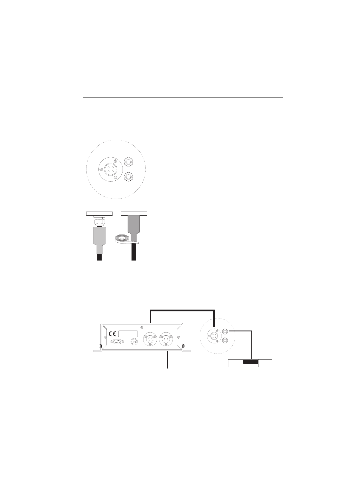
Connecting the antenna
1.Pass the power/data cable through the access hole of the
RF1
mounting plate and connect it to the power/data connector
on the antenna base plate.
Note:
It is good practice to coat the threads of all connector s
with a small amount of a suitable waterproof marine sealant prior
to securing them.
POWER
RF2
2.Secure the connector using a 13 mm spanner. Take care
not to over-tighten the nut, as this will damage the
connector.
3.Slide the cable shroud of the power/data cable over the
connection and fix in place using a suitable malleable
waterproof tape.
4.Remove the protective cap from the RF 1 connector.
5.Connect the RF cable to the RF 1 connector and secure
D7958_1
using a 13 mm spanner.Take care not to over-tighten the
nut, as this will damage the connector.
Note:
The baseplate connectors must be suitably protected from water ingress when the
antenna unit is installed on an open structure, e.g. a tuna tower.
Connecting the ACU
Power and data
PC INTERFACE FUSE ANTENNA DC10.8 - 15.6V
Boat's
DC power supply
POWER
RF1
RF2
IRD
(not supplied)
D7959_1
Page 18
16 Raymarine 45 STV Satellite Television System - Owner’s Handbook
CAUTION: In-line fuse
If you do not have a breaker in the power circuit, an in-line 5 A
quick blow fuse should be fitted to the positive (white) lead of the
power cable.
To connect the antenna control unit:
1. Connect the power and data cable to the connector on the rear panel of the
ACU.
2. Connect the RF cable to the connector on the rear panel of the IRD.
3. Connect the DC power supply to the connector on the rear of the ACU.
How do I configure the system?...
Your Raymarine 45 STV Satellite TV system can be connected with up to four IRDs
at the same time to receive pictures in different cabins offering the maximum
choice of channels. The following section shows the different combinations
available and their connections. In all cases the ACU must be connected to the
power/data connector of the antenna base plate.
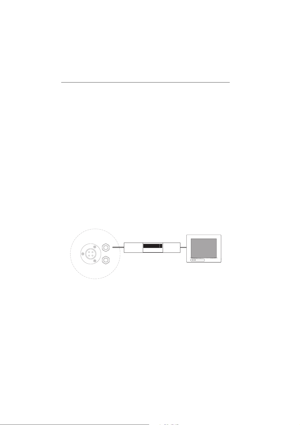
Single IRD
This is the basic method for connecting your Raymarine 45 STV system.
RF1
D7960_1
IRD
POWER
Antenna baseplate
RF2
(not supplied)
Television Monitor
(not supplied)
The RF cable from the antenna base plate should be connected to ‘LNB’, ‘ANT’ or
‘Satellite In’ on the rear panel of the IRD.
Page 19
Installation 17
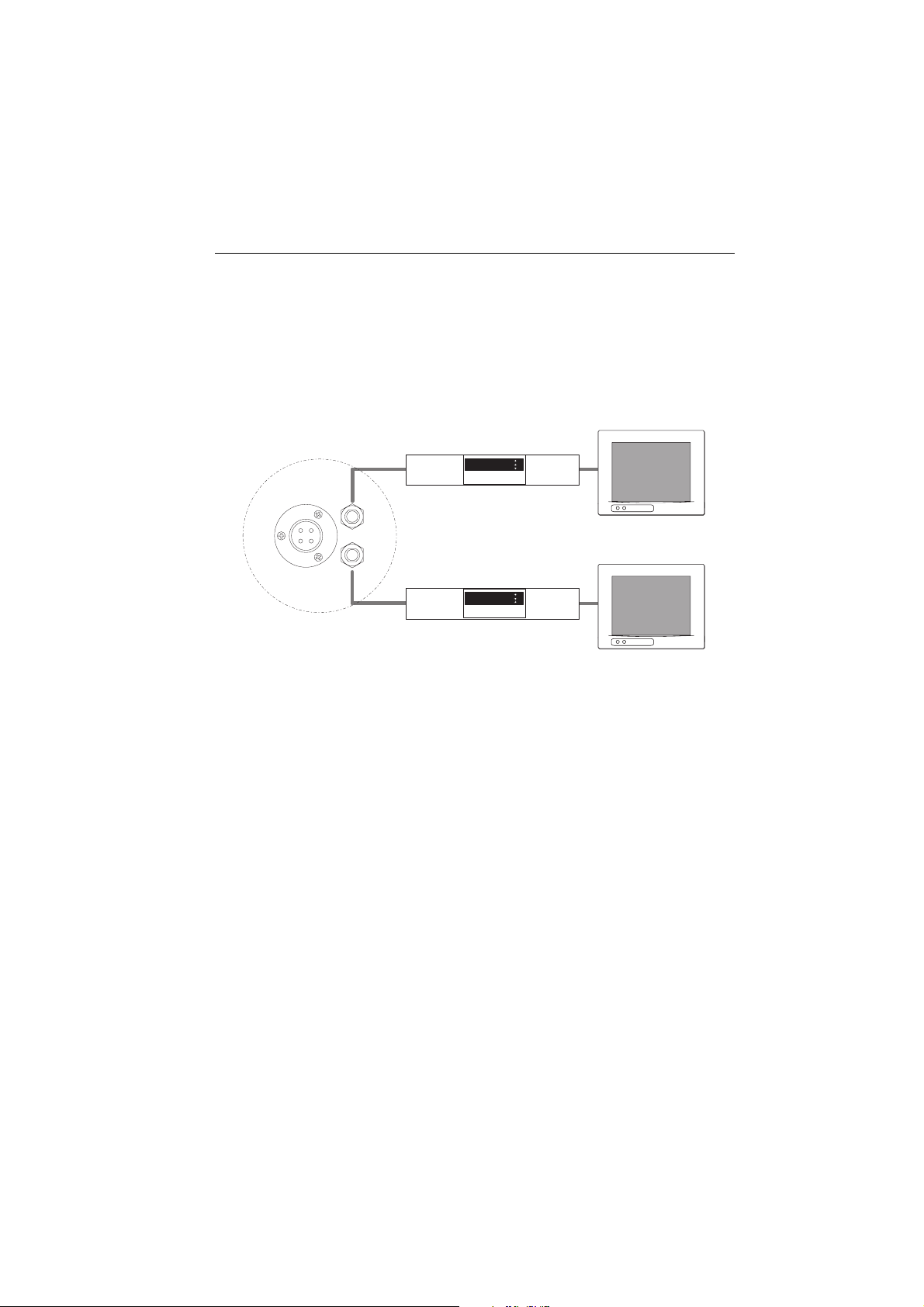
Twin IRDs
You can connect two IRDs to your antenna as shown in the following
diagram.However, only one of the IRDs can be configured as a two satellite
receiver. The other IRD needs to be configured as a one satellite receiver.
The two satellite receiver determines which satellite is tracked, while the other
receiver can watch any channel which is available from the tracked satellite.
POWER
Antenna baseplate
RF1
RF2
IRD 1
Television Monitor 1
D7961_1
IRD 2
Television Monitor 2
As in the single IRD option the RF cables from the antenna base plate should be
connected to ‘LNB’, ‘ANT’, or ‘Satellite In’ on the rear panel of the IRD.
Full details on configuring your system IRDs will be found in the relevant
Manufacturer’s handbook.
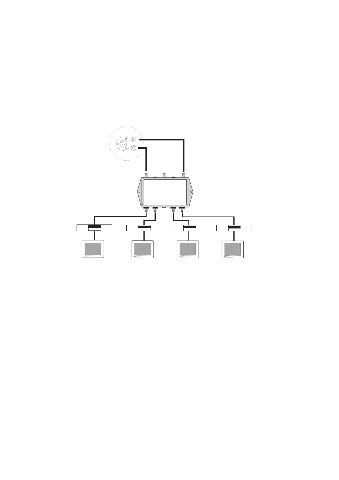
Three or four IRDs
IMPORTANT: Due to satellite polarization, incorrect conne ction in systems using
three or four IRDs will result in signal degradation. Make sure you select correct
method of connection for your area of operation.
North American systems
In order to connect three or four IRDs to the antenna, you will need to purchase an
active multi-switch (Raymarine recommends the Channel Master 6314 IFD), and
the necessary additional RF cables.
The multi-switch has to be installed between the antenna unit and the IRDs as
shown in the following diagram.
As in the two IRD system only one of the IRDs can be configured as a two satellite
receiver. The other IRDs need to be configured as one satellite receivers. The two
Page 20
18 Raymarine 45 STV Satellite Television System - Owner’s Handbook
satellite receiver determines which satellite is tracked, while the other receivers
can watch any channel which is available from that satellite.
RF1
RF2
Antenna
baseplate
POWER
LNB
RHCP/+13V
VHF/UHF
INPUT
POWER
24V DC
LNB
LHCP/ +18V
Multiswitch
GROUND
IRD 1
OUT 1 OUT 2
IRD 2
OUT 3 OUT 4
IRD 3 IRD 4
D7962_1
To connect three or four IRDs:
1. Connect an RF cable to RF1 and another to RF2 on the antenna base plate.
2. Connect the RF1 cable to LNB LHCP/+18 V on the multi-switch.
3. Connect the RF2 cable to LNB RHCP/+13 V on the multi-switch.
4. For each output required, connect an RF cable from an OUT connector of the
multi-switch to the LNB or ANT connector of the individual IRD units.
5. Terminate any unused connections with a suitable 75 Ohm DC terminator
block.
6. Connect the multi-switch to a 24 V DC power supply.
Page 21
Installation 19
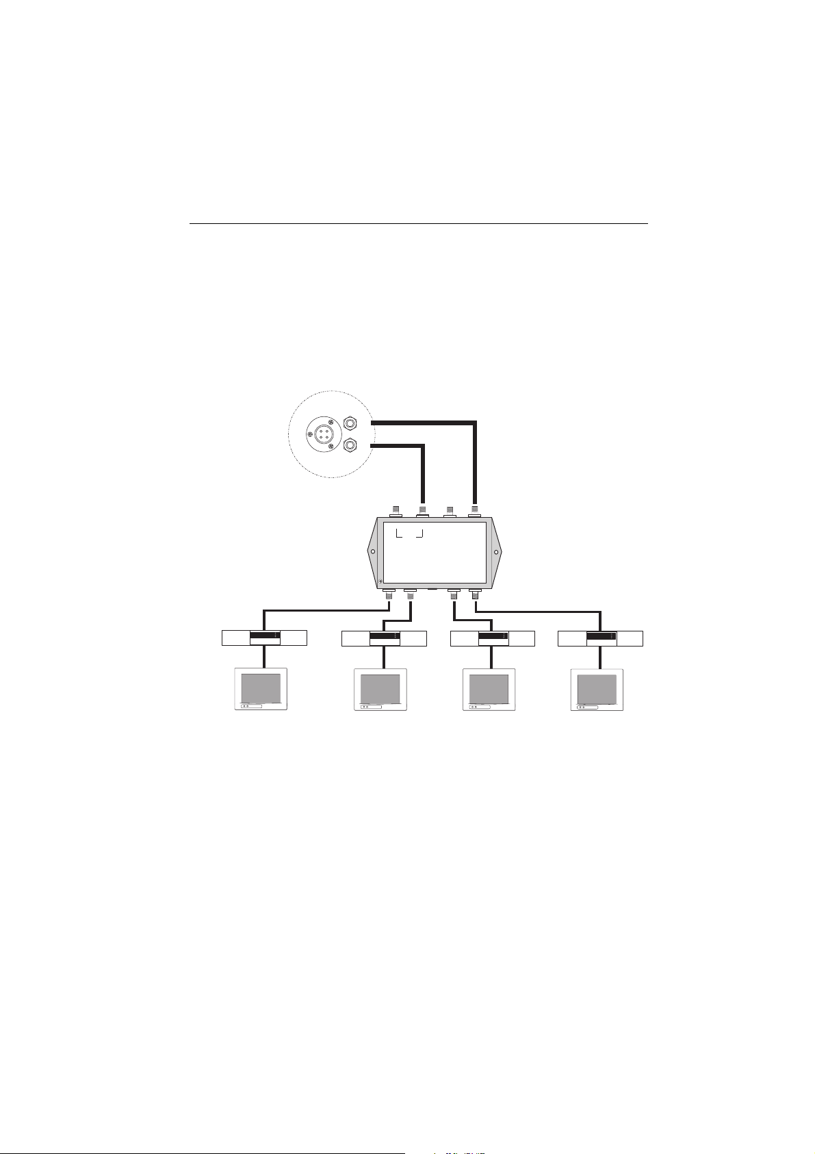
European systems
In order to connect three or four IRDs to the antenna, you will need to purchase a
suitable universal LNB multiswitch. The multiswitch has to be installed between
the antenna unit and the IRDs as shown in the following diagram.
You should connect to either the vertical or horizontal high and low pairs
depending whether you want to watch channels that are vertically or horizontally
polarized. Only those channels in the selected band will be available for viewing.
RF1
Antenna
baseplate
POWER/DATA
RF2
Hi/Hor Hi/Ver Lo/Hor Lo/Ver
OUT 1 OUT 2
DiSEqC
Multiswitch
POWER
24V DC
OUT 3 OUT 4
IRD 1
IRD 2
IRD 3
IRD 4
D7963_1
To connect three or four IRDs:
1. Connect an RF cable to RF1 and another to RF2 on the antenna base plate.
2. Connect the RF1 cable to Lo/Ver Lo/Hor on the multiswitch depending
whether the desired programming is in the vertical or horizintal low band.
3. Connect the RF2 cable to Hi/Ver or Hi/Hor on the multiswitch depending
whether the desired programming is in the vertical or horizintal low band.
4. For each output required, connect an RF cable from an OUT connector of the
signal splitter to the LNB or ANT connector of the individual IRD units.
5. Terminate any unused connections with a suitable 75 Ohm DC terminator
block.
Page 22

20 Raymarine 45 STV Satellite Television System - Owner’s Handbook
Page 23

System set up 21
System set up
Introduction
This section of the handbook describes how to set up your Raymarine 45 STV
Satellite TV system after installation using the ACU or the Graphical User Interface
(GUI) and includes the following functions:
• System start up.
• Change the default satellite.
• Monitor the antenna status.
• Enter set up mode.
• Setting the satellite pair.
• Setting the GPS.
• Setting the local frequency.
• Setting the DiSEqC method.
•Display versions.
• Setting antenna go position.
• Setting antenna move step.
• Setting the default satellites.
Many of the above functions will only be required at initial installation of your
system.
Note:
The satellite names shown on the ACU screen in the following illustrations may
differ from those on your ACU depending on your geographic location.
Page 24

22 Raymarine 45 STV Satellite TV System - Owner’s Handbook
Set up using the ACU
Start up
With the system installed and power applied, the ACU screen will show the
following sequence:
INITIALIZE ACU
RAYMARINE 45STV
D7964_1
INITIALIZE ANTENNA
RAYMARINE 45STV
D7965_1
SEARCHING A: ASTRA2
B: HOTBIRD SETUP
D7966_1
TRACKING A: ASTRA2
B: HOTBIRD SETUP
D7967_1
Changing the default satellite
1. Communication is being
established between the
antenna and the ACU
2. The antenna is initialized.
3. The antenna is searching for
Satellite A.
4. The antenna has located the
satellite and is now tracking it.
TRACKING A: ASTRA2
B: HOTBIRD SETUP
TRACKING B: HOTBIRD
A: ASTRA 2 SETUP
D7968_1
Your ACU is programmed with two default satellites. To change the default
satellite, press the left hand soft key. The default satellite changes and is
automatically tracked by the antenna.
Page 25

System set up 23
Monitoring the current status of the antenna
SEARCHING A: ASTRA2
B: HOTBIRD SETUP
TRACKING A: ASTRA2
B: HOTBIRD SETUP
ANTENNA IS UNWRAPPING
B: HOTBIRD SETUP
TRACKING A: ASTRA2
B: HOTBIRD SETUP
1. Antenna is searching for satellite A.
D7966_1
2. Antenna is tracking satellite A.
D7967_1
3. Antenna is unwrapping the wire.
D7969_1
4. Antenna is again tracking satellite A.
D7970_1
Press to display position detail.
AZ:###.# EL:###.#
SIGNAL:### SETUP
5. Antenna position detail and signal
D7971_1
strength is displayed.
Press SET UP to return to main set up
menu.
Page 26

24 Raymarine 45 STV Satellite TV System - Owner’s Handbook
Set up mode
To enter set up mode:
TRACKING A: ASTRA 2
B : HOTBIRD SETUP
1. With the antenna tracking press
D7972_1
SETUP.
SETUP MODE?
YES NO
SET SAT PAIR?
PREV YES NEXT
2. Press YES to enter setup mode.
D7973_1
3. Press YES to set the satellite pair.
D7974_1
Page 27

System set up 25
Setting the satellite pair
This sequence applies to all satellite pairs except DirecTV:
SET SAT PAIR?
PREV YES NEXT
SAT A : ASTRA 2
NEXT SELECT EDIT
SAT B: HOTBIRD
NEXT SELECT EXIT
SAVE?
YES NO
1. Follow steps 1 thru 3 for entering set
up mode. Press YES to set satellite pair.
D7974_1
2. Set satellite A.
Press NEXT to show alternative
satellite name.
Press SELECT to set chosen satellite to
D7975_1
SAT A.
Press EXIT to return to main set up
menu.
3. Set satellite B.
Press NEXT to show alternative
satellite name.
Press SELECT to set chosen satellite to
D7976_1
SAT A.
Press EXIT to return to main set up
menu.
4. Press YES to save selections.
Press NO to cancel and return to main
setup menu.
D7977_1
Page 28

26 Raymarine 45 STV Satellite TV System - Owner’s Handbook
Setting the satellite pair - DirecTV
SET SAT PAIR?
PREV YES NEXT
SAT A : DTV101
NEXT SELECT EDIT
SAT B: DTV101
NEXT SELECT EXIT
SAT A* : DTV119
NEXT SELECT EXIT
1. Follow steps 1 thru 3 for entering set up
mode. Press YES to set satellite pair.
D7974_1
2. Set satellite A.
Press NEXT to show alternative
satellite name.
Press SELECT to set chosen satellite to
D78642_1
SAT A.
Press EXIT to return to main set up
menu.
3. Set satellite B.
Press NEXT to show alternative
satellite name.
Press SELECT to set chosen satellite to
D8643_1
SAT A.
Press EXIT to return to main set up
menu.
4. Set satellite A when DiSEqC is active
from IRD.
Press NEXT to show alternative
satellite name.
D8644_1
Press SELECT to set chosen satellite to
SAT A.
Press EXIT to return to main set up
menu.
Page 29

System set up 27
SAT B* : DTV110
SAVE?
Note:
NEXT SELECT EXIT
YES NO
DiSEqC is not used with Dish Network or ExpressVu satellites.
Setting the GPS
SETUP MODE?
YES NO
5. Set satellite B when DiSEqC is active
from IRD.
Press NEXT to show alternative
satellite name.
D8645_1
Press SELECT to set chosen satellite to
SAT A.
Press EXIT to return to main set up
menu.
6. Press YES to save selections.
Press NO to cancel and return to main
setup menu.
D7977_1
1. Press YES to enter set up mode.
D7973_1
SET SAT PAIR?
PREV YES NEXT
2. Press NEXT to enter GPS set up
D7974_1
mode.
Page 30

28 Raymarine 45 STV Satellite TV System - Owner’s Handbook
SET GPS?
LONGITUDE 28.20E
LATITUDE ##.##N
PREV YES NEXT
_
+ INPUT -
+ INPUT -
-
3. Press YES to set GPS.
D7980_1
4. Input the longitude data.
+ increases a value. - decreases a
D7981_1
value.
Change the underscored digit using
the +/- buttons.
Press INPUT to accept a value.
5. Input the latitude data.
+ increases a value. - decreases a
D7982_1
value.
Change the underscored digit using
the +/- buttons.
Press INPUT to accept a value
SAVE?
YES NO
6. Press YES to accept the data.
Press NO to cancel and return to
D7977_1
main set up menu.
Page 31

System set up 29
Edit satellite information
SETUP MODE?
YES NO
SET SAT PAIR?
PREV YES NEXT
EDIT SAT INFO?
PREV YES NEXT
SATNAME : ASTRA 2
NEXT SELECT EXIT
1. Press YES to enter set up mode.
D7973_1
2. Press NEXT twice to enter Edit Sat
D7974_1
Info menu.
3. Press YES to enter edit menu.
D7983_1
4. Set the satellite name.
NEXT - shows next satellite name.
D7984_1
SELECT - sets the displayed satellite
for editing.
EXIT - returns to the main set up
menu.
SATNAME : ASTRA 2
+ INPUT -
5. Input satellite name.
+ increases a value. - decreases a
D7985_1
value.
Change the underscored digit using
the +/- buttons.
Press INPUT to accept a value
Page 32

30 Raymarine 45 STV Satellite TV System - Owner’s Handbook
LONGITUDE 28.20E
VER LOW 10788 22000
VER LOW NID 0X0020
HOR LOW 10773 22000
_
+ INPUT -
+ INPUT -
+ INPUT -
+ INPUT -
6. Input satellite position
D7981_1
7. Input the tracking frequency (MHz)
D7986_1
and symbol rate (kHz) for Vertical
Low Band.
8. Input the Network ID (NID) for
D7987_1
Vertical Low B and.
9. Input the tracking frequency (MHz)
D7988_1
and symbol rate (kHz) for Horizontal
Low Band.
HOR LOW NID 0X0020
+ INPUT -
VER HIGH 11895 27500
+ INPUT -
10. Input the NID for Horizontal Low
D7989_1
Band.
11. Input the tracking frequency (MHz)
D7990_1
and symbol rate (kHz) for Vertical
High Band.
Page 33

System set up 31
VER HIGH NID 0X0020
HOR HIGH 11954 27500
HOR HIGH NID 0X0020
VERIFY : DVB DECODE
+ INPUT -
+ INPUT -
+ INPUT -
PREV SELECT NEXT
12. Input the NID for Vertical High Band.
D7991_1
13. Input the tracking frequency (MHz)
D7992_1
and symbol rate (kHz) for Horizontal
High Band.
14. Input the NID for Horizontal High
D7993_1
Band.
15. Select the verification method * of
tracking satellite.
D7994_1
PREV - shows previous method.
SELECT - set the displayed method.
NEXT - shows next method.
Page 34

32 Raymarine 45 STV Satellite TV System - Owner’s Handbook
POWER : AUTO
PREV SELECT NEXT
16. Select the power supplying method
** to the LNB. AUTO is
D7995_1
recommended.
PREV - shows previous method.
SELECT - set the displayed method.
NEXT - shows next method.
SAVE?
YES NO
* Verification methods ** Power supplying methods
SIGNAL - use only signal level for tracking.
DVB LOCK - use only DVB lock signal for
tracking.
DVB DECODE - verify satellite using DVB
decoding method for tracking.
DSS LOCK - use only DSS lock signal for
tracking.
17. Press YES to accept the data.
Press NO to cancel and return to
D7977_1
main set up mode.
AUTO - change voltage to LNB by IRD
voltage.
ON LY 13 V - alwa ys s upp ly 13 V to L NB.
ON LY 18 V - alwa ys s upp ly 18 V to L NB.
Notes: (1)
(2)
Raymarine does not recommend changing the satellite information unless
advised to do so by the satellite provider.
Vetical and horizontal polarization applies to European satellites only.
Page 35

System set up 33
Setting the local frequency
US LNB systems
SETUP MODE?
YES NO
SET SAT PAIR?
PREV YES NEXT
SET LOCAL FRQ?
PREV YES NEXT
LNB TYPE : SINGLE
PREV SELECT NEXT
1. Press YES to enter set up mode.
D7973_1
2. Press NEXT 3 times to enter the
D8646_1
Local frequency menu.
3. Press YES to set local frequency.
D7996_1
4. Select SINGLE LNB type.
PREV - shows previous LNB type.
SELECT - sets the displayed LNB
D7997_1
type.
NEXT - shows the next LNB type.
Page 36

34 Raymarine 45 STV Satellite TV System - Owner’s Handbook
LOCAL FREQ : ####MHZ
SAVE?
+ INPUT -
YES NO
EU LNB systems
SETUP MODE?
YES NO
5. Input local frequency for the LNB.
+ increases a value. - decreases a
value.
D7998_1
Change the underscored digit
using the +/- buttons.
Press INPUT to accept a value
6. Press YES to accept the data.
Press NO to cancel and return to
D7977_1
main set up menu.
1. Press YES to enter set up mode.
D7973_1
SET SAT PAIR?
PREV YES NEXT
SET LOCAL FRQ?
PREV YES NEXT
2. Press NEXT 3 times to enter Local
D8646_1
frequency menu.
3. Press YES to set local frequency.
D7996_1
Page 37

System set up 35
LNB TYPE : UNIVERSAL
SAVE?
PREV SELECT NEXT
D7999_1
YES NO
D7977_1
Setting the DiSEqC method
SETUP MODE?
YES NO
D7973_1
4. Select UNIVERSAL LNB type.
PREV - shows previous LNB type.
SELECT - sets the displayed LNB
type.
NEXT - shows the next LNB type.
5. Press YES to accept the data.
Press NO to cancel and return to
main set up menu.
1. Press YES to enter set up mode.
SET SAT PAIR?
PREV YES NEXT
USE DISEQC?
PREV YES NEXT
2. Press NEXT 4 times to go to the Use
DiSEqC menu.
D8646_1
3. Press YES to enter the DiSEqC menu.
D8000_1
Page 38

36 Raymarine 45 STV Satellite TV System - Owner’s Handbook
DO NOT USE DISEQC
PREV SELECT NEXT
4. Select the DiSEqC method*
NEXT - shows next DiSEqC method.
SELECT - sets the displayed method.
D8001_1
EXIT - returns to main set up menu.
SAVE?
YES NO
5. Press YES to accept the selection.
Press NO to cancel and return to main
D7977_1
set up menu.
* DiSEqC method
DO NOT USE DISEQC - DiSEqC is not used.
USE TO CHANGE BAND - DiSEqC is used to change high and low bands (Europe).
USE TO CHANGE SAT - DiSEqC is used to change satellite being tracked (US - DirecTV).
Display version
This sequence enables you to see what version of antenna and ACU software
versions are installed on your system.
SETUP MODE?
YES NO
SET SAT PAIR?
PREV YES NEXT
1. Press YES to enter set up mode.
D7973_1
2. Press NEXT 5 times to go to View
Version menu.
D8646_1
Page 39

System set up 37
ACU S/W VER : 1.00
EXIT
D8002_1
VIEW VERSION?
PREV YES NEXT
D8002_1
ACU S/W VER : 1.00
EXIT
D8002_1
Setting antenna go position
3. Press YES to view software
versions.
4. Antenna software version
displayed.
Press center soft key to view ACU
software version.
5. ACU soft ware version is displayed.
Press EXIT to return to main set up
menu.
SETUP MODE?
YES NO
SET SAT PAIR?
PREV YES NEXT
1. Press YES to enter set up mode.
D7973_1
2. Press NEXT 6 times to enter Go
D8646_1
Position menu.
Page 40

38 Raymarine 45 STV Satellite TV System - Owner’s Handbook
ANTENNA GO POSITION?
PREV YES NEXT
AZ : ###.##DEG
+ INPUT -
EL : ###.##DEG
+ INPUT -
3. Press YES to enter Go position.
D8002_1
4. Input position value for azimuth
(AZ) axis.
+ increases a value. - decreases a
D8006_1
value.
Change the underscored digit
using the +/- buttons.
Press INPUT to accept a value.
5. Input position value for elevation
(EL) axis.
+ increases a value. - decreases a
D8007_1
value.
Change the underscored digit
using the +/- buttons.
Press INPUT to accept a value.
GO TO POSITION?
YES NO
AZ:###.## EL:###.#
EXIT
6. Press YES to send position
command and display current
D8008_1
position during motion.
Press NO to return to antenna go
position menu.
7. Press EXIT to return to main set up
D8009_1
menu.
Page 41

System set up 39
Setting antenna move step
SETUP MODE?
YES NO
SET SAT PAIR?
PREV YES NEXT
ANT MOVE STEP?
PREV YES NEXT
STEP AZ : ###.#
CW EL CCW
1. Press YES to enter set up mode.
D7973_1
2. Press NEXT 7 times to go to the Ant
D8646_1
move step menu.
3. Press YES to enter the Ant move
D8010_1
step menu.
4. Move the antenna in the AZ axis.
CW - move clockwise.
EL - go to the elevation control
D8011_1
screen.
CCW - move counter-clockwise.
STEP EL : ###.#
UP EXIT DOWN
5. Move the antenna in the EL axis.
UP - move in u p direc tion.
EXIT - go to Ant move step menu.
D8012_1
DOWN - move in down direction.
Page 42

40 Raymarine 45 STV Satellite TV System - Owner’s Handbook
Setting defaults
SETUP MODE?
YES NO
SET SAT PAIR?
PREV YES NEXT
SET DEFAULT?
PREV YES NEXT
1. Press YES to enter set up mode.
D7973_1
2. Press NEXT 9 times to go to Set
D8646_1
default menu.
3. Press YES to set default
D8013_1
parameters.
Page 43

System set up 41
Set up using the Graphical User Interface
You can also set up your Raymarine 45 STV system using the Graphical User
Interface (GUI) which can be found on the CD-ROM. The CD-ROM contains a
folder for both US and European satellite systems. Open the correct folder for your
area of operation. The method of operation is the same for both versions of the
GUI.
D8014_1
The GUI program enables you to set up the antenna through a PC to maximize
system performance and diagnostics.
To operate the GUI
1. Connect one end of the PC data cable to the PC INTERFACE connector on the
rear of the ACU.
2. Connect the other end of the PC data cable to a serial port or serial to USB
converter on your PC.
3. Place the CD-ROM supplied with your system into the CD-ROM drive of your
computer.
4. Using Windows Explorer to access the contents of the CD-ROM, open the
program ‘Raymarine 45 STV Controller.exe’. The GUI will be displayed on your
PC screen.
5. Power up the antenna and ACU.
Page 44

42 Raymarine 45 STV Satellite TV System - Owner’s Handbook
GUI main menu
Controller
menu
Target satellite selection
and monitoring
Satellite pair
(Target satellite shown in box)
Antenna
status
D8015_1
The GUI main menu allows you to select a function and to see the antenna status
at a glance, and consists of the following areas:
Local frequency
Signal strength
Controller menu
The controller menu enables you to select the task that you want to carry out.
Place the cursor over the required task, which will be highlighted in blue, click,
and the GUI will change to show the data boxes relevant to that task.
Antenna status
The antenna status information shows monitoring and set up information for your
antenna.
Target satellite selection and monitoring
This section enables you to set up satellite tracking and monitoring.
Satellite pair
This section shows satellites being tracked.
Local frequency and signal strength
This section shows the local satellite frequency and signal strength.
Page 45

System set up 43
Serial port set up
Having connected the ACU to your PC, communication must be established
between the two., this requires the communication speed and the serial port to be
set up. You can then use the GUI to configure the antenna settings.
To set up the serial port
1. Connect the ACU and PC as described in “To operate the GUI” on page 41.
2. From the menu options select ‘Serial Communication. The serial
communication screen is displayed.
3. Click on the drop down menu to select the baudrate setting. It should be
19200 bps.
4. Click the circle next to the serial port number that you want to use. The
selected port is shown next to the baudrate setting.
5. Click the ‘Connect/ Disconnect’ button to establish communication. The
button label changes as you click to show connection status.
Once communication between the ACU and antenna has been established you
can configure the settings for your antenna.
Baudrate setting
Connection status
Serial port setting
D8016_1
Page 46

44 Raymarine 45 STV Satellite TV System - Owner’s Handbook
The GUI control soft keys
The following is an explanation of the operation of the different GUI soft keys:
D8359_1
Restart
Click this soft key to restart the antenna tracking the chosen satellite.
Setup
Click this soft key to enter the GUI set up mode prior to making any changes.
Get Antenna Information
Click this soft key to display the current system settings.
Advanced Control
This is a password protected area for dealer use only.
View Data
Click this soft key to load the factory default settings into the GUI program.
Update Antenna
Click this soft key to send the factory default settings to the antenna. Remember
that this will not restart the system.
Page 47

System set up 45
Setting the GPS
Your system antenn a uses GP S information to enable it to track the satellite faster.
The better the GPS information, the better the antenna performance.
Position stored
in the antenna
D8017_1
There are two ways in which GPS information can be edited:
Method 1- Your actual position
By obtaining your exact position from your boat’s GPS system, you can input this
into the antenna memory.
1. Click ‘Set Antenna GPS and Find Antenna Angle’ in the menu options. The set
GPS screen is displayed..
2. Click ‘Setup’. The GUI will now enter set up mode.
3. Click on the Longitude box and enter your longitude in degrees and minutes
format, e.g. 71.50
o
.
4. Click the drop-down arrow at the right of the longitude box and select W or E
according to your longitude.
5. Click on the latitude box and enter your latitude in degrees and minutes
format.
6. Click the drop-down arrow at the right of the latitude box and select N or S
according to your latitude.
7. Click ‘Set GPS’ to save this information and set the GPS.
Page 48

46 Raymarine 45 STV Satellite TV System - Owner’s Handbook
8. Click ‘Restart’. The system leaves set up mode and the antenna will start
tracking.
Method 2 - Selecting the nearest city.
If your are unable to enter your exact position, you can enter the latitude and
longitude for the nearest city.
1. Click ‘Set Antenna GPS and Find Antenna Angle’ in the menu options. The set
GPS screen is displayed.
2. Click ‘Setup’. The GUI will now enter set up mode.
3. Click on the arrow at the right of the ‘City’ box. A drop-down menu of city
names according to your area of operation (US or Europe) appears.
4. Scroll down the list and select the city which is nearest to your current
position. The latitude and longitude information for the selected city is
displayed.
5. Click ‘Set GPS’ to save this information.
6. Click ‘Restart’. The system leaves set up mode and the antenna will start
tracking.
Page 49

System set up 47
Editing the satellite information
This section of the GUI enables you to edit satellite information
D8018_1
To edit a satellite’s information:
1. Click ‘Set Satellite Information’ in the menu options. The set satellite
information screen is displayed.
2. Click ‘Setup’. The GUI will now enter set up mode.
3. Click on the arrow at the right of the Satellite box. A drop-down menu of
satellites appears.
4. Scroll down and select the satellite that you want to edit. The satellite name,
its latitude and longitude and method of verification will be displayed.
You can now change and edit the data for the selected satellite using the
following command buttons:
• Register for Satellite A - registers the selected satellite as Sat A of the
satellite pair.
• Register for Satellite B - registers the selected satellite as Sat B of the
5. Click ‘Restart’. The system leaves set up mode and the antenna will start
tracking.
Page 50

48 Raymarine 45 STV Satellite TV System - Owner’s Handbook
Setting antenna angle, move step and diagnosis.
You can move the antenna to a new target position or carry out diagnosis using
the Move antenna - Execute diagnosis function of the GUI.
D8020_1
Moving the antenna to a new position
There are two methods for moving (stepping) the antenna to a new position:
• Positioning based on an absolute angle.
• Positioning based on a relative angle.
To position using an absolute angle:
1. Click ‘Move Antenna - Execute Diagnosis ‘in the menu options. The move
antenna screen appears.
2. Click ‘Setup’. The GUI will now enter set up mode.
3. Enter the azimuth (AZ) and elevation (EL) angle values in the corresponding
‘Target ‘boxes of the ‘Go to position’ box.
4. Click ‘Go to Target Position’. The antenna will move to the new target
position.
5. Click ‘Restart’. The system leaves set up mode and the antenna will start
tracking.
To position using a relative angle:
1. Click ‘Move Antenna - Execute Diagnosis ‘in the menu options. The move
antenna screen appears
2. Click ‘Setup’. The GUI will now enter set up mode.
3. Enter the angle that you want the antenna to move in the relevant boxes of
the ‘Move Step’ box.The box marked with up/down arrows will adjust the EL
position, the box marked with left/right arrows adjusts the AZ position.
Page 51

System set up 49
4. Click the arrow corresponding to the direction that you want the antenna to
5. Click ‘Restart’. The system leaves set up mode and the antenna will start
tracking.
Antenna diagnosis
The antenna diagnosis function, automatically tests the operation of the system
and shows it status.
To carry out antenna diagnosis:
1. Click ‘Move Antenna - Execute Diagnosis ‘in the menu options. The move
antenna screen appears.
2. Click ‘Setup’. The GUI will now enter set up mode.
3. Click the ‘Diagnosis’ button. Antenna diagnosis is automatically carried out.
As each function is tested the result is shown by the circle next to the function
title in the diagnosis box changing color.
• Blue - shows the function is operating correctly.
• Green - shows the function is being tested.
• Red - shows that there is a fault with that function.
If a fault is diagnosed refer to “Troubleshooting” on page 51 for possible
solutions.
4. Click ‘Restart’. The system leaves set up mode and the antenna will start
tracking.
Page 52

50 Raymarine 45 STV Satellite TV System - Owner’s Handbook
Setting the skew angle
Note:
This section is only applicable to EU systems.
If you move to a different geographic location, you may need to adjust the skew
angle of the LNB to maximize satellite signal reception. For details of the correct
skew angle refer to the local satellite television provider.
The skew angle of the LNB is shown by a circular skew angle guide attached to the
LNB.
D8021_1
To adjust the LNB skew angle:
1. Ensure the system is powered OFF.
2. Remove the antenna unit cover.
3. Loosen the four screws securing the LNB in the choke feed.
LNB
Antenna
flange
D8022_1
4. Carefully turn the LNB to match the required skew angle as close as possible.
5. Tighten the LNB securing screws.
6. Refit the antenna unit cover.
7. Power the system ON and function test.
Page 53

Maintenance and troubleshooting 51
Maintenance and troubleshooting
Introduction
This section deals with maintenance and troubleshooting that can be carried out
by the system user.
Maintenance
WARNING: Power supply
Ensure that the system is isolated from your boat’s power supply
before carrying out any maintenance.
Your Raymarine 45 STV Satellite TV system has been designed to require minimal
maintenance. The following routine maintenance checks will ensure that your
system maintains peak performance:
• Examine the cables for signs of damage, such as chafing, cuts or nicks.
• Check that all cables are firmly attached.
• Wash the exterior of the antenna cover with fresh water to remove salt
deposits; a mild detergent may be added to remove grime. DO NOT use
abrasive cleaners or solvents such as acetone as this may result in irreparable
damage to the unit.
• The antenna is not a sealed unit, DO NOT use a power spray to wash the
exterior as this may result in water ingress and damage to the unit.
• Twice a year remove the antenna cover and examine the interior for signs of
corrosion.
Troubleshooting
Your Raymarine product has been subjected to comprehensive test and quality
assurance programs prior to packing and shipping. However, if your unit should
develop a fault, please refer to the following table to identify the most likely cause
and the corrective action required to restore normal operation.
If you still have a problem after referring to the table, contact your local
Raymarine dealer, national distributor or Raymarine Product Support for further
advice.
Page 54

52 Raymarine 45 STV Satellite TV System - Owner’s Handbook
Symptom
Antenna not functioning X
No picture on TV set XXXX
Intermittent picture for short intervals XXXXX X
System works at the dock but not underway X
System will not find satellite XXXXXXX
‘Snowy’ television picture X
Note:
* for an explanation of possible causes and their remedies refer to the following
Possible cause*
12345678
paragraphs.
1. Blown fuse, low power or wiring
• Check that the in-line quick blow fuse (if fitted) has not blown, or the circuit
breaker has not tripped. Replace fuse with one of the same type and rating.
• If you have extended the power cable from the antenna unit, check that there
is no power loss.
• Check the system wiring and connections.
2. Satellite signal blocked
Satellite signals can be blocked or degraded by buildings, other boats, or
equipment on your boat. Check that the antenna has a clear view of the sky.
3. Outside satellite coverage zone
Your system will provide excellent reception within the antenna coverage area for
your satellite television service. However, signal quality may degrade as you
approach the edges of this zone. Refer to “Satellite information” on page 57 to
check the viable coverage area for your antenna.
4. Radar interference
The energy levels radiated by radar units can overload the antenna front-end
circuits. Make sure that your antenna is installed as described in “How do I plan
the installation?....” on page 10 of this handbook with regards to your radar unit.
Page 55

Maintenance and troubleshooting 53
5. Incorrect or loose RF connectors
As part of the regular maintenance recommended by Raymarine, all connections
should be checked to ensure that they have not become loose. A loose RF
connector can reduce signal quality.
5. Multi-switch interference
If you have multiple IRD’s connected to your system, make sure that you are using
an ACTIVE not PASSIVE multi-switch.
7. IRD troubleshooting
Your IRD may be the cause of less than ideal operation.
1. Check the IRDs configuration to ensure that it is programmed for the area in
which you are operating.
2. Unplug the IRD from the power supply for 15 seconds. Reconnect and allow
the system to intialize.
8. LNB fault
If you have an LNB fault, it may require replacing. Contact your local dealer,
national distributor or Raymarine Product Support for further assistance.
Page 56

54 Raymarine 45 STV Satellite TV System - Owner’s Handbook
Antenna diagnosis
SETUP MODE?
YES NO
SET SAT PAIR?
PREV YES NEXT
ANT DIAGNOSIS?
PREV YES NEXT
CODE101 TESTING
EXIT
1. Press YES to enter set up mode.
D7973_1
2. Press NEXT 8 times to go to
D8646_1
Antenna Diagnosis menu.
3. Press YES to enter diagnosis mode.
DD8647_1
4. Code 101 is being tested.
D8648_1
Press EXIT to return to main set up
menu.
CODE101 PASSED
EXIT
5. Code 101 has been tested and
passed.
D8649_1
Press Exit to return to main set up
menu.
Page 57

Maintenance and troubleshooting 55
Code Test
Code 101 Communication between antenna and ACU is being tested.
If failed, check the power and data cable connections.
Code 102 AZ CW limit switch is tested.
If failed check the limit switch, motor and belt for azimuth axis.
Code 103 AZ CCW limit switch is tested.
If failed check the limit switch, motor and belt for azimuth axis.
Code 104 EL axis is tested.
If failed check the limit switch, motor and belt for elevation axis.
Code 105 Sub-reflector is tested.
If failed, check sub-reflector.
Code 106 LNB tested.
If failed, check the LNB and control board.
Page 58

56 Raymarine 45 STV Satellite TV System - Owner’s Handbook
Technical support
You can obtain Technical Support for your Raymarine 45 STV Satellite TV System
from the following:
www.raymarine.com
United States
Raymarine Technical Support
1-800-539-5539 extension 2444, or
(603) -881-5200
Product Repair and Service
Raymarine Product Repair Center
21 Manchester Street,
Merrimack, NH 03054 - 4801
1-800-539-5539
Opening hours:
Monday through Friday 0815 - 1700
Europe
Technical Support
Services
Accessories
Raymarine UK Limited
Anchorage Park
Portsmouth
PO3 5TD
England
Tel:
+44(0)23 9271 4713
Eastern Standard or Eastern Daylight
Savings Time.
Fax:
+44(0)23 9266 1228
Help us to help you
When requesting service, please quote the following product information:
Equipment type Model number Serial number
Page 59

Satellite information 57
Satellite information
Introduction
This section contains information on both US and European satellites and
includes:
• Satellite coverage areas.
• Satellite coverage by geographic location.
• Satellite tracking information
Satellite coverage areas
The following satellite coverage maps do not guarantee coverage. This can be
affected by climatic conditions that may cause variation in the satellite signal.
European satellites
Astra 1G/1H
D8023_1
Page 60

58 Raymarine 45 STV Satellite Television System - Owner’s Handbook
Astra 2A South
D8024_1
Hotbird
D8025_1
Page 61

Satellite information 59
Hotbird Widebeam
D8026_1
Hispasat
D8027_1
Page 62

60 Raymarine 45 STV Satellite Television System - Owner’s Handbook
Thor
D8028_1
Sirius
D8029_1
Page 63

Satellite information 61
US satellites
Direct TV
Dish Network
Page 64

62 Raymarine 45 STV Satellite Television System - Owner’s Handbook
ExpressVu
Satellite coverage by geographic location
The following table details satellite coverage by geographic location. To receive a
satellite television service you will need to subscribe to the service from the
relevant service provider.
Europe
Country Satellites Service provider
England Astra - AST 02AS0
Astra - AST02AN0
Germany Primary:
Astra - AST01GKU
Secondary (limited channels):
Hotbird - HOT234KW
Astra - AST01EH1
Astra - AST01FH1
Astra - AST01EV1
Astra
www.ses-astra.com
Astra
www.ses-astra.com
Hotbird
www.eutelsat.com
Page 65

Satellite information 63
Country Satellites Service provider
France Hotbird - HOT234KS
Hotbird - HOT234KW
Astra - AST101GKU
Spain Primary:
Astra - AST01GKU
Secondary (limited channels):
Hispasat - HIS01AKS
Hispasat - HI01CKS
Hotbird - HOT234KW
Astra - AST01EV1
Italy Hotbird - HOT234KS
Hotbird - HOT234KW
Scandinavia Primary:
Sirius - SIR002KN
Thor - THO002KU
Secondary (limited channels):
Sirius - SIR003KN
Thor - THO001KU
Thor - THO003KU
Turkey Hotbird - HOT234KW
Turksat - TUR01BKT
Turksat - TUR01CEB
Astra
www.ses-astra.com
Hotbird
www.eutelsat.com
Hispasat
www.hispasat.com
Astra
www.ses-astra.com
Hotbird
www.eutelsat.com
Hotbird
www.eutelsat.com
Sirius
www.nsab.se
Thor
www.telenor.com
Hotbird
www.eutelsat.com
Turks at
www.satcom.gov.tr
Russia Thor - THO003KU
Hotbird - HOT234KW
Thor
www.telenor.com
Hotbird
www.eutelsat.com
Greece Hotbird - HOT234KW Hotbird
www.eutelsat.com
Page 66

64 Raymarine 45 STV Satellite Television System - Owner’s Handbook
United States
Satellite Service provider
NIMIQ1 - NIM001KB
NIMIQ2 - NIM002KB
EchoStar 3 - ECH003KB
EchoStar 6.8 - ECH008KB
EchoStar 7 - ECH007KB
EchoStar 1.2 - ECH001KB
DIRECTV 2.3 - DTV123KB
DIRECTV 6 - DTV006KB
Satellite tracking
Your Raymarine 45 STV Satellite TV System can track a variety of DVB compatible
and DSS (DIRECTV) satellites. Your system contains a pre-programmed library of
either European or North American satellites, whichever are applicable to your
system. There are also two open slots which can be programmed with user
defined satellites.
Satellite service providers
The tables on the following pages contain the information that is required to
manually enter data for both European and North American satellites.
Bell ExpressVu
www.expressvu.com
EchoStar Communications Corp.
www.dishnetwork.com
DirectV Inc.
www.directv.com
Page 67

Satellite information 65
European satellites
DVB
DVB
DVB
DVB
DVB
DVB
DVB
DVB
DVB
DVB
DVB
DVB
DVB
DVB
DVB
DVB
type
LNB band Decoding
DVB
L
L
H
H
DVB
L
L
H
H
DVB
L
L
L
H
L
H
H
H
DVB
DVB
DVB
DVB
DVB
L
L
L
H
L
H
H
H
H
0x0001
0x0085
3/4
3/4
27500
27500
11895
12032
VHV
0x0020
0x0020
5/6
5/6
22000
22000
10733
Astra 2 10788
LNB
polarization
network ID
FEC code Satellite
symbol rate
VHV
(vertical or
horizontal)
0x0001
0x0001
5/6
5/6
22000
22000
10773
Frequency Transponder
name
Satellite
Astra 1 10788
H
0x0020
0x0020
2/3
2/3
27500
27500
11895
11954
VHV
0x0031
0x0036
3/4
3/4
27500
27500
11811
Hispasat 11771
H
0x0031
0x0036
3/4
3/4
27500
27500
12303
11851
VHV
0x013E
0x013E
3/4
3/4
27500
27500
11642
Hotbird 11623
H
0xFBFF
0xFBFF
3/4
3/4
27500
27500
11958
11977
VHV
0x0056
0x0056
3/4
3/4
27500
27500
11804
Sirius 11747
H
0x0056
0x0056
3/4
3/4
27500
27500
12054
12034
V
H
0x0046
0x0046
7/8
7/8
24500
24500
11229
Thor 11216
V
H
0x0046
0x0046
3/4
3/4
28000
28000
12456
12476
Page 68

66 Raymarine 45 STV Satellite Television System - Owner’s Handbook
North American satellites
DSS
DSS
DSS
DSS
DVB
DVB
DVB
DVB
DVB
DVB
DVB
DVB
DVB
DVB
DVB
DVB
type
Decoding
U
U
U
U
U
U
U
U
LNB
band
U
DVB
U
U
U
U
U
U
DVB
U
U
U
LNB
Satellite
FEC
Frequency Transponder
Satellite
polarization
network
code
symbol rate
name
(vertical or hori-
ID
LHCP
LHCP
0XFFF3
6/7
20000
12443
RHCP
0X1004
5/6
20000
DirecTV 119 12428
LHCP
0X1004
5/6
20000
12443
LHCP
LHCP
LHCP
LHCP
LHCP
LHCP
RHCP
0X1000
2/3
20000
DirecTV73 12370
0X1000
2/3
20000
12355
RHCP
0XFFF3
6/7
20000
DirecTV 101 12428
RHCP
RHCP
RHCP
RHCP
RHCP
0X1004
0X1004
5/6
5/6
20000
20000
12443
EchoStar 119 12428
RHCP
0X1009
0X1009
5/6
5/6
20000
20000
12443
EchoStar 148 12428
zontal)
0X0100
0X0100
0X0101
0X0101
0X1002
0X1002
0X1006
0X1006
5/6
5/6
5/6
5/6
3/4
5/6
5/6
5/6
20000
20000
20000
20000
20000
20000
20000
20000
12443
12443
12443
12443
ExpressVu91 12428
ExpressVu82 12428
EchoStar61 12632
EchoStar 110 12428
Page 69

Appendix A: Technical specification 67
Appendix A: Technical specification
General
Approvals
CE - conforms to
FCC- verified to
Dimensions
Satellite antenna unit
Antenna dish diameter
Antenna control unit
Weight
Satellite antenna unit
Antenna control unit
Environmental
Operating temperature range
Storage temperature range
Humidity limit
Operating voltage 10.8 - 15.6 V DC
Power consumption 2A (30 W typical)
Antenna system performance
EU Directive 89/336/EEC
CFR47: Part 15
500 mm x 538 mm (19.7 x 21.2 ins.)
450 mm (18 ins.)
195 mm x 225 mm x 65 mm (7.6 x 8.8 x 2.5 ins).
14 kg (31 lbs.)
1.7 kg (3.5 lbs)
o
C to + 55oC (-14oF to 130oF)
-10
o
-20
C to + 70oC (-4oF to 158oF)
95% R.H
Frequency Ku-band (10.7 to 12.75 GHz)
Antenna gain 33dBi @ 12.25 GHz
Minimum EIRP 50 dBW
Azimuth range
Elevation range
Roll and pitch range
Roll and pitch tracking
Roll and pitch rate
o
680
o
o
0
~ +90
Roll - +
25
Pitch - + 15
o
50
per second
o
50
per second
o
o
Page 70

68 Raymarine 45 STV Satellite TV System - Owner’s Handbook
Universal Twin LNBF (European models)
RF input frequency range 10.7 -- 11.70 GHz - Low band
11.7 - 12.75 GHz - High band
IF output frequency range 950 - 1950 MHz - Low band
1100 - 1250 MHz - High band
Local oscillator frequency 9.75 GHz - Low band
10.6 GHz - High band
Local oscillator frequency stability
1.0 MHz @ 25oC
+
+ 2.0 MHz @ -40oC ~ 60oC
Local oscillator phase noise -50 dBc/Hz @ 1 KHz maximum
-75 dBc/Hz @ 10 KHz maximum
-95 dBc/Hz @ 100 KHz maximum
Gain flatness +
0.5 dB/ 26 MHz
Cross polarization isolation 20 dB(min)
Image rejection 40 dBm
Output in band spurious -60 dBm (max)
Output VWSR 2.5:1 (max)
Noise figure 0.6 dB typical - Low band
0.7 dB typical - High band
Output connector type 75 Ohm F-type female connector (2 port)
Polarization switching voltage 10.5 V ~ 14.0 V @ vertical polarization
16.0 V ~ 19.0 V @ horizontal polarization
DC currnt consumption 160 mA (max)
Band switching signal (DiSEqC 1.0 interface) 0 Hz - Low band
4 KHz - High band
o
C ~ +60oC
o
C ~ +80oC
Operating temperature range
Storage temperature range
22 KHz +
-40
-40
Polarization modes Linear vertical and horizontal
Page 71

Appendix A: Technical specification 69
Dual LNBF (US models)
RF input frequency range 12.1 ~ 12.7 GHZ
IF output frequency range 950 ~ 1450 MHz
Local oscillator frequency stability 11250 +
4 MHz (max) over temperature and life
Local oscillator jump @ 13/18 V switching 2.5 KHz (max)
Local oscillator phase noise -50 dBc/Hz @ 1 KHz maximum
-75 dBc/Hz @ 10 KHz maximum
-95 dBc/Hz @ 100 KHz maximum
Conversion gain 50 ~ 62 dB
Gain flatness 1 dB (max) @ 24 MHz intervals
Gain variation 5 dB (max) across 500 MHz
Cross polarization isolation 25 dB (min)
Image rejection 40 dBm (min)
Output VWSR 2.1(max) in a 75 W system
Noise figure 1.1 dB (max)
Po 1 dB 0 dBm (min)
3rd order intermodulation
-50 dBc (max), two tones of -15 dBm output
spaced 27 MHz
Polarization switching voltage 10.5 V ~ 14.0 V @ vertical polarization
15.0 V ~ 21.0 V @ horizontal polarization
DC current consumption 180 mA (max)
Operating temperature range
Storage temperature range
Waterproof
o
C ~ +60oC
-40
o
-40
C ~ +80oC
Air pressure @ 0.2 kg/cm
2
Page 72

70 Raymarine 45 STV Satellite TV System - Owner’s Handbook
Page 73

Appendix B: List of abbreviations 71
Appendix B: List of abbreviations
Abbreviation Meaning
A Amperes
AC Alternating Current
ACU Antenna Control Unit
ANT Antenna
AZ Azimuth
bps bytes per second
dB Decibels
DC Direct Current
DiSEqC Digital Satellite Equipment Control
DVB Digital Video Broadcast
EL Elevation
EMC Electromagnetic Compatibility
EU European Union
ft.lb foot pounds
GPS Global Positioning System
GUI Graphical User Interface
IRD Integrated Receiver Decoder
kHz Kilo Hertz
LHCP Left Hand Circular Polarization
LNB Low Noise Block
mA Milli amps
MHz Mega Hertz
NID Network Identity
Page 74

72 Raymarine 45 STV Satellite TV System - Owner’s Handbook
Abbreviation Meaning
Nm Newton meters
RF Radio Frequency
RHCP Right Hand Circular Polarization
US United States
VVolts
WWatts
Page 75

Raymarine World Wide Warranty 73
Raymarine World Wide Warranty
Raymarine Inc.
APPLICABLE TO PRODUCTS SOLD THROUGH OFFICIAL RAYMARINE INC. DEALERS, DISTRIBUTORS AND BOAT
BUILDERS WITHI N THE AMERICAS AND CARI BBEAN.
Limited warranty
Subject to the terms, conditions and limitations set forth in this U.S. Limited Warranty (hereinafter the ‘Warranty’),
Raymarine warrants that its prod ucts, when pro perly in stalled and used, will be free from defects in material and
workmanship for a period of twenty-fo ur (24) months (with respect to VHF radios, a period of thirty-six (36) months),
from the date of first purchase (the ‘Warranty Period’).
For the purposes of this warranty, ‘date of first purchase’ means the date that the product was purchased by the first
retail customer; or in th e case of a product installed on a new v essel by a certified Raymarine original equipm ent
manufacturer (a ‘Raymarine OEM’), the date that such vessel was purchased by the first retail cu stomer.
Raymarine will, at its sole option, repair or replace any defective products or components returned during the
Warranty Period in accordance with the te rms, condition s and limitations set forth below. Such repairs or
replacement will be the sole remedy of the customer under this Warranty.
Obtaining Warranty Service
Standard Warranty Service
To qualify for standard warranty service the product must be returned to a Raymarine-certified service agent, or
directly to Raymarine in person , or by mail (i) within the Warranty Period, and (ii) within thirty (30) days of the alleged
product failure.Any products returned b y mail must be securely packaged and sent pr e-paid and insured to
Raymarine or to a Raymarine-certified service agent. All products, whether returned in person or by mail, must be
accompanied by a cop y of the original sales receipt, to be eligib le for standard warranty service.
A list of Raymarine-ce rtified service agents is available from Raymarine Technical Support or at
www.raymarine.com
‘On Board’ Warranty Service
For any Raymarine product or system that (i) has been installed on your vessel by a Raymarine-certified service agent
or by a Raymarine OEM, and (ii) has a MSR P equal to or greater than USD $2,500, you are eligible to re ceive warranty
service by a Raymarine certified service agent on-board your vessel (‘On Board Warranty Service’) for a period of 12
months from the date of first purchase of such product or system, or the d ate of first purchase of the vessel on which
such product or system has been installed (the ‘On Board Warranty Period’). In order to obtain On Board Warranty
Service eligible customers MUST:
• (i) within the On Bo ard Warranty Period, and (ii) with in thirty (30) days from the date of the alleged fai lure
giving rise to the warranty cla im for which you are requesting On Board Warranty Service, contact a local
Raymarine-certified service agent and request On Board Warranty Service.
• Present to the Raymarine-certi fied service agent a copy of the original sales receipt for the product,
together with proof of the date of installation of the product by a Raymarine-certified service agent. The
service agent may at its sole optio n, acc ept or d eny such proof of purchase and proof of installation as sufficient to qualify you fo r On Board Warranty Service.
Costs associated with travel, mileage, taxi fares, launch or docking fees, aircraft or vehicle rental, meals, customs,
shipping, communicatio n charges, and service agent travel costs are specifically exclude d from coverage under this
Warranty and are your responsibility. In addition, this Warranty does not cover fees associated with hauling,
shipping or towing your vessel to a Raymarine-certified agent.
Page 76

74
Upon the expiration of the On Board Warranty Period, you are still eligi ble to receive standard warranty service for the
remaining term of the Warranty Period, but will not be eligible for continued On Board Warranty Service.
Limitations and Exclusions
In addition to any other limitations and exclusions set forth herein, Raymarine is not responsible for, and this
Warranty does not cover:
• failures du e to abuse, misuse, accident, unau thorized alteration or repair, improper installatio n (whether or
not by a Raymarine-certified service agent), shipping damage or corrosion;
• Costs associated with routine system checkouts, alignment/calibration, seatrials or commissioning;
• repair or replacem ent of consumable items, including, without limitation, fuses, batteries, drive belts, radar
mixer diodes, snap-in impeller carriers, impellers, impeller bearings and impeller shafts;
• costs assoc iated with overtime or premium labor costs;
• differences in material, co loring or size that may exist between actual products and the pictures or descriptions of such products in our advertising, advertising literature or on the Intern et;
• products purchased by a customer from a United States dealer via the Internet if such products were not
delivered and installed within the United States; or
• the rep lacement of missing components from the package of any product purchased through an online
auction site.
Other conditions
This Warranty is fully transferable provided that you furnis h the original proof of purchase to Raymarin e or, in the case
of On Board Warranty Service, to a Raymarine-certifi ed service agent. This Warranty is void if the label bearing the
serial number has been removed or defaced.
TO THE EXTENT CONSISTENT WITH STATE AND FEDERAL LAW, THE FOREGOING WARRANTY IS
RAYMARINE’S SOLE WARRANTY AND IS APPLICABLE ONLY TO NEW PRODUCTS PURCHASED IN THE
UNITED STATES OF AMERICA. THE PROVISIONS OF THIS WARRANTY ARE IN LIEU OF A NY OTHER WRITTEN
WARRANTY, WHETHER EXPRESSED OR IMPLIED, WRITTEN OR ORAL, INCLUDING ANY WARRANTY OF
MERCHANTABILITY OR FITNESS FOR A PARTICULAR PURPOS E.
THE LIABILITY OF RAYMARINE TO A CUSTOMER UNDER THIS WARRANTY, WHETHER FOR BREACH OF CONTRACT,
TORT, BREACH OF STATUTORY DUTY OR OTHERWISE SHALL IN NO EVENT EXCEED AN AMOUNT EQUAL TO TEN (10)
TIMES THE MANUFACTURER’S SUGGESTED RETAIL PRICE OF TH E PRODUCT GIVING RISE TO SUCH LIABILITY AND
IN NO EVENT SHALL RAYMARINE BE LIABLE FOR SPECIAL, INCIDENTAL, CONSEQUENTIAL OR INDIRECT DAMAGES.
SOME JURISDICTIONS DO NOT ALLOW EXCLUSION OR LIMITATION OF INCIDENTAL OR CONSEQUENTIAL
DAMAGES SO THE ABOVE LIMITATIONS OR EXCLUSIONS MAY NOT APPLY TO YOU. THIS WARRANTY GIVES YOU
SPECIFIC LEGAL RIGHTS AND YOU MAY ALSO HAVE OTHER RIGHTS, WHICH VARY FROM JURISDICTION TO
JURISDICTION.
This Warranty supersedes and replaces all previous Warranties.
January 2005
Page 77

Raymarine World Wide Warranty 75
Raymarine UK Ltd.
APPLICABLE TO PRODUCT SOLD THROUGH OFFICIAL RAYMARINE UK LTD. DEALERS, DISTRIBUTORS AND BOAT
BUILDERS WITHIN EUROPE, THE MIDDLE AN D FAR EAST, AFRICA AND AUSTRALASIA.
Limited Warranty
The Raymarine warranty terms and conditions as described below do not af fect th e customers legal rights and
complies with EU Direc tive 1999/44/EC.
In order to ensure that the product continues to operate efficiently and reliably, we recommend that, be fore using the
product, the customer carefully reads the Owner’s Handbook and follows the advice on the safe and correct
operation and use of the product. We recommend that the Raymarine p roduct is installed by a Raymarine certified
installer. Installation by persons other than a Raymarine certified installer may invalidate the warranty.
1. Product warranty
1.1 Raymarine warrants each ne w product to be of good materials and workmanship. Raymarine, or its approved
agents, will repair or exchange under warranty any parts or product proven to be defective in material or
workmanship under normal u se, for a period of 2 ye ars (24 months) from date of sale to end user, subject to the limits
contained in this warranty document.
1.2 The Raymarine warranty covers the parts and labour associated with any warranty repair as described above,
provided that the product is returned to Raymarine or one of its approved agents.
1.3 Raymarine reserve the right to replace under warranty, not repair, certain Raymarin e products subject to the
limitations below, provided that they are returned to the nearest Raymarine National Distributor. For details o f such
products refer to the internet at
2. Onboard warranty
2.1 In addition to the Product warranty cover as describ ed above, Raymarine will, authorize onboard warranty service
by the nearest Raymar ine approved service agent, subject to the m aximum mileage and other limits referred to in
paragraph 4.12 below, on products, where proof of installation, or commission b y Raymarin e certified installers, can
be shown.
2.2 The warranty provides for onboard repair or exchange of the product, by Raymarine or its approved service
agents, for a period of 2 years (24 month s), subject to the limits contained in this warran ty document. In the case of a
product installed, by a Raym arine certified OEM installer, on a new boat prior to the sale of the boat to a customer, the
2-year period will beg in on the date of the sale of the boat to the customer. In the case of a product installed, by a
Raymarine certified installer, on a boat already in the possession of th e customer, the 2-year perio d will begin on the
date of the commissioning of the installed product.
2.3 Certain Raymarine products are not covered by onboard warranty unless the products are pre-registered an d on
board warranty is purchased from the Raymarine certified installer. For details of such products refer to the internet at
www.raymarine.com
2.4 The Purchaseable onboar d warranty is subject to the limitations belo w.
www.raymarine.com
or contact your n earest Raymari ne National Distributor.
or contact your nearest Raymarine National Distributor.
3.Obtaining warranty service
3.1 In the event of warranty service being required, the customer should cont act Raymarine Technical Support or the
nearest Raymarine approved service agen t - the contact details of Raymarine Technical Support and a full list of the
names and details of worldwid e service a gents are available on the internet at
Owner’s Handbook.
www.raymarine.com
and in the
Page 78

76
3.2 In cases where the customer is requesting a warranty service and a Raymarine certified installer has not installed
the product; i.e. Product warranty, the affected product must be returned to the customer’s local Raymarine approved
service agent or direct to Raymarine with:
3.2.1 proof of purch ase showing the date of purchase and the name of th e supplier of the product; and
3.2.2 the serial number of the affected product; or
3.2.3 a warranty card c ompleted by the product supplier (which will contain the information required by
paragraphs 3.2.1 and 3.2.2).
Subject to the limitation s below, the product will be repaired or replaced (at the discretion o f Raymarine or a
Raymarine Service Agent) at no further cost and promptly returned to the c ustomer.
3.3 In cases where the customer is making a warranty claim and the product has been installed by a Raymarine
certified installer, (boat builder, installer, dealer etc.) i.e. Onboard warranty, the nearest Raymarine approved service
agent should be conta cted and onboard service requested (whi ch will be subject to the limits referred t o in paragraph
4.12 below). Before the onboard warranty service is performed, the customer mu st have available:
3.3.1 proof of purch ase showing the date of purchase and the name of th e supplier of the product; and
3.3.2 the serial number of the affected product; or
3.3.3 proof of installatio n of the product by a Raymarine certified installe r; or
3.3.4 a warranty card c ompleted by the product supplier (which will contain the information required by
paragraphs 3.3.1 and 3.3.3).
3.4 In cases where onboard warranty has been purchased - as described in 2.3; the nearest Raymarin e approved
service agent should be contacted an d onboard service requested, information detailed i n 3.3.1 and 3.3.2 is required.
Onboard warranty service will only be performed if the product serial number confirms that the onboard warranty
service has been purchased and is valid.
4. Warranty limitations
4.1 Raymarine warranty policy does not apply to any product that has been subjected to accident, abuse or misuse,
shipping damage, alterations, corrosion, incorrect and/or non-authorized service, or products on which the serial
number has been altered, mutila ted or removed.
4.2 Certain products do n ot carry the onboard warranty, as described in section 2 above, unless the onboard warranty
cover is purchased at the time of installation. The purchaseable onbo ard warranty is only available on products
purchased in specific territories, for further details refer to the internet at
nearest Raymarine National Distributor.
4.3 Products purchased outside the country of installation will not be covered by onboard warranty.
4.4 Raymarine assumes no responsibility for damage incurred during installation or as a result of improper
installation.
4.5 This warranty does not cover routine system checkouts, alignment/calibration, seatrials or comm issioning, unless
required by replacement of part(s) in the area being aligned.
4.6 Raymarine assumes no responsibility for damage caused by or to other equipment, systems or components
occasioned by improper or unauthorized connection, or use, of the product.
4.7 Consumable items, including, but not limited to: fuses, batteries, drive belts, radar mixer diodes, snap-in impeller
carriers, impellers, impeller bearings, and impeller sh afts are specifically excluded from this warranty. A complete list
of the consumable items relati ng to each product can be found in the Owner’s Handbook an d/or on the internet at
www.raymarine.com
4.8 All costs associated with tra nsducer replacement, other than the cost of the transducer i tself, are specifically
excluded from this warranty.
4.9 Overtime/premium labour portion of services outside of normal working hou rs is not covered by this warranty.
.
www.raymarine.com
or contact your
Page 79

Raymarine World Wide Warranty 77
4.10 If repairs are necessary under the warranty, the affected product must be forwarded to a Ray marine facility or a
Raymarine approved service agent, at the owner’s expense.
4.11 The Raymarine warranty does not cover a ny differences in material, coloring or size between those alluded to in
corporate advertising, literature or published on the internet, which are not specifically objected to at the time of
delivery.
4.12 Travel costs other than auto mileage, tolls and two (2) hours travel time, are specifically excluded from the
warranty on all products. Costs, which a re excluded from the coverage of this warranty, include but are not limited to;
taxi fares, launch fees, aircraft rental, subsistence, custom s, shipping, an d communications charges etc.
4.13 Neither Raymarine nor a Raymarine service agent shall be liable for any incidental, indirect, consequential or
special (including punitiv e or multiple) damages, nor shall Raymarine or a R aymarine service agent be liable for any
loss of profit, business, contracts, opportunity, goodwill or other similar loss. The liability of Raymarine or a Raymarine
service agent to a customer under this warranty, whether for breach of contract, tort, breach of statutory d uty o r
otherwise, shall not exceed US$ 1,000,000. Nothing in this paragraph 4.13 shall limit the liability of Raymarine or a
Raymarine service agen t in respect of death or personal injury cau sed by its negligence, fraud or any other liability
which by law, cannot be excluded or limited.
4.14 All Raymarine p roducts sold or provided hereunder ar e mere ly aids to navigation. It is the respo nsibility of the
user to exercise discretion and proper navigational skill independent of any Raymarine product.
Document Number 80 009_1
January 2005
Page 80

78
Raymarine Service Centers
Complete product information and interactive help is available at:
www.raymarine.com
North and South America
Europe, Middle East, Africa
and Australasia
Raymarine Technical Support
1-800-539-5539
Raymarine Technical Support
+44 (0) 23 9271 4713
or, +1 603-881-5200
Product Repair and Service
Raymarine Product Repair Center
21 Manchester Street,
Merrimack,
NH 03054-4801
USA
Product Repair and Service
Raymarine plc
Anchorage Park
Portsmouth
PO3 5TD
England
Help us to help you
To allow us to respond to your needs faster, please quote the Equipment type,
Model number and Serial number when requesting service
Stick barcode label here
Purchased from Purchase date
Dealer address
D8033-1
Installed by Installation date
Commissioned by Commissioning date
Owners name
Mailing address
 Loading...