

Page 1
www.radioshack.com
M
M
M
f
a
C
u
b
l
w
C
m
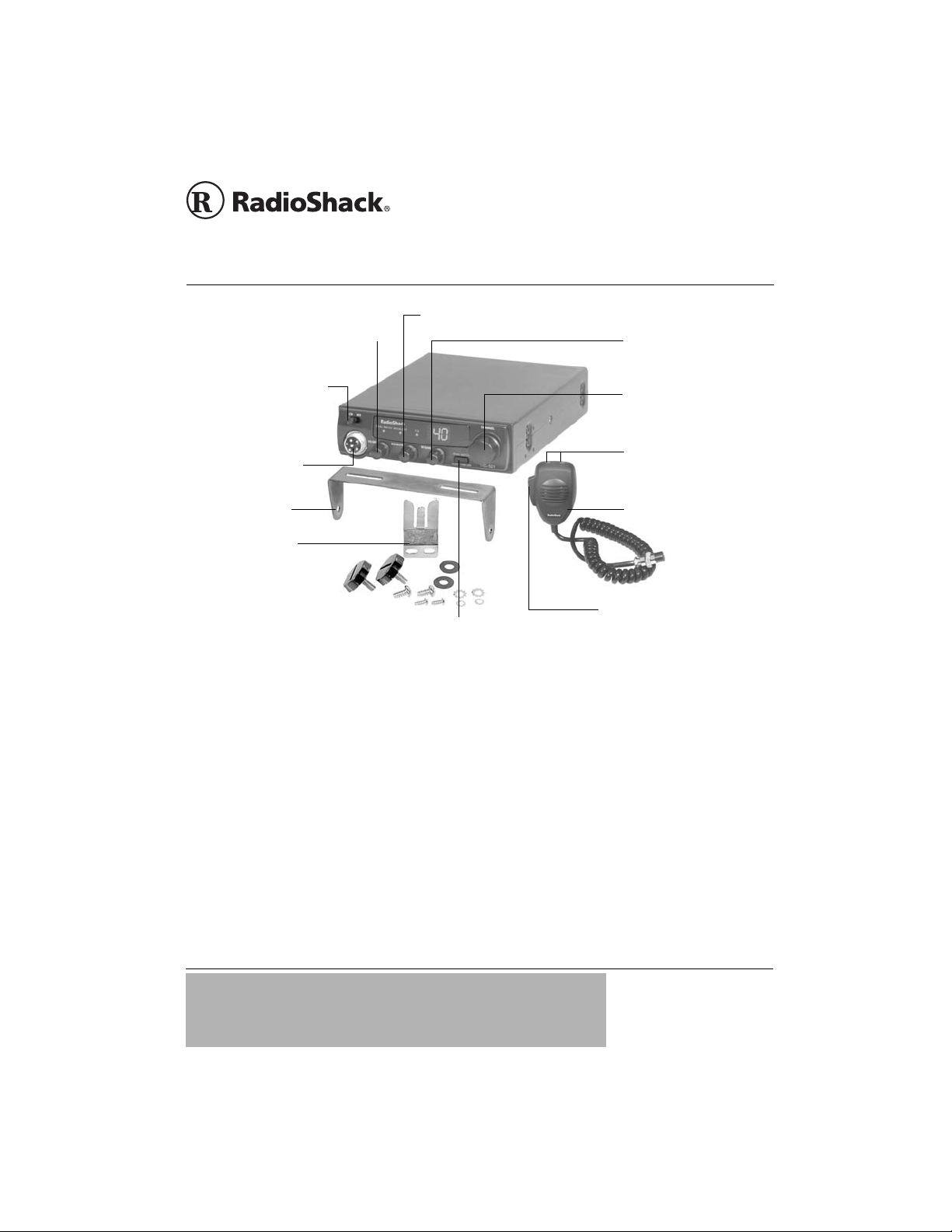
OFF/VOLUME — Rotate towards
V
a
t
SQUELCH — Rotate to reduce
SM
TRC521 CB Radio
OWNER’S MANUAL —
Please read before using this equipment.
OLUME to turn on your CB, and then
djust to desired listening level. Rotate
owards OFF to turn off you r C B .
B/WX — Slide to CB to
se and listen to citizen’s
and radio. Slide to WX to
isten to local and national
eather broadcasts.
onnect the supplied
icrophone here.
ounting Bracket
icrophone Holder
ounting hardware supplied
or the microphone holder
nd CB.
DUAL WATCH/ALERT TONE OFF —
Press to activate dual watch (see
Page 11), or to silence weather alert
tones (see Page 10).
background noise (CB sensitivity).
See Page 6.
PTT — Push to talk. Hold down
and talk into the microphone
while transmitting.
RF GAIN — Rotate to
improve signal reception in
strong signal areas. See
Page 6.
CHANNEL — Rotate to
tune to a channel.
UP/DN — Press or hold
down to scroll up or down
through channels.
Microphone
21-1711
Thank you for purchasing the RadioShack TRC521 CB Radio. It provides two-way
communication on the citizen’s radio band and lets you tune to local and national weather
service broadcasts. It provides the maximum legal power output for the greatest available
range, and a built-in PLL (phase-locked loop) frequency synthesizer to reduce congestion.
CB radio provides hours of fun and entertainment! Listen and talk to people from all over the
country while traveling, and make new friends along routes that you regularly travel. It is also a
great way to keep informed of local emergencies, such as traffic accidents, road blocks,
weather alerts and so on.
IMPORTANT
If an icon appears at the end of a paragraph, go to the box on that page
with the corresponding icon for pertinent information.
— Warning — Caution Ô — Note
o
!
!
© 2004 RadioShack Corporation.
All Rights Reserved.
RadioShack and R adio Sh ack .c om
are trademarks used by
RadioShack Corporation.
Page 2
CONTENTS
CB Radio Set u p ............ ............. 2
Attach the Microphone Holder 2
Mount the CB . ......................... 2
Connect the Microphone ......... 3
Connecting an Antenna .......... 3
Connecting to Vehicle
Battery Power ............ ............. 4
Connecting an Optional
External Speaker .................... 4
Using the CB as a Base Station . 5
Receiving and Transmitting ........ 6
Receiving ............................... 6
Transmitting ............................ 6
Using Common 10-Codes ...... 7
Tips for Using Your CB ............... 8
Business Use .......................... 8
Personal Use .......................... 8
Transmission Cou rt e sy ........... 8
Maximum Range ..................... 9
Reducing Noise ...................... 9
Listening to the Weather Band . 10
Using Digital Weather Alert ... 10
Using Dual Watch .................. 11
Replacing the Fuse ................ 11
Troubleshooting ....................... 12
Care ......................................... 12
Service and Repair ............... 12
FCC Information ....................... 13
Specificatio ns .................. ......... 14
Accessories .............................. 15
CB RADIO SETUP
Your CB’s display is prot ected during sh ipment by a piec e of
clear film. Carefully peel off thi s film befo re us ing your radio.
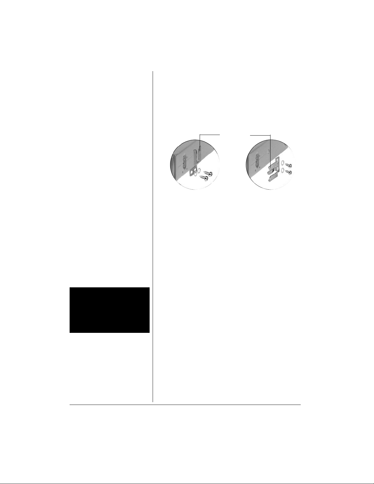
ATTACH THE MICROPHONE HOLDER
You can attach the microphone holder horizontally or
vertically to either side of your CB.
Vertical
To attach the microphone holder somewhere else, follow
these steps.
1. Use the microphone holder as a template to mark the
positions for the mounting screws at the desired
mounting location.
2. Drill a hole at the marked position. Do not drill into
anything behind the mounting surface.
3. Attach the microphone holder to the mounting surface
using the supplied (small) machine screws and
lockwashers.
Microphone
Holder
Horizontal
WARNING o
o
Mount the CB securely to avoid
damage to the CB or vehicle, and
to avoid injury to anyone in the
vehicle during sudden starts or
stops.
2
MOUNT THE CB
Find a convenie nt locati on in your vehicle to mount your CB.
If you are uncomfortable mounting the CB yourself, consult
with your vehicle service center or automotive dealer for
assistance.
Select a mounting location where:
• you can easily reach the CB.
• wires and cables are clear of the vehicle’s pedals or
• the CB is not directly in front of heating vents.
• all wires and cables can reach their connection points.
1. Use the mounting bracket as a template to mark the
o
other moving parts.
positions for the screws on the mounting surface.
Page 3
2. At the marked positions, dri ll a hole slightl y smaller than
M
K
the mounting screws. Do not drill into objects behind
the mounting surface.
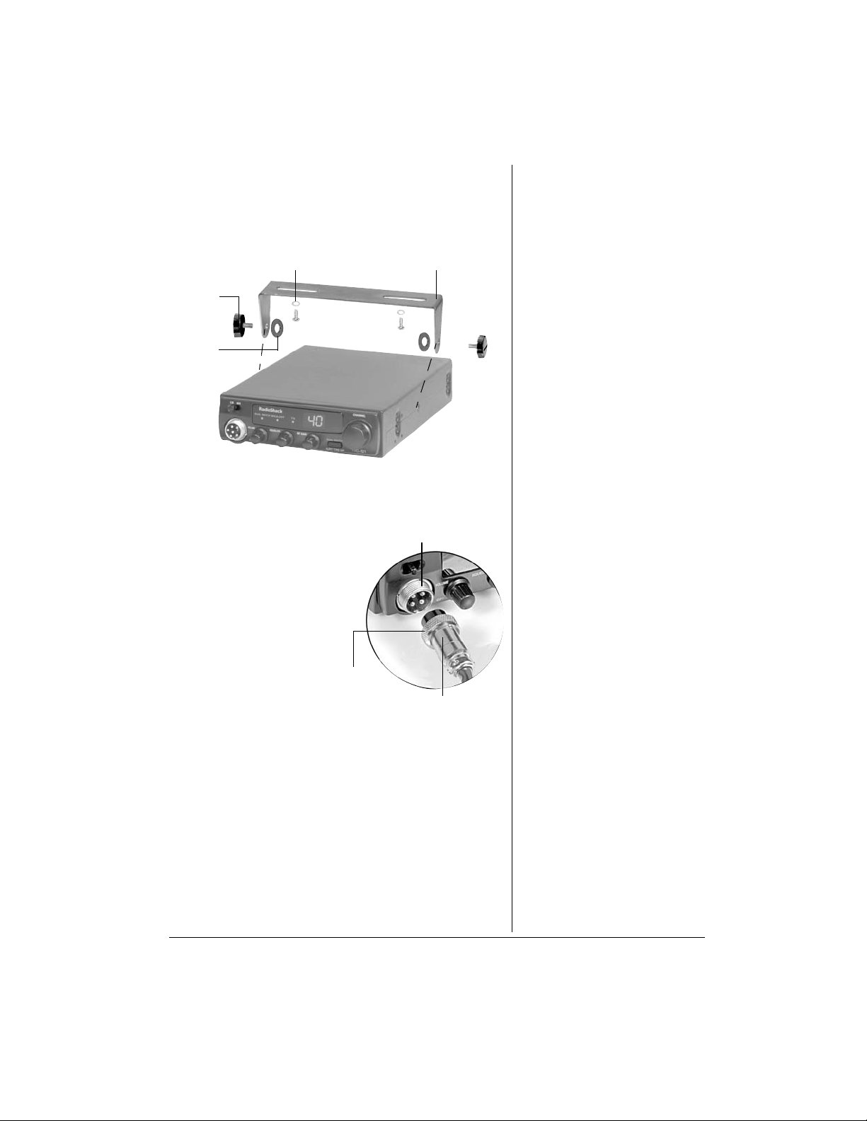
3. Secure the mounting bracket to the mounting surface
with the supplied screws and lockwashers.
Screws and Lockwasher s
ounting
nobs
Rubber
Washers
Mounting Bracket
4. Attach the CB to the mountin g bracket with the sup plied
rubber washers and mounting knobs.
Microphone
CONNECT THE MICROPHONE
Jack
1. Align the holes inside
the microphone’s plug
with the pins in the
microphone jack and
insert the plug.
2. Turn the plug’s locking
nut clockwise to secur e
it.
3. Slide the microphone
Locking
Nut
Microphone Plug
onto the holder.
4. To disconnect the microphone, unscrew the locki ng nut
and pull the microphone plug toward you. Do not pull
the microphone cable.
CONNECTING AN ANTENNA
To use this CB, you ne ed a mobile or base station antenna.
There are many types of antennas for CBs. Each type has
its own benefits, so choose the one that best meets your
needs. Your local RadioShack store sells a wide variety of
antennas. If you are using this CB as a base station, see
“Using the CB as a Base Station” on Page 5.
3
Page 4

CAUTION
• Avoid routing the cable next to
sharp edges or moving parts,
which might damage the cable.
• Do not run the cable next to
power cables or other radio
antenna cables.
• Do not run the cable through
the engine compartment or
other areas that produce
extreme heat.
Ô NOTE Ô
Do not connect the black wire to a
non-metallic (plastic) part, or to any
part insulated from the vehicle’s
chassis by a non-metallic part.
Dual band antennas provide optimum reception of CB and
WX channels. For mobile installations (car, boat), a nondirectional antenna provides the best CB reception. Mobile
antennas use your vehicle’s metal body as a ground plane.
If the CB is installed in a boat, your boat’s steel hull is used
as a ground plane. Without a steel hull serving as a ground
plane, you will not receive maximum efficiency. Before
using your CB in a boat, consult with your boat dealer
regarding an adequate grounding system.
Keep in mind that for the best performance you should
mount the antenna:
• as high as possible.
• as far as possible from sources
of electrical noise.
Black and red
POWER wires
• vertically.
1. Follow the antenna’s
instructions to mount it.
2. Route the antenna cable to
the CB radio and connect it
ANT. jack.
to the
ANT. Jack
Antenna Cable
CONNECTING TO VEHICLE BATTERY POWER
1. Connect the CB’s red POWER wire to a terminal in yo ur
vehicle’s fuse bo x that has power onl y when the igniti on
is in the ACC (accessory) or ON position.
2. Connect the CB’s black
the vehicle’s frame (chassis ground). Ô
POWER wire to a metal part of
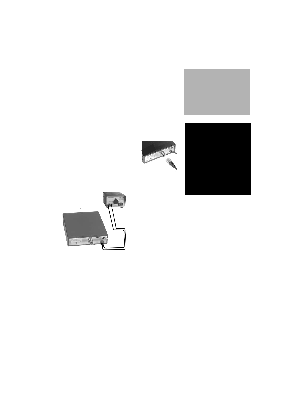
CONNECTING AN OPTIONAL
E
XTERNAL SPEAKER
You can conn ect an
external speaker to the
CB. Use an 8-ohm
1
speaker with a
/8-inch
(3.5-mm) plug. Insert the
speaker’s plug into the
EXT. SP. jack.
CB’s
4
EXT. SP. Jack
Page 5
USING THE CB AS A BASE
d
STATION
Although this CB is designed for mobile use, you can use it
as a base station with an AC power source. Your local
RadioShack store carries a wide selection of base station
antennas, coaxial antenna cable, connectors, and b ase
station power supplies. For base station installation, you
need the following items:
• a 12-volt DC power supply that can supply at least 1.5
amps.
• base station antenna.
• coaxial antenna cable and connectors.
1. Mount the base station antenna
as described in its owner’s
manual.
2. Connect the ante nna cable to the
ANT.
3. Connect the CB’s black POWER
wire to the negative (–) terminal
on the DC power supply.
o
jack on the back of the CB.
ANT.
Jack
DC Power Supply
Cable
CAUTION
Most 12-volt DC power supplies
plug into a standard AC outlet to
produce DC power. Before
connecting your CB to a 12-volt DC
power supply, read and follow the
instructions included with the
power supply.
WARNING o
o
Use extreme caution when you
install or remove a base station
CB antenna. If the antenna starts
to fall, let it go. It could contact
overhead power lines. If the
antenna touches a power line,
contact with the antenna, mast,
cable, or guy wires can cause
electrocution and death. Call the
power company to remove the
antenna. DO NOT attempt to do
so yourself.
Red wire connected
to + terminal
Black wire connecte
to – terminal
4. Connect the CB’s red
terminal on the DC power supply.
5. Connect the DC power supply to a standard AC outlet.
POWER wire to the positive (+)
5
Page 6

RECEIVING AND
TRANSMITTING
We recommend you try receiving transmissions before you
transmit.
RECEIVING
1. Rotate OFF/VOLUME towards OFF until it clicks to turn
off the CB.
Ô NOTE Ô
• Only rotate SQUELCH until the
hissing stops. If you continue to
rotate it clockwise, you will be
unable to receive any signals.
• You may want to purchase an
SWR (Standard Wave Ratio)
meter to measure your range
and signal strength. This will
enable you to adjust your
antenna for maximum range,
and determine the best position
for RF GAIN. See your SWR
meter owner’s manual for
instruction on how to use it.
2. Slide
3. Rotate
4. Rotate
5. Rotate
CB/WX to CB.
SQUELCH fully counterclockwise.
RF GAIN fully clockwise.
OFF/VOLUME clockwise to turn on the CB. The
display lights and the channel number appears. An
alert sounds if a weather alert signal is detected (see
“Using Digital Weather Alert” on Page 10).
6. To decrease CB sensitivity so you do not hear weak,
distant signals, slowly rotate
SQUELCH clockwise until
the hissing stops. To inc r ea se se ns iti vi t y a nd to re ce iv e
very weak signals, rotate SQUELCH counterclockwise.
Ô
7. Rotate
RF GAIN clockwise to optimize reception
(incoming signal strength). Or, rotate it
counterclockwise to decrease signal strength. Ô
8. To tune to a channel, rotate CHANNEL on the radio, or
press
UP or DN on the microphone. To quickly scroll
through channels in either direction, hold down
DN until you reach the desired channel.
9. Adjust
10. To turn off the CB, rotate
VOLUME to a comfortable listening level.
OFF/VOLUME
UP or
counterclockwise to OFF until it clicks.
TRANSMITTING
1. To transmit, hold down PTT on the mi cro pho ne. Hold
the microphone a bou t 2 –3 inc he s f r om y our mouth and
speak in a normal tone of voice.
transmission.
2. When you finish transmitting, release
6
TX lights to indicate
PTT. TX turns off.
Page 7

3. To turn off the CB, turn OFF/VOLUME counterclockwise
OFF until it clicks.
to
USING COMMON 10-CODES
Citizen’s Band operators have adopted 10-codes for
standard questions and ans wers. These code s permit faster
communication and better intelligibility in noisy areas. The
more popular codes follow:
Code Meaning
10-1 Receiving poorly.
10-2 Receiving well.
10-3 Stop transmitting.
10-4 OK, message received.
10-5 Relay message.
10-6 Busy, please stand by.
10-7 Out of service.
10-8 In service
10-9 Repeat message.
10-10 Transmission completed, standing by.
10-11 Talking too rapidly.
10-12 Visitors present.
10-13 Advise Weather/Road conditions.
10-17 Urgent business.
10-18 Anything for us?
10-19 Nothing for you. Return to base.
10-20 My location is____.
10-21 Call by telephone.
10-22 Report in person to____.
10-23 Please stand by.
10-25 Can you cont act____.
10-26 Disregard last information.
10-27 I am moving to channel____.
10-28 Identify your station.
10-32 I will give you a radio check.
10-33 Emergency traffic.
10-36 Correct time is____.
10-37 Wrecker needed at____.
10-38 Ambulance needed at______
10-41 Please turn to channel_____.
10-42 Traffic accident at_____.
10-43 Traffic tie-up at____.
10-50 Break channel.
10-62 Unable to copy; use telephone.
10-70 Fire at_____.
7
Page 8

This table lists the code meanings in the form of a
statement. They can also be phrased as questions. For
example, “10-6: Are you busy?”, “10-20: What is your
location?”.
TIPS FOR USING YOUR CB
Like most activities, CB radio has its customs and
courtesies. The following tips will help you get the most
enjoyment from your CB.
BUSINESS USE
• Truck drivers and delivery personnel can learn road
and traffic conditions and get assistance in locating
destinations. A CB is also good company on long road
trips.
• On construction crews, a CB quickly pays for itself
when you are calling for additional materials or
coordinating the activities of different work crews.
• For security officers, a CB is more than a convenience
— it is a must for both safety and efficiency.
PERSONAL USE
• Keep in touch with home while driving to work, to the
store, or to a social activity. Let your family know you
are tied up in traffic or that you will stop by the store on
the way home.
• If you are a two-car (or more) family, CBs are great for
communicating with family members while they are in
their cars.
• Contact friends or neighbors. F ind out “what’s
happening” or plan a get-together.
• Ever have car trouble o r run out of g as on the h ighway?
What an assurance it is to be able to c all for as sist anc e!
• Camping, fishing, and other sports are more fun with a
CB. Locate a buddy or find out “what ’s coo king” back at
camp.
TRANSMISSION COURTESY
• Wait for a p ause i n someone else’ s transm ission b efore
you ask for a break.
• If you do not receive an answer to your call after a
second attempt, sign off and wait several minutes
before trying again.
8
Page 9

• Do not hold down PTT when y ou are not talki ng. (This i s
called dead keying.)
• Assist callers with directions, information about road
conditions, and any other reasonable requests.
MAXIMUM RANGE
Your CB radio’s transmission range is generally line-ofsight. The maximum range and quality of CB transmissions
vary depending on the following conditions:
• the type and quality of antenna used.
• the heigh t of the antenna’s mounting location — the
higher the antenna, the better the signal’s range.
• the surrounding terrain — mountains and tall buildings
limit the range.
• weather conditions.
• the number of nearby CBs operating on the same
channel.
• standing wave ratio (SWR) between the antenna and
the CB.
REDUCING NOISE
Because your CB is ex cep tio nal ly qu iet, any noise you hear
is probably from an ex ternal source in your vehicle, such as
the alternator, another radio, or spark plugs. You can
determine the noise source by turning off the engine and
operating the CB with your vehicle’s ignition set to ACC. If
the noise is red uced, the problem is in y our vehi cle’s ig nition
or electrical system.
To reduce or e liminate such noise:
• Make all CB power and antenna wires as short as
possible.
• Keep the power wires away from the antenna wires.
• Be sure the chassis ground connection is secure.
• Replace old ignition wires with new, high-voltage,
noise-suppression wires.
• Install noise sup pre ss ors on y our s p a r k p lug s, o r ins t al l
new spark plugs that have built-in noise suppressors.
• If problems persist, ch eck your alternat or/generator and
regulator gauges. You can reduce the noise from the se
sources by us ing bypass capacitors at the various
output voltage points.
9
Page 10

Ô NOTE Ô
.
• PTT does not work when
CB/WX is set to WX. You can
only send transmissions when
in CB mode.
• You cannot transmit while WX/
ALERT flashes in CB mode.
• The alert tones for a Test and
EAT (Emergency Action
Termination) sound very similar.
We suggest you switch to WX
mode immediately to listen to
the weather broadcast.
• Because of atmospheric
conditions, you may receive
signals that do not contain
information relevant to the
emergency level. This is normal
• The radio sounds an alert
regardless of the channel
setting.
• The CB will not sound an alert
while you are transmitting.
• If you are in a rural or fringe
area, your radio might be
triggered by an alert broadcast
in one area, but not be triggered
if you travel to another area
(even close by).
LISTENING TO THE WEATHER
BAND
The National Oceanic and Atmospheric Administration
(NOAA) broadcasts local forecast and regional weather
information on one or more of seven channels in the US.
We have pre-programmed your CB with all seven of these
frequencies.
Channel Frequency (MHz)
WX1 162.400
WX2 162.425
WX3 162.450
WX4 162.475
WX5 162.500
WX6 162.525
WX7 162.550
To listen to a weather broadcast or alert, slide
Rotate
CHANNEL to select a frequency. Ô
To verify reception, your radio must receive a test or
emergency alert broadcast. The National Weather Service
broadcasts a test alert every week. To find the specific test
schedule in your area, contact your local NOAA or National
Weather Service office.
USING DIGITAL WEATHER ALERT
When in CB mode, the rad io automat ically s ounds an a lert if
a weather alert signal is detected. This is especially useful
when your area is expecting severe weather condition s .
When your local weather station broadcasts a severe
weather alert, the CB sounds a tone corresponding to the
alert type and
Action T erminati on)
WX/ALERT lights.
Alert Type You Hear
Warning Continuous short beeps
Watch
Advisory
Test
EAT (Emergency
Three short beeps and a 2
second pause (repeats)
Two short beeps and a 2
second pause (repeats)
One short beep and a 3 second
pause (repeats)
One short beep and a 3 second
pause (repeats)
CB/WX to WX.
Ô
10
Page 11

To silence the alert tones, press ALERT TONE OFF.
Fuse Holders
WX/ALERT fl ashes un til you swi tch to W X mode and l isten to
the broadcast. Or press
WX/ALERT stops flashing. Ô
PTT to silence the alert tones so
To reduce the alert tone levels for subsequent alerts, hold
ALERT TONE OFF for about two seconds while
down
WX/ALERT flashes. The tone stops and WX/ALERT flashes
slowly. If the radio receives a new weather alert, three
low-level, short beeps sound (regardless of alert type).
To listen to the weather when an alert is received, slide
CB/WX to WX. WX/ALERT turns off.
USING DUAL WATCH
You can set your radio to constantly monitor for emergency
(Channel 9) signals. If a n em erge nc y si gn al is rec eiv ed , the
CB radio automatically tunes to Channel 9 so you can hear
the broadcast. When finished, the radio returns to the
previous station. This feature only works in CB mode.
Ô NOTE Ô
You cannot transmit while
WX/ALERT flashes in CB mode.
To activate dual watch, press
lights. Press
DUAL WATCH again to deactivate.
DUAL WATCH. DUAL WATCH
REPLACING THE FUSE
The CB’s in-line fuse protects it from power surges and
short circuits. When replacement is required, use a 2-amp,
fast-acting glass fuse, available at your local RadioShack
store.
1. Make sure the vehicle and CB are turned off.
2. Hold the fuse holder at both ends, push the ends
together , twi st one end counterc lockwis e, and p ull them
apart.
Fuse
3. Remove the old fuse and inspect its cond iti on. If it is
blown, insert a new one of the same type and rating. If
it is not blown, reinsert it.
4. Push the fuse holder en ds together and twist one end
clockwise.
CAUTION
Do not use a fuse with ratings
other than those specified here.
Doing so will make your CB
susceptible to electrical damage.
11
Page 12

TROUBLESHOOTING
We do not expect you to have any problems with your CB,
but if you do, the following suggestions might help.
Symptom Suggestion
Make sure POWER is on.
Make sure SQUELCH is adjusted
properly.
Be sure RF GAIN is fully clockwise.
Trouble receiving.
Trouble transmitting.
The CB is completely
inoperable.
If these tips do no t solve the pr oblem, do not atte mpt repairs
or adjustments yourself. The CB should be serviced only by
a qualified radio technician. If you still have problems, take
your CB to your local RadioShack store for assistance.
Make sure the CB is set to an operating
channel.
Make sure the microphone is securely
connected.
Check for a good antenna connection.
Make sure the antenna cable is securely
connected to the radio.
Make sure the antenna is fully extended.
Make sure all connections are secure
and free of corrosion.
Make sure CB/WX is set to CB.
Check the DC power cord and in-line
fuse.
Replace the fuse. See “Replacing the
Fuse” on Page 11.
12
CARE
Keep the CB dry; if it gets wet, wipe it dry immediately. Use
and store the CB o nly in room temperature environments. If
used in a boat, do n ot expos e CB to e xtreme heat or cold fo r
prolonged periods of time. Handle the CB carefully; do not
drop it. Keep the CB away from dust and dirt, and wipe it
with a damp cloth occasionally to keep it looking new.
SERVICE AND REPAIR
If your CB is not performing as it shou ld, take it to yo ur local
RadioShack store for assistance. To locate your nearest
RadioShack, use the store locator feature on RadioShack's
website (www.radioshack.com), or call 1-800-The Shack
(843-7422) and follow the menu options. Modifying or
tampering with the CB's internal components can cause a
malfunction and might invalidate its warranty and void your
FCC authorization to operate it.
Page 13

FCC INFORMATION
The Federal Communications Commission (FCC) does not
require you to have a license to operate this CB. However,
the FCC does require that you read and know Part 95 of
FCC Rules. These rul es app ly to th e op erat ion of a Class D
CB.
Warning: Do not open your CB to make any internal
adjustments. Any internal adjustments can be made only by
an authorized service tec hni ci an.
Unauthorized interna l ad justment s an d/or mod ificat ions c an
lead to illegal operat ion as defin ed by Part 95 of FCC R ules.
Such illegal operation can lead to very serious
consequences.
Your CB might cause TV or radio interference even when it
is operating properly. To determine whether your CB is
causing the interfere nce, turn off your CB. If th e interfere nce
goes away, your CB is causing it. Try to eliminate the
interference by:
• moving your CB away from the receiver
• connecting your CB to an outlet that is on a different
electrical circuit from the receiver
• contacting your local RadioShack store for help
If you cannot eliminate the interference, the FCC requires
that you stop using your CB.
This device complies with Part 15 of the FCC Rules.
Operation is subject to the following two conditions: (1) this
device may not cause harmful interference, and (2) this
device must accept any interference received, including
interference that may cause undesired operation.
13
Page 14

SPECIFICATIONS
RECEIVER
Frequency Response (1 kHz, 0 dB Reference)
Lower, at 450 Hz ................................................................... –3 dB
Upper, at 2500 Hz ................................................................. –3 dB
Intermediate Frequency
First IF ......................................................................... 10.695 MHz
Second IF .......................................................................... 455 kHz
Maximum Sensitivity ................... ............................................ 1 µV
Sensitivity for 10 dB S/N ........................................... 1 µV or better
AGC Figure of Merit
50 mV for 10 dB Change in Audio Output ............................. 90 dB
Overload AGC Characteristics (from 50 mV to 1000 mV) ....... 4 dB
Adjacent Channel Selectivity ................................................. 55 dB
Image Rejection ................................... Typically better than 60 dB
IF Rejection ............................................................. 65 dB or better
Maximum Audio Output Power .................... ...... 4 Watts at 8 ohms
Squelch Range .............................. Adjustable from 0.5 µV to 1 mV
Receive Battery Drain ..................................... 280 mA to 1500 mA
(from No Signal to Maximum Output)
TRANSMITTER
Frequency Tolerance ...................................................... ±0.0005%
Maximum Output Power ........ 4 Watts (maximum allowed by FCC)
Spurious Emission ................................................. –65 dB or better
Transmit Battery Drain .................................. 1270 mA to 1870 mA
(from No Modulation to 80% Modulation Limit)
Modulation Frequency Response (1 kHz, 0 dB Reference):
Lower, at 450 Hz ................................................................... –3 dB
Upper, at 2.5 kHz .................................................................. –3 dB
Modulation Type and Capacity .................................... A3 and 85%
Microphone Sensitivity ........................... 5 mV for 50% Modulation
GENERAL
Channels ..................................................................................... 40
Frequency Range ................................ 26.965 MHz to 27.405 MHz
Frequency Control ....................... Phase-Locked Loop Synthesizer
Operating Temperature Range ............................... –22°F to 122°F
Power Requirements ........................... 13.8V DC (12–16 volts DC,
Input Power ............................................. 7.5 W (Reference Value)
Antenna ............................................. 50 Ohm (Coaxial Connecto r)
Microphone .......................................................... Condenser Type
Negative Ground)
14
Page 15

Internal Speaker ................................................... 16 Ohm, 5 Watts
Dimensions (HWD) ................................. 1
Weight ......................................................................... 2 lbs (930 g)
Specifications are typical; individual units might vary. Specifications
are subject to change and improvement without notice.
9
/16 x 59/16 x 75/16 inches
(40 mm x 142 mm x 185 mm)
ACCESSORIES
Depending on how and where you plan to use your CB
radio, the following accessories can be used with your CB
radio for enhanced fuctionality and power. Visit your local
RadioShack store or go to www.radioshack.com to browse
for a variety of CB accessories.
CB Antenna
SWR Meter
8-ohm External Speaker
12V DC Power Supply
Base Station Antenna
Coaxial Antenna Cable and Connectors
Antenna Connectors
2-Amp Glass Fuse (for fuse replacement)
15
Page 16

Limited Ninety-Day Warranty
This product is warrant ed by RadioSh ack against manufa cturing defe cts in material and wor kmanship under normal use for ninety (90) day s from the date of purchase from Radio Shack companyowned stores and authorized RadioShack franchisees and dealers. EXCEPT AS PROVIDED
HEREIN, RadioShack MAKES NO EXPRESS WARRANTIES AND ANY IMPLIED WARRANTIES,
INCLUDING THOSE OF MERCHANTABILITY AND FITNESS FOR A PARTICULAR PURPOSE,
ARE LIMITED IN DURATION TO THE DURATION OF THE WRITTEN LIMITED WARRANT IES
CONTAINED HEREIN. EXCEPT AS PROVIDED HEREIN, RadioShack SHALL HAVE NO LIABILITY OR RESPONSIBILITY TO CUSTOMER OR ANY O THER PERSON OR ENTITY WITH RESPECT TO ANY LIABILITY, LOSS OR DAMAGE CAUSED DIRECTLY OR INDIRECTLY BY USE
OR PERFORMANCE OF THE PRODUCT OR ARISING OUT OF ANY BREACH OF THIS WARRANTY, INCLUDING, BUT NOT LIMITED TO, ANY DAMAGES RESULTING FROM INCON VENIENCE, LOSS OF TIME, DATA, PROPERTY, REVENUE, OR PROFIT OR ANY INDIRECT,
SPECIAL, INCIDENTAL , OR CONSEQUENTIAL DAMAGES, EVEN IF RadioSh ack HAS BEEN ADVISED OF THE POSSIBILITY OF SUCH DAMAGES.
Some states do not allow limitations on how long an implied warranty lasts or the exclusion or limitation of incidental or conseque ntia l dama ge s, so the abo ve l imitation s or e xclusio ns ma y not a ppl y to
you.
In the event of a pr oduct defect dur ing the warranty p eriod, take the pro duct and the R adioShack
sales receipt as proof of purchase date to any RadioShack store. RadioShack will, at its option, unless otherwise prov ided b y l aw : ( a) correct the d efe ct b y p rod uct re pair wi t hou t ch ar ge for par ts and
labor; (b) replace the product wi th one of the same or similar design; or (c) refund the purch ase
price. All replaced parts and products, and products on which a refund is made, become the property
of RadioShack. New or recond itioned parts an d products may be used in the perfo rmance of w arranty service. Repaired or re placed parts and products are warr anted fo r the rem ainder of the original warranty period. Yo u will be charged for repair or re placement of the product made after the
expiration of the warranty period.
This warranty does not cov er: (a) da ma ge or fail ur e cau sed by or att ri bu table to acts of Go d, ab use,
accident, misuse, improper or abnormal usage, failure to follow instructions, improper installation or
maintenance, alteration , lightning or other incidence of excess voltage or current; (b) any repairs
other than those provided by a RadioShack Authorized Service Facility; ( c) consumables such as
fuses or batteries; (d) c osmetic d amage ; (e) tr anspor tation, s hipping o r insu rance c osts; or (f) c osts
of product removal, installation, set-up service adjustment or reinstallation.
This warranty gives you specific legal rights, and you may also have oth er rights which vary from
state to state.
RadioShack Customer Relations, 200 Taylor Street, 6th Floor, Fort Worth, TX 76102
12/99
01A04
Printed in China
21-1711
UTZZ01368ZZ
 Loading...