

RadioShack TRC-498 Owners Manual
21-159 8.fm Page 1 Thursday, Au gust 5, 1999 10:52 AM
40-Channel CB Mobile Transceiver
with Digital Signal Processor
Cat. No. 21-1598
OWNER’S MANUAL
Please read before using this equipment.
TRC-498

y Sy
g
y
g
y
g
g
21-159 8.fm Page 2 Thursday, Au gust 5, 1999 10:52 AM
FEATURES
Your RadioShack TRC-498 40Channel CB Mobile Transceiver is a
breakthrough in CB design technology. It includes a DSP (Digital Signal
Processor) circuit for improved audio
quality, which reduces background
noise and virtually eliminates the
whines and whistles commonly heard
on crowded CB frequencies.
Your CB also has these advanced features:
DSP Switch and Indicator
— turns
the DSP circuit on and off and shows
the on/off status of the circuit.
Phase-Locked Loop (PLL) F req uenc
nthesizer
— provides highly ac-
curate and stable tuning.
Two Built-In Ceramic Filters
— ensure superior channel selectivity and
freedom from adjacent channel interference.
Automatic Modulation Control
—
prevents the transmitter signal from
over-modulating and distorting.
Automatic Noise Limiter
— reduces
impulse-type noises while receiving.
Lar
e, Illuminated, Digital Displa
— clearly shows the channel number.
Emer
ency Channel Switch
— lets
you quickly switch to Channel 9 so you
can monitor or report emergency situations.
Built-In PA (Public Address) Ampli-
— lets you use your CB as a public
fier
address system when you add an optional PA speaker.
Base Station Capabilit
— lets you
use the transceiver as a base station
powered from a standard AC outlet
(with an optional power supply and
base station antenna).
RF Gain Control
— lets you adjust the
receiver gain to match the strength of
the received signal.
4-Step RX Si
nal/TX Power Meter
—
shows the strength of the incoming
and outgoing transmissions.
External Speaker Jack
— lets you
connect your CB to an external speaker.
Noise Reduction Switch
— lets you
select one of two available noise reduction modes.
Universal Mountin
Bracket
— lets
you mount your CB securely in your
vehicle or on a table or shelf in your
home.
© 1996 Tandy Corporation.
RadioShack i s a trademark used by Tandy Corporation.
Powerhorn is a registered trademark used by Tandy Corporation.
All Rights Reserv ed .
2

21-159 8.fm Page 3 Thursday, Au gust 5, 1999 10:52 AM
Note: To use this CB, you must connect a mobile or base station antenna.
Your local RadioShack store has a
wide variety of antennas. For more information, see “Conne cting an Antenna” on Page 6.
We recommend you record your CB’s
serial number here. The number is on
the CB’s back panel.
Serial Number _________________
FCC INFORMATION
The Federal Communications Commission (FCC) does not require you to
have a license to operate this CB radio. However, you must know Part 95
FCC Rules
of
operation of a Class D citizen’s band
transceiver. We enclosed a copy of
Part 95 with your CB radio.
Warning: Do not open the CB radio to
make any internal a djustments. A CB
radio is set up to transmit a regulated
signal on an assigned frequency . It is
against the law to alter or adjust the
settings inside the unit to exceed these
limitations.
. It explains the proper
To be safe and sure:
• Never open your CB radio’s case.
• Never change or replace a nything
in your CB radio.
Your CB radio might cause T V or radio interference even when it is operating properly. To determine whether
your CB radio is causing the interference, turn off your CB radio. If the interference goes away, y our CB radio
is causing it. Try to elimi nate the interference by:
• Moving your CB radio away from
the receiver
• Contacting your loca l RadioShack
store for hel p
If you cannot eliminate the interference, the FCC requires that you stop
using your CB radio.
This device complies with Part 15 of
FCC Rules
following two conditions: (1) this device may not cause harmful interference, and (2) this device must accept
any interference received, including
interference that may cause undesired
operation.
. Operation is subject to the
Any adjustments to a CB radio must be
made by a qualified technician using
the proper test equipment.
3

g
21-159 8.fm Page 4 Thursday, Au gust 5, 1999 10:52 AM
CONTENTS
Installation ............................................................................................................ 5
Attaching the Microphone Holder .................................................................... 5
Mounting the Transceiver ................................................................................ 5
Connecting an Antenna ................................................................................... 6
Connecting the Microphone . ............................................................................ 7
Connecting Optional Speakers ........................................................................ 8
Using an External CB Speaker ................................................................. 8
Connecting a PA Speaker ......................................................................... 8
Using Vehicle Battery Power ........................................................................... 9
Using the Transceiver as a Base Station ......................................................... 9
Operation ............................................................................................................ 11
Receiving Transmissions and Adjusting Squelch .......................................... 11
Transmitting ................................................................................................... 12
Using the Digital Signal Processor ................................................................ 13
Selecting the Emergency Channel ......................................... ....... ....... ....... .. 13
Using the PA Amplifier ................................................................................... 14
Operational Hints ............................................................................................... 15
Common Uses for a CB ................................................................................. 15
Personal Uses ......................................................................................... 15
Business Uses ........................................................................................ 15
Maximum Range . .......................................................................................... 16
Transmission Courtesy .................................................................................. 16
Using Common 10-Codes ............................................................................. 17
Troubleshootin
Reducing Noise ............................................................ .......... ....... .. .......... .... 20
Care and Maintenance ....................................................................................... 21
Replacing the Fuse ........................................................................................ 22
Specifications ..................................................................................................... 23
4
................................................................................................. 18
21-159 8.fm Page 5 Thursday, Au gust 5, 1999 10:52 AM
INSTALLATION
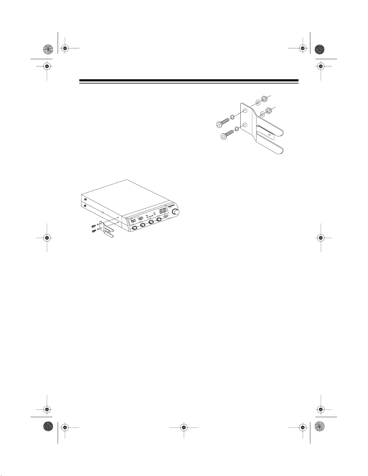
ATTACHING THE
MICROPHONE HOLDER
You can connect the microphone holder to either side of the transceiver or to
another location in your vehicle.
To attach the holder to either side of
the transceiver, secure the holder to
the side using the supplied screws and
lock washers.
If you cannot reach behi nd
Note:
the mounting surface to attach the
nuts on the mac hine screws, use
the supplied 3 mm plain washers
and self-tapping screws.
MOUNTING THE
TRANSCEIVER
To attach the holder to another location in the vehicle, such as t he dashboard, follow these steps.
1. Using the holder as a template,
mark the positions for the mounting screw holes at the desired
location.
2. At each marked position, drill a
hole slightly smaller than the supplied mounting screws.
Caution:
into anything behind the mounting surface.
3. Attach the holder at the mounting
location using the supplied 3 mm
machine screws, spring washers,
plain washers, and nuts.
Be careful not to drill
The most common mounting location
for this CB is under a vehicle’s dashboard. However, if you use the TRC498 as a base station, you can place it
on a desk, shelf, or table (see “Using
the Transceiver as a Bas e Station” on
Page 9).
If you are mounting the CB in a vehicle, choose a location where:
• You can easily reach the CB.
• Wires and cables are c lear of the
vehicle’s pedals or other moving
parts.
• The CB is not directly in front of
heating vents.
• All wires and cables can reach
their connection points.
5
21-159 8.fm Page 6 Thursday, Au gust 5, 1999 10:52 AM
Caution: If you use t he CB in a vehicle, mount it securely to avoid damage
to the CB or vehicle or injury to anyone
in the vehicle during sudden starts or
stops.
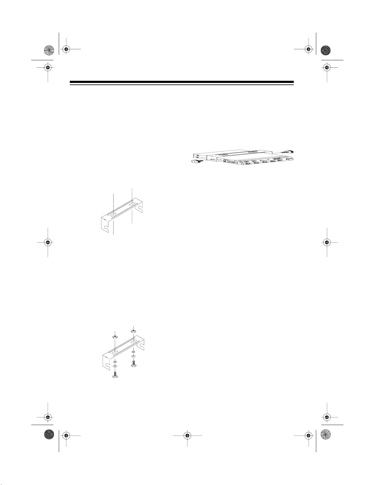
Follow these steps to mount the CB
using the supplied hardware.
1. Using the mounting bracket as a
template, mark the positions for
the screw holes on the mounting
surface.
2. In each marked location, drill a
hole slightly smaller than the supplied mounting screws.
Caution: Be careful not to drill
into objects behind the mounting
surface.
3. Mount the bracket to the mounting
surface with the supplied 6 mm
bolts, spring washers, plain washers, and nuts.
nuts on the bolts, use the supplied
6 mm self-tapping screws and
plain washers to secure the
bracket.
4. Attach the CB to the mounting
bracket using the suppl ied rubber
washers and mounting knobs.
CONNECTING AN
ANTENNA
There are many diff erent types of CB
antennas for mobile CBs. Each type
has its own benefits, so choose the
one that best m eets your n eeds. Y our
local RadioShack store sells a wide variety of antennas.
Note: If you are using this CB as a
base station, see “Using the Transceiver as a Base Station” on Page 9.
When you choose an antenna, keep in
mind that, for the best performance,
you should mount the antenna:
Note: If you cannot reach behind
the mounting surface to attach the
6
• As high as possible on the vehicle
• As far as possible from s ources of
electrical noise
• Vertically
21-159 8.fm Page 7 Thursday, Au gust 5, 1999 10:52 AM
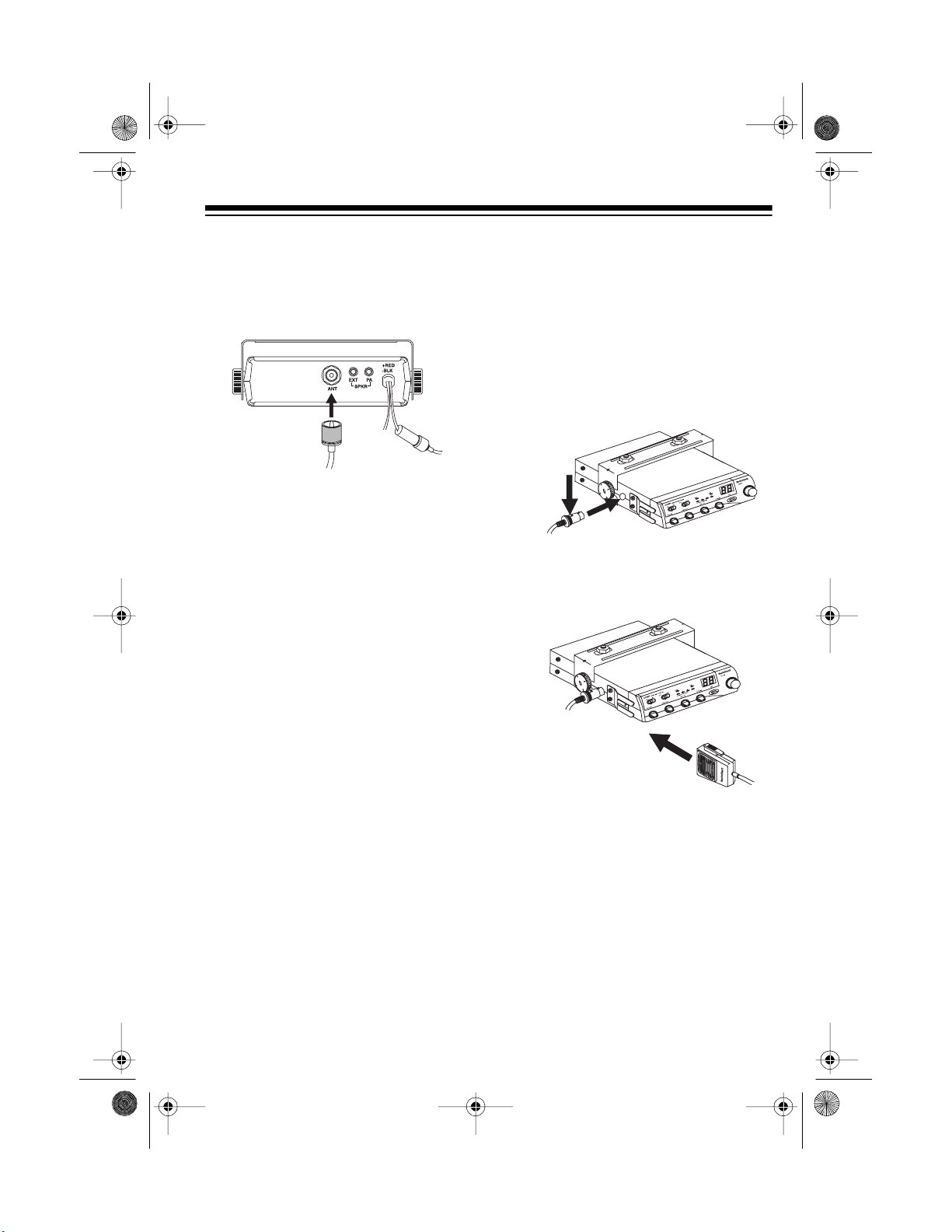
Once you choose an antenna, follow
its mounting instructions. Then route
the cable to the transceiver and connect the cable to the
back of the transceiver.
To Antenna
Cautions:
• Avoid routing the cable next to
sharp edges or moving parts,
which might damage the cable.
• Do not run the cable next to power
cables or other radio antenna cables.
• Do not run the cable through the
engine compartment or other
areas that produce extreme heat.
ANT
jack on the
CONNECTING THE
MICROPHONE
1. Press the tab on the side of the
supplied microphone’s plug and
insert the plug into the microphone jack on the side of the
transceiver. Be sure the tab is
aligned with the jack’s notch.
2. Slide the microphone onto the
microphone holder.
To achieve your radio’s maximum
range, adjust the antenna’s Standing
Wave Ratio (SWR) using an SWR
meter (not supplied).
Follow the instructions supplied with
the SWR meter and antenna to adjust
your antenna’s SWR to the lowest possible value. SWR values of 2 .0:1 are
generally acceptable, with readings of
1.5:1 or lower being more desirable.
Caution:
phone from the transceiver, press the
tab on the side of the plug. Then pull
out the plug. Never pull on the microphone cable.
To disconnect the micro-
7
21-159 8.fm Page 8 Thursday, Au gust 5, 1999 10:52 AM
CONNECTING
OPTIONAL SPEAKERS
You can connect your transceiver to an
external CB speaker and/or a PA (public address) speaker.
Note:
When you connect an external
or PA speaker, the CB’s internal
speaker disconnects.
Using an External CB
Speaker
The external speaker you use with the
transceiver should have an impedance
of 8 ohms and be able to handle 3 to 10
watts of power, such as RadioShack
Cat. No. 21-549. The speaker cable
must have a
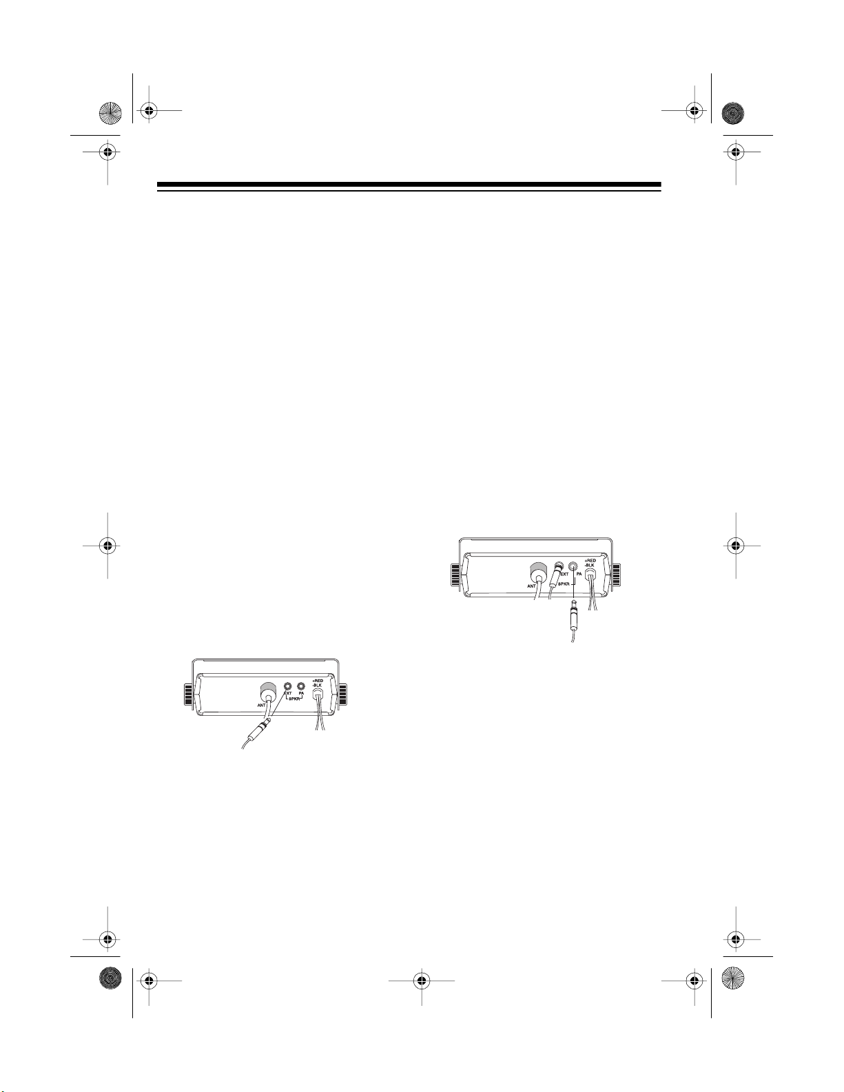
To connect the external speaker to the
transceiver, insert the speaker cable’s
plug into the
back of the CB.
1
/8-inch plug.
EXT SPKR
jack on the
Connecting a PA Speaker
The PA speaker should have an impedance of 8 ohms and be able to handle at least 5 watt s of power, such as
any of the RadioShack Powerhorn
ries speakers. The speaker cable must
have a
1
/8-inch plug.
If your PA speaker does not already
have a
1
/8-inch plug, we recommend
connecting the PA speaker with a
phono plug-to-wire cab le, available at
your local RadioShack store.
To connect the PA speaker to the
transceiver, insert the speaker cable’s
plug into the
P A SPKR
jack on the back
of the CB.
Power
Connections
To an 8-ohm,
5-Watt or Greater
Speaker
®
se-
Note:
The speaker should be at least 6
feet from the CB.
To an 8-ohm,
3- to 10-Watt
Speaker
Power
Connections
8
 Loading...