

Page 1
21-1574.fm Page 1 Thursday, May 13, 1999 4:03 PM
Cat. No. 21-1574
OWNER’S MANUAL
Please read before using this equipment.
TRC-446
Deluxe 4 Watt 40-Channel
Mobile CB Radio
with Weather Alert and ACE
Page 2

21-1574.fm Page 2 Thursday, May 13, 1999 4:03 PM
FEATURES
Your RadioShack TRC-446 Deluxe 40Channel Mobile CB Radio w ith Weather
Alert is a high perfo rmance C B that also
lets you tune to local and national
weather service broadc asts. This CB is
perfect for recreational, business, or
emergency use. Y ou c an ca ll o ther peo ple who have CBs at home, in their vehicles, or at camp sites. You can also
connect optional equ ipment to your CB,
such as an external speaker which creates a PA system; or a DC power supply
and base station an tenna to use it as a
base station in your home.
Your CB has these features:
ACE (Audio Clarity Enhancer)
— suppresses noise levels while leaving the
signal intact during reception. During
transmitting, it enhan ces the signal , pro viding you with a si gnificant reduc tion in
reception and transmission noise.
NOAA 7-Channel WX Band Receiver
— lets you tune to seven national
weather service frequen cies which provide local weather conditions and forecasts.
WX/Alert Indicator
— shows the CB is
ready to receive and indicates the reception of a weather alert
Built-In SWR Meter
— helps you tune
your antenna system to optimize your
CB's performance.
RF Gain Control
— lets you adjust reception to match the strength of the received signal.
Convenient On-Microphone Channel
Up/Down Controls —
let you quickly
scan the band for communications.
CH-9/NOR/CH-19 Switch
— lets you
quickly tune to e mergency Channel 9 or
Channel 19 without using th e rotary tuning control.
Screw-On Microphone Connector
—
ensures rugged operation and long life.
PLL (Phase-Locked Loop) Frequency
Synthesizer
— uses a precise frequency reference crystal to provide reliable
and exact tuning.
Two Ceramic Filters
— provide superior channel sel ectivity and prevent adjacent-channel interference.
Specialized Squelch Circuit
— compensates for fading signals and eliminates signal chopping during reception.
Last-Channel Memory
— tunes to the
last selected channel each time you turn
on the radio.
Lighted SWR/RF/Signal Meter
— displays the signal stre ngth and the standing wave ratio (SWR).
Digital Channel Display
— makes the
selected channel easy to see.
1999 Tandy Corporation.
©
RadioShack is a registered trademark used by Tandy Corporation.
All Rights Reserved.
2
Page 3
21-1574.fm Page 3 Thursday, May 13, 1999 4:03 PM
Noise Blanking
occasionally gener ated by nearby electrical motors or automotive i gnition systems.
CB/WX/PA Switch
select among normal CB operation,
weather mode, or public address mode.
RX/TX Indicator
CB is transmitting or receiving.
S/RF/SWR/CAL Switch
quickly change the display of the RF/
Signal Meter to s how radio input/output
signal strength, the stand ing wave ratio
of the antenna, or SWR calibration data.
Universal Mounting Bracket
you mount your CB s ecurely in you r vehicle.
Note:
To use this CB, you n eed a mobile or base station antenna (not supplied). Your local Radio Shack store has
a wide variety of antenna s. For mo re information, see “Installing an Antenna”
on Page 7.
We recommend you record your CB's
serial number here. The number is on
the CB's back panel.
Serial Number__________________
— reduces the noise
— lets you quickly
— shows whether the
— lets you
— lets
FCC INFORMATION
The Federal Communications Commission (FCC) does not requi re yo u to h av e
a license to operate this CB. However,
the FCC does require that you read and
know Part 95 of
apply to the operation of a Class D CB.
We have provided a copy of these regulations with your CB.
Warning:
any internal adjustments. Any internal
adjustments can be made only by an authorized service technician.
Unauthorized internal adjustments and/
or modifications can lead to illegal operation as defined by Part 95 of FCC
Rules. Such illegal operation can lead to
very serious con sequences. To be safe
and sure:
• Never open your CB's case.
• Never modify your CB.
Your CB might cause TV or radio interference even when it is o perating properly. To determine whether your CB is
causing the interference, turn off your
CB. If the interference goe s away, your
CB is causing it. Try to eliminate the interference by either moving your CB
away from the receiver or contacting
your local RadioShac k store for help. If
you cannot eliminate the interference,
the FCC requires that you stop using
your CB.
FCC Rules
Do not open your CB to make
. These rules
3
Page 4
21-1574.fm Page 4 Thursday, May 13, 1999 4:03 PM
CONTENTS
Installation ............................................................................................................... 5
Mounting the TRC-446 ....................................................................................... 5
Connecting the Microphone ................................................................................ 6
Installing an Antenna ................................... ...... ....... ...... .................................... 7
Selecting an Antenna ................................................................................... 7
Connecting an Antenna ............................................................................... 7
Using Vehicle Battery Power .............................................................................. 7
Using the CB as a Base Station ......................................................................... 8
Connecting Optional External Speakers ......................... ....... ...... ....... ...... ...... .... 8
External CB Speaker ................................................................................... 8
Public Address Speaker ............................................................................... 9
Adjusting the Standing Wave Ratio .................................................................... 9
Standing Wave Ratio Guidelines ...................................................................... 10
Standing Wave Ratio Performance ............................................................ 10
A Quick Look at the Controls ............................................................................... 11
Operation ............................................................................................................... 12
Changing Channels Using the Controls on the Microphone ............................. 13
Listening to Weather Broadcasts ...................................................................... 13
Weather Alert .................................................................................................... 14
Using the Public Address Function ................................................................... 14
CB Operation Tips ................................................................................................ 15
Business Uses .................................................................................................. 15
Personal Uses .................................................................................................. 15
CB Courtesy ...................... ...... ....... ...... .............................................. ...... ...... .. 15
Using Common 10-Codes .................................................................................... 16
Maximum Range .............................................................................................. 17
Troubleshooting .................................................................................................... 18
Care and Maintenance .......................................................................................... 19
Specifications ......................... .......................... .......................... ......................... .. 21
4
Page 5
21-1574.fm Page 5 Thursday, May 13, 1999 4:03 PM
INSTALLATION
M
IC
N
W
O
D
K
C
L
O
E
L
N
N
A
H
C
C
H
-9
S
/R
F
C
B
V
C
O
H
L
-1
U
9
M
N
E
B
C
A
L
A
S
C
Q
E
U
E
L
PA
C
H
OF
S
F
W
TRC
R
C
A
O
-44
F
L
F
6
T
X
/R
X
R
F
W
G
X
/A
A
L
I
N
E
R
T
W
E
A
T
H
E
R
UP
CH
-9
MIC
S/RF
CB
VOLU
CH-19
ME
NB
CAL
ACE
SQUELCH
PA
OFF
SWR
TRC-446
CAL
OFF
TX/RX
RF GA
WX/ALERT
IN
WEATHER
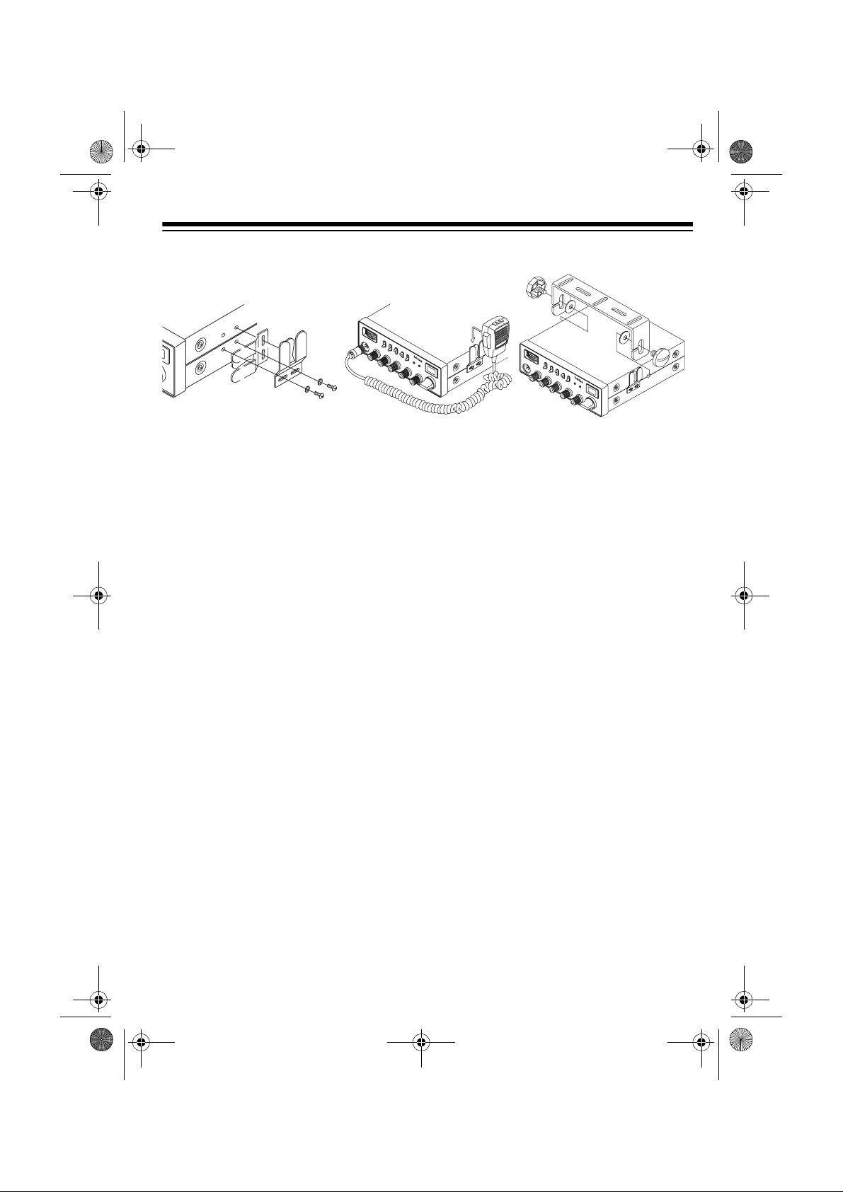
MOUNTING THE
MICROPHONE HOLDER
Using a Philips screwdriver and the supplied screw and washers, attach the
supplied micropho ne holder to the CB's
left or right side, either horizontally or
vertically (depending on how you plan to
use it).
MOUNTING THE TRC-446
The most common mounting location for
this CB is under a vehicle ’s dashboard.
If you use the TRC-446 as a base station, you can place it on a desk, shelf, or
table (See “Using the CB as a Base Station” on Page 8).
When mounting the CB in a vehicle,
choose a location where:
• you can easily reach the CB
• wires and cables are routed away
from the vehicle's pedals or other
moving parts
• all wires and cables can reach their
connection points
• the CB is not directly in front of heating vents
Cautions:
• If you use the TRC-446 in a vehicle,
mount it securely to avoid damage
to the CB or vehicle or injury to anyone in the vehicle during sudden
starts or stops.
• Do not mount the CB where it could
damage or interfere with the proper
operation of any passive restraint
safety device (an air bag or seat
belt).
Follow these steps to mount the CB using the supplied hardware.
1. Select a location that provides
secure mounting.
Caution:
Be careful not to dri ll into
anything behind the mounting surface.
2. Using the slots in the mounting
bracket as a template, mark the
positions for the screw holes.
3. In each marked location, drill a hole
slightly smaller than the supplied
mounting screws.
5
Page 6

21-1574.fm Page 6 Thursday, May 13, 1999 4:03 PM
4. Using a Phillips screwdriver, attach
the mounting bracket to the mounting surface with the supplied large
mounting screw and star lock washers.
5. Attach the CB to the mounting
bracket using the supplied rubber
washers and mounting knobs.
CONNECTING THE
MICROPHONE
1. Align the slot on the top of the
microphone plug with the ridge
ANTENNA
inside the
MIC
jack, then fully inser t
the plug into the jack.
2. Secure the plug by turning the plug's
locking nut clockwise.
3. Slide the microphone onto the
microphone holder.
To disconnect the micr ophone, unsc rew
the locking nut and gently pull out the
microphone plug.
Caution:
Always grasp the connector
body when you are disconnecting the
microphone. Never pull on the microphone cable.
EXT SP
PA SP
POWER
+ 13.8V DC -
PA SP
EXT SP
POWER
-+
13.8V DC
13.8 DC Power Supply
CAT NO.: 21-1574 TRC-446
CUSTOM MANUFACTURED IN THAILAND
A DIVISION OF TANDY CORPORATION
FORT WORTH, TEXAS 76102
0000001
SERIAL NO.:
R
FCC ID: AAO21-1574
FOR RADIOSHACK,
ANTENNA
Base Station Power Setup
6
Page 7

21-1574.fm Page 7 Thursday, May 13, 1999 4:03 PM
INSTALLING AN
ANTENNA
Caution
CB, do not attempt to transmit without
an antenna attached.
Selecting an Antenna
When you decide on an anten na and its
location, consider these points:
Your local RadioS hack sto re sells a va riety of CB antennas fo r both mobile and
base-station use. Choose the one that
best meets your needs.
: To prevent damage to your
• The antenna should be positioned
as high as possible.
• The antenna and the antenna c able
should be routed as far as possible
from any source of electrical noise
such as ignition systems, electric
gauges, and motors.
• Do not run the cable throu gh a vehicle's engine compartment or other
areas that produce extreme heat.
USING VEHICLE
BATTERY POWER
You can power this CB from your vehicle's battery or from standard AC power
with an optional DC power su pply. For information on using AC po we r, see “Usin g
the CB as a Base Station” on Page 8.
Follow these steps to power the CB from
your vehicle's battery.
1. Plug the single-connecto r end of th e
power cord into
on the CB's back panel.
2. Connect the black wire to your vehicle’s negative (–) battery ter minal or
to a metal part of the vehicle's frame
that is not insula ted from the frame
by a plastic part.
POWER 13.8V DC
Connecting an Antenna
Follow the mounting instructions supplied with the antenna you choose.
Route the antenna cable to the CB, then
thread the PL-259 antenna cable plug
ANTENNA
into
Cautions
• Do not run the cable over sharp
edges or moving parts that might
damage it.
• Do not run the ca ble next to power
cables or other CB antenna cables.
on the back of the CB.
:
3. Connect the red wire, with i ts in-line
fuse, to a source of voltage that
turns on and off with the ignition
switch, such as a spare accessory
terminal in your vehicle's fuse box.
This assures you that power to the
CB is turned off when you turn off
the ignition.
4. Connect the orange wire, with its inline fuse, to a source of voltage that
supplies constant positive (+) power
(regardless of the ignition switches
position) or directly to your vehicle's
positive (+) battery terminal. This
enables the radio to “remember” the
last channel you tuned to when you
turn the radio back on.
7
Page 8

21-1574.fm Page 8 Thursday, May 13, 1999 4:03 PM
USING THE CB AS A
BASE STATION
Although this CB is desig ned for mobile
use, you can also use it as a base station. For base-station installation, you
need a regulated 12-volt DC powe r supply, such as Cat. No. 22-504 available at
your local RadioShack store.
Caution:
plies plug into a standard AC outlet to
produce DC power. Before connecting
your CB to a 12-volt DC power suppl y,
read and follow the in str uc ti ons i nc lud ed
with the power supply.
You also need a base station antenna
and coaxial anten na cable and conn ectors. Your local RadioShack store also
carries a wide selection of suitable antennas, cables, and connectors.
Follow these steps to i ns tal l t he CB as a
base station.
1. Mount the base station antenna as
2. Route the antenna cable to the CB,
Most 12-volt DC power sup-
described in its owner's manual.
Warning:
when you install or remove a base
station CB antenna. If the antenna
starts to fall, let it go! It could contact
overhead power lines. If the antenna
touches the power line, contact with
the antenna, mast, cable, or guy
wires can cause electrocution and
death. Call the power company to
remove the antenna. DO NOT
attempt to do so yourself.
then connect the cable to
ANTENNA
Use extreme caution
on the back of the CB.
3. Plug the single connector end of th e
power cord into
on the CB's back panel.
4. Connect the black wire to the DC
power supply's negative (–) terminal.
5. Connect the red wire and orange
wires, with in-line fuses, to the DC
power supply's positive (+) terminal.
Note:
Due to the lack of a constant
12VDC, as in an aut omotiv e inst allat ion,
if you turn off the DC power s upply, the
CB “remembers” the last channel you
tuned for only a few minu tes. Whe n you
turn on the CB and the DC power supply
again, the radio automatically tunes to
Channel 9.
POWER 13.8V DC
CONNECTING OPTIONAL
EXTERNAL SPEAKERS
You can connect an extern al CB or PA
speaker to your CB. The large r, ex ternal
speaker provides greater clarity. A PA
speaker lets you take advantage of the
amplifier and mic to use the CB as a
public-address system.
External CB Speaker
To connect an external CB speaker,
use a speaker rated at 8 -ohms and capable of handling 3–10 watts of power
(such as Cat. No. 21-549). Simply plug
the speaker cable's
EXT SP. Connecting the external speak-
er automatically disconnects the internal speaker.
1
/8-inch plug into
8
Page 9

21-1574.fm Page 9 Thursday, May 13, 1999 4:03 PM
Public Address Speaker
To connect a PA speaker to the CB, use
an 8-ohm speaker capable of handling 5
or more watts of power and equipped
with an
1
/8-inch connector on the cable.
Contact your local RadioShack store
for a selection of suitable speakers.
Plug into
PA SP.
See “Using the Public
Address Function” o n Page 14 for operation instructions.
ADJUSTING THE
STANDING WAVE RATIO
Most antennas are factory adjusted.
However, you can usually imp rove performance by matching the characteristics of your antenna system to the CB's
RF output power using the built-in SWR
meter. The impedan ce of a CB’s out put
compared to the impedance of the antenna and the antenna cab le is typically
slightly mismatched. By adjusting this
impedance ratio to be as c lose to 1:1 as
possible, you maximize th e efficiency of
your system.
points to CAL on the upper SWR
scale.
4. Release the microphone's talk button.
5. Set
S/RF/SWR/CAL to SWR.
6. Press the microphone's talk button
again and note the actual SWR
measurement on the upper SWR
scale. See the char t on Page 10 for
help in inter preting the SWR meter
readings.
The SWR value takes into account the
actual frequency of the RF si gnal transmitted. Therefore, you will get a different
SWR reading from one CB channel to
another. Almost all the CB transmissions usually fall within an acceptable
range. However, for optimu m radio performance, we rec ommend that you fine
tune the antenna's sy stem b ased on th e
channel you use most. If you have no
particular channel preference, set your
antenna's SWR for maximum performance on Channel 19.
After you have properly installed the an tenna and routed its c able, follow these
steps to adjust the standing wave ratio
Note:
The SWR on some mobile and
base-station antennas cannot be
changed.
1. Turn on the CB by turni ng
UME
clockwise until it clicks.
2. Set
S/RF/SWR/CAL to CAL.
OFF/VOL-
3. Hold down the microphone's talk
button and adjust
SWR CAL so the
SWR/RF signal meter's needle
9
Page 10

21-1574.fm Page 10 Thursday, May 13, 1999 4:03 PM
STANDING WAVE RATIO GUIDELINES
The ideal standing wave ratio (SWR) is 1:1, or a meter reading of 1 on the SWR
meter's top scale. This reading, however, can only be obtained under laboratory conditions. A SWR ratio of 1.5:1 to 2:1 is excellent for most mobile CB antenna applications. This chart helps you interpret the different readings you might see.
Standing Wave Ratio Performance
Ratio Rating Evaluation
1:1 – 1.5:1 Superior Perfect match between the an-
tenna/cable and the RF output of
the CB.
1.5:1 – 2:1 Excellent The antenna/cable system is an
outstanding match to the transmitter’s RF output. Ideal for most
CB installations.
2:1 – 3:1 Good The antenna/cable system will
perform to specification under
most normal conditions.
Higher than
3.1:1
Inefficient Indicates a need to inspect the
system, the mounting of the
antenna and all pertinent hardware.
Prolonged exposur e to sal t spray, humidity, weat her- ind uc ed cor r osion, or vehicle vibration can cause antenna performance to degrade with a subsequent rise in the
SWR. Anytime you noti ce that the SWR reading is great er than 3:1 , ch eck the condition of the antenna, the antenna cable and all antenna connectors and hardware.
10
Page 11

21-1574.fm Page 11 Thursday, May 13, 1999 4:03 PM
A QUICK LOOK AT THE CONTROLS
SWR Meter
Channel 9-NORChannel 19 Switch
RF Meter
RF Meter/SWR/
Calibrate Switch
CB/Weather Alert/Public Address Switch
Noise Blanking On/Off
Switch
Audio Clarity
Enhancer On/Off
Switch
Transmit/Receive
Indicator
Channel Display
Weather Alert
Indicator
Hand-Held MIC with
Channel Up/Down
Control
Volume /
Power Switch
Squelch
Control
Standing Wave Ratio
Calibration Control
RF Gain
Control
Rotary Channel
Tuning Dial
NOAA
Weather
Channel
Selector
11
Page 12

21-1574.fm Page 12 Thursday, May 13, 1999 4:03 PM
OPERATION
Before you start using your CB, you
should know how to use it effectively
and courteously. “CB Operation Tips” on
Page 15 contains information that will
help you get more enjoyment from using
your CB.
TURNING ON THE CB AND
RECEIVING
TRANSMISSIONS
1. Turn SQUELCH fully counterclockwise.
2. Set
3. To turn on the CB, turn
4. Turn
5. Adjust
CH-9/NOR/CH-19 to NOR, S/RF/
SWR/CAL
receive), and
clockwise until it clicks and you hear
a hissing sound. TX/RX lights, the
CB displays the last-tuned channel
number, and the SWR/RF/Signal
Meter lights.
hissing sound stops.
Note:
partial or very weak transmissions,
continue to turn
to decrease the CB's sensitivity to
these signals. Tur n
terclockwise if you want to listen to a
weak or distant station.
able listening level.
to S/RF (send and
CB/WX/PA to CB.
OFF/VO LUM E
SQUELCH clockwise until the
If the CB picks up unwanted,
SQUELCH clockwi se
SQUELCH coun-
OFF/VOLUME to a comfort-
6. To manually tune c hannels, turn th e
tuning control beneath the display to
select a channel. The selected
channel number appears, and the
SWR/RF/Signal Meter shows the
signal strength.
To quickly tune to Channel 9 or 19,
set
CH-9/NOR/CH-19 to CH-9 or CH-
19
. 9 or 19 flashes.
Important:
communications priority on Channels 9 and 19. Your CB provides for
fast selection of Channel 9 and 19
for that reason.
Notes:
• Selecting either C hannel 9 or 19
overrides the manual channel
selection control.
• All channels, with the exception of
Channels 9 and 19, by agreement, are available for general
communications. Channels 9 and
19 are reserved for motorist
assistance and for reporting
emergency situations, hazardous
road conditions, and the like.
7. If necessary, turn
to boost the strength of a signal.
8. If you hear low-level popping-type
noise, set
the noise blanking circuit.
9. To improve communication quality,
set
ACE/OFF to ACE. This enables
the ACE circuit.
Always give emergency
RF GAIN clockwise
NB/OFF to NB
to turn on
12
10. To turn off the TRC-446, turn
VOL UM E
hear it click.
counterclockwise until you
OFF/
Page 13

21-1574.fm Page 13 Thursday, May 13, 1999 4:03 PM
Changing Channels Using the
Controls on the Microphone
To tune to the next higher or lower channel, press
UP or DOWN on the micro-
phone.
To quickly chang e channels i n either di-
rection, hold down
UP or DOWN until you
reach the desired channel.
To prevent accidentally changing the
channel with
Press
LOCK again to restore the UP or
DOWN operation.
UP or DOWN, press LOCK.
TRANSMITTING
Note
: We recommend you tr y receiving
transmissions before you transmit.
1. Follow Steps 1–9 under “Tur ning On
the CB and Receiving Transmissions” on Page 12.
2. Hold down the microphone's talk
button and speak into the microphone in a normal voice from about
2–3 inches away. TX/RX tur ns red,
and the SWR/RF/signal meter indicates the strength of your transmission.
4. To turn off the TRC-446, turn
VOL UM E
counterclockwise until you
OFF/
hear it click.
LISTENING TO
WEATHER BR OADCASTS
The TRC-446 can receive seven preprogrammed weather channels which
have been allocated by the Federal
Communications Commission (FCC) for
use by the National Ocean ographic and
Atmospheric Administration (NOAA).
NOAA broadcasts your local forecast
and regional weather information on one
or more of these channels in your area.
Your TRC-446 receives these weather
service frequencies:
Frequency
(MHz)
162.400 WX2
162.425 WX4
162.450 WX5
162.475 WX3
162.500 WX6
162.525 WX7
162.550 WX1
Channel
Note
: Do not speak too lou dly wh en
transmitting. It does not make your
signal any stronger, and might distort your transmission.
3. When you finish transmitting,
release the microphon e talk button.
TX/RX turns green. The TRC-446
can now receive transmissions.
13
Page 14

21-1574.fm Page 14 Thursday, May 13, 1999 4:03 PM
To listen to one of the seven available
weather channels, set
then rotate
WEATHER to choose a chan-
CB/WX/PA to WX,
nel for your listening a rea. The channel
display and the SWR tur n off. Readjust
OFF/VOLUME if necessary.
Note:
When the CB radio is s et t o
PA, and you enter a NOAA broadcast ar-
CB or
ea, the state of the WX/ALERT indicates
three possible situations:
OFF — No weather signal on the
selected weather channel. Check
another channel.
GREEN — Normal weather signal.
No emergecy broadcast.
ORANGE — Weather alert broadcast on the selected channel. Turn
to
WX to listen to information or
power off then on to clear the alert.
Weather Alert
In the event of severe weather conditions, the National Weather Service
broadcasts a spec ial 105 0 Hz tone . The
TRC-446 sounds this tone if it i s turned
on and
The tone does not sound if the radio is
set to
signal tone, WX/ALERT lights orange
regardless of the position of
CB/WX/PA is set to CB or WX.
PA. When the radio r eceives this
CB/WX/PA.
However, WX/ALERT turns off if you
turn to
WX or move out of the range of
that NOAA chann el. To turn off the indicator you can also tu rn power off, then
on.
The orange indicator means switch to
WX
to hear special severe weather in-
formation and warnings.
USING THE PUBLIC
ADDRESS FUNCTION
1. Connect a PA speaker to the TRC446 (see “Connecting Optional
External Speakers” on Page 8).
2. Turn
3. Set
4. Hold down the microphone talk but-
5. Adjust
OFF/VOLUME fully counter-
clockwise.
CB/WX/PA to PA. The meter and
TX/RX turn off.
ton and speak into the microphone
in a normal voice. Be sure the
microphone is as far from the PA
speaker as possible to reduce the
possibility of audio feedback or
howl.
OFF/VOLUME as needed to
adjust the PA's volume.
NOAA transmits this tone for 5 to 10
seconds. If the TRC-446 is set to
PA, the orange li ght rem ains o n even af -
CB or
ter transmission ceases. You do not
have to be present when the signal is received to be aware of an alert.
14
Page 15

21-1574.fm Page 15 Thursday, May 13, 1999 4:03 PM
CB OPERATION TIPS
Like most activities, CB radio users have
customs and courtesies. The following
tips will help you get the most enjoyment
out of your CB.
TYPICAL USES
FOR A CB RADIO
Business Uses
• Truck dri vers and deliver y pers onnel
can learn r oad and t raffic con ditions
and get assistance in loc ating destinations. A CB is also good company
on these “long hauls.”
• Used by construction crews, a CB
quickly pays for itself when you are
calling for additional materials or
coordinating the activities of different work crews.
• For security officers, a CB is more
than a convenience — it is a must
for both safety and efficiency.
• Contact frie nds or neighbo rs — find
out “what's happening” or plan a
get-together.
• Ever have car trouble or run out of
gas on the highway? With your CB
you can have peace of mind knowing you can call for assistance.
• Camping, fishing, and other sports
are more fun with a CB. Keep in
touch with a buddy or find out
“what's cooking” back at camp.
CB Courtesy
• Wait for a pause in someone else's
transmission before you ask for a
break.
• If you do not receive an answer to
your call after a second attempt,
sign off and wait several minutes
before trying again.
• Do not hold down the microphone
talk button, called “dead keying”,
when you are talking.
Personal Uses
• Keep in touch with home while driving to work, to the store, or to a
social activity. Let your family know
you are tied up in traffic or that you
will stop by the store on the way
home.
• If you are a two-or-more car family,
CBs are gre at for inter-ca r c omm unications while family members are
going places.
• Assist callers with directions, information about road conditions, and
any other reasonable requests.
15
Page 16

21-1574.fm Page 16 Thursday, May 13, 1999 4:03 PM
USING COMMON 10-CODES
Citizen's band operators have largely
adopted the followin g 10 -cod es for s tan dard questions and answers. These
codes permit faster and more precise
communication in noisy areas. This table lists codes ado pted by the As sociated Public-Safety Communications
Officers (APCO).
Code Meaning
10-1 Your signal is bad.
10-2 Your signal is good.
10-3 Stop transmitting.
10-4 Message received and under-
stood.
10-5 Relay information to ______.
10-6 I am busy or are you busy?
10-7 Out of service.
10-8 In service.
10-9 Repeat last message.
10-10 Negative (NO).
10-11 ____________in service.
10-12 Stand by.
Code Meaning
10-21 Call______by telephone.
10-22 Cancel last message.
10-23 Arrived at the scene.
10-24 Assignment complete.
10-25 Meet______________.
10-26 Estimated time of arrival
is___
10-30 Use caution.
10-31 Pick up.
10-33 Emergency traffic. Clear the
channel.
10-34 What time is it?
10-41 Switch to Channel –
10-62 Cannot understand.
Note:
Although this table lists the 10codes’ meanings in the form of a sta tement, they can also be phrased as
questions (10-6: A re you busy?, 10-20:
What is your location?).
10-13 Report road/weather
conditions.
10-14 Information.
10-15 Message delivered.
10-16 Reply to message.
10-17 En route.
10-18 Urgent
10-19 Contact_______
10-20 What’s your location?
16
Page 17

21-1574.fm Page 17 Thursday, May 13, 1999 4:03 PM
MAXIMUM RANGE
The maximum range and q uality of CB
transmissions vary depending on the following typical conditions:
• The type and quality of antenna
used.
• The height of the antenna's mo unting location — the higher the
antenna, the greater the signal's
range
• The surrounding terrain — mountains and tall buildings limit the
range.
• Weather conditions.
• The number of nearby CBs operating on the same channel.
REDUCING NOISE
The audio clarity enh ancer (ACE) circuit
uses compander (compressor and expander) technology to im prove communication quality. The circuit maintains
the dynamic range while increasing the
signal-to-noise r atio as the gain is automatically contro lled according to the input signal level. This results in a
reduction in wide band noise.
If you suspect engine noise as a source,
turn off the engine and operate the CB
with the ignition set to ACC. If most or all
of the noise stops, th e problem is in vehicle's igni tion or electrical system.
The following few hints can help you r educe or eliminate such noise.
• Replace old ignitio n wires with new,
high-voltage, noise-suppression
wires.
• Install noise suppressors on your
spark plugs, or install new spark
plugs that have built-in suppressors.
• Be sure that the black wire ground
connection is securely attached to
either your vehicle’s battery's negative (GND) terminal or to a good
electrical chassis ground.
If problems persi st, check your alternator or generator, voltage regulator, and
any stand-alone gauges. Noise from
these sources can be reduced or eliminated using bypass capacitors at various output voltage points.
Your local RadioShac k store ha s a wide
selection of n oise-s uppress ion acce ssories.
The noise blanking (NB) circuit helps
keep background noise to a minimum.
However, strong sources of electrical
noise, generated by spark plugs or the
ignition of your car, or another radio,
might be more than the circ uit can c ompensate for.
17
Page 18

21-1574.fm Page 18 Thursday, May 13, 1999 4:03 PM
TROUBLESHOOTING
If your CB is not working as it should, foll ow the suggest ions below to s ee if you can
eliminate the problem. If the proble m persists , take the CB to your local RadioSha ck
store for assistance.
Symptom Check That:
Reception difficulties OFF/VOLUME is turned on.
CB/WX/PA is set to
OFF/VOLUME
RF GAIN is set to the correct level.
CB
is at a sufficient listening level.
The microphone is securely plugged into
The antenna cable is securely plugged into
on the rear of the radio and attached securely to the
antenna at the other end.
Transmission difficulties The CB is turned on.
OFF/VOLUME
is at a sufficient listening level.
The microphone is securely plugged into
All connectors (microphone, antenna, speakers) are
tight and secure.
When transmitting, you are fully pressing the micro-
phone talk button.
The antenna is properly mounted and not obstructed or
grounded.
No channel selection or
only Channel 9 or 19
can be selected.
CB/WX/PA is set to
CH9/NOR/CH-19 is set to
CB
NOR
MIC
.
ANTENNA
MIC
.
No operation at all. The power supply and in-line fuse are functioning
(“Replacing the Fuses” on Page 20)
18
Page 19

21-1574.fm Page 19 Thursday, May 13, 1999 4:03 PM
CARE AND MAINTENANCE
Your RadioShack T RC-446 Deluxe 40-Channel M obi le CB i s an exam pl e o f s up erior design and craftsmanship. The following suggestions will help you care for
your TRC-446 so you can enjoy it for years.
Keep the CB dry. If it gets wet, wip e it dry immediately. Liquid s might
contain minerals that can corrode the electronic circuits.
Use and store the CB only in nor mal temper ature envir onments. Temperature extremes can shorten the life of electronic devices, and distort
or melt plastic parts.
Keep the CB away from dust and dirt, which can cause premature
wear of parts.
Handle the CB gently and carefully. Dropping it can damage circuit
boards and cases and can cause the CB to work improperly.
Wipe the CB with a damp cloth occasionally to keep it looking new. Do
not use harsh chemicals, cleaning solvents, or strong detergents to
clean the CB.
Modifying or tampering with the CB’s internal components can cause a malfunction
and might invali date its warranty and void your FCC authorization to operate it. If
your CB is not performi ng as it should, take it to you r local RadioShack st ore for
assistance.
19
Page 20

21-1574.fm Page 20 Thursday, May 13, 1999 4:03 PM
REPLACING THE FUSES
The TRC-446's 2-amp fuses help protect your CB from power surges and
short circuits.
•
If the red wire's fuse is blown
replace it with a 2-amp, fast-acting
glass fuse, such as Cat. No. 270-
1007.
•
If the orange wire's fuse is blown
replace it with a 1-amp, fast-acting
glass fuse, such as Cat. No. 270-
1005.
Follow these steps to replace each fuse.
1. Make sure the power source and CB
are both off.
,
,
2. To open the fuse holder, push the
fuse holder ends toget her, then turn
either end counterclockwise and
release it.
3. If the fuse is blown, replace it.
Caution:
ings other than those specified here.
Doing so might d amage your TRC-
446.
4. Close the fuse holder by pushing the
fuse holder ends toget her, then turn
either end clockwise.
Do not use a fuse with rat-
20
Page 21

21-1574.fm Page 21 Thursday, May 13, 1999 4:03 PM
SPECIFICATIONS
GENERAL
Channels ................................................................................................. 40 Channels
Frequency Range ........................................................... 26.965 MHz to 27.405 MHz
Power Requirements ........................ .. 13.8V DC (12–16 Volts DC, Negative Ground)
Dimensions (HWD) ................................................................. 2
Weight ................................................................................................. 3.1 lbs (1.4 kg)
RECEIVER
Sensitivity ................. ............. ............. ............. ...... 0.5 µV or better for 10 dB (S+N)/N
Adjacent Channel Rejection ......................................................... 50 dB (at 10 kHz)
Audio Output ............................................................................ 4.5 Watts (Maximum)
1
/4 × 71/4 × 77/8 Inches
(57 × 184 × 200 mm)
Frequency Response ............................................................................ 450–2500 Hz
Intermediate Frequency ............................................................... 1st IF: 10.695 MHz
2nd IF: 455 KHz
Cross Modulation ............................................................................................... 50 dB
Squelch ..................................................................... Adjustable from 0.5 µV to 1 mV
TRANSMITTER
Output Power ...................................................................... 4 Watts (FCC Maximum)
Type of Modulation .............................. AM Double-Sideband, Full Carrier Modulation
Modulation Capability ........................................................................................ ±90%
Spurious Emission ......................................................................... Less than –70 dB
Frequency Tolerance ...................................................................................... ±200 Hz
Antenna Impedance ....................................................................................... 50 Ohm
Current Drain ....................................... (13.8-volt supply) 1 Amp with No Modulation
1.6 Amps with 80% Modulation
21
Page 22

21-1574.fm Page 22 Thursday, May 13, 1999 4:03 PM
PUBLIC ADDRESS
Output Power ............................................................................ 4.2 Watts (Maximum)
Current Drain (at maximum power) .............................................................. 1.2 Amps
WEATHER RADIO
Frequency Coverage (MHz) ........................................................................... 162.400
162.425
162.450
162.475
162.500
162.525
162.550
Specifications are typical; individual units might vary. Specifications are subject to
change and improvement without notice.
22
Page 23

21-1574.fm Page 23 Thursday, May 13, 1999 4:03 PM
NOTES
23
Page 24

21-1574.fm Page 24 Thursday, May 13, 1999 4:03 PM
Limited Ninety-Day Warranty
This product is warranted by RadioShack agai nst manufactur ing defects in mater ial and workman ship under norma l use for ninety (90) day s from the date of purchas e from RadioS hack company owned stores and authorized RadioShack franchisees and dealers. EXCEPT AS PROVIDED
HEREIN, RadioShack MAKES NO EXPRESS WARRANTIES AND ANY IMPLIED WARRANTIES,
INCLUDING THOSE OF MERCHANTABILITY AND FITNESS FOR A PARTICULAR PURPOSE,
ARE LIMITED IN DURATION TO THE DURATION OF THE WRITTEN L IMITED WARRANTIES
CONTAINED HEREIN. EXCEPT AS PROVIDED HEREIN, RadioShack SHALL HAVE NO LIABILITY OR RESPONSIBILITY TO CUSTOMER OR ANY OTHER PERSON OR ENTITY WITH RESPECT TO ANY LIABILITY, LOSS OR DAMAGE CAUSED DIRECTLY OR INDIRECTLY BY USE
OR PERFORMANCE OF THE PRODUCT OR ARISING OUT OF ANY BREACH OF THIS WARRANTY, INCLUDING, BUT NOT LIMITED TO, ANY DAMAGES RESULTING FROM INCONVENIENCE, LOSS OF TIME, DATA, PROPERTY, REVENUE, OR PROFIT OR ANY INDIRECT,
SPECIAL, INCIDENTAL , OR CONSEQUENTI AL DAMAGES, EVE N IF Radio Shack HAS BEEN ADVISED OF THE POSSIBILITY OF SUCH DAMAGES.
Some states do not allow the limitations on how long an implied warranty lasts or the exclusion of incidental or consequential damages, so the above limitations or exclusions may not apply to you.
In the event of a p roduct defect dur ing the warranty p eriod, take the pr oduct and the Rad ioShack
sales receipt as proof of purchase date to any RadioShack store. RadioShack will, at its option, unless otherwise pro vided by law: (a) correct the defe ct b y p rod uct rep air wi tho ut char ge for pa rts and
labor; (b) replace the product with o ne of the same or sim ilar design; or (c) refund the purchas e
price. All repla ced parts and prod ucts, and products on which a re fund is ma de, becom e the pr operty of RadioShack . New or recon ditioned parts an d products may b e used in the p erformance of
warranty service. Repaired or repl aced parts and products are wa rranted for the remainder of th e
original warranty period. You will be charged for repair or replacement of the product made after the
expiration of the warranty period.
This warranty does not cover: (a) damage or failure caused by or attributable to acts of God, abuse,
accident, misuse, i mpro per o r abn or mal usa ge , fa ilur e t o fol low i nst ruct ions, improper installati on o r
maintenance, altera tion, lightning or oth er incidence of excess voltage or current ; (b) any repairs
other than those provide d by a RadioShack Authorize d Service Facility; (c) consumab les such as
fuses or batteries; (d) cosme tic dam age; (e ) trans portatio n, shi pping or insuranc e costs; or ( f) costs
of product removal, installation, set-up service adjustment or reinstallation.
This warranty gives you specific lega l rights, and you may also have other rig hts which vary from
state to state.
RadioShack Customer Relations, 200 Taylor Street, 6th Floor, Fort Worth, TX 76102
We Service What We Sell
04/99
RadioShack
A Division of Tandy Corporation
Fort Worth, Texas 76102
05A99 Printed in Thailand
937485
 Loading...