

Page 1

43-109 6.fm Page 1 Tuesday, August 17, 1999 3:47 PM
900-MHz Digital Spread Spectrum
Cat. No. 43-1096
OWNER’S MANUAL
Please read before using this equipment.
ET-92 6
Cordless Phone
Page 2

gy
y
y
g
g
g
g
y
g
y
43-109 6.fm Page 2 Tuesday, August 17, 1999 3:47 PM
FEATURES
Your RadioShack ET-926 900-MHz
Digital Spread Spectrum Cordless
Phone uses the most advanced cordless telephone technology to give you
superior audio quality and extended
range.
Its features include:
Spread Spectrum Technolo
—
spreads signals out over several frequencies rather than locking onto just
one.
900-MHz Operation
— provides less
interference, clearer sound, and longer
range than many other cordless
phones (over twice the range of 46/49MHz cordless phones).
20 Channels
— automatically selects
a clear channel when you make or answer a call.
Securit
Access-Protection Code
—
automatically prevents other cordless
phone users from using your phone
line while the handset is off the base.
Redial
— lets you quickly redial the
last number dialed.
20-Number Memor
Dialin
— lets
you store up to 20 numbers in memory
for easy dialing.
— lets you send a paging signal
Pa
e
from the base to the hand set to page
someone or loca te the handset if you
misplace it.
— sends an electronic switch-
Flash
hook signal for use with special phone
services, such as Call Waiting.
Volume Control
— lets you adjust the
volume you hear through the handset.
Pro
rammable Ringer
— lets you se-
lect from eight tone/volume settings.
Tone/Pul se Dialin
— you can use
this phone with either type of service.
Quic k Talk
— lets you answer a call
by just lifting the handset from the
base.
An
Key Answer
— lets you press
any key to answer a call when the
handset is away from the base.
Hearin
-Aid Compatibilit
— lets
you use your phone with he aring aids
that have a T (telephone) switch.
This telephone has been tested and
found to comply with all applicable UL
and FCC standards.
© 1997 Tandy Corporation.
RadioShack is a registered trademark used by Tandy Corporation.
All Rights Reserv ed .
2
Page 3
43-109 6.fm Page 3 Tuesday, August 17, 1999 3:47 PM
Important Note: Cordless phones
such as this one require AC power to
operate. When the AC power is off,
you cannot dial out or receive incoming
calls using your ET-926. To be safe,
you should also have a phone that
does not need AC power to operate
(not a cordless ph one) so you can still
make and receive calls if there is an
AC power failure.
We recommend you record your
phone’s serial number here. The number is on the bottom of the base.
Serial Number __________________
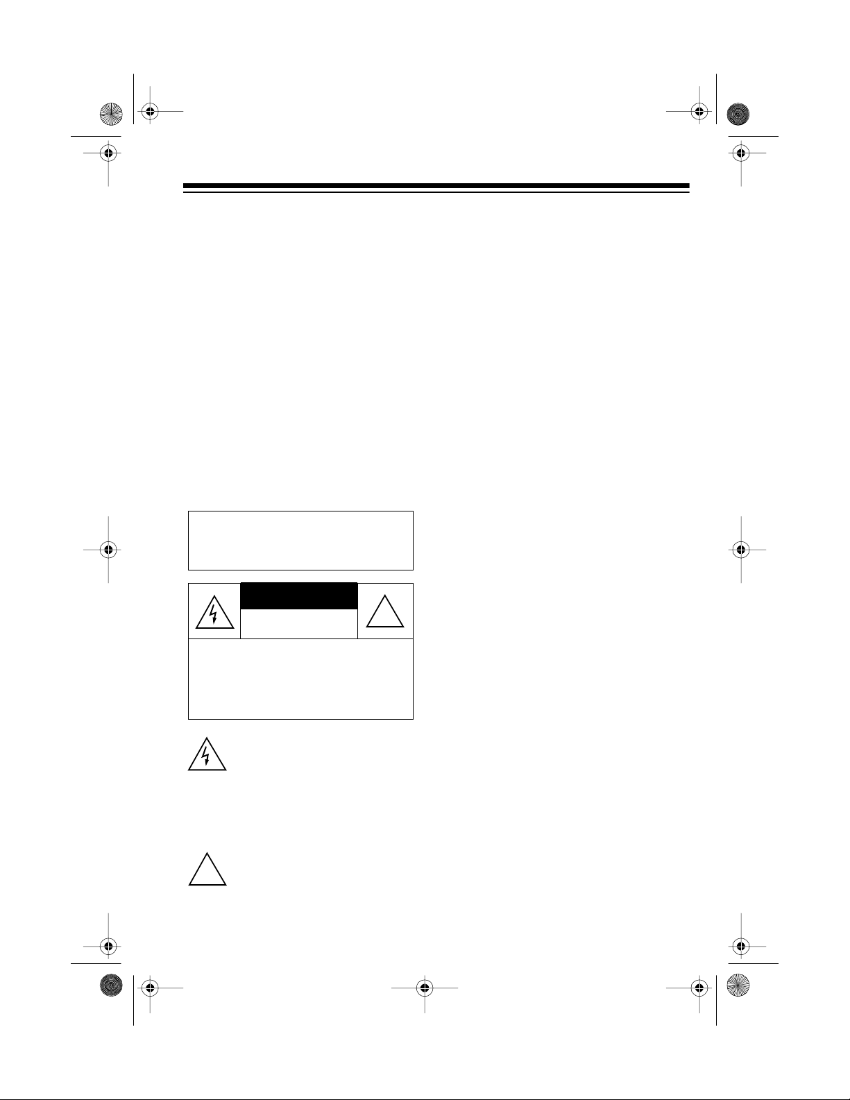
Warning: To reduce the risk of fire
or shock hazard, do not expose
this product to rain or moisture.
CAUTION
RISK OF ELECTRIC SHOCK.
DO NOT OPEN.
CAUTION: TO REDUCE THE RISK OF
ELECTRIC SHOCK, DO NOT REMOVE
COVER OR BACK. NO US ER-SERVICEABLE PARTS INSIDE. REFER SERVICING TO QUALIFIED PERSONNEL.
This sym bol is in te nd ed to a le rt yo u
to the pr e s en ce of uninsulated da ngerous voltage within the product’s
enclos u re t h at m ig ht b e of s ufficient
magnitude to constitute a risk of
electric shock. Do not open the
product’s case.
!
READ THIS BEFORE
INSTALLATION
Each device that you connect to the
phone line draws power from the
phone line. We refer to this power draw
as the device’s
number
, or REN. The REN is on the
ringer equivalence
bottom of the base.
If you are using more than one phone
or other device on the line, add up all
the RENs. If the total is more than five,
your phones might not ring. In rural areas, a total REN of three might impair
ringer operation. If ringer operation is
impaired, remove a device from the
line.
FCC STATEMENT
This telephone complies with Part 68
FCC Rules
of
quest, provide the FCC Registration
Number and the REN to your phone
company. These numbers are on the
bottom of the base.
Note: You must not connect your
phone to any of the following:
• coin-operated syst e ms
• party-line systems
• most electronic key phone systems
. You must, upon re-
This symbol is intended to inform
you that important operating and
!
maintenance instructions are included in th e l itera ture a ccomp an ying this product.
3
Page 4

g
43-109 6.fm Page 4 Tuesday, August 17, 1999 3:47 PM
CONTENTS
Installation ............................................................................................................ 5
Selecting a Location ........................................................................................ 5
Placing the Base on a Desk Top ............................................................... 5
Mounting the Base on a Wall Plate ........................................................... 6
Mounting the Base Directly on th e Wall .................................................... 8
Connecting and Charging the Battery Pack .................................................. 10
Setting the Dialing Mode ............................................................................... 11
Setting the Ringer Tone/ Volume .................................................................... 12
Using the Belt Clip ......................................................................................... 12
Operation ............................................................................................................ 13
Making and Receiving Calls .......................................................................... 13
Setting the Handset Volume ..................................................... ................... .. 13
Using Redial .................................................................................................. 13
Using Flash .................................................................................................... 14
Using Tone Servi ces on a Pulse Line ............................................................ 14
Paging ........................................................................................................... 14
Memory Dialing .............................................................................................. 15
Storing a Number in Memory .................................................................. 15
Entering a Pause .................................................................................... 16
Dialing a M emory Number ...................................................................... 16
Chain-Dialing Service Numbers .............................................................. 16
Testing Stored Emergency Numbers ...................................................... 17
Troubleshootin
Care and Maintenance ....................................................................................... 20
Replacing the Battery Pack ........................................................................... 21
The FCC Wants You to Know ........................................................................ 22
Lightning ........................................................................................................ 22
4
................................................................................................. 18
Page 5
43-109 6.fm Page 5 Tuesday, August 17, 1999 3:47 PM
INSTALLATION
SELECTING A
LOCATION
You can place the ET-926’s base on a
desk top or table, or mount it on a wall.
Select a location that is:
• near an AC outlet
• near a telephone line jack
• out of the way of normal activities
• away from electrical machinery,
electrical appliances, metal walls
or filing cabinets, wireless intercoms, alarms, and room monitors
• away from other cordless phones
The base’s location affects the handset’s range. If you have a choice of
several locations, try each to see
which provides the best performance.
Caution:
AC adapter was designed specifically
for your ET-926. Use only the supplied
adapter.
The supplied RadioShack
• The USOC number o f the jack to
be installed is RJ11C (RJ11W if
you want to mount it on a wall
plate).
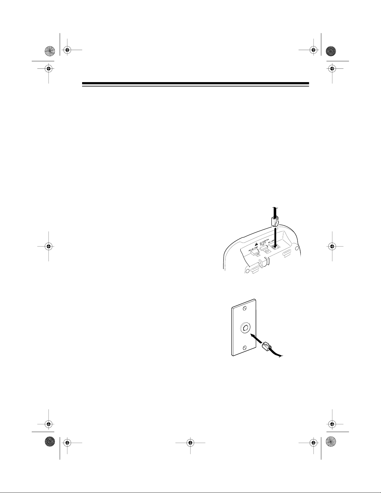
Placing the Base on a
Desk Top
Follow these steps when you place the
base on a desk, shelf, or table.
1. Plug one en d of the supp lied long
modular cord into the
jack on the back of the base.
2. Plug the modular cord’s other end
into a modular phone line jack.
TEL LINE
Notes:
• Your telephone connects directly
to a modular telephone line jack. If
your phone line jack is not a modular jack, you can update the wiring yourself, using jacks and
adapters available at your local
RadioShack store. Or, you can let
the phone company update the
wiring for you.
5
Page 6
43-109 6.fm Page 6 Tuesday, August 17, 1999 3:47 PM
3. Insert the supplied AC adapter’s
barrel plug into the
DC IN 9V
jack
on the back of the base.
4. Route the adapt er’s cord through
the strain relief slot on the base.
Strain Relief
Slot
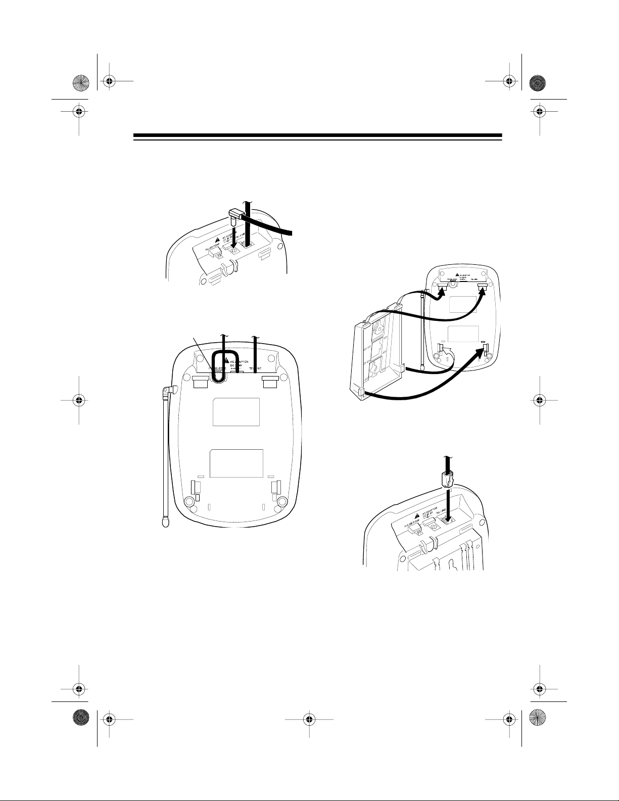
Mounting the Base on a
Wall Plate
1. Insert the two catches at the top of
the bracket into the upp er slots on
the bottom of the base. Then
press the two latches on the sides
of the bracket into the lower slots.
2. Plug one end of the supplied short
modular cord into the
jack on the back of the base.
TEL LINE
5. Plug the adapter into a standard
AC outlet.
6. Lift the base’s antenna to a vertical position.
6
Page 7

AC ADAPTOR
DC IN 9V
PULSE-TONE
TEL LINE
43-109 6.fm Page 7 Tuesday, August 17, 1999 3:47 PM
3. Route the modular cord through
the wide right groove on the bottom of the bracket.
AC ADAPTOR
DC IN 9V
PULSE-TONE
TEL LINE
4. Insert the supplied AC adapter’s
barrel plug into the
DC IN 9V
jack
on the back of the base.
5. Route the adapter ’s cord through
the narrow groove on the bottom
of the bracket.
6. Plug the short modular cord into
the wall plate jack, press the
excess cord into the slot in the
center of the bracket, then align
the bracket’s keyhole slots with
the wall plate studs and slide the
base downward to secure it.
AC ADAPTOR
DC IN 9V
PULSE-TONE
TEL LINE
7. Plug the adapter into a standard
AC outlet.
8. Lift the base’s antenna to a vertical position.
7
Page 8
AC ADAPTOR
DC IN 9V
PULSE-TONE
TEL LINE
43-109 6.fm Page 8 Tuesday, August 17, 1999 3:47 PM
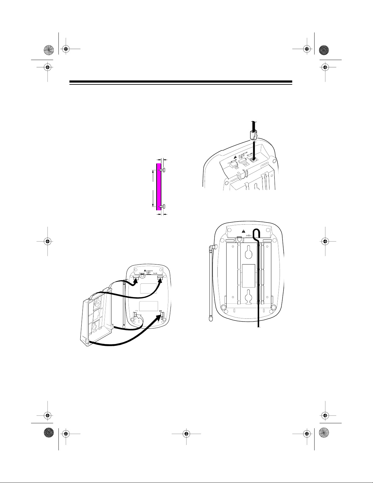
Mounting the Base Directly
on the Wall
For this mounting method, you need
two flat-head wood screws (not supplied) with heads that fit into the keyhole slots on the bottom of the base.
1. Drill two holes 3
5
/
16
inches apart. Then
thread a screw into
each hole, letting the
heads extend about
3
/16 inch from the
wall.
2. Insert the two catches at the top of
the bracket into the upper slots on
the bottom of the base. Then
press the two latches on the s id es
of the bracket into the lower slots.
35/
3
/
16
16
3. Plug one en d of the supp lied long
modular cord into the
TEL LINE
jack on the back of the base.
4. Route the modular cord through
the wide right groove on the bot tom of the bracket.
8
Page 9

AC ADAPTOR
DC IN 9V
PULSE-TONE
TEL LINE
43-109 6.fm Page 9 Tuesday, August 17, 1999 3:47 PM
5. Insert the supplied AC adapter’s
barrel plug into the
DC IN 9V
jack
on the back of the base.
6. Route the adapt er’s cord through
the narrow groove on the bottom
of the bracket.
AC ADAPTOR
DC IN 9V
PULSE-TONE
TEL LINE
7. Align the keyhole slots with the
mounting screws and slide the
base downward to secure it.
8. Plug the modular cord into a modular phone line jack.
9. Plug the adapter into a standard
AC outlet.
10. Lift the base’s antenna to a vertical position.
9
Page 10

43-109 6.fm Page 10 Tuesday, August 17, 1999 3:47 PM
CONNECTING AND
CHARGING THE
BATTERY PACK
The ET-926 comes with a rechargeable nickel-cadmium battery pack in
the handset. Before using your phone,
you must connect the battery pack,
then charge it for about 14 hours.
1. Slide the cover in the direction of
the arrow to remove it.
2. Unfasten the plastic retainer strap
and lift the battery pack out of the
compartment. Plug the battery
pack’s connector into the socket in
the compartment. The connector
fits only one way.
3. Replace the battery pack inside
the compartment and refasten the
retainer strap.
When the handset beeps and the Talk/
Batt Low indicator on the handset
flashes, recharge the battery pack.
Notes:
• If the In Use/Charge indicator
does not light when you place the
handset on the base, be sure the
battery pack and AC adapter are
correctly and securely connected.
Also, check the charging contacts
on the handset and the base. If
the contacts are dirty or tarnished,
clean them with a pencil eraser.
4. Replace the cover.
To charge the battery pack, place the
handset upright on the base if you
placed the ET-926 on a desk top, or
hang the handset on the h older if you
mounted it on a wall. The In Use/
Charge indicator on the base lights.
10
Page 11

43-109 6.fm Page 11 Tuesday, August 17, 1999 3:47 PM
• When you first use the phone after
charging or recharging the battery
pack, the phone might not work
and you might hear an error to ne.
If this happens, return the handset
to the base for a few seconds.
• About once a month, fully discharge the battery pack by keeping the handset off the base until
the Talk/Batt Low indicator
flashes. Otherwise, the battery
pack loses its ability to fully recharge.
Note: The security code is not l o st
even if the battery pack is completely discharged.
• If the Talk/Batt Low indicator does
not light and the phone does not
work, recharge the battery pack.
(The battery power might be too
low to light the indicator.)
• If the battery pack becomes weak
during a call, you hear a beep every 16 seconds and the Talk/Batt
Low indicator flashes. Recharge
the battery pack.
• The supplied battery p ack should
last for about a year. When the
battery pack loses its ability to
fully recharge, order a replacement battery pack from your local
RadioShack store (see “Replacing
the Battery Pack” on Page 21).
SETTING THE DIALING
MODE
PULSE-TONE
Set
base for the type of service you have.
If you are not sure which type you
have, do this test.
1. Set
PULSE-TONE
2. Lift the handset, press
listen for a dial tone.
3. Press any number other than 0.
Note: If your phone system
requires that you dial an access
code (9, for example) before you
dial an outside number, do not
press the access code either.
If the dial tone stops, you have
touch-tone service. Leave
TONE
set to
If the dial tone continues, you
have pulse service. Set
TONE
to
on the back of the
TONE
to
TONE
.
PULSE
.
.
Talk
PULSE-
PULSE-
, and
11
Page 12

43-109 6.fm Page 12 Tuesday, August 17, 1999 3:47 PM
SETTING THE RINGER
TONE/VOLUME
You can select one of eight different
ringer tone/volume settings — four
tones, with high/low volume for each
— while the phone is not in use.
To hear and change the ringer volume
setting,
press
To change the tone,
enter the ringer tone number (1–4) using the number keys.
Volume
s or t.
press
Flash
then
USING THE BELT CLIP
You can carry around the hands et on
your belt. Carefully remove the lid on
top of the handset a nd atta ch the supplied belt clip.
Lever
Belt
Clip
To remove the belt clip, press the lever
and pull out the clip.
12
Page 13

43-109 6.fm Page 13 Tuesday, August 17, 1999 3:47 PM
OPERATION
MAKING AND
RECEIVING CALLS
To make a call, lift the handset and
press
the handset from the base (or, if the
handset is away from the base, press
any key.) The Talk/Batt Low indicator
on the handset and the In Use/Charge
indicator on the base light.
The ET-926 scans 20 channels (frequency pairs used between the ba se
and the handset) and automatically selects a clear channel each time you
make or receive a call.
Note:
base, the channel might not be clear.
Move closer to t he base and t ry making the call again.
. To answer a call, simply lift
Ta lk
If the handset is too far from the
SETTING THE HANDSET
VOLUME
To change the volume you hear
through the handset to one of eight
settings, press
call.
Volume s
or t during a
USING REDIAL
You can quickly dial the last number dialed. When you hear a dial tone, simply press
Notes:
• The redial memory hol ds up to 32
Redial.
digits, so you can redial longdistance as well as local numbers.
To end a call, place the handset on the
base or press
Low indicator turns off.
If you press
Note:
phone and the phone does not disconnect, press
the handset closer to the base, or
place the handset on the base.
Tal k
so the Talk/Batt
Ta lk
to hang up the
Talk
again while holding
• The redial memory also holds
pause entries. See “Entering a
Pause” on Page 16.
• The redial memory does not store
a flash entry or any digits you
press after
Flash” on Page 14).
(see “Using
Flash
13
Page 14

43-109 6.fm Page 14 Tuesday, August 17, 1999 3:47 PM
USING FLASH
Flash
performs the electronic equivalent of a switchhook operation for special services, such as Call Waiting.
For example, if you hav e Cal l Wa iting,
press
call without disconnecting the current
call. Press
first call.
Note:
phone services, pressing
disconnect the current call.
Flash
to answer an incoming
Flash
again to return to the
If you do not have any special
Flash
might
USING TONE SERVICES
ON A PULSE LINE
3. When the service answers, press
To ne/
you dial are sent as tone signals.
4. After you complete the call, return
the handset to the b ase or press
Ta l k
resets to the pulse mode.
. Any additional numbers
. The phone automatically
PAGING
To page the person who has the handset or to locate the handset when the
phone is not in use, press
base. The handset be eps for 14 seconds. To stop it from beeping sooner,
press
Page
Talk
on the handset twice or
on the base.
Page
on the
Some special services, su ch as bank by-phone, require tone signals. If you
have pulse service, you can still use
these sp ecial tone services b y following these steps.
1. Be sure
PULSE
2. Dial the service’s main number.
14
PULSE-TONE
.
is set to
Page 15

43-109 6.fm Page 15 Tuesday, August 17, 1999 3:47 PM
Notes:
• Make sure you press Talk twice to
stop the handset from beeping. If
you press Talk onl y once, you get
a dial tone.
• If you receive a call while the page
is sounding, the handset stops
beeping and starts ringing.
MEMORY DIALING
You can store up to 20 numbers in
memory, then dial a sto red num ber by
pressing a two-digit memory location
number.
Each number you store can be up to
16 digits long.
Storing a Number in Memory
Note: An error tone sounds and the
phone exits the storing process if you
wait more than 30 seconds between
each key press.
1. Lift the handset.
2. Press Mem. The Talk/Batt Low
indicator blinks.
3. Enter the number an d any To n e /
mode changes or Pause
entries (see “Entering a Pause” on
Page 16).
Notes:
• Each Tone/ or Pause entry
uses one digit of memory.
• If you try to enter more than 16
digits, the phone sounds an
error tone and exits the storing
process. Start over at Step 2.
4. Press Mem again, then enter the
two-digit memory location number (01–20) where you want to
store the number. The handset
beeps twice to indicate that the
number is stored.
15
Page 16

43-109 6.fm Page 16 Tuesday, August 17, 1999 3:47 PM
5. For each stored number, write the
person’s or company’s name next
to the appropriate location number
on the supplied MEMORY directory sticker. (Use a pencil in case
you need to change the number
later.) Then attach the sticker to
the phone.
To change a stored number, simply
store a new number in its place. Or, lift
the handset and press Mem twice,
then press the memory location number (01–20) you want to clear. The
handset beeps twice to sign al that the
memory location is clear.
connect. To enter a 2-secon d pause,
press Pau se. For a longer pause,
press Pause additional times.
Dialing a Memory Number
To dial a number stored in memory, lift
the handset and press Talk. T he Talk/
Batt Low indicator lights and you hear
the dial tone. Press Mem and enter the
memory location number for the number you want to dial.
Note: If you select an invalid memory
location (for exam ple 3 0 instead of 0
3), the phone sounds an error tone. Try
again.
Chain-Dialing Service
Numbers
Entering a Pause
In some telephone systems, you m ust
dial an access code (9, for example)
and wait for a second dial tone b efore
you can dial a n outside number. You
can store the access code with the
phone number. However, you should
also store a pause after the access
code to allow the outside line time to
16
For quick recall of numbers for special
services (such as alternate long distance or bank by phone), store each
group of numbers in its own memory
location .
Page 17

43-109 6.fm Page 17 Tuesday, August 17, 1999 3:47 PM
Dial the service’s main number first.
Then, at the appropriate place in the
call, press Mem and the number for
the location where the additional informat ion is stored.
Testing Stored Emergency
Numbers
If you store an emergency service’s
number (police department, fire department, ambulance) and you choose
to test the stored number, make the
test call during the late evening or early
morning hours to avoid peak demand
periods. Also, remain on the line to explain the reason for your call.
17
Page 18

43-109 6.fm Page 18 Tuesday, August 17, 1999 3:47 PM
TROUBLESHOOTING
We do not expect you to have any problem s with y our phone, but if you d o, the following suggestions might help.
Problem Suggestion
Low volume or unusual sounds. Someone has picked up another phone
on the same line. Hang up the other
phone.
Severe noise interference. Keep the handset away from comput-
ers, remote control toys, wireless microphones, alarm systems, intercoms,
room monitors, fluorescent lights, and
electrical appliances.
Move to another location or turn off the
source of interference.
Hang up and redial the number.
The phone cannot be operated at a
useful distance from the base
because the signal becomes weak
or noisy (handset’s range has
decreased).
The phone does not work or works
poorly .
The handset battery pack does not
charge.
18
Lift the base’s antenna to a fully vertical
position.
Be sure neither the handset or base
antenna is touching a metal surface.
Return the handset to the base to
recharge the battery pack.
Be sure the base’s phone line cord and
AC adapter are correctly and securely
connected, and the battery pack is
charged.
Check the charging contacts on the
handset and base. If they are dirty , clean
them with a pencil eraser.
Be sure the battery pack is properly connected.
Be sure the handset is properly seated
on the base.
Page 19

43-109 6.fm Page 19 Tuesday, August 17, 1999 3:47 PM
Problem Suggestion
Handset does not ring or receive a
page.
Lift the base’s antenna to a fully vertical
position.
Move the handset closer to the base.
Move the base away from other electri-
cal devices.
Return the handset to the base to
recharge the battery pack.
The handset stops working or works
Move the handset closer to the base.
poorly during a call.
Lift the base’s antenna to a fully vertical
position.
Be sure the handset’s battery pack is
charged. (If the battery pack power is
too low, it does not have enough power
to light the Talk/Batt Low indicator.)
If you still have problems, disconnect the phone. If other phones on the same line
work properly, the fault is in this phone or its installation. If you cannot find the problem, take your phone to your local RadioShack store for assistance.
19
Page 20

43-109 6.fm Page 20 Tuesday, August 17, 1999 3:47 PM
CARE AND MAINTENANCE
Your ET-926 900-MH z Digital Spread Spectru m Cordless Phone is an exam ple of
superior design and craftsmanship. The following suggestions will help you care for
your cordless telephone so you can enjoy it for years.
Keep the ET-926 dry. If it gets wet, wipe it dry immediately. Liquids
might contain minerals that can corrode the electronic circuits.
Handle the ET-926 gently and carefully. Dropping it can damage circuit boards and cases and can cause the ET-926 to work improperly.
Use and store the ET-926 only in normal temperature environments.
Temperature extremes can shorten the life of electronic devices and
distort or melt plastic parts.
Keep the ET-926 away from dust an d dirt, which can cau se premature wear of parts.
Wipe the ET-926 with a damp cloth occasionally to keep it looking
new. Do not use harsh chemicals, cleaning solvents, or strong detergents to clean the ET-926.
Modifying or tampering with the ET-926’s internal components can cause a malfunction and might invalidate your ET-926’s warranty and void your FCC authorization to
operate it. If your ET-926 is not performing as it should, take it to your local RadioShack store for assistance. If the trouble is affecting the phone lines, the phone
company might ask you to disconnect your phone until you have resolved the problem.
20
Page 21

43-109 6.fm Page 21 Tuesday, August 17, 1999 3:47 PM
REPLACING THE
BATTERY PACK
If you follow the instructions in “Connecting and Charging the Battery
Pack” on Page 10, the battery pack
should last about one year. If the battery pack does not ho ld a charge for
more than 2 hours after an overnight
charge, replace it with a new 3 .6-volt,
600 mAH b attery pack w ith a connec tor that fits the socket in the battery
compartment. You can order a replacement battery pack through your
local RadioShack store.
Install the new battery pack as described below, then charge it for about
14 hours.
Note:
To avoid losing phone num bers
stored in memory, try to install and begin charging the new battery pack within 3 minutes.
3. Insert the new battery pack’s connector into the socket in the compartment, place the battery pack
into the compartment, and refasten the retainer strap.
4. Replace the cover.
Cautions:
• You must use a replacement battery pack of the same size and
type.
• Do not dispose of the battery pack
in a fire because it might explode.
• Do not open or mutilate the battery
pack.
• Be careful not to short the battery
pack by touching the connector’s
pins with conducting materials,
such as rings, bracelets, and
keys. The battery pack or conductor might overheat and burn.
1. Slide off the cover in the direction
of the arrow.
2. Unfasten the plastic retainer strap
and lift the battery pack out of the
compartment, then gently pull on
the battery connector to disconnect it.
If you have t rouble replacing the battery pack, take the phone to your local
RadioShack store for assistance.
Important:
chargeable nickel-cadmium battery
pack. At the end of the battery pack’s
useful life, it must be recycled or disposed of properly. Contact your local,
county, or state hazardous waste management authorities for information on
recycling or disposal programs in your
area. Some options that might be
available are: municipal curb-side collection, drop-off boxes at retailers such
as your local RadioShack store, recycling collection ce nters, and mail-back
programs.
This product contains a re-
21
Page 22

43-109 6.fm Page 22 Tuesday, August 17, 1999 3:47 PM
THE FCC WA NTS YOU
TO KNOW
In the unlikely event that your phone
causes problems on the phone line,
the phone company can temporarily
discontinue your service. If this happens, the phone com pany attem pts to
notify you in advance. If adv ance notice is not practical, the phone company notifies you as soon as possible and
advises you of your right to file a com plaint with the FCC.
Also, the phone company can make
changes to its lines, equipment, operations, or procedures that could affect
the operation of this telephone. The
telephone company notifies you of
these changes in advance, so you can
take the necessary steps to prevent interruption of your telephone service.
Your phone m ight cause TV or radio
interference even when it is operat ing
properly. To determine whether your
phone is causing the interference, turn
off your phone. If the interference goes
away, your phone is causin g it. Try to
eliminate the interference by:
If you cannot eliminate the interference, the FCC requires that you stop
using your phone.
Some cordless t eleph ones operat e on
frequencies that might caus e interference to nearby TVs and VCRs. To
minimize or prevent such interference,
the base of the cordless telephone
should not be placed nea r or on top of
a TV or VCR.
LIGHTNING
Your telephone has built-in lightning
protection to reduce the risk of damage
from surges in telephone line and power line current. This lightning protection
meets or exceeds FCC requirem ents.
However, lightning striking the telephone or power lines can damage your
telephone.
Lightning damage is not common.
Nevertheless, if you live in an area that
has severe electrical storms, we suggest that you unplug your phone during
storms to reduce the possibility of
damage.
• Moving your phone away from the
receiver
• Connecting your phone to an AC
outlet that is on a different electrical circuit from the receiver
• Contacting your local RadioShack store for help
22
Page 23

43-109 6.fm Page 23 Tuesday, August 17, 1999 3:47 PM
NOTES
23
Page 24

43-109 6.fm Page 24 Tuesday, August 17, 1999 3:47 PM
Limited One-Year Warranty
This product is warra nted by RadioShac k against ma nufacturing defec ts in materi al and workmanship under normal use for one (1) year from the date of purchase from RadioShack company-owned
stores and authorized RadioShack franchisees and dealers. EXCEPT AS PROVIDED HEREIN, RadioShack MAKES NO EXPRESS WARRANTIES AND ANY IMPLIED WARRANTIES, INCLUDING
THOSE OF MERCHANTABILITY AND FITNESS FOR A PARTICULAR PURPOSE, ARE LIMITED
IN DURATION TO THE DURATION OF THE WRITTEN LIMITED WARRANTIES CONTAINED
HEREIN. EXCEPT AS PROVIDED HEREIN, RadioShack SHALL HAVE NO LIABILITY OR RESPONSIBILITY TO CUSTOMER OR ANY OTHER PERSON OR ENTITY WITH RESPECT TO ANY
LIABILITY, LOSS OR DAMAGE CAUSE D DIRECTLY OR INDIRECTLY BY USE OR PERFO RMANCE OF THE PRODUCT OR A RISING OUT OF ANY BREACH OF THIS WARRANTY, INCLUDING, BUT NOT LIMITED TO, ANY DAMAGES RESULTING FROM INCONVENIENCE, LOSS
OF TIME, DATA, PROPERTY, REVENUE, OR PROFIT OR ANY INDIRECT, SPECIAL , INCIDENTAL, OR CONSEQUENTIAL DAMAGES, EVEN IF RadioShack HAS BEEN ADVISED OF THE
POSSIBILITY OF SUCH DAMAGES.
Some states do not allow the limitations on how long an implied warranty lasts or the exclusion of incidental or consequential damages, so the above limitations or exclusions may not apply to you.
In the event of a product defect during the war ranty period, take the product and the RadioShack
sales receipt as proof of purch ase date to any Radio Shack store. Radi oSh ack will, at i ts option, unless otherwise provided by law: (a) correct the defect by product repair without charge for parts and
labor; (b) replace the product with one of the same or similar design; or (c) refun d the purchase
price. All replaced part s and products, and pr oducts on which a refu nd is made, become the property of RadioShack. New or reconditioned parts and pro ducts may be used in the performan ce of
warranty service. Rep aired or replaced parts and pro ducts are warranted for the remainde r of the
original warranty period. You will be charged for repair or replacement of the product made after the
expiration of the warranty period.
This warranty does not cover: (a) damage or failure caused by or attributable to acts of God, abuse,
accident, misuse , imprope r or abnorma l us age, failure to fol lo w instru ctions , improp er insta llatio n or
maintenance, alterati on, lightning or other incidence of exc ess voltage or current; (b) any repairs
other than those provi ded by a RadioShack Auth orized Service Facili ty; (c) consumables suc h as
fuses or batteries; (d) cosmeti c damage; (e) tr anspor tation, s hipp ing or insu rance cos ts; or ( f) costs
of product removal, installation, set-up service adjustment or reinstallation.
This warranty gives you spec ific l egal rights , and you may also have ot her ri ghts whi ch vary from
state to state.
RadioShack Customer Relations, Dept. W, 100 Throckmorton St., Suite 600, Fort Worth, TX 76102
We Service What We Sell
3/97
RadioShack
A Division of Tandy Corporation
Fort Worth, Texas 76102
UDZZ01842ZZ
12A7 Printed in Hong Kong
 Loading...