

43-689.fm Page 1 Thursday, September 16, 1999 10:22 AM
Cat. No. 43-689
OWNER’S MANUAL
Please read before using this equipment.
ET-689
900 MHz Two-Line
Cordless Telephone

43-689.fm Page 2 Thursday, September 16, 1999 10:22 AM
FEATURES
Your RadioShack ET-689 900 MHz
Two-Line Cordless Telephone uses the
900 MHz band, which means clear
sound with less inte rf erenc e a nd g re ate r
range than 46/49 MHz cordless telephones. Its cordless operation lets you
make or answer calls just about anywhere in your home or office.
Its optional headset jack lets you connect a headset to the handset for handsfree conversation — perfect for when
you are working in the yard or garage.
Its other features include:
20-Number Memory Dialing
you store up to 20 numbers in memory
for easy dialing.
3-Way Conference
— lets you make
calls on two separate telephone lines
and join them for a 3-way conference
call.
Page
— sends a signal from the base to
the handset so you can locate the handset if you have misplaced it.
Handset Volume Control
adjust the volume when you are away
from the base.
Two-Line Distinctive Ringer
duces a different rin ger sound for each
line so you can tell which line is ringing
without looking at the line indicators.
— lets
— lets you
— pro-
Note:
To use both of the ET-689’s lin es,
you must connect it to two separate telephone lines. Each of these lines must
have its own phone number. If you do
not have two telephone lines, contact
your phone company to get a second
line.
20 Channel Autoscan
— automatically
selects a clear c hannel when you make
or answer a call . You can al so manual ly
change channels during a call.
Security Access-Protection Code
—
helps preven t other cordless phone u sers from using you r phon e line wh ile th e
handset is off the base.
Hearing-Aid Compatibility
— lets you
use your phone with hearing aids that
have a T (telephone) switch.
Ample Talk and Standby Time
— the
supplied battery pack provides 4 hours
of continuous talk time or 7 days of
standby time (when fully charged).
Desk/Wall Mountable
— lets you plac e
the phone on a desk, or mount it on a
wall plate or directly on a wall.
Super CCT Noise-Reduction Circuitry
— gives you sound clarity comparable to
corded telephones.
Quick Talk
— Lets you quickly answer
a call without pressing any button by
simply lifting the handset from the base.
© 1998, 1999 Tandy Corporation.
COM-LOK and RadioShack are registered trademarks used by Tandy Corporation.
All Rights Reserved.
2
43-689.fm Page 3 Thursday, September 16, 1999 10:22 AM
Note
: Your telephone opera tes on standard radio frequencies as allocated by
the FCC. Even though the access protection code prevents unauthorized use
of your phone line, it is possible for other
radio units operatin g on similar freq uencies within a certai n area to unintenti onally intercept y our conversations and/o r
cause interference. Th is lack of privacy
can occur with any cordless phone.
This telephone has been tested and
found to comply with all applicable UL
and FCC standards.
For your records, we recommend you
record your phone ’s ser ial nu mber her e.
The number is on the bottom of the
base.
Serial Number:
Important
:
• Cordless phones such as this one
require AC power to operate. When
AC power is off, you cannot dial out
or receive incoming call s using your
ET-689. For this reason, the ET-689
should not be your only telephone.
To be safe, you should also have a
phone that does not require AC
power to operate (not a cordless
phone), so you can still make and
receive calls if there i s an AC power
failure.
phone should not be placed nea r or
on top of a TV or VCR.
WARNING
: To reduce the risk of
fire or shock hazard, do not expose this product to rain or moisture.
CAUTION
RISK OF ELECTRIC SHOCK.
DO NOT OPEN.
CAUTION
ELECTRIC SHOCK, DO NOT REMOVE
COVER OR BACK. NO USER-SERVICEABLE PARTS INSIDE. REFER SERVICING TO QUALIFIED PERSONNEL.
!
: TO REDUCE THE RISK OF
This symbol is intended to alert you to
the presence of uninsulated dangerous voltage within the product’s enclosure that might be of sufficient
magnitude to constitute a risk of electric shock. Do not open the product’s
case.
This symbol is intended to inform you
that important operating and maintenance instructions are included in the
literature accompanying this product.
!
• Some cordless phones operate at
frequencies that might cause interference to nearby TVs and VCRs. To
minimize or prevent such interference, the base of the cordless
3

43-689.fm Page 4 Thursday, September 16, 1999 10:22 AM
READ THIS BEFORE
INSTALLATION
Each device that you connect to the
phone line draws power from the phone
line. We refer to this power draw as the
device’s
REN
base.
If you are using more than o ne ph one o r
other device on the li ne, add up all the
RENs. If the total is more than fiv e, your
phones might not ring . In rural areas, a
total REN of three might impair ringer
operation. If ringer operation is impaired,
remove a device from the line.
ringer equivalence number
. The REN is on the b ottom of the
, or
FCC STATEMENT
This telepho ne complies with Part 68 of
FCC Rules
provide the FCC Registration Number
and the REN to your phone company.
These numbers are on the bottom of the
base.
Note:
to any of the following:
• coin-operated systems
• party-line systems
• most electronic key phone systems
. Upon request, you must
You must not conne ct y ou r p hon e
4

43-689.fm Page 5 Thursday, September 16, 1999 10:22 AM
CONTENTS
Installation ........................... .................................................... ................................ 6
Installing the Handset’s Antenna .............. ...... ....... ...... ....... ...... ....... ................... 6
Selecting a Location ........................................................................................... 6
Mounting the Phone ........................................................................................... 7
On a Desk Top ............................................................................................. 7
On a Wall Plate ............................................................................................ 8
Directly on a Wall ......................................................................................... 9
Connecting and Charging the Battery Pack ..................................................... 10
Setting the Dialing Mode .................................................................................. 12
Turning the Ringer On/Off ................................................................................ 12
Operation ............................. ............................................. ..................................... 13
Making/Answering Calls ................................................................................... 13
Changing the Channel ...................................................................................... 13
Adjusting the Handset’s Volume ....................................................................... 14
Using Redial ..................................................................................................... 14
Using Flash ...................................................................................................... 14
Putting a Call on Hold ....................................................................................... 15
Conference Calling ............................ ....... ...... ............................................. ..... 15
Using Tone Services on a Pulse Line ............................................................... 16
Paging .............................................................................................................. 16
Memory Dialing . ....... ...... ...... ....... ...... ....... ............................................. ...... ..... 16
Storing a Number in Memory ..................................................................... 16
Entering a Pause ....................................................................................... 17
Dialing a Memory Number ......................................................................... 17
Chain-Dialing Service Numbers ................................................................. 17
Testing Stored Emergency Numbers ......................................................... 17
Using a Headset ............................................................................................... 18
Troubleshooting ............................................................... ..................................... 1 9
Care and Maintenance .......................................................................................... 21
Replacing the Battery Pack .............................................................................. 22
The FCC Wants You to Know ........................................................................... 23
Lightning ......................... ................................ ................................. ................. 23
5
!
43-689.fm Page 6 Thursday, September 16, 1999 10:22 AM
INSTALLATION
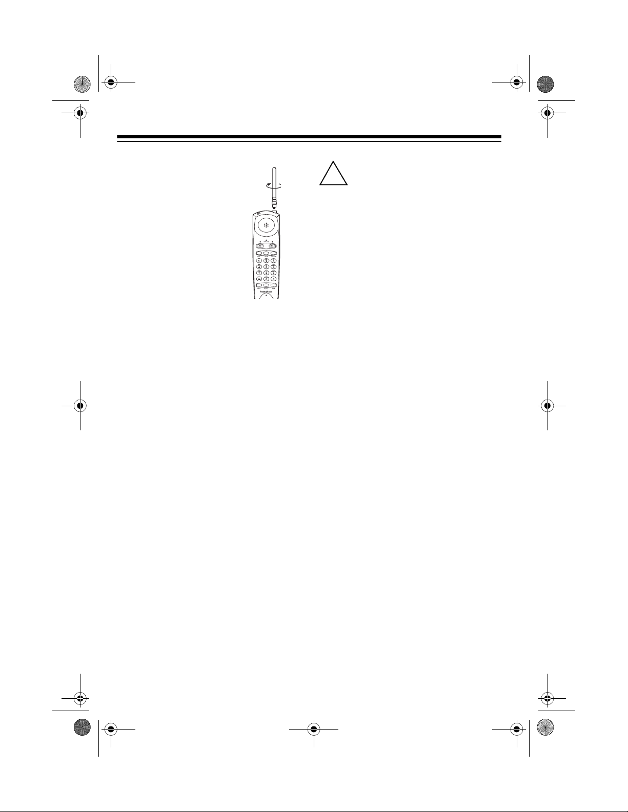
INSTALLING THE
HANDSET’S
ANTENNA
Insert the antenna into the
larger hole at the top of
the handset, then sc rew in
the antenna clockwis e until it is secure.
SELECTING A LOCATION
You can place the phone on a desk or
table, mount it on a standard wall pla te,
or mount it directly on a wall. Select a location that is:
• near an easily accessible AC outlet
• near a modular telephone line jack
• out of the way of normal activities
• away from electrical machinery,
electrical appl iances, metal walls or
filing cabinets, wireless intercoms,
alarms, and room monitors
• away from other cordless phones
The base’s location affects the handset’s range. If you have a choi ce of several locations, try each to see which
provides the best performance.
Caution:
2 power source that supplies
12 volts DC and delivers at
least 300 mA. Its cent er tip must be set
to positive and its plug must fit the
base's
er meets these specificati ons. Using an
adapter that does no t meet thes e spec ifications could dam age the base or the
adapter. You ca n connect your ET-689
to a 2-line modu lar teleph one j ack us ing
one of the supplied 2-line modular
cords. Or, you can connect your telephone to two separate 1-line modular
telephone jacks using the supplied 2line modular cords.
Notes
DC 12V jack. The sup plied ada pt-
:
• Your telephone connects directly to
a modular telephone line jack. If
your phone line jack is not a modular
jack, you can update the wiring
yourself, using jacks and adapters
available at your local RadioShack
store. Or, you can let the phone
company update the wiring for you.
• The USOC number of the two-line
jack to be installed is RJ14C (or
RJ14W for a wall plate jack). The
USOC number for a single -line jack
is RJ11C (or RJ11W for a wall plate
jack).
You must use a Class
6
43-689.fm Page 7 Thursday, September 16, 1999 10:22 AM
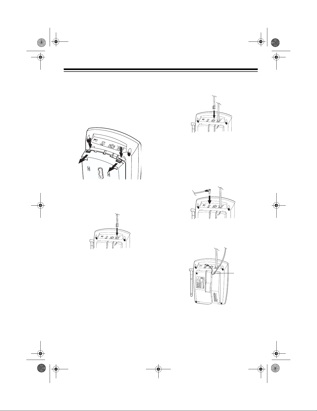
MOUNTING THE PHONE
On a Desk Top
1. Remove the base’s bracket by
pressing both tabs on the wide e nd,
then lifting off the bracket.
2.
If you have a single 2-line modular
jack,
plug one end of the supplied 2-
line long modular cord into
L2
on the back of the phone’s base.
L1 OR L1/
plied 2-line long modular cord into
L2.
If you have a single 1-line modular
jack,
plug one end of either supplie d
long modular cord i nto
L1 OR L1/L2
to use line 1, or into L2 to use line 2.
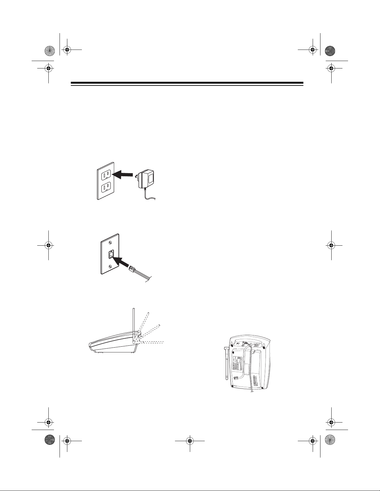
3. Plug the supplie d AC adapter’s barrel plug into the
DC 12V jack on the
back of the phone’s base.
4. Route the adapter’s cord through
the right groove on the bottom of the
base.
Note:
When you make this connection, do not connect another modular cord to the
L2 jack. Otherwise,
the phone will not operate properly.
If you have two separate 1-line modular jacks,
plug one end of the sup-
plied 2-line long modular cord into
L1 OR L1/L2 and plug the other sup-
7
43-689.fm Page 8 Thursday, September 16, 1999 10:22 AM
5. Insert the tabs on the na rrow end of
the bracket into the lower slots on
the base’s bottom, then push the
tabs on the wide end of the bracket
into the other slots until the bracket
clicks securely into place.
6. Plug the AC adapter into a s tandard
AC outlet.
7. Plug the other end(s) of the modu la r
cord(s) into the modular telephone
jack(s).
8. Lift the base’s antenna to a vertical
position.
On a Wall Plate
1. Remove the base’s bracket by
pressing both tabs on the wid e end,
then lifting off the bracket.
2.
If the wall plate has a single 2-line or
1-line modular ja ck,
the supplied 2-line short modular
cord into
L1 OR L1/L2 on the back of
the phone’s base.
Note:
When you make this connection, do not connect a nother modular cord to the
the phone will not operate properly.
If the wall plate has a single 1-line
modular jack, and there is another
modular telephone jack close by,
plug one end of the supplied 2-line
short modular cord into
and plug the supplied 2-line long
modular cord into
3. Plug the supplie d AC adapter’s barrel plug into the
back of the phone’s base.
4. Route the AC adapter’s cord
through the right groove on the bottom of the base. Route the short
modular cord through the left groove
on the bottom of the base.
plug one end of
L2 jack. Otherwise,
L1 OR L1/L2,
L2.
DC 12V jack on the
8

3
43-689.fm Page 9 Thursday, September 16, 1999 10:22 AM
If you need to connect a long m odular cord to the
L2 jack, r emove the
short modular cord from the left
groove and route the long modular
cord through the groove on the bottom of the base.
5. Route the end of the shor t modular
cord through the h ole in the center
of the bracket, then insert the tabs
on the narrow end of the bracket into
the upper slots on the base’s bottom.
6. Route the adapter cord and the lo ng
modular cord (if you have connected
it) through each slot on the bottom
of the wide end of the bracket, then
push the tabs on the wide end of the
bracket into the other slots unti l the
bracket clicks securely into place.
7. Plug the AC adapter into a s tandard
AC outlet.
8. Plug the short modular cord i nto th e
wall plate jack, then align the base ’s
keyhole slots with the wall plate
studs and slide the base downward
to secure it.
If you attached a long modular co rd,
plug it into the other phone line jack.
9. Lift the base’s antenna to a ver tical
position.
Directly on a Wall
For this mounting method, you need two
screws (not suppl ied) with heads th at fit
into the keyhole slots on the mounting
bracket.
16
315/
/
16
1. At the desired mounting
location, drill two holes
15
3
/16 inches (100 mm)
apart vertically. Then
thread a screw into each
hole, letting the heads
extend about
3
/16 inch (5
mm) from the wall.
2. Remove the bracket by holding in
both tabs on the wide end, then gently pulling out the wide end of the
bracket.
9

43-689.fm Page 10 Thursday, September 16, 1999 10:22 AM
3.
If you have a single 2-line modular
jack,
plug one end of the supplied
long 2-line modu lar cord into
L1/L2
on the back of the phone’s
base.
Note:
When you make this connection, do not connect another modular cord to the
the phone will not operate properly.
L2 jack. Otherwise,
L1 OR
If you have two separate 1-line modular jacks,
plied 2-line long modular cord into
L1 OR L1/L2 and plug the supplied 2-
line long modular cord into
plug one end of the sup-
L2.
If you have a single 1-line modular
jack,
plug one end of either suppli ed
long modular cord into
to use line 1, or into L2 to use line 2.
4. Plug the supplied AC adapter’s barrel plug into the
5. Route the adapter’s cord through
the right groove on the bottom of the
base. Route the long modular cord
through the left groove on the bottom of the base.
If you have connected two long
modular cords, route the cord connected to
right groove on the bottom of the
base, and route the cord connected
to
L2 through the ho le in the center
of the bracket.
6. Insert the tabs on the na rrow end of
the bracket into the slots on the
base’s bottom as shown, then push
the tabs on the wide end of the
bracket until it clicks securely into
place.
DC 12V jack.
L1 OR L1/L2 through the
L1 OR L1/L2
7. Plug the AC adapter into a standar d
AC outlet.
8. Plug the other end(s) of the cord(s)
into a modular phone line jack(s).
9. Align the base’s keyhole slots with
the mounting screws and slide the
base downward to secure it.
10. Lift the base’s antenna to a vertical
position.
CONNECTING AND
CHARGING THE BATTERY
PACK
The ET-689 comes wit h a rechargeable
nickel-cadmium battery pack in the
handset but not connected. Before using
your phone, you mus t connect the battery pack, then charge it for about 15
hours.
1. Press down and slid e off the batte r y
compartment cover.
10

43-689.fm Page 11 Thursday, September 16, 1999 10:22 AM
2. Remove the battery pack and plug
its connector into the phone’s
socket. The connector fits only one
way.
Notes:
3. Put the battery pack back in the
compartment, then replace the
cover.
To charge the battery pack, place the
handset on the base either face up or
face down. The CHARGE indicator on
the base lights.
Note
: The battery pack will
not
fully
charge when you place the handset on
the base face up.
Recharge the battery pack when the
BATT LOW indicator on the handset
flashes.
• If the CHARGE indicator does
not
light when you place the handset on
the base, be sure the battery pack
and AC adapter are correctly and
securely connected. Even if they
are, your handset’s battery power
still might be low. Wait 3 minutes.
The CHARGE indicator should light.
• After charging or recharging the battery pack, the phone mi ght not work
and you might hear an error tone. If
this happens, return the handset to
the base for a few seconds.
• If the battery pack gets completely
discharged or the bas e loses power
while the handset is away from it, reset the security access-protection
code by placing the handset on the
base. If the handset lost power,
leave the handset on the base to
charge the battery pack.
• Using a pencil eraser, clean the
charging contacts on the handset
and the base about once a month to
make sure they are not dirty or tarnished.
11

43-689.fm Page 12 Thursday, September 16, 1999 10:22 AM
• If the BATT LOW indicator does not
light, but the phone does not wor k,
recharge the batte ry pack. (The battery pack charge might be too low to
light the indicator.)
• If the battery pack gets weak during
a call, the handset sounds 4 beeps
every 30 seconds and the BATT
LOW indicator flashes for 4 minutes.
After 4 minutes, the phone automatically disconnects. If this happens,
you must recharge the batter y pack
before you can make another call.
• About once a month, fully discharge
the battery pack by keeping the
handset off the base until the BATT
LOW indicator lights. Oth erwise, the
battery pa ck loses its a bility to fully
recharge.
SETTING THE DIALING
MODE
3. When you hear the dia l tone, press
any number other than
Note:
If your phone system req uir es
that you dial an access cod e (9, for
example) before you dial an outside
number, do not press the access
code .
If the dial tone stops, that line has
tone service.
If the dial tone continues, that line
has pulse service.
4. Press
LINE 2, listen for the dial tone,
and repeat Step 3.
If you have tone service on both
lines, leave
If you have pulse service on either
line, set
T/P set to T.
T/P to P.
0.
TURNING THE RINGER
ON/OFF
Set T/P (ton e/pulse) on the back of the
base for the type of s ervice you ha ve. If
you are not sure which type you have,
once the battery pack is charged, do this
test.
1. Set
2. Lift the handset and press
12
T/P to T.
LINE 1.
You can turn th e ET-689 ’s
ringer on and off. Set
RINGER on the side of the
handset to
incoming call or a page
from the base. Set
ER
to OFF to silence the
ringer.
Note
: Even if you turn off the ringe r on
the handset, you can still make or receive calls using this cordless phone.
Telephones on the same line still ring
when there i s an incoming call, and th e
line indicator on the ET-689’s base
flashes until you answer the call.
ON to hear an
RING-

43-689.fm Page 13 Thursday, September 16, 1999 10:22 AM
OPERATION
MAKING/ANSWERING
CALLS
To make a call, pi ck up t he handset a nd
press
LINE1 or LINE 2 to select the line
you want to use. When the line indicato r
lights steadily and you hear the dial
tone, dial the phone number.
To answer a call if the handset is on the
base, simply lift the handset and begin
your conversation.
To answer a call if the handset is not on
the base, press
pending on which line indicat or is flashing.
LINE 1 or LINE 2 de-
(see “Putting a Call on Hold” on
Page 15 ), th en pr es s the other line’s
button to answer the incoming call.
• If you move the handset outside the
base’s range (about 300 feet of
unobstructed space) the handset
will not operate properly and a call in
progress might be disconnected.
CHANGING THE
CHANNEL
The ET-689 scans 20 channels (frequency pairs used between the base
and the handset) and automatic ally selects a clear channel each time you
make or receive a call.
If you hear other conversations or excessive noise during a call, press
NEL
to select a different channel.
CHAN-
To end a call, place the handse t on the
base or press the line button for that
line.
Notes:
• If you press the line button to hang
up and the phone does not disconnect, press the line button again
while holding the handset closer to
the base, or place the handset on
the base.
• When you receive an incoming call
on one line whil e you are talking on
the other, the handset does not r ing
but you hear a tone through the earpiece. Place the current call on hold
Each time you press
cator for the line you use blin ks as your
phone searches for a clearer channel.
Note
: If the handset is too fa r from the
base, the channel might not change.
Move closer to the base and try again.
CHANNEL, the indi-
13

43-689.fm Page 14 Thursday, September 16, 1999 10:22 AM
ADJUSTING THE
HANDSET’S VOLUME
The ET-689 has three volume levels. T o
change the volume you hear through the
handset, press
side of the handset to increase or decrease the volume during a call.
VOLUME ▲ or
▼
on the
USING REDIAL
You can quickly dial the la st number di aled on a line. Press the button (
or LINE 2) for the line you want to use,
then press
tone.
REDIAL when you hear a dial
LINE 1
• The redial memor y do es not s tore a
flash entry or any digits you press
after
FLASH (see “Using Flash”).
USING FLASH
FLASH performs the electronic equiva-
lent of a switchhook operation for special services such as Call Waiting.
For example, if you have Call Waiting,
press
FLASH to answer an incoming call
without disconnecting the current call.
Press
FLASH again to return to the first
call.
Note:
phone services, pressing
disconnect the curren t call .
If you do not have any special
FLASH might
Notes:
• The redial memory holds up to 24
digits, so you can redial long-distance as well as local numbers.
• The redial memory also holds pause
entries. See “Entering a Pause” on
Page 17.
14

43-689.fm Page 15 Thursday, September 16, 1999 10:22 AM
PUTTING A CALL ON
HOLD
Press HOLD to put a call on hold so y ou
can use the other phone line without disconnecting the current call. The line indicator flashes when a call on th at line is
on hold.
Note:
Do not return the handset to the
base while a call is on ho ld. Placing the
handset on the base after you press
HOLD disconnects the call.
To release a line from hold and continue
your conversation, press that line’s button.
Note
: If you do not pick up the call again
within 3 minutes af ter putting it on hold,
the phone disconnects the call.
You can alternate between th e two line s
by pressing
desired line.
Note:
without first pressing
is disconnected.
HOLD then the button for the
If you press the other line’s button
HOLD, the first call
CONFERENCE CALLING
Follow these steps to have a 3-way conference call.
1. Place the first call on hold.
2. Make or answer a call on the other
line.
3. Press
briefly flash then light steadily. All
three parties are connected.
Note
long-distance cal ls might sound weaker
than local calls.
To talk on only one line without dis connecting the other line, press
both lines on hold. Then press the button for the line you want to talk on.
To return to a three-way conversation,
press
To end the co nference call, pr ess
or return the handset to the base.
To hang up one line and continue talking
on the other, press the line button for the
line you want to keep using.
CONF. Both line indicators
: During conference calls, some
HOLD to put
CONF.
CONF
15

43-689.fm Page 16 Thursday, September 16, 1999 10:22 AM
USING TONE SERVICES
ON A PULSE LINE
Some special services, such as bankby-phone, require tone signals. If you
have pulse service, you can still use
these special tone serv ices by following
these steps.
1. Be sure
2. Dial the service’s main number.
3. When the service answers, press
are sent as tone signals.
4. After you complete the call, return
the handset to the base or press the
button for the line you were using.
The phone automatically resets to
the pulse mode.
T/P is set to P.
. Any additional numbers you dial
If you hold down
the handset beeps for 3 minutes t o give
you more time to locate it. To stop it
sooner, press
button twice.
PAGE for 2 seconds,
PAGE once or either line
MEMORY DIALING
You can store up to 20 numbers, then
dial any of the stored numbers by pressing a two-digit memory location number.
Each stored number can be up to 24
digits long.
Storing a Number in Memory
Note:
If you wait more than 20 seconds
between each key press, an error tone
sounds and the phone exits the storing
mode.
1. Press
LINE 1 indicator flashes.
MEM on the handset. The
PAGING
To locate the handset when the phone is
not in use, press
handset beeps three times.
16
PAGE on the ba se . The

43-689.fm Page 17 Thursday, September 16, 1999 10:22 AM
2. Enter the number and any tone a nd
pause entries ( see “ Us ing Tone Services on a Pulse Line” on Page 16
and “Entering a Pause”).
Note:
Each tone or pause entry
uses one digit of memory.
3. Press
To replace a stored number, simply
store a new number in its place.
Or, to clear a memory location, skip
Step 2, then enter the memory loc ation
number (01–20) you want to clear. A
tone sounds.
MEM, then enter the memor y
location number (01–20). The
phone pauses to confir m that each
digit was stored, then it beeps to
indicate that the number is stored.
Note
: If three quick beeps sound,
you have made an error and the
number was not stored. Star t again
from Step 1.
Entering a Pause
In some telephone systems, you must
dial an access code (9, for example) and
wait for a second dial tone before you
can dial an outside number. You can
store the access code with the phone
number. However, you should also store
a pause after the acc ess code to allow
the outside line time to connect.
Dialing a Memory Number
To dial a numbe r stored in memory, lift
the handset and pr ess th e b utto n f or th e
line you want to use.
When you hear a dial tone, pr ess
and enter the memory location number
for the number you want to dial.
MEM
Chain-Dialing Service Numbers
When calling sp ecial services (such as
alternate long distance or bank-byphone), dial the s ervice’s main number
first. Then, at the appropriate place in
the call, press
the memory location w her e t he a ddi ti onal information is stored.
MEM and the number for
Testing Stored Emergency
Numbers
If you store an emergency service’s
number (police d epartment, fire department, ambulance) and you choose to
test the stored number, make the test
call during the late evening or early
morning hours to avoid peak demand
periods. Also, remain on the line to explain the reason for your call.
To enter a 3-second pause , press
AL
after entering th e a cces s code. For a
longer pause, press
REDIAL again.
REDI-
17

43-689.fm Page 18 Thursday, September 16, 1999 10:22 AM
USING A HEADSET
You can make or answer calls with
hands-free convenience using an optional headset that has a
mm) plug, available at your local RadioShack store.
To connect the headset, insert the head-
3
set’s
/32-inch (2.5 mm)
plug into the jack
marked on the top
of the handset.
Notes
:
• Connecting a headset disconnects
the handset’s earpiece and microphone.
3
/32-inch (2.5-
•
VOLUME ▲/
on the handset also
▼
controls the connected headset’s
volume.
• If you place the handset on the base
to recharge it while the headset is
connected, be sure the handset
seats properly.
With a headset c onnected, you mak e or
answer calls as usual us ing the keys on
the handset.
For hands-free conversation, you can
use a handset ho lder, available at your
local RadioShack store, to hang the
handset on your belt.
18

43-689.fm Page 19 Thursday, September 16, 1999 10:22 AM
TROUBLESHOOTING
We do not expect you to hav e any proble ms with you r ET-689, but if y ou do, the following suggestions might help.
Problem Suggestion
Low volume or unusual
sounds.
Severe noise interference. Keep the handset away from computers,
The phone cannot be operated at a useful distance from
the base because the signal
becomes weak or noisy (the
handset’s range has
decreased).
The phone does not work or
works poorly.
The handset battery pack
does not charge.
Someone has picked up another phone on the
same line. Hang up the other phone.
remote control toys, wireless microphones,
alarm systems, intercoms, room monitors, fluorescent lights, and electrical appliances.
Press
CHANNEL to change the channel.
Hang up and redial the number.
Fully extend the base’s antenna, and place it in
a vertical position.
Be sure neither antenna is touching a metal
surface.
Return the handset to the base to recharge the
battery pack.
Be sure the base’s phone line cord and AC
adapter are correctly and securely connected,
and the battery pack is connected and
charged.
Be sure the battery pack is properly connected.
Check the charging contacts on the handset
and base. If they are dirty, clean them with a
pencil eraser.
Replace the battery pack. (See “Replacing the
Battery Pack” on Page 22.)
19

43-689.fm Page 20 Thursday, September 16, 1999 10:22 AM
Problem Suggestion
The handset does not ring or
receive a page.
The handset stops working or
works poorly during a call.
Fully extend the base’ s anten na and pl ace it in
a vertical position.
Move the handset closer to the base.
Move the base away from other electrical
devices.
Return the handset to the base to recharge the
battery pack.
Move the handset closer to the base.
Fully extend the base’ s anten na and pl ace it in
a vertical position.
Return the handset to the base for 6 seconds
to reset the handset.
Be sure the handset’s battery is charged. (If
the battery power is too low, it might not have
enough power to light th e BATT LOW indicator.)
If the base loses power while the handset is
away from it, the security access-protection
code might change. Restore power to the
base, then place the handset back on the
base. The CHARGE indicator on the base
lights, indicating that the code is set again.
The indicators for Lines 1 and
2 on your handset flash, but
there is no dial tone.
The Line 1 or Line 2 indi cator
continuously flashes when you
Check that the phone line cord(s) and the AC
adapter are properly connec te d at both ends.
Check to see if both lines are on hold.
Only one phone line is connected. Check that
both phone lines are properly connected.
are not using the phone.
If you still have problems, di sconnect the phone. If other phones on the sa me line(s)
work properly, the fault is in this phone or its installa tion. If you cannot fin d the problem, take your phone to your local RadioShack store for assistance.
20

43-689.fm Page 21 Thursday, September 16, 1999 10:22 AM
CARE AND MAINTENANCE
Your RadioShack ET-689 900 MHz Two-Line Cor dless Telephon e is an exampl e of
superior design and craftsmanship. The following suggestions will help you care for
your cordless telephone so you can enjoy it for years.
Keep the phone dry. If it gets wet, wipe it dry immediately. Liquids might
contain minerals that can corrode the electronic circuits.
Use and store the phone only in normal temperature environments.
Temperature extreme s can shorten the life of electronic devices an d
distort or melt plastic parts.
Keep the phone away from d ust and dirt, wh ich can cause p remature
wear of parts.
Handle the phone gently and ca refully . Dropping it can damag e circui t
boards and cases and can cause the phone to work improperly.
Wipe the phone with a damp cloth occasionally to keep it looking new.
Do not use harsh chemicals, cleaning solvents, or strong detergents to
clean the phone.
Modifying or tampering with the telephone’s intern al components can cause a ma lfunction and might invalidate your telephone’s warranty and void your FCC authorization to operate it. If your ph one is not performing as it should, take it to your local
RadioShack store for assistance. If the trouble is affecting the phone lines, the phone
company might ask y ou to disconnect yo ur phone until you h ave resolved the p roblem.
21

43-689.fm Page 22 Thursday, September 16, 1999 10:22 AM
REPLACING THE
BATTERY PACK
If you follow the instructions in “Connecting and Charging t he Battery Pack” on
Page 10, the battery pack should last
about a year. If the battery pac k will not
hold a charge for mo re than 2 hours after an overnight charge , repl ac e the bat tery pack with a new 3.6V, 600 mAh
battery pack with a connector that fits
the socket in the battery compartment.
You can order a replacement battery
pack through your local RadioShack
store.
Install the new battery pack as described below, then charge the battery
pack for about 15 hours before you use
it.
1. Press down and slide off the bat ter y
pack cover as shown.
3. Plug the fresh battery pack’s connector into the pho ne’s socket. The
connector fits only one way.
4. Put the new battery pack in the compartment, then replace the cover.
Cautions:
• You must use a replac ement b atter y
pack of the same size and type.
• Do not dispose of the battery pack
in a fire because it might explode.
• Do not open or mutilate the batte ry
pack.
• Be careful not to short the battery
pack by touching it with conducting
materials, such as rings, bracelets,
and keys. The battery pack or conductor might overheat and burn.
2. Gently pull on the batter y pack connector to disconnect it, then re move
the battery pack.
22
Important:
chargeable nickel cadmium battery pack.
At the end of the battery pack’s use ful life,
it must be recycled or disposed of properly. Contact your local , county, or state h azardous waste management authorities for
information on recycling or disposal programs in your area. Some options that
might be available are: municipal curbside collection, drop-off boxes at retailers
such as your local RadioShack store, recycling collection centers, and mail-back
programs.
This product contains a re-

43-689.fm Page 23 Thursday, September 16, 1999 10:22 AM
THE FCC WANTS YOU TO
KNOW
In the unlikely event that your phone
causes problems on the phone line, the
phone company can t emporar ily disc ontinue your service. If this happens, the
phone company attempts to notify you in
advance. If advance notice i s not pr actical, the phone compan y notifies you as
soon as possible and advises you of
your right to file a complaint with the
FCC.
Also, the phone company can make
changes to its lin es, equipment, operations, or procedures that could affect the
operation of this telephone. The telephone company notifies you of these
changes in advance, so you can take
the necessary steps to prevent interruption of your telephone service.
Your phone might cause TV or radio interference even when it is operating
properly. To determine whether your
phone is causing the interference, turn
off your phone. I f the interference goes
away, your phone is causing the interference.
If you cannot eliminate t he interference ,
the FCC requires that you stop using
your phone.
Some cordless phones operate at frequencies that might cause interference
to nearby TVs and VC Rs. To minimize
or prevent such interference, the base of
the cordless phone should not be placed
near or on top of a TV or VCR.
LIGHTNING
Your telephone has built-in lightning protection to reduce the risk of damage
from surges in teleph one li ne an d po wer
line current. This lightning protection
meets or exceeds FCC requirements.
However, lightning striking the telephone or power lines can damage your
telephone.
Lightning damage is not c ommon. Nevertheless, if y ou live in an area that has
severe electrical storms, we suggest
that you unplug your phone during
storms to reduce the possibility of damage.
Try to eliminate the interference by:
• moving your phone away from the
receiver
• connecting your phone to an AC
outlet that is on a different electri cal
circuit from the receiver
• contacting your local RadioShack
store for help
23

43-689.fm Page 24 Thursday, September 16, 1999 10:22 AM
Limited One-Year Warranty
This product is warrante d by RadioSha ck against manufac turing defect s in material and wor kmanship under normal use for one (1) year from the date of purchase from RadioShack company-owned
stores and authorized RadioShack franchisees and dealers. EXCEPT AS PROVIDED HEREIN, RadioShack MAKES NO EXPRESS WARRANTIES AND ANY IMPLIED WARRANTIES, INCLUDING
THOSE OF MERCHANTABILITY AND FITNESS FOR A PARTICULAR PURPOSE, ARE LIMITED
IN DURATION TO THE DURATION OF THE WRITTEN LIMITED WARRANTIES CONTAINED
HEREIN. EXCEPT AS PROVIDED HEREIN, RadioShack SHALL HAVE NO LIABILITY OR RESPONSIBILITY TO CUSTOMER OR ANY OTHER PERSON OR ENTITY WI TH RESPECT TO ANY
LIABILITY, LOSS OR DAMAGE CAUSED DIRECTLY OR INDIRECTLY BY USE OR PERFORMANCE OF THE PRODUCT OR ARISING OUT OF ANY BREACH OF THIS WARRANTY, INCLUDING, BUT NOT LIMITED TO, ANY DAMAGES RESULTING FROM INCONVENIENCE, LOSS
OF TIME, DATA , PROPERTY, REVENUE, OR PROFIT OR ANY INDIRECT, SPECIAL, INCIDENTAL, OR CONSEQUENTIAL DAMAGES, EVEN IF RadioShack HAS BEEN ADVISED OF THE
POSSIBILITY OF SUCH DAMAGES.
Some states do not allow the limitations on how long an implied warranty lasts or the exclusion of incidental or consequential damages, so the above limitations or exclusions may not apply to you.
In the event of a pr oduct defect durin g the warranty pe riod, take the pro duct and the RadioShack
sales receipt as proof of purchase date to any RadioShack store. RadioShack will, at its option, unless otherwise provid ed by law: (a) correct the def ect by p rod uct repair without charge for pa rts a nd
labor; (b) replace the product wi th one of the same or similar design; or (c) refund the purch ase
price. All replace d parts a nd prod ucts, and p roducts o n which a refund is made, become th e property of RadioShack. New or recond itioned parts a nd products may be used in the performance of
warranty service. Re paired or replace d parts and pro ducts are warran ted for the rem ainder of the
original warranty period. You will be charged for repair or replacement of the product made after the
expiration of the warranty period.
This warranty does not cover: (a) damage or failure caused by or attributable to acts of God, abuse,
accident, misuse, i mproper or abnormal usag e, fa ilu re to fo llow instr uctio ns, improper installat ion or
maintenance, altera tion, lightning or othe r incidence of excess voltage or current; (b ) any repairs
other than those provided by a RadioShack Authorized Service Facility; ( c) consumables such as
fuses or batteries; (d) cosmetic dam age; (e) tra nsportation , shipping or insurance costs; or (f) costs
of product removal, installation, set-up service adjustment or reinstallation.
This warranty give s you specific l egal rights, an d you may al so have other r ights which var y from
state to state.
RadioShack Customer Relations, 200 Taylor Street, 6th Floor, Fort Worth, TX 76102
We Service Wh at We Sell
04/99
RadioShack
A Division of Tandy Corporation
Fort Worth, Texas 76102
06A99 Printed in China
 Loading...