


43-652 .fm Page 1 Friday, August 13, 1999 11:00 AM
Cat. No. 43-652
OWNER’S MANUAL
Please read before using this equipment.
ET-652
Two-Line Speakerphone

y
g
g
g
g
y
g
CAUTION
43-652 .fm Page 2 Friday, August 13, 1999 11:00 AM
FEATURES
Your RadioShack ET-652 Two-Line
Speakerphone lets you make or receive
calls on two separate telephone lines
using either the handset or the built in
speakerphone. You can connect up to
five ET-652s to the same t elephone line
(depending on the phone line’s power;
see “Read This Before Installation” on
Page 3).
Your ET-652 has these features:
Line Status Indicators
— let you see at
a glance if a line is available, in use, or
on hold.
20-Number Memor
Dialin
— lets you
store up to 20 numbers in memory for
easy dialing.
Distinctive Rin
— tells you w hich line
is ringing.
Redial
— lets you quickly redia l the last
number dialed.
— sends an electronic switch-
Flash
hook signal for use with special phone
services, such as Call Waiting.
— lets you put one or both lines on
Hold
hold with a separate indicator for each
line.
Tone or Pulse Dialin
— lets you use
your phone with tone or pulse (rotary) dialing and lets you switc h from pulse to
tone dialing for long-distance, bank-byphone, or other special services.
Hearin
-Aid Compatibilit
— lets you
use your phone with hearing aids that
have a T (telephone) switch.
Your ET-652 has been teste d and found
to comply with all applicable standards.
Warnin
: To prevent fire or s hock
hazard, do not expose this product
to rain or moisture.
RISK OF ELECTRIC SHOCK.
DO NOT OPEN.
CAUTION
ELECTRIC SHOCK, DO NOT REMOVE
COVER OR BACK. NO US ER-SERVICEABLE PARTS INSIDE. REFER SERVICING TO QUALIFIED PERSONNEL.
: TO REDUCE THE RISK OF
This symbol is intended to alert you to
the presence of uninsulated dangerous voltage within the prod uct’s enclosure that might be of sufficient
magnitude to constitute a risk of electric sh ock. Do n ot open the prod uct’s
case.
!
Volume Control
volume you hear through the handset.
Speakerphone
— lets you adjust the
— lets you make or an-
This symbol is intended to inform you
that important operating and mainte-
!
nance instructions are included in the
literature accompanying this product.
swer calls without using the handset.
© 1998 Tandy Corporation.
RadioShack is a registered trademark used by Tandy Corporation.
All Rights Reserved.
2

43-652 .fm Page 3 Friday, August 13, 1999 11:00 AM
READ THIS BEFORE
INSTALLATION
Your ET-652 conforms to federal regulations, and you can connect it to most
telephone lines. However, each device
that you connect to the telephone line
draws power from the line. We refer to
this power draw as the device’s
equivalence number
is on the bottom of the base.
If you are using more than one phone or
other device on the line, add up all the
RENs. If the total is mo re than five, your
phones might not ring. In rural areas, a
total REN of three might impair ringer
operation. If ringer operation is impaired,
remove a device from the line.
, or REN. The REN
ringer
FCC STATEMENT
This telephone complies with Part 68 of
FCC Rules
provide the FCC registration number
and the REN to your telephone com pany. Both numbers are on t he bottom of
the telephone.
Note:
to any of the following:
• coin-operated systems
• party line systems
• most electronic key phone systems
We recommend you record your
phone’s serial number here. The number is on the bottom of the base.
Serial Number __________________
. You must, upon request,
You must not connect your phone
3

g
43-652 .fm Page 4 Friday, August 13, 1999 11:00 AM
CONTENTS
Installation ............................................................................................................... 5
Mounting the Phone ........................................................................................... 5
Connecting the AC Adapter ......................................................................... 5
Connecting to the Phone Lines .................................................................... 5
Connecting the Handset .............................................................................. 6
Mounting on a Wall or Wall Plate ................................................................. 7
Setting the Dialing Mode .................................................................................... 8
Setting the Ringer Volume .................................................................................. 8
Setting the
Confirming the Line Numbers ............................................................................. 9
Checking/Adjusting the Line-Status Indicators ................................................... 9
Operation ............................................................................................................... 11
Making and Answering Calls ............................................................................ 11
Setting the Volume ........................................................................................... 11
Switching Between the Handset and the Speake rphone ................................. 11
Using
Using
Using
Using Tone Services on a Pulse Line ............................................................... 13
Memory Dialing ................................................................................................ 13
Entering a Pause ....................................................................................... 14
Dialing a Memory Number ......................................................................... 14
Chain-Dialing Service Numbers ................................................................. 14
NORM/STORE
HOLD
...................................................................................................... 12
REDIAL
FLASH
................................................................................................... 12
.................................................................................................... 12
Switch ........................................................................ 8
Troubleshootin
.................................................................................................... 15
Care and Maintenance .......................................................................................... 16
The FCC Wants You to Know ........................................................................... 17
Lightning ........................................................................................................... 17
4

43-652 .fm Page 5 Friday, August 13, 1999 11:00 AM
INSTALLATION
MOUNTING THE PHONE
You can place the ET-652 on a desk or
table, mount it on a s tandard wall plate,
or mount it directly on a wall. Choose a
location that is:
• near an AC outlet
• near a modular telephone line jack
• out of the way of normal activities
Caution:
!
power source that supplies 9
volts DC and delivers at least 300 mA.
Its center tip must be set to negative,
and its plug must fit the ET-652's
jack. The supplied AC adapter meets
these specifications. Using an adapter
that does not meet the specifications
could damage th e ET-652 or the a dapter.
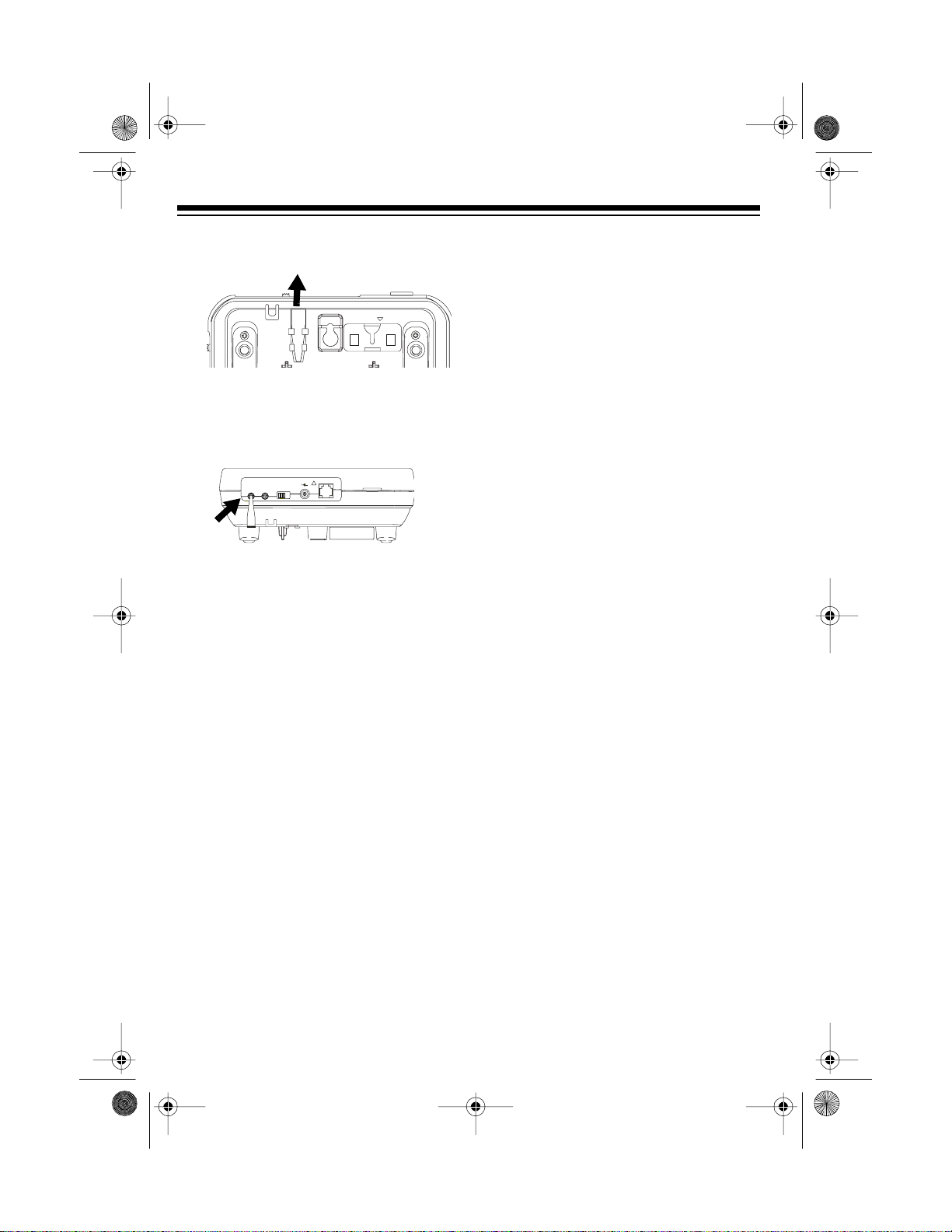
Connecting the AC Adapter
1. Insert the supplied AC adapter's
barrel plug into the
the back of the phone.
You must use a Class 2
9V DC
TEL LINE
DC9V
+!-
LINE 2 DEFEAT
ADJUST
OFF- ON
LINE1
LINE2
9V DC
jack on
2. Plug the adapter into a standard AC
outlet.
3. Route the adapter’s cord through
the strain relief slot on the bottom of
the phone.
Strain
Relief
Slot
DESK
Connecting to the Phone Lines
To take full advantage of the ET-652’s
capabilities, you must have two phone
lines with separate phone numbers. If
you have only on e line, y ou can order a
second from your phone company.
:
Notes
• The line that connects the phone
jack to the phone company wiring
must be twisted-pair cable. Otherwise, you might hear interference
(crosstalk) between the two lines.
• Your phone connects directly to a
modular phone line jack. If your
phone wiring does not have a modular jack, you can update it using
jacks and adapters available at your
local RadioShack store, or have the
phone company update it for you.
5

43-652 .fm Page 6 Friday, August 13, 1999 11:00 AM
• The USOC number of the two-line
jack to be installed is RJ14C
(RJ14W for a wall plate). The USOC
number of a single-line jack is
RJ11C.
Plug one end of the supplied two-line
telephone cord into the jack on the back
of the phone. Then plug the cord’s other
end into a modular telephone line jack.
MODE
NORM -STORE
PULSE -TONE
OFF LO HI
OFF LO HI
LINE1- RINGER - LINE2
If you use two single-line jacks, you
must connect the lines wi th an optional
two-line coupler (such as RadioShack
Cat. No. 279-401).
Note: If you use the ET-652 with only
one line, set
of the phon e to
LINE 2 DEFEAT
OFF
. This turns off Line
on the back
2’s status indicator.
TEL LINE
DC9V
+!-
LINE 2 DEFEAT
ADJUST
OFF- ON
LINE1
LINE2
OFFLO HI
LINE1- RINGER - LINE 2
OFFLO HI
MAX
VOLUME
MIN
Connecting the Handset
Plug the supplied coiled handset cord
into the j acks o n th e h andse t and the left
side of the phone.
6
OFFLO HI
LINE1- RINGER- LINE2
OFFLO HI
PULSE -TONE
MODE
NORM -STORE
Two-line
Coupler
Note: Your local RadioShack store sells
a variety of longer coiled handset cords,
which are especially useful when you
mount the phone on the wall.

®
CustomManufacturedinChina forRadioShack,
ADivisionof Tandy Corporation,FortWorth, TX76102
SerialNo.
COMPLIESWITHPART 68,FCCRULES
USEJACKUSOC RJ14C
CAT.NO.43-652
HAC
FCC REGISTRATION NO.AAOCHN-XXXXX-XX-X
RINGEREQUIVALENCE:0.9B
ET-652
CLASS 2POWERSUPPLY
TWO-LINESPEAKERPHONE
TELEPHONE
EQUIPMENT
POWER:DC 9V 300mA
®
L
I
S
T
E
D
TO190GDP00C
VOLUME
MIN
MAX
LINE1- RINGER- LINE2
OFFLO HI
OFFLO HI
MODE
PULSE -TONE
NORM -STORE
D
E
S
K
®
CustomManufacturedinChinaforRadioShack,
AD
i
v
is
iono
f
Ta
n
d
y C
o
rpo
r
a
t
ion
,
F
o
rtW
o
r
th,TX7
6
1
0
2
SerialNo.
COMPLIESWITHPART68,FCCRULES
USEJACKUSOCRJ14C
CAT.NO.43-652
H
AC
FCC REGISTRATION NO.AAOCHN-XXXXX-XX-X
RINGEREQUIVALENCE:0.9B
E
T
-6
52
C
LA
S
S
2
P
O
W
E
R
S
U
P
P
LY
TWO-LINESPEAKERPHONE
TELEPHO
NE
EQUIPMENT
POW
E
R
:D
C
9V
300mA
®
L
I
S
T
E
D
TO190GDP00C
43-652 .fm Page 7 Friday, August 13, 1999 11:00 AM
Mounting on a Wall or Wall
Plate
Notes:
• When mounting the ET-652 on a
wall plate, use the supplied short
modular cord to connect the phone
to the wall plate jack. Your local
RadioShack store carries a variety
of phone line cords.
• To mount the ET-652 directly on a
wall, you need two screws (not su pplied) with heads that fit the keyhole
slots on the bottom of the phone.
Drill two holes 3
inches (100 mm)
apart. Then thread a
screw into each hole,
letting the heads
extend about
(3 mm) from the wall.
1. Remove the mounting bracket from
DESK
the
socket by pressing in the
tabs on both sides and lifting. (You
might need to use a small screwdriver to press in the tabs.)
15
1
/8 inch
/
16
15
3
/16"
then push upward until the bracket
snaps into place.
3. Lift the handset holder and turn it
one half turn.
1
/8"
4. Place the phone's two keyhole slots
over the wall plate studs (or the
screws, if you are mounting the
phone on a wall). Press downward
on the phone to secure it.
D
E
S
K
2. Put the bracket into the
WALL
socket with the arrow on the bracket
aligned to the arrow by the socket,
7

43-652 .fm Page 8 Friday, August 13, 1999 11:00 AM
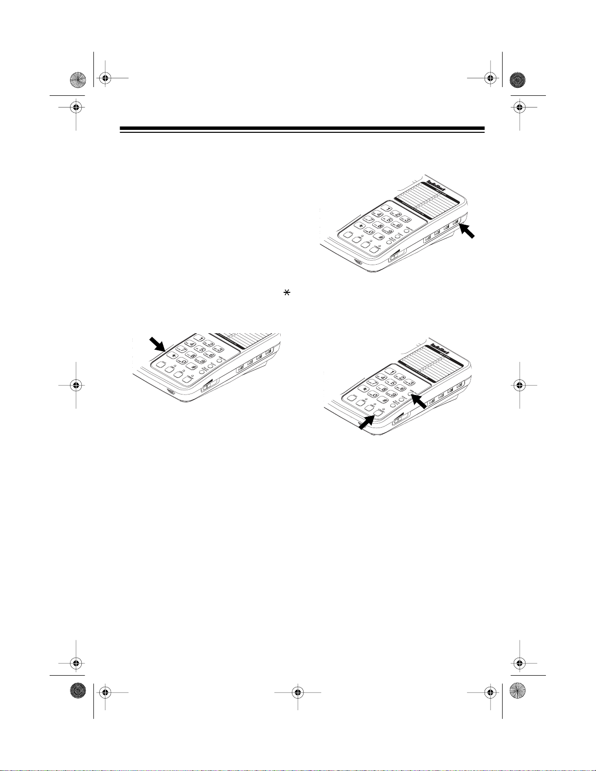
SETTING THE D IALING
MODE
MODE
Set
the type of service you have. If you are
not sure which type you have, do this
test.
1. Set
2. Press
3. Lift the handset and listen for a dial
tone .
4. Press any number other than
Note:
that you dial an access code (9, for
example) before you dia l an outside
number, do not press the access
code number either.
If the dial tone stops, you have
touch-tone service on Li ne 1. If the
dial tone continues, you have pulse
service.
on the side of the phone for
Line 1
OFFLO HI
LINE1- RINGER- LINE 2
OFFLO HI
MAX
VOLUME
MODE
Line 1
to
MIN
TONE
.
MODE
.
If your phone system requires
MODE
NORM -STORE
PULSE -TONE
0
.
SETTING THE RINGER
VOLUME
Each line on the E T-652 has a distinctive ring tone and a separate volume
control.
To change the rin ger volume, set
ER
for the desired li ne to
OFF, LO
RING-
, or HI.
With the ringer o ff, you can still answer
calls if you hear an extension phone ring
or see one o f the ET-652’s l ine indicators flash.
MODE
NORM -STORE
PULSE -TONE
OFFLO HI
LINE1- RINGER- LINE 2
OFFLO HI
MAX
VOLUME
MIN
SETTING THE NORM/
STORE SWITCH
NORM/STORE
The
store memory numbers (see “Memory
Dialing” on Page 13). Set it to
normal operation.
switch is used to
NORM
for
5. Hang up, then repeat the test for
Line 2.
6. If you have pu lse service on either
line, set
MODE
to
PULSE
. If you
have tone service on both lines,
leave the switch to
TONE
.
8
MODE
NORM -STORE
PULSE -TONE
OFFLO HI
LINE1- RINGER- LINE 2
OFFLO HI
MAX
VOLUME
MIN

g
g
g
g
43-652 .fm Page 9 Friday, August 13, 1999 11:00 AM
CONFIRMING THE LINE
NUMBERS
Follow these steps to determine which
phone number is connected to which
line.
LINE 1
1. Press
2. Dial one of yo ur phone numbers. If
the LINE 2 indicator flashes, the
number is connected to Line 2. If
you hear a busy signal, the number
is connected to Line 1.
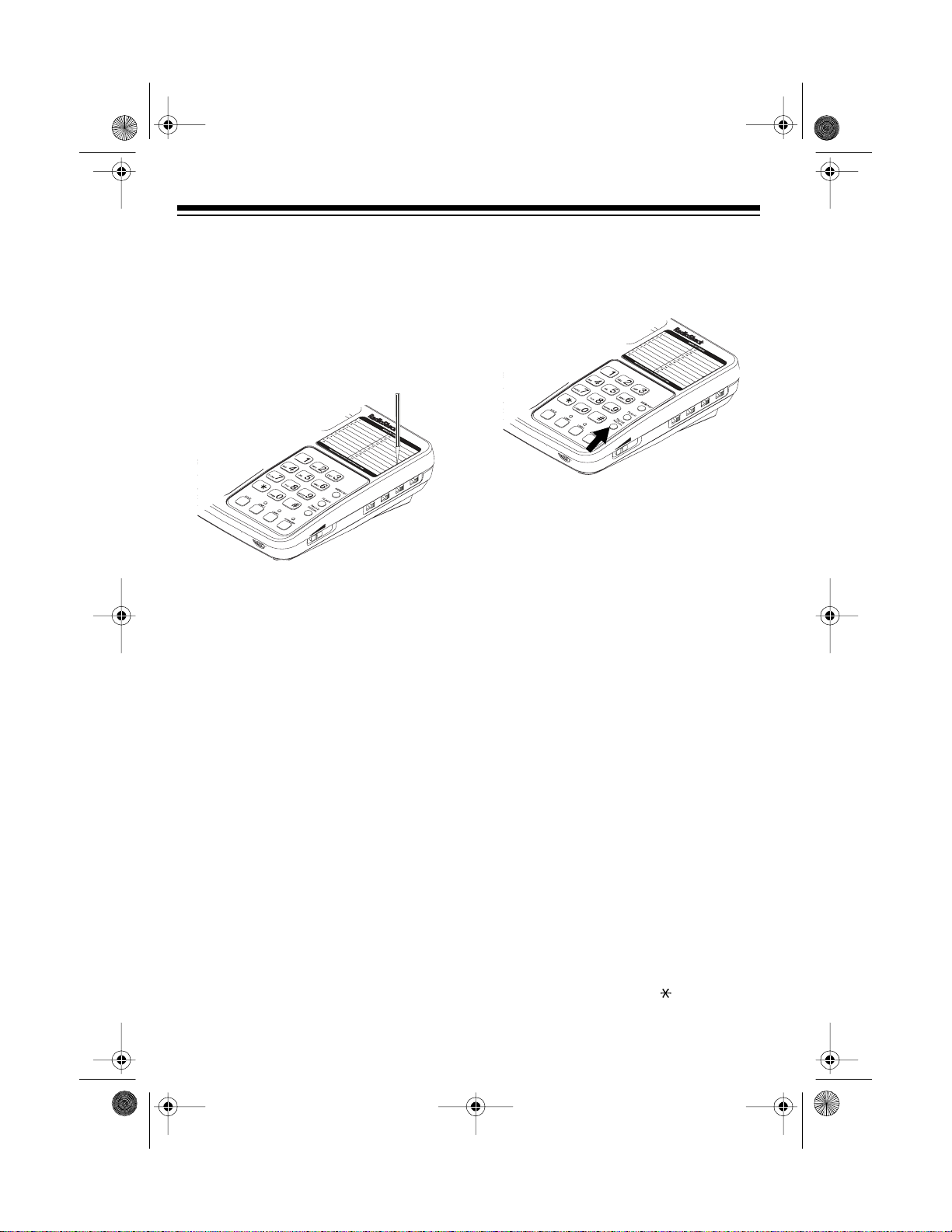
After you confirm the phone number for
each line, write the number on the number card above t he line-status indicator.
(Use a paper clip to lift off the card’s
cover.)
, then lift the handset.
MODE
NORM -STORE
PULSE -TONE
OFFLO HI
LINE1- RINGER- LINE 2
OFFLO HI
MAX
VOLUME
MIN
CHECKING/ADJUSTING
THE LINE-STATUS
INDICATORS
You can check the status of each line by
glancing at the line-status indicators.
Indicator is: Line is:
Not li
hted Not in use
hted In use
Li
Flashin
Flashing slowly On hold
Each line-status indicator is preset to
work correctly with most telephone lines.
However, in some cases you m ay need
to adjust the indicators to ensure correct
operation.
Follow these steps to test and adjust the
line-status indicators.
1. Press
The LINE 1 indicator should light
steadily.
rapidly Ringin
LINE 1
, then lift the handset.
HOLD
2. Press
. The indicator should
flash slowly.
3. If the indicator worked correctly, it
does not need adjustment. Otherwise, proceed to Step 4.
9
43-652 .fm Page 10 Friday, August 13, 1999 11:00 AM
4. Remove the adjustment tool from its
bracket on the bottom of the phone.
DESK
5. Use the adjustment tool to turn the
corresponding
LINE 1 ADJUST
control on the back of the phone until
the indicator flashes slowly.
TEL LINE
DC9V
+!-
LINE 2 DEFEAT
ADJUST
OFF- ON
LINE1
LINE2
6. Press
LINE 1
flashes slowly, turn
. If the indicator still
ADJUST
until it
lights steadily.
HOLD
7. Press
again and repeat Steps
5 and 6 until the indicator works correctly with the line on and off hold.
Repeat this procedure for Line 2, then
replace the adjustment tool in its bracket.
10

43-652 .fm Page 11 Friday, August 13, 1999 11:00 AM
OPERATION
MAKING AND
ANSWERING CALLS
To place a call, press the line button for
an available line. Then, lift th e handset,
or press
phone, and dial as you would with any
other phone.
When you receive a call, that line’s indicator flashes. To answer the call, press
the line button (
the flashing indicator and lift the handset
or press
SPEAKER
LINE 1
SPEAKER
to use the speaker-
MODE
NORM -STORE
PULSE -TONE
OFF LO HI
LINE1- RINGER -LINE 2
OFF LO HI
MAX
VOLUME
MIN
SPEAKER
LINE 2
or
) below
.
SETTING THE VOLUME
Set the volume control on the handset to
MAX
MAX
LO
).
to set the
MODE
NORM -STORE
PULSE -TONE
OFF LO HI
LINE1- RINGER -LINE 2
OFF LO HI
a comfortable level (usually
VOLUME
Slide
phone toward
on the right side of the
MIN
or
speakerphone’s volume.
VOLUME
MIN
The ET-652 uses v oice-operated
Note:
keying, so both parties cannot speak at
the same time when you use the speakerphone.
Line Indicator
MODE
NORM -STORE
PULSE -TONE
OFFLO HI
LINE1- RINGER- LINE 2
OFFLO HI
MAX
VOLUME
MIN
The ring for Line 2 has a lower pitch
than the ring for Line 1. This helps you
tell which line is ringing.
To end a call, hang up the handset or
SPEAKER
press
.
SWITCHING BETWEEN
THE HANDSET AND THE
SPEAKERPHONE
To switch from the handset to the
speakerphone during a call, press
SPEAKER
the base.
To switch from the speakerphone to the
handset, just lift the handset. The speakerphone automatically turns off.
, then place the handset on
11

43-652 .fm Page 12 Friday, August 13, 1999 11:00 AM
USING HOLD
To place a call on hold, press
The line’s indicator flashes slowly.
LINE1- RINGER -LINE 2
MAX
VOLUME
MIN
Note:
Pressing another line button with-
out pressing
HOLD
disconnects the cur-
rent call.
To release a call from hold, press that
line’s button, then press
SPEAKER
ing the speakerphone) or pick up the
handset. You can also release a call
from hold by picking up any extension
phone on that line.
HOLD
MODE
NORM -STORE
PULSE -TONE
OFF LO HI
OFF LO HI
(if us-
Notes:
• The redial memory holds up to 32
.
digits, so you can redial longdistance as well as local numbers.
• The redial memory also holds pause
entries. See “Entering a Pause” on
Page 14.
• Both lines use the same redial
memory.
USING FLASH
FLASH
Use
operation for special services, such as
Call Waiting.
to perform the switchhook
LINE1- RINGER -LINE 2
OFF LO HI
MAX
VOLUME
MIN
MODE
NORM -STORE
PULSE -TONE
OFF LO HI
USING REDIAL
You can quickly dial t he last number dialed. When you hear a dial tone, press
REDIAL
12
.
MODE
NORM -STORE
PULSE -TONE
OFF LO HI
LINE1- RINGER -LINE 2
OFF LO HI
MAX
VOLUME
MIN
For example, if you have Call Waiting,
FLASH
press
to take an incoming call
without disconnecting the current call.
FLASH
Press
again to return to the first
call.
Note
: If you do not have special phone
services, pressing
FLASH
might discon-
nect the current call.
43-652 .fm Page 13 Friday, August 13, 1999 11:00 AM
USING TONE SERVICES
ON A PULSE LINE
Some special services, such as bank-byphone, require tone signals. If you ha ve
pulse dialing, you can still use these special tone services by following these
steps.
1. Be sure
MODE
is set to
2. Call the service’s main number.
3. When the service answers, press .
Any additional numbers you dial are
sent as tone signals.
VOLUME
MIN
4. When you hang up, the phone automatically resets to pulse mode.
PULSE
.
MODE
NORM -STORE
PULSE -TONE
OFF LO HI
LINE1- RINGER -LINE 2
OFF LO HI
MAX
1. Set
NORM/STORE
of the phone to
MIN
on the right side
STORE
VOLUME
.
PULSE -TONE
OFF LO HI
LINE1- RINGER -LINE 2
OFF LO HI
MAX
MODE
NORM -STORE
2. Press th e line bu t ton for an availabl e
line.
.
SPEAKER
PULSE -TONE
OFF LO HI
LINE1- RINGER -LINE 2
OFF LO HI
MODE
NORM -STORE
3. Lift the handset or press
then press
MEMORY
MAX
VOLUME
MIN
,
MEMORY DIALING
You can store up to 20 phone numbers
and names in memory, then dial a stored
number by entering a two-digit memory
location number . Ea ch num ber can contain up to 16 digits.
4. Set
VOLUME
to the middle setting,
then enter the number and any tone
and pause entries (see "Using Tone
Services on a Pulse Line" on this
page and “Entering a Pause” on
Page14).
Note:
Each tone or pause en try us-
es one digit of memory.
5. Press
MEMORY
, then enter a two-
digit memory location number (01–
20).
6. To store additional numbers, press
MEMORY
again, then repeat Steps 4
and 5.
13
43-652 .fm Page 14 Friday, August 13, 1999 11:00 AM
7. When you finish storing n umbers in
memory, set
NORM
.
NORM/STORE
to
For each stored number, write the name
of the person or company on the mem ory index. Use a paper clip to lift of f the index’s plastic cover. Replace the cover.
MODE
NORM -STORE
PULSE -TONE
OFF LO HI
LINE1- RINGER -LINE 2
OFF LO HI
MAX
VOLUME
MIN
To replace a stored num ber, just s tore a
new one in its place.
Entering a Pause
In some telephone systems, you must
dial an access code (9, for example) and
wait for a second dial tone before you
can dial an outside number. You can
store the access code with the phone
number. However, you should also store
a pause after the access code to allow
the outside line time to connect.
To enter a 4-second pause while storing
a phone number, press
PAUSE
You can
.
add more pause entries for a longer
pause.
MODE
NORM -STORE
PULSE -TONE
OFF LO HI
LINE1- RINGER -LINE 2
OFF LO HI
MAX
VOLUME
MIN
Dialing a Memory Number
1. Press
LINE 1
2. Lift the handset or press
3. Press
MEMORY
4. Enter the memory location number
(01–20) for the telephone number
you want to dial.
or
LINE 2
.
.
SPEAKER
Chain-Dialing Service Numbers
For quick recall of numbers for special
services, store each group of numbers
in its own memory location.
When calling specia l services (such as
alternate long distance or bank-byphone), dial the service’s main number
first. Then, at the appropriate place in
the call, press
number for the location where the additional information is stored.
MEMORY
and enter the
.
14
You cannot store if you have
Note:
pulse dialing.

gg
43-652 .fm Page 15 Friday, August 13, 1999 11:00 AM
TROUBLESHOOTING
We do not expect you to have any problems with your ET-652, but if you do, these
suggestions might help.
Problem Su
No dial tone. Be sure you pressed the correct
estion
LINE
button.
Check that the phone line and handset cords
are securely connected.
LINE
Line 1 works, but Line 2 does
Be sure you pressed the correct
button.
not.
Check that the line cord is correctly connected
to an R14 jack. R14 jacks normally have four
visible wire contacts.
Low volume or unusual
sounds.
The LINE 2 indicator stays on
even when the line is not in
Someone has picked up another phone on the
same line. Hang up the other phone.
LINE 2 DEFEAT
Set
OFF
.
on the back of the base to
use.
MODE
Can receive calls, but cannot
make ca lls .
Set
have (see “Setting the Dialing Mode” on
correctly for the type of service you
Page 8).
If you still have problem s, disconnect the ET-652. If other phones on the same line
work properly, the fault is in this phone or its installation. If you cannot find the problem, take the ET-652 to your local RadioShack store for assistance.
15

43-652 .fm Page 16 Friday, August 13, 1999 11:00 AM
CARE AND MAINTENANCE
Your RadioShack ET-652 Two-Lin e Speakerphone i s an example of supe rior design
and craftsmanship. The following suggestions will help you care for your cordless
telephone so you can enjoy it for years.
Keep the ET-652 dry. If it gets wet, wipe it dry immediately. Liquids
might contain minerals that can corrode the electronic circuits.
Use and store the ET -652 only in normal tempe rature environments.
Temperature extremes c an shorten the l ife of electronic dev ices, and
distort or melt plastic parts.
Keep the ET-652 away from dust and dirt, which can cause premature
wear of parts.
Handle the ET-652 gently and carefully. Dropping it can damage circuit
boards and cases and can cause the ET-652 to work improperly.
Wipe the ET-652 with a damp cloth occasionally to keep it looking new.
Do not use harsh chemicals, cleaning solvents, or strong detergents to
clean the ET-652.
Modifying or tampering with the ET-652’s internal components can cause a malfunction and might invalidate its warranty and void your FCC authorization to operate it. If
your ET-652 is not performing as it should, take it to your local RadioShack store for
assistance. If the trouble is affecting the telephone lines, the phone company can ask
you to disconnect your ET-652 until you have resolved the problem.
16

43-652 .fm Page 17 Friday, August 13, 1999 11:00 AM
THE FCC WANTS YOU TO
KNOW
In the unlikely event that your telephone
causes problems on the telephone line,
the telephone company can d isconnect
your service. The telephone company
normally attempts to notify you in advance. If advance not ice is not practical,
the telephone company notifies you as
soon as possible and advises you of
your right to file a complaint with the
FCC.
Also, the telephone company can make
changes to its lines, equi pment, operations, or procedures that could affect the
operation of this telephone. The telephone company notifies you of these
changes in advance so you can take the
necessary steps to prevent interruption
of your telephone service.
LIGHTNING
Your telephone has built-in protection
circuits to reduce the risk of damage
from surges in telephone line current.
These protection circuits meet or exceed the FCC requirements. However,
lightning striking the telephone lines can
damage your telephone.
Lightning damage is not common. Nevertheless, if you live in an a rea that has
severe electrical storms, we suggest
that you unplug your telephone during
storms to reduce the possib ility of damage.
17

43-652 .fm Page 18 Friday, August 13, 1999 11:00 AM
NOTES
18

43-652 .fm Page 19 Friday, August 13, 1999 11:00 AM
19

43-652 .fm Page 20 Friday, August 13, 1999 11:00 AM
Limited One-Year Warranty
This product is warrant ed by RadioShac k against man ufacturing d efects in materia l and workmanship under normal use for one (1) year from the date of purchase from RadioShack company-owned
stores and authorized RadioShack franchisees and dealers. EXCEPT AS PROVIDED HEREIN, RadioShack MAKES NO EXPRESS WARRANTIES AND ANY IMPLIED WARRANTIES, INCLUDING
THOSE OF MERCHANTABILITY AND FITNESS FOR A PARTICULAR PURPOSE, ARE LIMITED
IN DURATION TO THE DURATION OF THE WRITTEN LIMITED WARRANTIES CONTAINED
HEREIN. EXCEPT AS PROVI DED HEREIN, Rad ioShack SH ALL HAVE NO LIABILIT Y OR RESPONSIBILITY TO CUSTOMER OR ANY OTHER PERSON OR ENTITY WITH RESPECT TO ANY
LIABILITY, LOSS OR DAMAGE CAUSED DIRECTLY OR INDIRECTLY BY USE OR PERFORMANCE OF THE PRODUCT OR ARI SING OUT OF ANY BREACH OF THIS WARRANTY, INCLUDING, BUT NOT LIMITED TO, ANY DAMAGES RESULTING FROM INCONVENIENCE, LOSS
OF TIME, DATA, PROPERTY, REVENUE, OR P ROFIT OR ANY INDIRECT, SPECIAL, INCIDENTAL, OR CONSEQUENTIAL DAMAGES, EVEN IF RadioShack HAS BEEN ADVISED OF THE
POSSIBILITY OF SUCH DAMAGES.
Some states do not allow the limitations on how long an implied warranty lasts or the exclusion of incidental or consequential damages, so the above limitations or exclusions may not apply to you.
In the event of a product defect during the warran ty period, take the product and the RadioShack
sales receipt as proof of pur cha se date to any RadioS hack s tore. Radi oSha ck wil l, at its option, unless otherwise provided by law: (a) correct the defect by product repair without charge for parts and
labor; (b) replace the produc t with one of the same or similar design; or (c) refund the purchase
price. All replaced parts and pr oducts, and pr oducts on which a refund is made, become the property of RadioShack. New or rec onditioned parts and products may be used in the performance of
warranty service. Repa ired or replaced parts and produ cts are warranted for the remainder of the
original warranty period. You will be charged for repair or replacement of the product made after the
expiration of the warranty period.
This warranty does not cover: (a) damage or failure caused by or attributable to acts of God, abuse,
accident, misuse, impr oper or abnormal usa ge, failure to fol low i nstruct ions, improper instal lation or
maintenance, alterati on, lightning or other incidence of exc ess voltage or current; (b) any repairs
other than those provi ded by a RadioShack Autho rized Service Facility; ( c) consumables such as
fuses or batteries; (d ) cosmeti c dam age; (e) transp ortatio n, sh ipping or insuranc e c osts; or (f) cos ts
of product removal, installation, set-up service adjustment or reinstallation.
This warranty gives you specifi c legal rights, and you may also have oth er rights which vary from
state to state.
RadioShack Customer Relations, Dept. W, 100 Throckmorton St., Suite 600, Fort Worth, TX 76102
We Service What We Sell
3/97
RadioShack
A Division of Tandy Corporation
Fort Worth, Texas 76102
811081580A
09A98 Prin te d in China
 Loading...