

Page 1

Quantum SNC Firmware 4 and 5
6-00676-05
Quantum SNC Firmware 4 and 5
SNC
Firmware
Reference Guide Reference Guide Reference Guide Reference Guide
Page 2

Quantum SNC Firmware 4 and 5 Reference Guide, 6-00676-05, Ver. A, March 2007, Made in USA.
Quantum Corporation provides this publication “as is” without warranty of any kind, either express or implied, including but not
limited to the implied warranties of merchantability or fitness for a particular purpose. Quantum Corporation may revise this
publication from time to time without notice.
COPYRIGHT STATEMENT
Copyright 2007 by Quantum Corporation. All rights reserved.
Your right to copy this manual is limited by copyright law. Making copies or adaptations without prior written authorization of
Quantum Corporation is prohibited by law and constitutes a punishable violation of the law.
TRADEMARK STATEMENT
Quantum, DLT, DLTtape, the Quantum logo, and the DLTtape logo are all registered trademarks of Quantum Corporation.
SDLT and Super DLTtape are trademarks of Quantum Corporation.
Other trademarks may be mentioned herein which belong to other companies.
Page 3

Contents
1 About This Guide and Your Product 1
Explanation of Symbols and Notes . . . . . . . . . . . . . . . . . . . . . . . . . . . . . . . . . . . . . . . . . . . . . . . . . . . . . 1
Other Documents you Might Need . . . . . . . . . . . . . . . . . . . . . . . . . . . . . . . . . . . . . . . . . . . . . . . . . . . . . 1
Getting More Information or Help . . . . . . . . . . . . . . . . . . . . . . . . . . . . . . . . . . . . . . . . . . . . . . . . . . . . . . 2
2 Description 3
Compatible SNC Hardware . . . . . . . . . . . . . . . . . . . . . . . . . . . . . . . . . . . . . . . . . . . . . . . . . . . . . . . . . . . 3
Firmware 4 and 5 Features . . . . . . . . . . . . . . . . . . . . . . . . . . . . . . . . . . . . . . . . . . . . . . . . . . . . . . . . . . . 4
Data Path Conditioning . . . . . . . . . . . . . . . . . . . . . . . . . . . . . . . . . . . . . . . . . . . . . . . . . . . . . . . . . . . 4
Multi-Path Mapping . . . . . . . . . . . . . . . . . . . . . . . . . . . . . . . . . . . . . . . . . . . . . . . . . . . . . . . . . . . . . . 4
WWN Change Capability. . . . . . . . . . . . . . . . . . . . . . . . . . . . . . . . . . . . . . . . . . . . . . . . . . . . . . . . . . 4
eVPS . . . . . . . . . . . . . . . . . . . . . . . . . . . . . . . . . . . . . . . . . . . . . . . . . . . . . . . . . . . . . . . . . . . . . . . . . 4
Fibre Channel Host Port Failover . . . . . . . . . . . . . . . . . . . . . . . . . . . . . . . . . . . . . . . . . . . . . . . . . . . 4
Alien Firmware Download Prevention . . . . . . . . . . . . . . . . . . . . . . . . . . . . . . . . . . . . . . . . . . . . . . . . 5
Enhanced Data Streaming . . . . . . . . . . . . . . . . . . . . . . . . . . . . . . . . . . . . . . . . . . . . . . . . . . . . . . . . 5
3 Setup and Configuration Routines 7
Preparing SAN Components . . . . . . . . . . . . . . . . . . . . . . . . . . . . . . . . . . . . . . . . . . . . . . . . . . . . . . . . . . 8
Preparing Fibre Channel Hosts . . . . . . . . . . . . . . . . . . . . . . . . . . . . . . . . . . . . . . . . . . . . . . . . . . . . . 8
Preparing Fibre Channel Switch . . . . . . . . . . . . . . . . . . . . . . . . . . . . . . . . . . . . . . . . . . . . . . . . . . . . 8
Preparing SCSI Tape or Disk Devices . . . . . . . . . . . . . . . . . . . . . . . . . . . . . . . . . . . . . . . . . . . . . . . 8
Preparing SCSI Hosts . . . . . . . . . . . . . . . . . . . . . . . . . . . . . . . . . . . . . . . . . . . . . . . . . . . . . . . . . . . . 9
Preparing FC Tape or Disk Devices . . . . . . . . . . . . . . . . . . . . . . . . . . . . . . . . . . . . . . . . . . . . . . . . . 9
Configuring a Fibre Channel Host SAN. . . . . . . . . . . . . . . . . . . . . . . . . . . . . . . . . . . . . . . . . . . . . . . . . . 9
Configuring a SCSI Host SAN . . . . . . . . . . . . . . . . . . . . . . . . . . . . . . . . . . . . . . . . . . . . . . . . . . . . . . . . 11
Configuring the Ethernet Network . . . . . . . . . . . . . . . . . . . . . . . . . . . . . . . . . . . . . . . . . . . . . . . . . . . . . 13
Using DHCP . . . . . . . . . . . . . . . . . . . . . . . . . . . . . . . . . . . . . . . . . . . . . . . . . . . . . . . . . . . . . . . . . . . . . 15
Setting the Date and Time. . . . . . . . . . . . . . . . . . . . . . . . . . . . . . . . . . . . . . . . . . . . . . . . . . . . . . . . . . . 16
Setting the Real Time Clock . . . . . . . . . . . . . . . . . . . . . . . . . . . . . . . . . . . . . . . . . . . . . . . . . . . . . . 16
Adding a Host System Running Timeserver . . . . . . . . . . . . . . . . . . . . . . . . . . . . . . . . . . . . . . . . . . 17
Disabling the Timeserver Host . . . . . . . . . . . . . . . . . . . . . . . . . . . . . . . . . . . . . . . . . . . . . . . . . . . . 18
Synchronizing the Real Time Clock with the Timeserver . . . . . . . . . . . . . . . . . . . . . . . . . . . . . . . . 18
Creating User Accounts. . . . . . . . . . . . . . . . . . . . . . . . . . . . . . . . . . . . . . . . . . . . . . . . . . . . . . . . . . . . . 18
Configuring Ports. . . . . . . . . . . . . . . . . . . . . . . . . . . . . . . . . . . . . . . . . . . . . . . . . . . . . . . . . . . . . . . . . . 19
Mapping Multiple Paths to Targets . . . . . . . . . . . . . . . . . . . . . . . . . . . . . . . . . . . . . . . . . . . . . . . . . . . . 21
Configuring Channel Zoning . . . . . . . . . . . . . . . . . . . . . . . . . . . . . . . . . . . . . . . . . . . . . . . . . . . . . . . . . 22
SNC Firmware 4 and 5 Reference Guide iii
Page 4

Configuring VPM . . . . . . . . . . . . . . . . . . . . . . . . . . . . . . . . . . . . . . . . . . . . . . . . . . . . . . . . . . . . . . . . . . 24
Configuring eVPS . . . . . . . . . . . . . . . . . . . . . . . . . . . . . . . . . . . . . . . . . . . . . . . . . . . . . . . . . . . . . . . . . 25
Using the WWN Lock Mode . . . . . . . . . . . . . . . . . . . . . . . . . . . . . . . . . . . . . . . . . . . . . . . . . . . . . . . . . 26
Configuring Host Port Failover . . . . . . . . . . . . . . . . . . . . . . . . . . . . . . . . . . . . . . . . . . . . . . . . . . . . . . . 27
Replacing a SCSI Drive. . . . . . . . . . . . . . . . . . . . . . . . . . . . . . . . . . . . . . . . . . . . . . . . . . . . . . . . . . . . . 28
Saving a Configuration File . . . . . . . . . . . . . . . . . . . . . . . . . . . . . . . . . . . . . . . . . . . . . . . . . . . . . . . . . . 30
Updating Firmware . . . . . . . . . . . . . . . . . . . . . . . . . . . . . . . . . . . . . . . . . . . . . . . . . . . . . . . . . . . . . . . . 31
Loading a Configuration File . . . . . . . . . . . . . . . . . . . . . . . . . . . . . . . . . . . . . . . . . . . . . . . . . . . . . . . . . 33
Changing the WWN. . . . . . . . . . . . . . . . . . . . . . . . . . . . . . . . . . . . . . . . . . . . . . . . . . . . . . . . . . . . . . . . 33
Before You Change the WWN on a Replacement SNC . . . . . . . . . . . . . . . . . . . . . . . . . . . . . . . . . 34
Changing the WWN for all FC Ports . . . . . . . . . . . . . . . . . . . . . . . . . . . . . . . . . . . . . . . . . . . . . . . . 34
Changing a WWN for one FC port. . . . . . . . . . . . . . . . . . . . . . . . . . . . . . . . . . . . . . . . . . . . . . . . . . 35
Clearing Changes to the WWN for all FC ports . . . . . . . . . . . . . . . . . . . . . . . . . . . . . . . . . . . . . . . . 36
Clearing Changes to the WWN for one FC Port . . . . . . . . . . . . . . . . . . . . . . . . . . . . . . . . . . . . . . . 37
Retrieving Information About Events . . . . . . . . . . . . . . . . . . . . . . . . . . . . . . . . . . . . . . . . . . . . . . . . . . . 38
Event Log Dump . . . . . . . . . . . . . . . . . . . . . . . . . . . . . . . . . . . . . . . . . . . . . . . . . . . . . . . . . . . . . . . 38
Retrieving the Code 43 Dump File . . . . . . . . . . . . . . . . . . . . . . . . . . . . . . . . . . . . . . . . . . . . . . . . . 39
Working With Command Flow Log Information . . . . . . . . . . . . . . . . . . . . . . . . . . . . . . . . . . . . . . . . 39
4 Service Port Command Reference 41
Managing the SNC . . . . . . . . . . . . . . . . . . . . . . . . . . . . . . . . . . . . . . . . . . . . . . . . . . . . . . . . . . . . . . . . 41
Commands . . . . . . . . . . . . . . . . . . . . . . . . . . . . . . . . . . . . . . . . . . . . . . . . . . . . . . . . . . . . . . . . . . . . . . 41
5 Diagnostic Command Reference 155
Boot Modes . . . . . . . . . . . . . . . . . . . . . . . . . . . . . . . . . . . . . . . . . . . . . . . . . . . . . . . . . . . . . . . . . . . . . 155
Entering Diagnostic Mode . . . . . . . . . . . . . . . . . . . . . . . . . . . . . . . . . . . . . . . . . . . . . . . . . . . . . . . 155
Diagnostic Commands . . . . . . . . . . . . . . . . . . . . . . . . . . . . . . . . . . . . . . . . . . . . . . . . . . . . . . . . . 156
Restoring Normal Mode. . . . . . . . . . . . . . . . . . . . . . . . . . . . . . . . . . . . . . . . . . . . . . . . . . . . . . . . . 159
6 Troubleshooting 161
Event Codes and Actions . . . . . . . . . . . . . . . . . . . . . . . . . . . . . . . . . . . . . . . . . . . . . . . . . . . . . . . . . . 162
Checking Event Logs. . . . . . . . . . . . . . . . . . . . . . . . . . . . . . . . . . . . . . . . . . . . . . . . . . . . . . . . . . . 162
Checking Reported Event Codes . . . . . . . . . . . . . . . . . . . . . . . . . . . . . . . . . . . . . . . . . . . . . . . . . 163
Action Reference Table . . . . . . . . . . . . . . . . . . . . . . . . . . . . . . . . . . . . . . . . . . . . . . . . . . . . . . . . . 166
Start MAP . . . . . . . . . . . . . . . . . . . . . . . . . . . . . . . . . . . . . . . . . . . . . . . . . . . . . . . . . . . . . . . . . . . . . . 167
Visually Inspecting the LEDs . . . . . . . . . . . . . . . . . . . . . . . . . . . . . . . . . . . . . . . . . . . . . . . . . . . . . 167
Checking for Problems on Attached Devices . . . . . . . . . . . . . . . . . . . . . . . . . . . . . . . . . . . . . . . . 168
Checking Host Versions . . . . . . . . . . . . . . . . . . . . . . . . . . . . . . . . . . . . . . . . . . . . . . . . . . . . . . . . 168
Checking SNC Product Versions. . . . . . . . . . . . . . . . . . . . . . . . . . . . . . . . . . . . . . . . . . . . . . . . . . 169
Checking ADIC Management Console Version. . . . . . . . . . . . . . . . . . . . . . . . . . . . . . . . . . . . . . . 169
Checking Firmware Code Level . . . . . . . . . . . . . . . . . . . . . . . . . . . . . . . . . . . . . . . . . . . . . . . . . . 169
Checking Hardware Version . . . . . . . . . . . . . . . . . . . . . . . . . . . . . . . . . . . . . . . . . . . . . . . . . . . . . 169
Checking Components . . . . . . . . . . . . . . . . . . . . . . . . . . . . . . . . . . . . . . . . . . . . . . . . . . . . . . . . . 169
Performing Health Check . . . . . . . . . . . . . . . . . . . . . . . . . . . . . . . . . . . . . . . . . . . . . . . . . . . . . . . 170
Checking the Host Event Log . . . . . . . . . . . . . . . . . . . . . . . . . . . . . . . . . . . . . . . . . . . . . . . . . . . . 170
Database Full MAP . . . . . . . . . . . . . . . . . . . . . . . . . . . . . . . . . . . . . . . . . . . . . . . . . . . . . . . . . . . . . . . 170
Device Access MAP . . . . . . . . . . . . . . . . . . . . . . . . . . . . . . . . . . . . . . . . . . . . . . . . . . . . . . . . . . . . . . 171
Checking Fibre Channel Port Status . . . . . . . . . . . . . . . . . . . . . . . . . . . . . . . . . . . . . . . . . . . . . . . 171
iv Contents
Page 5

Checking SCSI Channel Devices . . . . . . . . . . . . . . . . . . . . . . . . . . . . . . . . . . . . . . . . . . . . . . . . . 171
Checking Channel Zoning Settings . . . . . . . . . . . . . . . . . . . . . . . . . . . . . . . . . . . . . . . . . . . . . . . . 171
SCSI Channel MAP . . . . . . . . . . . . . . . . . . . . . . . . . . . . . . . . . . . . . . . . . . . . . . . . . . . . . . . . . . . . . . . 172
Getting SCSI Information. . . . . . . . . . . . . . . . . . . . . . . . . . . . . . . . . . . . . . . . . . . . . . . . . . . . . . . . 172
Checking Attached SCSI Devices . . . . . . . . . . . . . . . . . . . . . . . . . . . . . . . . . . . . . . . . . . . . . . . . . 173
Comparing Listed versus Physical Devices. . . . . . . . . . . . . . . . . . . . . . . . . . . . . . . . . . . . . . . . . . 173
Comparing Listed versus Supported Devices . . . . . . . . . . . . . . . . . . . . . . . . . . . . . . . . . . . . . . . . 173
Checking SCSI Bus Termination . . . . . . . . . . . . . . . . . . . . . . . . . . . . . . . . . . . . . . . . . . . . . . . . . . 173
Checking for Multiple SCSI IDs . . . . . . . . . . . . . . . . . . . . . . . . . . . . . . . . . . . . . . . . . . . . . . . . . . . 174
Checking Device Type. . . . . . . . . . . . . . . . . . . . . . . . . . . . . . . . . . . . . . . . . . . . . . . . . . . . . . . . . . 174
Examining SCSI Cables . . . . . . . . . . . . . . . . . . . . . . . . . . . . . . . . . . . . . . . . . . . . . . . . . . . . . . . . 175
Examining SCSI Connectors . . . . . . . . . . . . . . . . . . . . . . . . . . . . . . . . . . . . . . . . . . . . . . . . . . . . . 175
Performing SCSI Health Check . . . . . . . . . . . . . . . . . . . . . . . . . . . . . . . . . . . . . . . . . . . . . . . . . . . 176
Performing SCSI Loop Back Test . . . . . . . . . . . . . . . . . . . . . . . . . . . . . . . . . . . . . . . . . . . . . . . . . 176
Testing SCSI Cables . . . . . . . . . . . . . . . . . . . . . . . . . . . . . . . . . . . . . . . . . . . . . . . . . . . . . . . . . . . 177
Isolating SCSI devices. . . . . . . . . . . . . . . . . . . . . . . . . . . . . . . . . . . . . . . . . . . . . . . . . . . . . . . . . . 177
Restoring SCSI Setup . . . . . . . . . . . . . . . . . . . . . . . . . . . . . . . . . . . . . . . . . . . . . . . . . . . . . . . . . . 178
Fibre Channel MAP . . . . . . . . . . . . . . . . . . . . . . . . . . . . . . . . . . . . . . . . . . . . . . . . . . . . . . . . . . . . . . . 178
Verifying Fibre Channel Connections . . . . . . . . . . . . . . . . . . . . . . . . . . . . . . . . . . . . . . . . . . . . . . 178
Testing the GBIC . . . . . . . . . . . . . . . . . . . . . . . . . . . . . . . . . . . . . . . . . . . . . . . . . . . . . . . . . . . . . . 179
Examining Cables . . . . . . . . . . . . . . . . . . . . . . . . . . . . . . . . . . . . . . . . . . . . . . . . . . . . . . . . . . . . . 179
Performing Fibre Channel Loop Back Test . . . . . . . . . . . . . . . . . . . . . . . . . . . . . . . . . . . . . . . . . . 179
Testing Fibre Channel Optical Cable. . . . . . . . . . . . . . . . . . . . . . . . . . . . . . . . . . . . . . . . . . . . . . . 180
Replacing Fibre Channel Cable. . . . . . . . . . . . . . . . . . . . . . . . . . . . . . . . . . . . . . . . . . . . . . . . . . . 180
Replacing Fibre Channel Devices . . . . . . . . . . . . . . . . . . . . . . . . . . . . . . . . . . . . . . . . . . . . . . . . . 180
MAP for the SNC . . . . . . . . . . . . . . . . . . . . . . . . . . . . . . . . . . . . . . . . . . . . . . . . . . . . . . . . . . . . . . . . . 181
Observing Operational LED Behavior . . . . . . . . . . . . . . . . . . . . . . . . . . . . . . . . . . . . . . . . . . . . . . 181
Temperature MAP . . . . . . . . . . . . . . . . . . . . . . . . . . . . . . . . . . . . . . . . . . . . . . . . . . . . . . . . . . . . . . . . 181
Interpreting Problems in the Temperature Subsystem . . . . . . . . . . . . . . . . . . . . . . . . . . . . . . . . . 181
Receiving Temperature Warnings or Alarms. . . . . . . . . . . . . . . . . . . . . . . . . . . . . . . . . . . . . . . . . 182
Receiving Fan Speed Warnings or Alarms . . . . . . . . . . . . . . . . . . . . . . . . . . . . . . . . . . . . . . . . . . 182
Power MAP . . . . . . . . . . . . . . . . . . . . . . . . . . . . . . . . . . . . . . . . . . . . . . . . . . . . . . . . . . . . . . . . . . . . . 182
Ethernet MAP . . . . . . . . . . . . . . . . . . . . . . . . . . . . . . . . . . . . . . . . . . . . . . . . . . . . . . . . . . . . . . . . . . . 183
Service Port MAP . . . . . . . . . . . . . . . . . . . . . . . . . . . . . . . . . . . . . . . . . . . . . . . . . . . . . . . . . . . . . . . . 187
Check the RS-232 Cable. . . . . . . . . . . . . . . . . . . . . . . . . . . . . . . . . . . . . . . . . . . . . . . . . . . . . . . . 187
Checking the Connection with Boot Messages . . . . . . . . . . . . . . . . . . . . . . . . . . . . . . . . . . . . . . . 187
VPM MAP . . . . . . . . . . . . . . . . . . . . . . . . . . . . . . . . . . . . . . . . . . . . . . . . . . . . . . . . . . . . . . . . . . . . . . 187
Checking Virtual Private Map Access Settings . . . . . . . . . . . . . . . . . . . . . . . . . . . . . . . . . . . . . . . 188
Verifying SCSI Host Configuration Settings . . . . . . . . . . . . . . . . . . . . . . . . . . . . . . . . . . . . . . . . . 188
Verifying VPM Device Assignments . . . . . . . . . . . . . . . . . . . . . . . . . . . . . . . . . . . . . . . . . . . . . . . 189
SFM/VPS/eVPS MAP . . . . . . . . . . . . . . . . . . . . . . . . . . . . . . . . . . . . . . . . . . . . . . . . . . . . . . . . . . . . . 189
Checking SFM/VPS/eVPS Access Settings . . . . . . . . . . . . . . . . . . . . . . . . . . . . . . . . . . . . . . . . . 189
Verifying FC Host Configuration Settings . . . . . . . . . . . . . . . . . . . . . . . . . . . . . . . . . . . . . . . . . . . 190
Removing an FC Host . . . . . . . . . . . . . . . . . . . . . . . . . . . . . . . . . . . . . . . . . . . . . . . . . . . . . . . . . . 191
Verifying SFM/VPS/eVPS Device Assignments . . . . . . . . . . . . . . . . . . . . . . . . . . . . . . . . . . . . . . 192
A Vendor Unique Codes 193
B Glossary 195
SNC Firmware 4 and 5 Reference Guide v
Page 6

vi Contents
Page 7

About This Guide and Your Product
WARNING
CAUTION
Note
This manual contains information necessary for command line management of SNCs (Storage Networking
Controllers) in the 5000, 6000, and 7000 product lines, as well as for the SNC 4000. The SNC 6404 and
SNC 7404 are sometimes referred to as the FC blade (FCB) or the I/O blade (IOB). With the restrictions,
noted for individual commands or command sequences, command line operation of the SNC 6404 and SNC
7404 are also within the scope of this document. The level of the firmware code (4.xx.xx or 5.xx.xx)
appropriate to a particular SNC is stated in the compatibility matrix portion of the Release Notes for the
current library or product release.
Explanation of Symbols and Notes
The following symbols appear throughout this document to highlight important information.
INDICATES A POTENTIALLY HAZARDOUS SITUATION WHICH, IF NOT
AVOIDED, COULD RESULT IN DEATH OR BODILY INJURY.
Indicates a situation that may cause possible damage to equipment, loss of
data, or interference with other equipment.
Indicates important information that helps you make better use of your system.
Other Documents you Might Need
The following documents are also available for this product. These documents can be found on the product
CD or at www.quantum.com/support
•The User’s Guide for the SNC in your Scalar library
• ADIC Management Console User’s Guide (6-00064-xx)
SNC Firmware 4 and 5 Reference Guide 1
:
Page 8

Getting More Information or Help
StorageCare™, Quantum's comprehensive service approach, leverages advanced data access and
diagnostics technologies with cross-environment, multi-vendor expertise to resolve backup issues faster
and at lower cost.
Accelerate service issue resolution with these exclusive Quantum StorageCare services:
• Service and Support Website -- Register products, license software, browse Quantum Learning
courses, check backup software and operating system support, and locate manuals, FAQs,
firmware downloads, product updates and more in one convenient location. Benefit today at
www.quantum.com/support
• eSupport -- Submit online service requests, update contact information, add attachments, and
receive status updates via email. Online Service accounts are free from Quantum. That account can
also be used to access Quantum's Knowledgebase, a comprehensive repository of product support
information. Sign up today at www.quantum.com/esupport
• StorageCare Guardian -- Securely links Quantum hardware and the diagnostic data from the
surrounding storage ecosystem to Quantum's Global Services Team for faster, more precise root
cause diagnosis. StorageCare Guardian is simple to set up through the internet and provides
secure, two-way communications with Quantum's Secure Service Center. More StorageCare
Guardian information can be found at www.quantum.com/guardian
For further assistance, or if training is desired, contact Quantum Technical Assistance Center:
.
.
.
North America: +1-800-284-5101
UK, France and Germany: 00800 4 QUANTUM
EMEA: +44 1256 848 766
For worldwide support: www.quantum.com/contactsupport
For the most updated information on Quantum Global Services, please visit www.quantum.com/support
.
2 About This Guide and Your Product
Page 9

Description
This chapter describes the functionality of the Storage Networking Controller (SNC) Firmware 4 and 5.
The SNC interface between storage and host provides Fibre Channel to SCSI connectivity or Fibre Channel
to Fibre Channel connectivity.
The SNC firmware enables you to map addresses across and between different interfaces, to configure
private maps for security purposes, to condition the data path, and to preserve the persistency of the
address maps when systems, devices, switches, and the SNC are turned on and off. The SNC supports up
to 2048 unique storage devices across multiple interfaces.
Compatible SNC Hardware
This SNC firmware is the operational firmware for:
• SNC 4000, 5000, 6000, and 7000 series
• Pathlight 5000 and Pathlight VX solutions
• Fibre Channel I/O blades in intelligent libraries ("i" series libraries, such as the Scalar i2000 Library
and Scalar i500 Library)
The version of SNC firmware depends on which SNC blade the library uses:
• SNC Firmware 4 is the operational firmware for SNC 4000, 5000, and 6000 series blades, such as
the SNC 6404 blade in the Scalar i2000.
• SNC Firmware 5 is the operational firmware for SNC 7000 series blades, such as the SNC 7404
blade in the Scalar i2000 and Scalar i500.
SNC Firmware 4 and 5 Reference Guide 3
Page 10

Firmware 4 and 5 Features
Firmware 4 and 5 released functionality builds upon the feature set of previous releases, although not all
features are available across product lines. The Firmware 4 and 5 code includes the following features:
Data Path Conditioning
Data path conditioning technology is a set of utilities in the SNC that protect the integrity of the paths carrying
data. They make data transmission faster and more reliable, and they improve overall system availability.
Health checks and heartbeats are conducted at intervals established by the administrator so that fault
conditions can be discovered prior to moving data through the fabric. Error recovery is performed in the data
path to prevent errors in the Fibre Channel layer from causing data transmission (a backup or a restore) to
fail. The error recovery feature requires no administrator intervention. The Host Registration Service (HRS)
is a small utility that can be loaded onto attached hosts, to provide data path checks from the host
perspective.
Multi-Path Mapping
Multi-path mapping enables an administrator to map a single Fibre Channel-attached storage device
through all Fibre Channels on the SNC to provide redundancy. Both manual and automatic versions of the
multi-path feature are available. The automatic version of this feature is used by specialized, highavailability host software. Both versions require a license.
WWN Change Capability
The world wide name (WWN) change capability enables an administrator to change the WWN on the SNC.
Text is posted during the procedure regarding the requirement to maintain a globally unique name. A
password is required in order to complete the change. The world wide node name or just the world wide port
name can be changed. This feature is being implemented to facilitate SNC replacement.
eVPS
The extended virtual private SAN (eVPS) feature enables an administrator to map any physical device to
any logical unit number (LUN) on any host. This is an additional layer of LUN mapping that is unique for
each initiator attached to the SNC through a Fibre Channel port. eVPS automatically provides backwards
compatibility with virtual private SAN (VPS), a legacy mapping system, so you can upgrade to firmware that
supports this feature transparently. Basic configuration is provided through command line interface (CLI)
configuration functions, but the recommended management tool is the graphical user interface for your
SNC—either the ADIC Management Console or the Library Management Console. eVPS also supports inband management through Application Programming Interface (API) extensions to the existing
maintenance in/out functions supported by VPS.
Fibre Channel Host Port Failover
This feature establishes one Fibre Channel port as the operating port and the other as the alternate port.
The alternate port is on standby for the operating port. If an operating port fails, the alternate port takes over
transparently. The configuration is persistent. This feature requires two Fibre Channel ports to be configured
as targets in point-to-point mode.
Both SNC FC connections or at least two FC blade connections are run to a FC switch. A single connection
to the FC host is then run from the FC switch. No explicit changes to the host driver, host bus adapter
firmware or application software is required.
4 Description
Page 11

Alien Firmware Download Prevention
The SNC firmware now prevents the wrong POST image from being programmed into flash.
Enhanced Data Streaming
Enhanced Data Streaming is a function to allow continuous activity on all Fibre Channel ports. It is primarily
used for environmental testing, but it is also useful for testing at customer sites.
SNC Firmware 4 and 5 Reference Guide 5
Page 12

6 Description
Page 13

Setup and Configuration Routines
CAUTION
The procedures in this section are not intended to be used with Fibre
Channel Blades (FCBs) in intelligent libraries ("i" series libraries,
such as Scalar i2000 and Scalar i500) or Pathlight VX systems. Use
the appropriate graphical user interface.
This section contains detailed procedures for basic configuration:
• Preparing SAN Components
• Configuring a Fibre Channel Host SAN
• Configuring a SCSI Host SAN
• Configuring the Ethernet Network
• Using DHCP
• Setting the Date and Time
• Creating User Accounts
• Configuring Ports
For using special features:
• R
eplacing a SCSI Drive
• Configuring Channel Zoning
• Configuring Host Port Failover
• Configuring eVPS
• Using the WWN Lock Mode
• Configuring Host Port Failover
For maintaining and troubleshooting the SNC:
• R
eplacing a SCSI Drive
• Saving a Configuration File
• Updating Firmware
• Loading a Configuration File
• Changing the WWN
SNC Firmware 4 and 5 Reference Guide 7
Page 14

• Retrieving Information About Events
Preparing SAN Components
Before connecting FC (Fibre Channel) or SCSI cables to the SNC, make sure that the SNC:
• Has desktop or rack mount hardware installed
• Has Ethernet cable from the network hub or switch connected to its 10/100 BaseT RJ-45 Ethernet
port for remote management and optional service access
• Has a null modem RS-232 cable connected from its 9-pin service port to a service terminal (PC or
laptop) and a terminal emulation session (for example, HyperTerminal) running on the service
terminal at 19.2K-8-N-XON/XOFF
Preparing Fibre Channel Hosts
Make sure that the host systems:
• Are running the required versions of host platform software and operating system patches.
Download what you need from the manufacturer’s website
• Have compatible Fibre Channel HBAs (Host Bus Adapters) and the appropriate HBA firmware,
BIOS, and device driver installed
• Have HBA(s) configured for Fibre Channel (FC) Loop if they are attached to the SNC, or Point-ToPoint, if attaching to an FC switch
• Have labeled FC cables attached to them, but not yet attached to the SNC (they may be attached
to an intermediate switch, if there is one)
• Have the optional HRS (Host Registration Service) installed if virtual private map (VPM), Scalar
firewall manager (SFM) or extended virtual private SAN (eVPS) is being used
Preparing Fibre Channel Switch
If an FC switch or FC disk subsystem is being used, make sure that:
• The switch or subsystem has been configured
• Its FC cables are labeled and have been run to the SNC, but are not yet connected
• The FC cables are long enough to ensure adequate strain relief
• The FC cables are secured
• The switch is turned on and operational
Refer to the device manufacturer’s documentation for configuration information.
Preparing SCSI Tape or Disk Devices
If SCSI devices are being used, make sure that:
• SCSI IDs have been configured
• The SCSI cables have been labeled and are connected to the SNC
• The SCSI cables have adequate strain relief
• The SCSI cables are secured with mounting screws
8 Setup and Configuration Routines
Page 15

• The SCSI devices are turned on and operational
CAUTION
Note
Refer to the device manufacturer’s documentation for configuration information.
Preparing SCSI Hosts
Make sure that the host systems:
• Are running the required versions of host platform software and operating system patches
• Have compatible HBAs (host bus adapters) and the appropriate HBA firmware, BIOS and device
driver installed. Download what you need from the manufacturer’s websites.
• Have labeled SCSI cables attached to them and to the SNC
• Have the optional HRS (host registration service) installed to facilitate use of VPM (virtual private
map)
• Are turned on
Preparing FC Tape or Disk Devices
If FC devices are being used, make sure:
• That the FC cables have been labeled and are connected to the SNC
• That the FC cables have adequate strain relief
• That the FC cables are secured
• That the FC devices are turned on and operational
Refer to the device manufacturer’s documentation for configuration information.
Configuring a Fibre Channel Host SAN
After you have prepared system components according to the section Preparing SAN Components on page
8, configure the SAN. Configure features such as HPF before attaching hosts to the SAN.
Do not use this procedure if you are using an FCB in an intelligent
library ("i" series library, such as Scalar i2000 and Scalar i500) or
Pathlight VX system. Use the appropriate graphical user interface.
To configure the SAN
1 Connect a service terminal to the service port. For the location of this port, see Figure 1
the User’s Guide for your SNC.
Instructions for connecting a service terminal are included in the User’s Guide
for your SNC.
2 Turn the power on the SNC. For the location of this switch, refer to the User’s Guide for your SNC.
on page 14, or
Allow sufficient time for the SNC to boot up completely.
3 Press the Enter key on the service terminal.
If the prompt is not displayed, go to Service Port MAP
SNC Firmware 4 and 5 Reference Guide 9
on page 187.
Page 16

Within one minute, the RDY LED on most SNCs should start flashing once per second and the done
CAUTION
Note
executing startup script message should be displayed on the service terminal. On the SNC 6101, it may
take a little longer.
For the location of the RDY LED, see Figure 1
on page 14, or the User’s Guide for your SNC.
From the service terminal, issue the initializeBox command to return the SNC to its default
settings. For more information about this command, refer to initializeBox
on page 92. This command
causes the SNC to reboot.
Only use the initializeBox command on a new or a replacement
SNC. This command resets the Fibre and SCSI Channels, clears the
device map and the event log, and disables all enabled features.
4 Issue the version command to make sure that the proper version of the operational firmware is
installed. For more information about this command, refer to version
5 Configure the Ethernet connection. For instructions, refer to Configuring the Ethernet Network
on page 136.
on page
13.
6 Optionally, add a user account for telnet. For instructions, refer to Creating User Accounts
on page 18.
7 Issue the targets command from the service terminal. It can take several minutes for the devices to
be available for discovery. For more information about this command, refer to targets
If results are not as expected, follow the procedures in the SCSI Channel MAP
on page 132.
on page 172.
8 Issue the hostTypeShow command to view host type settings for the Fibre Channel ports. For more
information about this command, refer to hostTypeShow
on page 86.
If you are using SFM, VPS, or eVPS, go to the next step. SFM, VPS, and eVPS
use an internal setting for the host type.
Table 1 Host Type Settings for Fibre Channel Ports
Host Type Alias Usage
AIX Not Applicable AIX
AS400 as/400, os/400, os400 AS400
Autosense/NT Not Applicable functions identically to “NT”
NT windows “NT” is the default setting
Gateway fcr-2, pv-136t-fc, adic snc Gateway
Generic Not Applicable The host does not use a supported host type
HPUX hp-ux HPUX
Linux Not Applicable Linux
Netware Not Applicable Netware
Solaris sun, linux Solaris
Unknown Not Applicable The host type is unknown or is based on the value
set by VPS
Unisys Not Applicable Unisys
10 Setup and Configuration Routines
Page 17

If the hosts to be connected are not the type shown in the output of the command, issue the setHost
CAUTION
Note
command to set the host type for each incorrect Fibre Channel port. For more information about this
command, refer to setHost [port],"OS"
9 Turn off the FC host(s).
If this SNC is a replacement, and the WWN of the replacement SNC
must be the same as the WWN of the replaced SNC, refer to Changing
the WWN on page 33.
on page 114.
10 If you are going to configure host port failover (HPF), refer to C
before turning on the FC host(s).
11 Connect the FC cables from the FC HBA(s) to the SNC (or from the intermediate switch to the SNC).
12 Turn on the FC host(s).
• If the appropriate FC connection status LEDs for the attached hosts are not on, check FC cables.
•See Figure 1
series SNC or SNC 6101.
• You may have to change the polarity of the FC cables.
• You may have to change port configuration. For instructions on doing so, refer to C
on page 19.
• If problems persist, go to the Fibre Channel MAP
13 Issue the fcShow command to show the status of the FC interface that is installed and connected. For
more information about this command, refer to fcShow [level]
14 Issue the fcShowDevs command to show SCSI target devices that are connected as seen by the Fibre
Channel interface. For more information about this command, refer to fcShowDevs
• If you are running the 5000 or 6000 series, look for FW State=Ready for each FC interface. If FW
State=Ready, but devices are not all displaying, go to the SCSI Channel MAP
• If you are running 7404, or if any state other than Ready is specified, go to the Fibre Channel MAP
on page 178.
on page 14 for the placement of the FC1 and FC2 connection status LEDs on a 5000
on page 178.
onfiguring Host Port Failover on page 27
onfiguring Ports
on page 73.
on page 75.
on page 172.
15 Use appropriate host system utilities for disk and/or tape. If all devices are not available, reboot the host
system(s) and check again.
16 Save the configuration to a location you will be able to access if the SNC fails. Refer to S
Configuration File on page 30.
17 Issue the fcShowNames command and save the output to a location you will be able to access if the
SNC fails. For more information about this command, refer to fcShowNames
18 Attach the hosts (or the switch to which the hosts are attached) to the SNC.
on page 76.
aving a
Configuring a SCSI Host SAN
If you are running the 6101, 6404, or 7404, you cannot configure a SCSI Host
SAN.
After you have prepared system components according to the section Preparing SAN Components on page
8, configure the SAN. Configure features such as AMP before attaching hosts to the SAN.
SNC Firmware 4 and 5 Reference Guide 11
Page 18

To configure the SAN
Note
CAUTION
CAUTION
1 Connect a service terminal to the service port of your SNC. For the location of this port, see Figure 1
page 14, or the User’s Guide for your SNC.
Instructions for connecting a service terminal are included in the User’s Guide
for your SNC.
2 Turn the power on the SNC. For the location of this switch, refer to the User’s Guide for your SNC.
Allow sufficient time for the SNC to boot up completely.
3 Press the Enter key on the service terminal.
If the prompt is not displayed, go to Service Port MAP
Within one minute, the RDY LED should start flashing once per second and the done executing startup
script message should be displayed on the service terminal.
For the location of the RDY LED, see Figure 1
4 From the service terminal, issue the initializeBox command to return the SNC to its default
settings.
For a discussion of this command and its output, refer to initializeBox
Only use the initializeBox command on a new or a replacement
SNC. This command resets the Fibre and SCSI Channels, clears the
device map and the event log, and disables all enabled features.
on page 14, or the User’s Guide for your SNC.
on page 187.
on page 92.
on
5 From the service terminal, issue the version command to make sure the proper version of operational
firmware is installed. For more information about this command, refer to version
6 Issue the
"Target." For more information about this command, refer to scsiHostChanSet [channel],[mode]
page 109.
7 Issue the
on page 125.
8 Issue the
v
pmFeatureEnable "licensekeystring" on page 140.
• If you are going to use automatic multi-pathing (AMP), go to R
9 To determine what device IDs are available for use, issue the targets command.
For an example of the targets command and its output, refer to targets
target devices to which you have access. The numbers you need are in the "Idx" column. If you are
using AMP, targets will appear twice in the list. Do not map any target more than once.
scsiHostChanSet command, setting the channel where the host will be connected to
snReset command. For more information about this command, refer to snReset [channel]
vpmFeatureEnable command. For more information about this command, refer to
While it is acceptable to enable VPM from the command line by
following the procedure specified above, the preferred interface for
managing VPM is the graphical user interface.
eplacing a SCSI Drive on page 28.
• If you configured AMP, issue the mapRebuildDatabase command. For more information
about this command, refer to mapRebuildDatabase
on page 97.
on page 132. Take note of the
on page 136.
on
10 Configure the Ethernet connection.
For instructions, refer to Configuring the Ethernet Network
12 Setup and Configuration Routines
on page 13.
Page 19

11 Issue the setScsiAssign command. For more informationabout this command, refer to
CAUTION
CAUTION
Note
Note
setScsiAssign [devID], [channel], [id], [lun]
While it is possible to configure VPM assignments from the command
line, the code to be manipulated can be so complex, that users are
encouraged to use the graphical user interface.
12 Issue the showScsiAssign command.
• Verify that all target devices are available to the host system.
• Use appropriate host system utilities for disk and/or tape.
on page 115.
• If results are not as expected, refer to V
13 Save the configuration to a location you will be able to access if the SNC fails. Refer to S
Configuration File on page 30.
14 Attach the hosts to the SAN.
PM MAP on page 187 or Start MAP on page 167.
aving a
Configuring the Ethernet Network
Do not use this procedure if you are using an FCB in an intelligent
library ("i" series library, such as Scalar i2000 and Scalar i500) or
Pathlight VX system. Use the appropriate graphical user interface.
If you are configuring an SNC 4000, 51xx, or 6101, you can choose to use
DHCP instead of static IP addresses. Refer to Using DHCP
The SNC can be accessed over an Ethernet connection in addition to access by means of the service port.
To configure an IP address for the SNC
1 Connect a service terminal to the service port. For the location of this port, see Figure 1
the User’s Guide for your SNC.
.
on page 14, or
Instructions for connecting a service terminal are included in the User’s Guide
for your SNC.
SNC Firmware 4 and 5 Reference Guide 13
Page 20
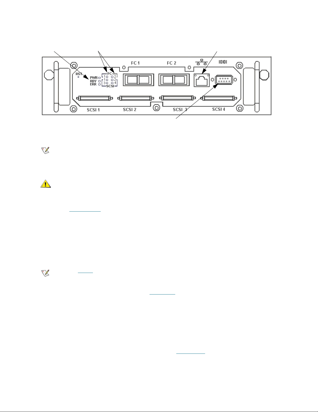
Figure 1 SNC connector and LED panel
Note
CAUTION
Note
RDY LED
FC1 and FC2 connection LEDs
service port
Ethernet port
The placement of the LEDs, SCSI ports, and service port on your SNC may not
be the same as in this example. Refer to the Hardware User’s Guide for your
SNC.
In all of subsequent steps of this procedure, use the name and
number values that your network manager and you have agreed to
use.
2 Issue the hostNameSet
In the example shown, the host name of the SNC was “SN60023”, and it is now being set to “foster.”
The shell prompt will change to reflect the new name.
SN60023 > hostNameSet "foster"
Target hostname set to foster
value = 0 = 0x0
foster >
Step 2 is optional.
3 Configure a static IP address, by issuing the ethAddrSet
The IP address is specified as four decimal numbers, separated by periods.
foster > ethAddrSet "192.168.1.54"
Host Address set to 192.168.1.54 for Ethernet interface
value = 0 = 0x0
If you need to set a netmask, specify it after the network address:
foster > ethAddrSet "10.0.0.2", "255.0.0.0"
If you need a network route and/or default gateway, use gateAddrSet
command to set the SNC name.
command to set the host network address.
to specify it.
foster > gateAddrSet "192.168.1.1"
value = 0 = 0x0
14 Setup and Configuration Routines
Page 21

When more complicated routing is required, use the route command to specify the destination address,
CAUTION
CAUTION
Note
Note
as a full address (single host) or as an abbreviated subnet address.
foster > route "add", "206.0.0", "192.168.1.1"
value = 0 = 0x0
4 If you want to add users, follow the procedure in Creating User Accounts
5 Issue the reboot
command to reboot the SNC:
below, before rebooting.
Using DHCP
Do not use this procedure if you are using an FCB in an intelligent
library ("i" series library, such as Scalar i2000 and Scalar i500) or
Pathlight VX system. Use the appropriate graphical user interface.
An IP address assigned to a device by a Dynamic Host Configuration Protocol (DHCP) server does not
change unless the device is disconnected from the network for a period that exceeds the lease period
defined by the DHCP server. This time period is typically around 3 days. The SNC stores information from
the DHCP server in its boot parameters and attempts to reuse it on subsequent boots in case the DHCP
Server is unreachable.
1 Make sure that a DHCP server is present on the network.
If a DHCP server is unreachable, the SNC Ethernet port will be
unusable.
2 Connect a service terminal to the service port. For the location of this port, see Figure 1
the User’s Guide for your SNC.
on page 14, or
Instructions for connecting a service terminal are included in the User’s Guide
for your SNC.
3 If you’re using FW 4 and an SNC 4000 or 510x, issue the dhcpEnable command.
4 Reboot the SNC for the change to take effect.
5 Connect to the SNC serial port and issue the bootShow command to determine the assigned network
address. Refer to bootShow
You must know the IP address in order to use telnet or the ADIC Management
Console (AMC).
6 If you were referred to this section by another procedure, return to that procedure.
on page 55.
SNC Firmware 4 and 5 Reference Guide 15
Page 22

Setting the Date and Time
CAUTION
Note
Note
Note
Note
Do not use this procedure if you are using an FCB in an intelligent
library ("i" series library, such as Scalar i2000 and Scalar i500) or
Pathlight VX system. Use the appropriate graphical user interface.
The SNC allows you to set the real time clock, to add a timeserver to the system, and to synchronize the
real time clock to the timeserver.
Setting the Real Time Clock
1 Connect a service terminal to the service port. Alternatively, connect a service computer to the network
that the SNC is on or to the Ethernet port of the SNC. For the location of these ports, see Figure 1
page 14, or the User’s Guide for your SNC.
Instructions for connecting a service terminal are included in the User’s Guide
for your SNC.
If you are using Ethernet, open a telnet program to connect to the SNC. Before
you connect by means of telnet, configure a user account. For instructions,
refer to Creating User Accounts
on page 18.
on
2 Use the rtcDateSet command to set the real time clock.
SNC > rtcDateSet 2001,1,26,5,9,30,00
value = 0 = 0x0
SNC >
For detailed information about the parameters taken by the rtcDateSet command, refer to rtcDateSet
[year],[month],[dayofmonth],[dayofweek],[hour],[minute],[second] on page 105.
In the example, the time is set for 9:30 in the morning on January 26, 2001.
Use 24 hour time when programming the real time clock.
Use Greenwich Mean Time.
3 Use the dateSetFromRTC command to set the real time clock on the SNC as the source of date
display. For more information about this command, refer to dateSetFromRTC
SNC > dateSetFromRTC
value = 0 = 0x0
SNC >
4 Use the tzSet command to set the timezone. EST, used in the example, stands for Eastern Standard
Time. For more information about this command, refer to tzSet "timezone"
on page 63:
on page 134.
SNC> tzSet "EST"
TZ Set TIMEZONE = EST:EDT:300:040202:101502
16 Setup and Configuration Routines
Page 23

value = 0 = 0x0
SNC >
Table 2 Valid Timezone Settings
Timezone GMT offset Associated Areas
UTC 0 Greenwich, England
GMT 0 Greenwich Meridian Time
EST GMT -5 Eastern Time (U.S. and Canada), Indiana (East)
CST GMT -6 Central Standard Time (U.S. and Canada
MST GMT -7 Mountain Standard Time
PST GMT -8 Pacific Standard Time (Western U.S. and Canada)
5 Use the date command to confirm. For more information about this command, refer to d
SNC > date
SNC > FRI JAN 26 9:30:49 2001
SNC >
ate on page 63.
Adding a Host System Running Timeserver
1 To enable the timeserver functionality use the setNettime command. For more information about this
command, refer to setNettime [value]
SNC > setNettime 1
Nettime 1 value = 0 = 0x0
SNC >
2 Add a host running timeserver to the SNC using the setTimeHost command. For more information
about this command, refer to setTimeHost "timeserver"
SNC > setTimeHost "butter"
Time Host butter value = 0 = 0x0
SNC >
3 Set the remote system as the source of date/time display using the rdate command. For more
information about this command, refer to rdate "timeserver"
SNC > rdate "butter"
Get time from butter using UDP/SNTP
value = 0 = 0x0
SNC >
on page 115.
on page 116.
on page 103.
4 Use the tzSet command to set the timezone
EST, used in the example, stands for Eastern Standard Time.
SNC > tzSet "EST" TZ Set TIMEZONE = EST:EDT:300:040202:101502
value = 0 = 0x0
SNC >
5 To confirm, use the date command. For more information about this command, refer to d
63.
SNC > date WED JUL 18 14:51:59 2001 value = 0 = 0x0
SNC >
SNC Firmware 4 and 5 Reference Guide 17
ate on page
Page 24

Disabling the Timeserver Host
CAUTION
Note
Note
To disable the timeserver functionality issue the setNettime 0 command.
SNC > setNettime 0
Nettime 0 value = 0 = 0x0
SNC >
The time will revert to the time set on the real time clock on the SNC.
Synchronizing the Real Time Clock with the Timeserver
1 Use the setTimeHost command to add a host running timeserver to the SNC system. For more
information about this command, refer to setTimeHost "timeserver"
SNC > setTimeHost "butter"
Time Host butter value = 0 = 0x0
SNC >
2 Synchronize the real time clock on the SNC with the timeserver using the rtcSetCurrent command.
For more information about this command, refer to r
SNC > rtcSetCurrent
value = 0 = 0x0
SNC >
tcSetCurrent on page 107.
on page 116.
Creating User Accounts
Do not use this procedure if you are using an FCB in an intelligent
library ("i" series library, such as Scalar i2000 and Scalar i500) or
Pathlight VX system. Use the appropriate graphical user interface.
Before you access the SNC using telnet, add a user account.
For inband connections, the default user account name is admin and the
default user account password is password.
To add a user account
1 Connect a service terminal to the service port. For the location of this port, see Figure 1
the User’s Guide for your SNC.
Instructions for connecting a service terminal are included in the User’s Guide
for your SNC.
2 Issue the userAdd command. For more information about this command, refer to the commands
beginning with user in the Service Port Command Reference
on page 41.
on page 14, or
foster > userAdd "username","password"
value = 0 = 0x0
foster >
18 Setup and Configuration Routines
Page 25

Note
The user name you specify must be three or more characters. The password
CAUTION
Note
Note
you specify must be eight or more characters.
Configuring Ports
Do not use this procedure if you are using an FCB in an intelligent
library ("i" series library, such as Scalar i2000 and Scalar i500) or
Pathlight VX system. Use the appropriate graphical user interface.
The settings in Table 3 are the default settings on the SNC:
Table 3 Default SNC Channel Settings
Fibre Channels Public, Target, Loop
Host Type: NT
SCSI Channels Initiator
Termination Enabled
1 Connect a service terminal to the service port. Alternatively, connect a service computer to the network
that the SNC is on or to the Ethernet port of the SNC. For the location of these ports, see Figure 1
page 14, or the User’s Guide for your SNC.
Instructions for connecting a service terminal are included in the User’s Guide
for your SNC.
If you are using Ethernet, open a telnet program to connect to the SNC. Before
you connect by means of telnet, configure a user account. For instructions,
refer to Creating User Accounts
2 Use appropriate firmware commands to accommodate SAN configurations that do not conform to the
default settings. For example, if your system contains few devices that are capable only of arbitrated
loop, the default connection type can be changed to from "loop" to "loop preferred." Refer to Table 4
and Table 5
.
on page 18.
Ready for attaching FCAL
Windows NT or 2000 Hosts
Ready for attaching SCSI
disk or tape devices
on
SNC Firmware 4 and 5 Reference Guide 19
Page 26

Table 4 Fibre Channel Configuration Quick Reference
FC Device Attachment Required Channel Settings Service Port Commands
FC Host type
1
NT (default)
AIX
AS400
setHost [port], “OS”
and
reboot
Autosense/NT
Gateway
Generic
HP-UX
Linux
Netware
Solaris
Unknown
Unisys
FC Switch Point-to-Point
Target (default)
fcConnTypeSet [port],
[connection]
and
fcRestart
FC disk or FC tape
device
Loop (default)
Initiator
2
fcPortModeSet [port],
[mode]
and
fcRestart
1 If eVPS is being used, the FC Host type does not need to be configured manually.
2 The SNCs that use Firmware 4 support 64 initiators per Fibre Channel port
Table 5 SCSI channel configuration quick reference
SCSI Device Attachment
Required Channel
Settings
Service Port Commands
SCSI Host Target scsiHostChanSet
[channel],[mode]
and
reboot
SCSI disk and tape
SCSI Bus shared (dual paths)
SCSI Bus Reset on Power
Up Disabled
scsiResetDisableSet
[channel],[mode]
and
reboot
SCSI disk and tape
SCSI Y-cable (SNC not at
end of SCSI bus)
Termination Disabled scsiTermSet
[channel],[termination]
and
reboot
20 Setup and Configuration Routines
Page 27

Mapping Multiple Paths to Targets
CAUTION
Note
CAUTION
Note
Note
CAUTION
Do not use this procedure if you are using an FCB in an intelligent
library ("i" series library, such as Scalar i2000 and Scalar i500) or
Pathlight VX system. Use the appropriate graphical user interface.
The automatic multi-path mapping (AMP) and manual multi-path mapping (MMP) features allow you to map
alternate paths to the SNC from switch-attached FC devices.
Both automatic and multipath mapping require licensing.
To map multiple Fibre Channel paths to targets
1 Be sure that the devices, the switch, the host, and the SNC have been powered on and have finished
booting. The SNC connects at least two of its Fibre Channel connections to the switch, which connects
to the devices.
These instructions do not take into account zoning software that may
be on the switch.
2 Connect a service terminal to the service port. Alternatively, connect a service computer to the network
that the SNC is on or to the Ethernet port of the SNC. For the location of these ports, see Figure 1
page 14, or the User’s Guide for your SNC.
Instructions for connecting a service terminal are included in the User’s Guide
for your SNC.
If you are using Ethernet, open a telnet program to connect to the SNC. Before
you connect by means of telnet, configure a user account. For instructions,
refer to Creating User Accounts
If you are configuring multiple paths to targets after host connections
have been established, the change in target IDs can damage host
configurations. Optimally, configure multipath mapping as part of
setup.
3 Issue the ampFeatureEnable command. For more information about this command, refer to
mpFeatureEnable “license” on page 53.
a
4 Disconnect SNC Fibre Channel cables from the switch.
5 Clear the map database by issuing the mapWinnowDatabase command. For more information about
this command, refer to mapWinnowDatabase
on page 18.
on page 100.
on
6 Set the multi-path mapping configuration by issuing the mapMultipathSet command.
SNC Firmware 4 and 5 Reference Guide 21
Page 28

Use manual mode (mapMultipathSet 1) when using special host software. Manual mode exposes
CAUTION
CAUTION
all paths to devices, including paths that are hidden because one target device’s World Wide Port Name
is identical to another target device’s World Wide Port Name. Manual mode is used in conjunction with
special host software, so that the user does not inadvertantly identify a single device as two devices,
which can lead to data corruption. Host software allows the user to set one path to the device as primary
and the other as secondary.
SNC > mapMultipathSet 1
Multipath mode set to manual mode.
value = 1 = 0x1
SNC >
Use automatic mode (mapMultipathSet 2) when special host software is not available and all
devices are capable of responding to an inquiry with a unique serial number. Each target drive must
also have two ports, both of which are connected to separate switches. Each switch must be connected
to an SNC FC port. If either switch fails or any cables or GBICs fail on one path, failover automatically
occurs to the other path.
SNC > mapMultipathSet 2
Multipath mode set to automatic mode.
value = 2 = 0x2
SNC >
For more information about this multipath settings, refer to mapMultipathSet
7 Reconnect SNC Fibre Channel cables to the switch.
8 Issue the fcRestart command. For more information about this command, refer to fcRestart [port]
page 73.
9 Issue the mapShowDevs command to confirm that devices have been remapped using the multi-path
configuration that was selected.
If devices have already been mapped, and they need to be remapped,
use the mapRemoveDevice command. Then issue the fcRestart
command.
on page 96.
on
Configuring Channel Zoning
Do not use this procedure if you are using an FCB in an intelligent
library ("i" series library, such as Scalar i2000 and Scalar i500) or
Pathlight VX system. Use the appropriate graphical user interface.
Access between ports configured for host access and ports configured for storage access can be enabled
or disabled as required. The ability to create restricted access on a full-channel basis is called channel
zoning. The default configuration is for all Fibre Channels to have access to all SCSI channels. Channel
zoning is also possible from an FC target channel to an FC initiator channel.
In certain instances, customers may wish to combine the channel level security of channel zoning with the
advanced LUN level security of Scalar Firewall Manager (SFM) to enable a mix of load balancing and host
specific security. In this instance, channel zoning is used to provide load balancing while SFM delivers
resource security and heterogenous host support.
Channel zoning enables load balancing by configuring certain SCSI channels to only be accessible across
specific SAN connections. This is typically done by defining SCSI channels 1 and 2 to be accessible through
FC port 1of the SNC, and SCSI channels 3 and 4 to be to be accessible through FC port 2. This insures that
data traffic is split across the SNC SAN interfaces.
22 Setup and Configuration Routines
Page 29

SFM is configured as usual, but the administrator must be aware that SFM does not override channel
CAUTION
Note
Note
CAUTION
zoning. A host must have LUN level access to a drive through SFM, and be bound to the correct SNC FC
port. If the host is incorrectly connected to the SNC, the combination of channel zoning and SFM may
prevent the host from seeing resources.
While it is possible to configure channel zoning from the command
line by following the procedure specified below, the preferred
interface for channel zoning is the ADIC Management Console (AMC).
For instructions on installing and using AMC, refer to the ADIC
Management Console User Guide.
To configure Channel Zoning
1 Connect a service terminal to the service port. Alternatively, connect a service computer to the network
that the SNC is on or to the Ethernet port of the SNC. For the location of these ports, see Figure 1
on
page 14, or the User’s Guide for your SNC.
Instructions for connecting a service terminal are included in the User’s Guide
for your SNC.
If you are using Ethernet, open a telnet program to connect to the SNC. Before
you connect by means of telnet, configure a user account. For instructions,
refer to Creating User Accounts
on page 18.
2 Issue the setFcChanMask command.
Channel Zoning settings take precedence over settings made by VPS/
SFM, and eVPS.
This command uses bitmasked values to enable or disable access. For a complete discussion of the
formula used to obtain appropriate values, refer to setFcChanMask [channel, bitmask]
Table 6
lists some common values. The examples in Table 6 are all given for Fibre Channel 1, but the
on page 112.
bitmasked values representing SCSI Channel access would not change if Fibre Channel 2 were
specified instead.
Table 6 Common Channel Zoning Configuration Codes
Command String Effect
SNC> setFcChanMask 1,1008 Enables access to SCSI channels 1 - 4 for Fibre
Channel 1
SNC> setFcChanMask 1,1022 Enables access to SCSI channel 1 for Fibre
Channel 1.
SNC> setFcChanMask 1,1021 Enables access to SCSI channel 2 for Fibre
Channel 1.
SNC> setFcChanMask 1,1019 Enables access to SCSI channel 3 for Fibre
Channel 1.
SNC> setFcChanMask 1,1015 Enables access to SCSI channel 4 for Fibre
Channel 1.
SNC> setFcChanMask 1,1020 Enables access to SCSI channels 1-2 for Fibre
Channel 1.
SNC Firmware 4 and 5 Reference Guide 23
Page 30

CAUTION
Note
Note
Note
Table 6 Common Channel Zoning Configuration Codes (Continued)
Command String Effect
SNC> setFcChanMask 1,1011 Enables access to SCSI channels 3-4 for Fibre
Channel 1.
3 After issuing the setFcChanMask command, reboot for the changes to take effect.
Configuring VPM
The VPM (Virtual Private Map) software configures access to specific LUNs for certain SCSI hosts. A
maximum of 256 LUNs per host can be mapped.
While it is possible to configure VPM from the command line by
following the procedure specified below, the preferred interface for
VPM is the ADIC Management Console (AMC). For instructions on
installing and using AMC, refer to the ADIC Management Console
User Guide.
Optionally, before configuring VPM, install the HRS on the hosts involved. Instructions for doing so are in
the User’s Guide for your SNC. It is available for Windows, AIX, HP-UX, Linux, and Solaris hosts.
You must have a license to use VPM.
To configure VPM
1 Connect a service terminal to the service port. Alternatively, connect a service computer to the network
that the SNC is on or to the Ethernet port of the SNC. For the location of these ports, see Figure 1
page 14, or the User’s Guide for your SNC.
Instructions for connecting a service terminal are included in the User’s Guide
for your SNC.
If you are using Ethernet, open a telnet program to connect to the SNC. Before
you connect by means of telnet, configure a user account. For instructions,
refer to Creating User Accounts
2 Issue the vpmFeatureEnable command. For more information about this command, refer to
v
pmFeatureEnable "licensekeystring" on page 140.
3 Issue the targets command. For more information about this command, refer to targets
Take note of the target devices to which you have access. The numbers you need are in the "Idx"
column.
4 Issue the setScsiAssign command. For more information about this command, refer to
setScsiAssign [devID], [channel], [id], [lun]
on page 18.
on page 132.
on page 115.
on
5 Issue the showScsiAssign command.
If results are not as expected, refer to V
6 Reboot the host(s) or use host utilities to rescan available targets.
24 Setup and Configuration Routines
PM MAP on page 187.
Page 31

Configuring eVPS
CAUTION
CAUTION
Note
Note
Note
Do not use this procedure if you are using an FCB in an intelligent
library ("i" series library, such as Scalar i2000 and Scalar i500) or
Pathlight VX system. Use the appropriate graphical user interface.
The eVPS (extended Virtual Private SAN) software configures access to specific LUNs for certain Fibre
Channel hosts. Access to these LUNs can be ordered in different, host-appropriate ways for each host. A
maximum of 256 LUNs per host can be mapped, up to an overall device total of 2048.
While it is possible to configure eVPS from the command line by
following the procedure specified below, the preferred interface for
eVPS is the ADIC Management Console (AMC). For instructions on
installing and using AMC, refer to the ADIC Management Console
User Guide.
Optionally, before configuring eVPS, install HRS on the hosts involved. Instructions for doing so are in the
ADIC Management Console User’s Guide. HRS is available for Windows, AIX, HP-UX, Linux, and Solaris
hosts.
You must have a license to use eVPS.
To configure eVPS
1 Connect a service terminal to the service port. Alternatively, connect a service computer to the network
that the SNC is on or to the Ethernet port of the SNC. For the location of these ports, see Figure 1
page 14, or the User’s Guide for your SNC.
Instructions for connecting a service terminal are included in the User’s Guide
for your SNC.
If you are using Ethernet, open a telnet program to connect to the SNC. Before
you connect by means of telnet, configure a user account. For instructions,
refer to Creating User Accounts
2 Issue the vpsFeatureEnable command. For more information about this command, refer to
vpsFeatureEnable "license key string"
3 Issue the vpsShow command. For more information about this command, refer to vpsShow [hostIndex]
on page 148.
Take note of the host index number. The host index number is the number in the ID column.
4 Issue the targets command. For more information about this command, refer to targets
on page 143.
on page 18.
on page 132.
on
Take note of the target devices to which you have access. The numbers you need are in the "Idx"
column.
5 If you are configuring access to all contiguous LUNs, issue the vpsAccessSet command. For more
information about this command, refer to vpsAccessSet [hostIndex],[Starting lun],[Ending lun],[Access]
on page 141.
SNC Firmware 4 and 5 Reference Guide 25
Page 32

Use the number you noted in Step 3 for the value [hostIndex]. Use the lowest number that was
Note
Note
Note
output by the targets command you issued in Step 4
highest number that was output by the targets command you issued in Step 4
[Ending lun]. Use an access value of "1" to enable access to these LUNs.
If LUNS are not contiguous, use the vpsSparseAccessSet command. For more information about
this command, refer to vpsSparseAccessSet[hostindex],"LUN string",[
6 Issue the vpsAccessApply command.
7 Reboot the host(s) or use host utilities to rescan available targets.
as the value for the [Starting lun]. Use the
as the value for the
access] on page 149.
Using the WWN Lock Mode
The wwnLockModeSet command gives a SAN administrator more direct control over which hosts
(initiators) are able to access the library. SFM/VPS/eVPS must already be enabled for it to be used.
A maximum of 64 initiators can be connected per FC port. If the VPS host table is forced to retain host
entries for initiators that do not have authority to access LUNs available through that SNC, then hosts which
are authorized to access those LUNs may not be able to connect to the SAN. In situations where there are
large numbers of initiators, and SFM/VPS/eVPS has been enabled, the contents of the host table can be
controlled by setting the wwnLockMode to ‘1” (enabled). Then use vpsInitDelete [host ID]
unauthorized hosts and vpsInitAdd
The WWN lock mode default state is disabled.
[hiWWN],[loWWN] to add authorized hosts to the host table.
to remove
1 Connect a service terminal to the service port. Alternatively, connect a service computer to the network
that the SNC is on or to the Ethernet port of the SNC. For the location of these ports, see Figure 1
page 14, or the User’s Guide for your SNC.
Instructions for connecting a service terminal are included in the User’s Guide
for your SNC.
If you are using Ethernet, open a telnet program to connect to the SNC. Before
you connect by means of telnet, configure a user account. For instructions,
refer to Creating User Accounts
2 Before you enable WWN lock mode, check to see if if SFM/VPS/eVPS is enabled. If not, enable it first.
For instructions, refer to sfmFeatureEnable "license key string"
"license key string" on page 143.
3 Issue the wwnLockModeSet command:
SNC > wwnLockModeSet 1
WWN Locking Mode: Enabled
value = 1 = 0x1
SNC >
All hosts whose names are unknown in the VPS host table are deleted.
on page 18.
on page 118 or vpsFeatureEnable
on
The wwnLockMode persists across reboots.
4 Check the state of the WWN lock mode, by issuing the wwnLockModeShow command.
SNC > wwnLockModeShow
WWN Locking Mode: Disabled
26 Setup and Configuration Routines
Page 33

value = 0 = 0x0
Note
CAUTION
Note
Note
Note
SNC >
5 Display a list of hosts that have access to the SNC by issuing the sfmShow command or the vpsShow
command:
SNC > sfmShow
The sfmShow command and the vpsShow command display all the hosts in the VPS host table. For
more information, refer to sfmShow [hostIndex]
Only the hosts in the VPS host table have access to the command and control
LUN when WWN lock mode is enabled.
a. Remove any unwanted hosts from the VPS host table by issuing the vpsInitDel command.
For more information, refer to vpsInitDelete [host ID]
b. Add hosts to the VPS table by issuing the vpsInitAdd command. For more information, refer
to vpsInitAdd
[hiWWN],[loWWN] on page 146.
on page 120.
on page 146.
Configuring Host Port Failover
Do not use this procedure if you are using an FCB in an intelligent
library ("i" series library, such as Scalar i2000 and Scalar i500) or
Pathlight VX system. Use the appropriate graphical user interface.
The host port failover (HPF) feature uses an active/passive methodology. An active (primary) port is used
for host communications, while the passive (standby) port is kept idle. Port failover occurs when connectivity
between the primary port and the SAN ceases to function correctly. This can be caused by a loss of signal
between the ports or excessive errors on the connection. The Fibre Channel ports are connected to the host
computer by means of a switch.
Use automatic or manual multi-pathing (AMP or MMP) to enhance data path
protection for the part of the data path that connects the SNC to devices. Refer
to R
eplacing a SCSI Drive on page 28.
To configure HPF
1 Connect a service terminal to the service port. Alternatively, connect a service computer to the network
that the SNC is on or to the Ethernet port of the SNC. For the location of these ports, see Figure 1
page 14, or the User’s Guide for your SNC.
Instructions for connecting a service terminal are included in the User’s Guide
for your SNC.
If you are using Ethernet, open a telnet program to connect to the SNC. Before
you connect by means of telnet, configure a user account. For instructions,
refer to Creating User Accounts
on page 18.
on
2 Issue the fcConnTypeGet command to make sure the FC ports on the SNC are configured for point
to point.
SNC Firmware 4 and 5 Reference Guide 27
Page 34

If necessary, issue the fcConnTypeSet command to change the setting. For more information about
Note
Note
this command, refer to fcConnTypeSet [port],[connection]
3 Issue the fcPortModeGet command to make sure the FC ports on the SNC are configured as targets.
If necessary, issue the fcPortModeSet command to change the setting. For more information about
this command, refer to fcPortModeSet [port],[mode]
4 Issue the hpfFeatureEnable "licensekey" command. For more information about this command,
refer to hpfFeatureEnable "licensekey"
on page 86.
on page 69.
on page 72.
5 Issue the hpfShow command. For more information about this command, refer to hpfShow
The default configuration will not result in host port failover. Both FC ports on an SNC are active after
HPF is enabled. Each FC port is a virtual port with a standby list consisting entirely of itself. In order for
host port failover to occur, at least one port needs to be on standby list for each active port.
6 Issue the hpfRemovePort command to remove one of the active ports from its own virtual port list. For
example,
SNC > hpfRemovePort 2,2
removes active port 2 from the standby list for virtual port 2.
For another example of the command and its output, refer to hpfRemovePort [virtual port]
on page 88.
7 Issue the hpfAddPort command to add the port that you just removed to the other port’s standby list.
For example,
SNC > hpfAddPort 1,2
adds port 2 to the standby list for virtual port 1.
For another example of the command and its output, refer to h
page 86.
Use hpfShow as needed to monitor the effects of each command.
pfAddPort [virtual port],[phys port] on
on page 89.
,[phys port]
8 Issue the hpfSetErrorRecovery command to set the recovery scenario for ports configured by HPF.
One choice is to have a port return to active status after recovery occurs. Other choices are "return to
standby" which means that the recovered port becomes the new standby port, and "require intervention"
which means that the port stays down until the hpfAddPort command is issued.
For an example of the command and its output, refer to hpfSetErrorRecovery [value]
on page 88.
Replacing a SCSI Drive
When a storage device managed by the SNC is replaced, the device map can be manipulated so that the
host does not require reconfiguration. To do this, set the replacement device’s SCSI target ID to match the
target ID of the removed device.
1 Connect a service terminal to the service port. Alternatively, connect a service computer to the network
that the SNC is on or to the Ethernet port of the SNC. For the location of these ports, see Figure 1
page 14, or the User’s Guide for your SNC.
Instructions for connecting a service terminal are included in the User’s Guide
for your SNC.
28 Setup and Configuration Routines
on
Page 35

Note
If you are using Ethernet, open a telnet program to connect to the SNC. Before
CAUTION
you connect by means of telnet, configure a user account. For instructions,
refer to Creating User Accounts
on page 18.
2 Issue the mapShowDatabase command. Use the listing of the device map that is output to identify the
offline drive.
SN601193 > mapShowDatabase
devId Type Chan tId tLun UID Path
------------------------------------------------------000 SNA 127 127 007f 00000060:451704a9 SINGLE
SN: 601193
001 SCSI 001 006 0000 20100060:451704a9 SINGLE
SN:
002 SCSI 002 002 0000 20200060:451704a9 SINGLE
SN:
003 SCSI 002 001 0000 20300060:451704a9 SINGLE
SN:
value = 0 = 0x0
SN601193 >
If you are not sure which drive is offline, issue the scsiShow command. The scsiShow command lists
all active SCSI drives attached to the SNC. The offline drive is the drive that appears in
mapShowDatabase, but not in scsiShow.
SN601193 > scsiShow
========================================
Ultra2/3 SCSI Initiator Channel 1: 1010 - 0x30c97000 HostId=7 AltId=Auto
ID LUN Vendor Product Rev | Sync/Off Width
--------------------------------------|------------------- 6 0 ADIC Scalar 1000 621A | 10/ 0 8 0/ 0 8
========================================
Ultra2/3 SCSI Initiator Channel 2: 1010 - 0x30cad000 HostId=7 AltId=Auto
No Devices
========================================
Ultra2/3 SCSI Initiator Channel 3: 1010 - 0x30cc3000 HostId=7 AltId=Auto
No Devices
========================================
Ultra2/3 SCSI Initiator Channel 4: 1010 - 0x30cd9000 HostId=3 AltId=6
No Devices
========================================
value = 4 = 0x4
SN601193 >
A comparison of the output of the mapShowdatabase and scsiShow commands makes it clear that
the two drives on SCSI Channel 2 (in the mapShowDatabase output, check the "Chan" column for
devIDs 2 and 3) are not just offline, they are not currently connected at all.
3 Unattach the failed drive from the SNC, if it is not already unattached.
4 Follow the required library procedures to remove and replace the failed drive. For most libraries, the
SCSI ID can be confirmed from the library operator panel. For the Scalar 1000 and the Scalar 10K, set
the pinwheel on the drive itself to correctly configure the SCSI ID.
Make sure that the SCSI Target ID on the replacement drive is the
same as that of the failed drive.
SNC Firmware 4 and 5 Reference Guide 29
Page 36

5 Attach the replacement drive to the same SNC bus as the failed drive.
CAUTION
CAUTION
Note
Note
Do not attach the drive to the SNC SCSI bus before the SCSI ID is set.
6 Reboot the SNC so that the SNC rescans for devices.
7 Issue the mapShowDevs command.
SN601193 > mapShowDevs
devId Type Chan iId iLun UID tId tLun Handle Path
------------------------------------------------------------------------
------000 SNA 127 127 007f 20000060.451704a9 001 000 091bf700h SINGLE
SN: 601193
001 SCSI 001 006 0000 20100060.451704a9 255 255 09ffbc88h SINGLE
SN: ADIC201101595
002 SCSI 002 002 0000 20200060.451704a9 255 255 091b2488h SINGLE
SN: 6811121075
003 SCSI 002 001 0000 20300060.451704a9 255 255 09ffb388h SINGLE
SN: 6811107750
value = 0 = 0x0
SN601193 >
If the replacement drive appears at a different ID than the original devID, make sure that the drive is
attached to the correct SCSI bus and that the drive’s SCSI Target Id (tID) is correct.
Saving a Configuration File
Do not use this procedure if you are using an FCB in an intelligent
library ("i" series library, such as Scalar i2000 and Scalar i500) or
Pathlight VX system. Use the appropriate graphical user interface.
Using HyperTerminal to save the configuration takes much longer than using
the graphical user interface.
It is good practice to save the configuration to a remote system any time it changes.
To save the configuration using a HyperTerminal telnet connection
1 Connect a service computer to the network that the SNC is on or to the Ethernet port of the SNC. For
the location of this port, see Figure 1
Before you connect by means of telnet, configure a user account. For
instructions, refer to Creating User Accounts
2 Follow the manufacturer’s instructions for installing HyperTerminal on the service computer and
opening a session.
on page 14, or the User’s Guide for your SNC.
on page 18.
3 Change the working directory to /nvfs:
cd "/nvfs"
30 Setup and Configuration Routines
Page 37

4 Issue the saveConfig <index> command.
CAUTION
CAUTION
5 From the HyperTerminal window, select Transfer and Receive File.
6 In the Receive dialog box, enter the path to the folder where you want to save the file, or click the
Browse button and navigate to it.
7 For the receiving protocol select Zmodem and press the Close button.
From the HyperTerminal window, enter sz "config.cfg" and press Enter.
The filename "config.cfg" is an example of a name. You can specify a different filename, but it must be
in quotes, it must be eight characters or less, and it must end in .cfg.
To save the configuration to a remote computer connected to the serial port
1 Connect a service computer to the serial port on the SNC. For the location of this port, see Figure 1
page 14, or the User’s Guide for your SNC.
2 Follow the manufacturer’s instructions for installing HyperTerminal on the service computer and
opening a session.
3 cd "/nvfs"
4 From the HyperTerminal window, at the SNC > command prompt, type sz "<filename>.cfg" and then
press the Enter key.
A ZModem session is automatically initiated. It closes automatically when the file transfer has
completed.
on
Updating Firmware
The recommended interface for updating firmware to all SNCs is the
graphical user interface.
Do not interrupt a fimware FTP. If the process is disturbed, damage to
the SNC can result.
As part of ongoing maintenance, firmware can be updated using an Ethernet connection or a telnet
connection.
To update firmware using ftp
1 Connect a service computer to the network that the SNC is on or to the Ethernet port of the SNC. For
the location of ths port, see Figure 1
2 FTP to the SNC (using usual telnet user and password).
C:\>ftp 172.16.77.101
Connected to 172.16.77.101.
220 VxWorks (5.4.2) FTP server ready
User (172.16.77.101:(none)): admin
331 Password required
Password:
230 User logged in
3 Switch to binary mode.
ftp> binary
SNC Firmware 4 and 5 Reference Guide 31
on page 14, or the User’s Guide for your SNC.
Page 38

200 Type set to I, binary mode
Note
CAUTION
4 Upload firmware using "/fwl/fw" as the target.
The character after the "fw" is an "el" (l), not a "one" (1).
ftp> put v042208.bin /fwl/fw
200 Port set okay
150 Opening BINARY mode data connection
226 Transfer complete
ftp: 3542016 bytes sent in 2.74Seconds 1290.82Kbytes/sec.
ftp> quit
C:\>
5 Wait for the Firmware Update Complete status message to be displayed on the service computer
indicating successful completion.
6 Reboot the SNC for the update to take effect.
To update firmware using the serial port
1 Connect a service computer to the serial port on the SNC. For the location of this port, see Figure 1
on
page 14, or the User’s Guide for your SNC.
2 Follow the manufacturer’s instructions for installing HyperTerminal on the service computer and
opening a session.
3 From the HyperTerminal window, at the SNC > command prompt, type rz and then press the Enter key.
4 From the HyperTerminal window select Transfer and Send File.
5 From the Send File dialog enter the path and filename where the firmware file is located or click the
Browse button and navigate to it.
6 In the Protocol field, select Zmodem and click the Send button.
Make sure the serial cable is secure before you begin. Do not disturb
it during the file transfer. If the process is disturbed, damage to the
SNC can result.
The Zmodem file send dialog will display the current status and it will close automatically when the file
transfer has completed.
7 Wait for the Firmware Update Complete status message to be displayed on the service computer
indicating successful completion.
8 Reboot the SNC for the update to take effect. For more information about the reboot command, refer
to reboot
on page 103.
If HyperTerminal reports an error, try to send the file again.
9 Use the exit command to close the telnet session.
32 Setup and Configuration Routines
Page 39

Loading a Configuration File
CAUTION
Note
Note
CAUTION
Do not use this procedure if you are using an FCB in an intelligent
library ("i" series library, such as Scalar i2000 and Scalar i500) or
Pathlight VX system. Use the appropriate graphical user interface.
Using HyperTerminal to upload a configuration file takes much longer than
using the graphical user interface.
A saved configuration can be uploaded as part of recovery from system failure.
To upload a configuration using a HyperTerminal serial connection
1 Connect a service computer to the serial port on the SNC. For the location of this port, see Figure 1
page 14, or the User’s Guide for your SNC.
2 Follow the manufacturer’s instructions for installing HyperTerminal on the service computer and
opening a session.
3 Issue the cd "/fw1/fw" command at the prompt to change the working directory to /fwl/fw.
The character after the "fw" is an "el" (l), not a "one" (1).
4 From the HyperTerminal window, at the command prompt, type rz and then press the Enter key.
5 From the HyperTerminal window select Transfer and Send File.
6 From the Send File dialog enter the path and file name where the configuration file is located or click
the Browse button and navigate to it. In the Protocol field, select Zmodem and click the Send button.
7 Wait for the Configuration Update Complete status message to be displayed on the service computer
indicating successful completion.
8 Issue the restoreConfig <index> command at the Hyperterminal command line.
9 Wait for the Configuration has been cleared. Reboot Required status message to be displayed on the
service computer indicating successful completion.
10 Reboot the SNC for the update to take effect. For more information about the reboot command, refer
to reboot
on page 103.
on
Changing the WWN
Before making any changes to the world wide names of the SNC, read the following discussion in its
entirety.
Do not use this procedure on the SNC 6000 I/O blades in a Pathlight
VX I/O system. The Pathlight VX Storage Processor supplies the
WWN to the SNC 6000 I/O blades.
SNC Firmware 4 and 5 Reference Guide 33
Page 40

All Fibre Channel devices are identified by world wide names (WWNs). These names are used to uniquely
CAUTION
Note
Note
identify a device on a storage area network (SAN) and are used by hosts to correctly connect to the storage
networking controller (SNC) or I/O blade. WWNs are divided into two types: port names, which identify
individual ports, and node names, which identify the entire unit. WWNs are formed of three critical
components:
• Port/Node ID—distinguishes port WWNs from node WWNs
• OUI—identifies the device type, stands for organizational unique identifier
• Device ID—identifies the specific device
Except for the I/O blades in the Pathlight VX, the node ID for Quantum/ADIC devices is always “10:00” and
the port ID is “20:0x” where x is the port number. The OUI is “00:60:45” for the 3000 and 5000 series and
“00:30:8C” for the 6000 and 7000 series. If for any reason you incorrectly enter a WWN, the changes can
be cleared and replaced with the original WWN, which is stored in the SNC.
Only trained and authorized service personnel should use these
procedures. Data corruption or loss may result from the incorrect use
of these procedures. Do not change the WWN of any device on the
SAN before talking to your Quantum-authorized service technician.
Before You Change the WWN on a Replacement SNC
1 Connect a service terminal to the service port. Alternatively, connect a service computer to the network
that the SNC is on or to the Ethernet port of the SNC. For the location of these ports, see Figure 1
page 14, or the User’s Guide for your SNC.
on
Instructions for connecting a service terminal are included in the User’s Guide
for your SNC.
If you are using Ethernet, open a telnet program to connect to the SNC. Before
you connect by means of telnet, configure a user account. For instructions,
refer to Creating User Accounts
2 Locate the saved copy of the current (pre-replacement) configuration.
3 Refer to the output of the fcShowNames command you saved in Step 17
Host SAN or Step 14 of Configuring a SCSI Host SAN. For more information, refer to fcShowNames on
page 76.
4 Install and cable the replacement SNC. For more information, refer to Preparing SAN Components
page 8.
5 Issue the targets command. For more information about this command, refer to targets
If the output of the targets command is not accurate, go to Start MAP
corrections before proceeding with the WWN change.
on page 18.
of Configuring a Fibre Channel
on
on page 132.
on page 167 and make
Changing the WWN for all FC Ports
Use this procedure when you are replacing one SNC with another, and it is critical that the replacement SNC
use the same WWNs as the replaced SNC.
1 Read the section Changing the WW
2 Follow the instructions in Before You Change the WWN on a Replacement SN
34 Setup and Configuration Routines
N on page 33.
C on page 34.
Page 41

CAUTION
The WWN override functions are available only from the service port.
CAUTION
CAUTION
CAUTION
These commands cannot be executed if attempted in a telnet session.
3 Issue the wwnGlobalSet command to establish a new base WWN.
Using the wwnGlobalSet command will update both the node name and port names. For more
information about this command, refer to wwnGlobalSet
The following messages are displayed:
This command will change the WWN for Fibre Channel Ports.
This should only be done when replacing a failed SNC.You should never
operate 2 FC devices that are set to the same WWN. This may destabilize
your SAN.
The unit will be rebooted after the WWN change.
Do you want to proceed (enter "yes" to continue) :
4 Type the word yes and press Enter.
The following message is printed:
Enter the new WWN (or q to quit):
5 Enter all eight bytes of the new WWN. Each byte of the entry should be delimited by colons. For
example, enter:
00:00:00:30:8C:02:70:21
on page 150.
The wwnGlobalSet command requires that the first byte be entered
as "00" even if fcShowNames displays "10" in that position.
When entering the WWN, the firmware will confirm that the node ID
and OUI match the existing values. This prevents a user from
accidentally making the SNC appear as another vendor’s device.
The first five bytes of the entry are checked. If the entry is valid, you are prompted for a password.
6 Type the password OverrideWWN and press Enter.
This causes the SNC to reboot.
7 When the SNC has rebooted, issue the fcShowNames command to verify the change.
Verify that the output in the Node Name column is correct.
8 Continue with the replacement procedure as specified by the User’s Guide for your SNC.
Changing a WWN for one FC port
Use this procedure when you are replacing another vendor’s appliance with an SNC and it is critical that
one of the replacement SNC FC ports use the same WWN as the FC port of the replaced appliance.
Because you are changing the SNC WWNs to represent another
vendor’s device, there are no checks to make sure an appropriate
node or port ID or OUI are entered. Use caution. Entering in
inaccurate WWN information could cause communication issues.
1 Read the section Changing the WW
SNC Firmware 4 and 5 Reference Guide 35
N on page 33.
Page 42

2 Follow the instructions in Before You Change the WWN on a Replacement SNC on page 34.
CAUTION
CAUTION
The WWN override functions are available only from the service port.
These commands cannot be executed if attempted in a telnet session.
3 Issue the wwnPortSet command to set the WWPN and WWNN for a single FC port. For more
information about this command, refer to wwnPortSet [port]
The following messages are displayed:
This command will change the WWN for Fibre Channel Port <N>.
You will be asked to provide both the Node WWN and Port WWN for this port.
You should never operate 2 FC devices that are set to the same WWN. This
may destabilize your SAN.
The unit will be rebooted after the WWN change.
Do you want to proceed (enter "yes" to continue) :
4 Type the word yes and press Enter.
The following message is displayed:
Enter the new Node WWN (or q to quit) :
5 Enter all eight bytes of the new WWNN. The entry should be colon delimited between each byte. For
example, enter:
10:00:00:60:45:02:70:21
on page 152.
The syntax of the entry is checked.
6 If the entry is valid, you are prompted to enter the new WWPN:
Enter the new Port WWN (or q to quit) :
7 Enter all eight bytes of the new WWPN. The entry should be colon delimited between each byte. For
example, enter:
20:01:00:60:45:02:70:21
The syntax of the entry is checked.
Most vendors require the OUI and device ID to match between the
WWPN and WWNN. Make sure these values match or device
connectivity may not occur. It is possible for the SNC to have a
different WWNN for each port.
If the entry is valid, you are prompted for a password.
8 Type the password OverrideWWN and press Enter.
This causes the SNC to reboot.
9 When the SNC has rebooted, issue the fcShowNames command to verify the change.
Verify that the output in the Port Name column is correct.
10 Continue with the replacement procedure as specified by the User’s Guide for your SNC.
Clearing Changes to the WWN for all FC ports
Use this procedure when you are removing an SNC that had its WWNs changed to match a pre-existing unit.
1 Read the section Changing the WW
36 Setup and Configuration Routines
N on page 33.
Page 43

2 Follow the instructions in Before You Change the WWN on a Replacement SNC on page 34.
CAUTION
CAUTION
CAUTION
CAUTION
The WWN override functions are available only from the service port.
These commands cannot be executed if attempted in a telnet session.
The wwnGlobalClear command works only if the wwnGlobalSet
command has been used. To clear port changes made with
wwnPortSet, follow the steps outlined in Clearing Changes to the
WWN for one FC Port on page 37. Then follow this procedure.
3 Issue the wwnGlobalClear command. For more information about this command, refer to
w
wnGlobalClear on page 150.
The following messages are displayed:
This command will restore the WWN for Fibre Channel Ports.
This should only be done when there is no SNC set to this WWN.
You should never operate 2 FC devices that are set to the same WWN. This
may destabilize your SAN.
The unit will be rebooted after the WWN change.
Do you want to proceed (enter "yes" to continue) :
4 Type the word yes and press Enter.
You are prompted for the password.
5 Type the password OverrideWWN and press Enter.
This causes the SNC to reboot.
6 After the SNC has rebooted, issue the fcShowNames command to verify the change.
The output in the Node Name column of the of the fcShowNames command should no longer match
the output saved in Step 17
Host SAN.
of Configuring a Fibre Channel Host SAN or Step 14 of Configuring a SCSI
Clearing Changes to the WWN for one FC Port
Use this procedure when you are removing an SNC that had the WWN on one port changed to match the
WWN of a pre-existing unit.
1 Read the section Changing the WW
2 Follow the instructions in Before You Change the WWN on a Replacement SN
The WWN override functions are available only from the service port.
These commands cannot be executed if attempted in a telnet session.
3 Issue the wwnPortClear <port> command. For more information about this command, refer to
wwnPortClear [port]
on page 151.
N on page 33
C on page 34.
The wwnPortClear command does not reset the port WWN to the
factory default if the wwnGlobalSet command has been used. It
resets the port WWN to the value assigned by the wwnPortSet
command.
The following message will display:
SNC Firmware 4 and 5 Reference Guide 37
Page 44

This command will restore the WWN for Fibre Channel Port <x>. This should
Note
Note
only be done when there is no SNC set to this WWN.
You should never operate 2 FC devices that are set to the same WWN. This
may destabilize your SAN.
The unit will be rebooted after the WWN change.
Do you want to proceed (enter "yes" to continue) :
4 Type the word yes and press Enter.
You are prompted for the password.
5 Type the password OverrideWWN and press Enter.
This causes the SNC to reboot.
6 After the SNC has rebooted, issue the fcShowNames command to verify the change.
7 The output in the Node Name column of the of the fcShowNames command should no longer match
the output saved in Step 17
Host SAN.
of Configuring a Fibre Channel Host SAN or Step 14 of Configuring a SCSI
Retrieving Information About Events
This section contains information about retrieving event logs and Fibre Channel dump information.
Event Log Dump
The events that have been logged in the event log can be displayed. Both normal events and any abnormal
events that may lead you to the source of an internal or external failure are displayed. You can choose to
view only those events logged since the SNC was last booted (loggerDumpCurrent) or you can view a
longer list of events that have accumulated from previous boots (loggerDump).
To view the event log dump
1 Connect a service terminal to the service port. Alternatively, connect a service computer to the network
that the SNC is on or to the Ethernet port of the SNC. For the location of these ports, see Figure 1
page 14, or the User’s Guide for your SNC.
Instructions for connecting a service terminal are included in the User’s Guide
for your SNC.
If you are using Ethernet, open a telnet program to connect to the SNC. Before
you connect by means of telnet, configure a user account. For instructions,
refer to Creating User Accounts
2 Issue one of the following commands:
a. loggerDumpCurrent—to view the events listed since the SNC was last booted
b. loggerDump—to view events that have accumulated from as many previous boots as can be
reported until the limit of 2000 events has been reached
on page 18.
on
Each entry contains a sequence number, day, and time-stamp, the event code, event source (interface
name or system process), an index, and a description of the event.
If the real time clock has been set, the time-stamp will be real time. See also Figure 2
38 Setup and Configuration Routines
.
Page 45

Retrieving the Code 43 Dump File
Note
Note
CAUTION
Event code 43 is recorded in the SNC event log along with the name of a file that was saved to the flash file
system. That file contains information about the state of the Fibre Channel interface prior to the reset.
If an event code 43 was reported to the ADIC Management Console client, it is an indication that the SNC
performed an error recovery operation and had to reset the Fibre Channel interface to clear a lock-up
condition.
To retrieve the code 43 dump file
1 Connect a service terminal to the service port. Alternatively, connect a service computer to the network
that the SNC is on or to the Ethernet port of the SNC. For the location of these ports, see Figure 1
page 14, or the User’s Guide for your SNC.
Instructions for connecting a service terminal are included in the User’s Guide
for your SNC.
If you are using Ethernet, open a telnet program to connect to the SNC. Before
you connect by means of telnet, configure a user account. For instructions,
refer to Creating User Accounts
2 Navigate to the DUMP directory by entering the cd “/ffs/dump” command.
on page 18.
on
3 Issue the ls command to get a file listing for the directory.
There may be more than one file present if the error condition has occurred more than once.
Dump file names end in .dmp. Existing dump files can be overwritten
by newer dump files.
4 Refer to the section S
Substitute the name of the dump file and use that procedure to save the file to the service computer.
Repeat this step if there is more than one file.
Save each file to the service computer.
5 Send the file to technical support for analysis, attaching the dump files to the message.
aving a Configuration File on page 30.
Working With Command Flow Log Information
Two kinds of events are recorded in the command flow log file: sequence events and single command
events. Sequence events are Read/Write commands. All other events are single command events. Several
commands can be used to produce command flow log information:
• cfLogTimePlayback
• cfLogTimePlaybackAll
• cfLogEventPlayback
• cfLogEventPlaybackAll
Use these commands to get command flow log information limited by a particular LUN, time period, or a
specified number of events.
SNC Firmware 4 and 5 Reference Guide 39
Page 46

The output that results from these commands starts with the internal LUN number of the device for which
information is being provided. The device’s vendor, product ID, and serial number are also listed in this line:
LUN=1 Vendor=HP Product=Ultrium 1-SCSI SN=IE71K05450
After this line, numbered events pertaining to the cited LUN are printed. Each line begins with an event
number. In the following example, the event number is 506:
000000506 MAY27 08:17:12 2 125 WRITE=021540 ERR=000000 08:28:45
The event number is followed by the month, day of the month, start time, initiator channel and initiator index.
In event 506, the word "Write" after the initiator index indicates that the sequence event "Write" is being
logged. The number "021540" after "Write" represents the number of times the SNC carried out the "Write"
command. No errors were recorded in the course of the command being carried out. Compare the time
stamp at the end of this line to the start time to determine how long it took the SNC to complete the sequence
event.
If data was transferred to or from the host, a new line is displayed indicating the direction of the transfer
("DIR=IN" is to the host and "DIR=OUT" is from the host), the number of bytes requested (REQ) and the
number of bytes actually transferred (XFER):
DIR=IN REQ=14 XFER=14
If the event is a single command event, as in event 511 below, the initiator index is followed by an 8
character abbreviation for the operation code, the command descriptor block—which may be 6, 10, 12 or
16 bytes in length—the command completion status, and end time:
000000511 MAY27 08:28:51 2 125 MODE SNS 1a0000000c00 GOOD(00) 08:28:51
Refer to a SCSI command reference guide to understand the operation code and command descriptor block
information.
Whenever the command completion status is not good (check condition 02), the 18 byte sense data is also
displayed, as in event 739 below.
000000739 MAY27 08:37:38 2 125 LOG SNS 4d002e00000000040000 CHCK(02)08:37:38
DIR=IN REQ=400 XFER=00
DEV-SENSE=70 00 05 00 00 00 00 0a 00 00 00 00 24 00 00 cf 00 02
Illegal Request: Invalid Field in CDB
The status origin is shown as DEV if the status is from the device and SNC if the SNC returned the status.
The sense data fields for Filemark, EOM, ILI, key, additional sense code, and additional sense code qualifier
are translated and displayed on the next line. Refer to a SCSI command reference guide to understand the
the sense data in these fields.
40 Setup and Configuration Routines
Page 47

Service Port Command Reference
A “shell” interface provides access to the management and configuration commands referenced in this
chapter. Connect a terminal or a computer with terminal emulation software to the service port to access
the shell. Instructions for doing so are contained in the User’s Guide for your SNC.
Managing the SNC
The ADIC Management Console application (AMC) is the preferred method for managing the SNC. When
you use AMC, the operations described in this guide are carried out by means of a graphical user interface.
For installation and use, refer to the ADIC Management Console User’s Guide. Not all the commands listed
in this section are available in AMC.
Commands
This section specifies the commands that are available to control, manage, and service the SNC. Each
command description provides procedural information as well as an example of the screen display. The
actual screen display may vary, depending on your SNC and Library version and configuration.
The commands, organized by function, are provided in Table 7
the table, starting with adicNvLogDump
Command Reference on page 155 and Troubleshooting on page 161.
Some commands are only available for Firmware 4 or for Firmware 5, but not both. The page listings in the
FW4 and FW5 columns of Table 7
Each command outputs a status “value” in decimal and hexadecimal after execution and before a new
prompt is displayed.
value = 0 = 0x0
Usually a value of 0 indicates success, but some successful commands return a different value.
Table 7 Service port commands listed alphabetically by functional group
Command or Command
Group
disableCC Disable command and control interface 65
enableCC Enable command and control interface 66 66
SNC Firmware 4 and 5 Reference Guide 41
on page 53. The commands are also used in the Diagnostic
indicate which commands are available for FW4, FW5, or both.
Description
and alphabetically immediately following
FW4
desc
FW5
desc
65
Page 48

Table 7 Service port commands listed alphabetically by functional group (Continued)
Command or Command
Group
Description
FW4
desc
FW5
desc
setSnaCCLun Change command and control interface LUN 116 116
Channel Zoning
setFcChanMask Configure fibre channel zoning 112
112
Data Mover
sncFeatureEnable Enable the optional Data Mover feature 123
Data Path Conditioning
ghostIOSet Change the length of time that commands to FC
Refer also to Host Port Failover and Health
Check
80
123
80
targets remain queued
ampFeatureEnable Enable the optional multi-path mapping feature 53 53
ghostIOShow Display the length of time that commands to FC
80 80
targets remain queued
mapMultipathSet Change the setting for mapping new targets 96 96
mapMultipathShow Display the current setting for mapping new targets 97 97
mapRemoveDevice Remove a device from the persistent device map 98 98
tpathShow Display the state of targets mapped for failover 133 133
Diagnostics
bootShow Display the boot parameters 55
diagBoot Transition an SNC from normal operations to
Diagnostic commands are located in Diagnostic
Command Reference on page 155.
55
156 NA
diagnostic mode
elTest Perform an Ethernet loop back test 156
fcSlotTest Perform a confidence test on a fibre channel slot 157
normalBoot Transition an SNC from diagnostic mode to normal
158
NA
NA
NA
operations
scsiChannelTest Perform a confidence test on a pair of SCSI
158
NA
channels
showBox Display components of the SNC 159
supportDump Output the result of a number of service port
125
NA
125
commands in a standard way and in a specific
order.
Environmental Sensors
envMonShow Display all environmental states 67
envMonRangeShow Display the allowable ranges for environmental
67 67
67
states
42 Service Port Command Reference
Page 49

Table 7 Service port commands listed alphabetically by functional group (Continued)
Command or Command
Group
Description
fanShow Display fan blade controller, EEPROM, and
FW4
desc
FW5
desc
68 68
temperature sensor information
Ethernet Network
arptabShow Display a list of known ARP entries 53
53
dhcpClientShow Display data received from the DHCP server NA 64
ethAddrGet Display Ethernet port address 67 67
ethAddrSet Set Ethernet port address 68 68
gateAddrGet Display network gateway address 79 79
gateAddrSet Set network gateway address 79 79
host “add” Add host table entries 83 83
host “delete” Delete network host table entries 84 84
host “list” List network host table entries 85 85
hostNameGet DIsplay the network name of the SNC. 85 85
hostNameSet Change network name 85 85
hostTypeShow Display the host type setting for each fibre channel. 86 86
icmpstatShow Display statistics for ICMP 91 NA
ifShow Display Ethernet port parameters and status 91
91
inetstatShow Display all Internet protocol sockets 92 92
ipstatShow Display statistics for IP 93 93
macShow Display Ethernet port media access control address 95 95
mbufShow Display mbuf statistics 101 101
route Edit route table entries 104 104
route “add” Add network route table entries 105 105
route “delete” Delete network route table entries 105 105
route “list” List network route table entries 105 105
snmpCommunitiesShow Display list of Community names currently in use 123 123
snmpReadCommunityAdd Add Community name with Read permission 124 124
snmpReadCommunityRemove Remove Community name Read permission 125 125
snmpTrapCommunitySet Set Community name passed with traps 124 124
snmpWriteCommunityAdd Add Community name with write permission 124 124
snmpWriteCommunityRemove Remove Community name write permission 125 125
SNC Firmware 4 and 5 Reference Guide 43
Page 50

Table 7 Service port commands listed alphabetically by functional group (Continued)
Command or Command
Group
Description
FW4
desc
FW5
desc
tcpstatShow Display statistics for TCP 133 133
trapDestAdd Add recipient IP address to trap destination table 134 134
trapDestRemove Remove recipient IP address from trap destination
134 134
table
trapDestShow Display trap destination table 134 134
udpstatShow Display statistics for UDP 135 NA
userAdd Add a user and password to the password file 136
136
userDelete Delete a user from the password file 136 136
userList Display the contents of the password file 136 136
Event Logging
cfLogHelp Display a list of the commands used to work with
55
55
command flow log information
cfLogDetailDisable Disable detailed command flow logging 56 56
cfLog DetailEnable Enable detailed command flow logging 56 56
cfLogTimePlayback Display command flow log events for a specified
56 56
time period for a specified device
cfLogDetailShow Display the current detail trace mode setting 56 56
cfLogTimePlaybackAll Display command flow log events for a specified
57 57
time period for all devices
cfLogEventPlayback Display a specified number of command flow log
56 56
events for a specified device
cfLogEventPlaybackAll Display a specified number of command flow log
57 57
events for all devices
cflSnap Create a snapshot of the specified LUN’s CFL 58 58
cflSnapAll Create a snapshot of all LUN’s CFL 58 58
cflSnapHelp Displays a list of commands used to work with CFL
57 57
snapshot
cflSnapShow Displays CFL size information. 58 58
cflSnapSizeGet Returns the total number of bytes required to save
59 59
CFL for specified LUN.
cflSnapAllSizeGet Returns the total number of bytes required to save
58 58
all CFLs.
csClearLogFile Clear the event log 60 60
csDisableDisplay Disables debug display to STDOUT NA 60
csEnableDisplay Enables debug display to STDOUT NA 60
44 Service Port Command Reference
Page 51

Table 7 Service port commands listed alphabetically by functional group (Continued)
Command or Command
Group
Description
FW4
desc
FW5
desc
csEnhancedDisplay Enables or disables STDOUT display enhancement NA 60
csLogHelp Displays a list of the commands used to work with
NA 60
debug and event logging
csSetDisplayLevel Sets current debug display level NA 61
csSetDisplayLevelDefault Sets current debug display level to default value NA 61
csSetLogLevel Sets current debug log level NA 62
csSetLogLevelDefault Sets current debug log level to default value NA 62
csShowDisplayLevel Displays current debug display level NA 62
csShowLevels Displays flag value for each subfunction NA 62
csShowLogLevel Displays current debug log level NA 63
loggerDump Display event log records 93 93
loggerDumpCurrent Display event log records for current boot 94 94
supportDump Display information used in troubleshooting 125 125
eVPS
Refer to SAN Access Security: Extended VPS
(eVPS)
Fibre Channel
fcChipInfoShow Display manufacturer information for Fibre Channel
69
NA
device
fcConnTypeGet Display the current setting of a fibre channel port’s
69
69
connection type
fcConnTypeSet Set the type of connection for a fibre channel port 69 69
fcFibreSpeedGet Display maximum and current speeds of fibre
70 70
channel port
fcFibreSpeedSet Set fibre channel port speed 70 70
fcGbicShow Display the GBIC information for each installed
71 71
GBIC
fcPortModeGet Display the mode for the specified fibre channel port 72 72
fcPortModeSet Set the mode for the specified fibre channel port 72 72
fcRestart Restart the specified fibre channel port 73 73
fcShow Display fibre channel interface status 73 73
fcShowDevs Display attached SCSI and fibre channel target
75 75
devices from fibre channel port perspective
fcShowNames Display node and port names for fibre channels 76 76
fcShowRegs Display register data for Fibre Channel device 77 77
SNC Firmware 4 and 5 Reference Guide 45
Page 52

Table 7 Service port commands listed alphabetically by functional group (Continued)
Command or Command
Group
Description
FW4
desc
FW5
desc
fcTransceiverShow Display the SFP information for each installed SFP 78 78
fcTxDisable Disable a fibre channel port transmitter 79 79
fcTxEnable Enable or re-enable a fibre channel port transmitter 79 79
setFcFrameSize Set frame size for specific fibre channel port 113 113
setFcHardId Set loop ID for specific fibre channel port 114 114
setHost Set host OS type for specific fibre channel port 114 114
sysNodeNameModeSet Change the fibre channel node name mode 127 127
sysNodeNameModeShow Display the current fibre channel node name mode 128 128
targets Display attached SCSI and fibre channel target
132 132
devices
Flash File System
cd Set current working path 55
55
ll List directory contents in long format 94 94
ls List directory contents 94 94
rm Remove (delete) a file 104 104
rz Initiate a receive Zmodem file transfer session 107 107
sz Initiate a send Zmodem file transfer session 132 132
Health Check
hlthChkIntervalGet Display health check interval 82
82
hlthChkIntervalSet Set health check interval 82 82
hlthChkLevelGet Display health check level 83 83
hlthChkLevelSet Set health check level 83 83
hlthChkNow Perform a health check now 83 83
Help
cfLogHelp Displays a list of the commands used to configure
55
55
command flow logging or display command flow log
information
csLogHelp Displays a list of the commands used to work with
NA 60
debug and event logging
diagHelp Display diagnostic command info 65 NA
help Display info for all shell commands 81
81
hlthChkhelp Display health check command info 82 82
46 Service Port Command Reference
Page 53

Table 7 Service port commands listed alphabetically by functional group (Continued)
Command or Command
Group
Description
FW4
desc
FW5
desc
mapHelp Display device map command info 96 96
netHelp Display network command info 101 101
snmpHelp Display SNMP command info 123 123
userHelp Display user account command info 136 136
Host Port Failover
hpfAddPort Add a physical port to the stand by list for a virtual
86
86
port
hpfDisplayLinkDownDelay Display the length of the delay after link down status
86 86
has occurred before host port failover occurs
hpfFeatureEnable Enable the optional host port failover feature 86 86
hpfFeatureDisable Disable the optional host port failover feature 87 87
hpfMakeActive Make a given physical port the active channel for a
87 87
given virtual port
hpfMakePrimary Make a given physical port the active channel for a
87 87
given virtual port
hpfPortEnable Re-enable a recovering port that is configured to
88 88
require intervention after failure
hpfRemovePort Remove a physical port from a virtual port's standby
88 88
port list
hpfSetErrorRecovery Set the recovery scenario for a port, when the
88 88
failure of a port is due to error count
hpfSetLinkDownDelay Set the amount of time a port’s link is down before
89 89
failover occurs
hpfSetLinkDownRecovery Set the recovery scenario for a port, when the
89 89
failure of a port is due to link down
hpfShow Display current host port failure state and
89 89
configuration
hpfShowErrorRecovery Display the recovery scenario settings 90 90
Multipath Mapping Refer to Data Path Conditioning
Product Data and
Maintenance
adicNvLogDump Dump exception handling data 53
53
clearReservation Force-clear a reservation on the specified target
59 59
LUN
SNC Firmware 4 and 5 Reference Guide 47
Page 54

Table 7 Service port commands listed alphabetically by functional group (Continued)
Command or Command
Group
Description
initializeBox Restore factory defaults by deleting all configuration
FW4
desc
FW5
desc
92 92
files including persistent address map and private
maps, and then reboot
licenseShow Display information about installed software license
93 93
keys
mapCompressDatabase Remove inactive device entries and reassign LUNS
95 95
contiguously in persistent address map database
mapRebuildDatabase Delete and reconstruct persistent address map
97 97
database
mapShowDatabase Display all persistent address map database entries 98 98
mapShowDevs Display persistent address map database entries
99 99
for attached devices only
mapWinnowDatabase Remove inactive device entries from persistent
100 100
address map database
mapWinnowDatabaseLun Remove specified device entry from persistent
100 100
address map database
pipVpdShow Display vital product data for the power and
102 102
identification processor
reserveShow Output a list of devices with reservations. 103 103
restoreConfig Restore a previously saved configuration file 104 104
ridTag Display and set serial number of replaced base 104 104
saveConfig Save a configuration file 107 107
shellLock Lock or unlock the shell command interface 121 121
showBox Display graphic of hardware 159 NA
showProductType Displays the current product type the firmware is
121
121
running
showVersions Displays the version of the operational firmware,
122 122
Power-On-Self-Test (POST), bootrom and alternate
bootrom
sysConfigShow Display configuration settings 127 127
sysVpdShow Display vital product data 127 127
sysVpdShowAll Display vital product data for all subsystems 127 127
uptime Display time elapsed since last boot 135 135
version Display firmware version 136 136
vipGetUMFirmwareVersion Display version number of functional firmware on
137 137
utility module
48 Service Port Command Reference
Page 55

Table 7 Service port commands listed alphabetically by functional group (Continued)
Command or Command
Group
Description
FW4
desc
FW5
desc
vipSendPIPFirmware Send PIP firmware to the specified I/O blade 137 137
vipSendPIPFirmwareAll Send PIP firmware to the both I/O blades 137 137
vipSendUMFirmware Send functional firmware to the specified utility
138 138
module
vipSendUMFwloader Send bootloader firmware to the specified utility
139 139
module
wd_dataDump Dump watchdog data 150 150
wwnGlobalClear Restore the node WWN to the factory setting 150 150
wwnGlobalSet Set the node WWN for FC ports 150 150
wwnPortClear Restore the port WWN to the factory settings 151 151
wwnPortSet Set the Port WWN for an FC port 152 152
For commands used with extended VPS (eVPS),
refer to SAN Access Security:
Extended VPS (eVPS).
SAN Access Security:
Scalar Firewall Manager
(SFM)
All commands beginning "sfm" can be
interchanged for commands beginning with "vps."
Not all commands beginning with "vps" have "sfm"
equivalents.
sfmAccessApply Apply access settings and save in SFM database 116
116
sfmAccessClear Disable SFM access to all LUNs for all hosts 116 116
sfmAccessSet Set SFM access permission for a specific host and
117 117
a specific LUN range
sfmActiveSet Reactivate SFM if inactive 117 117
sfmConnectionSet Enter connection information for a specific SFM
117 117
host
sfmFeatureDisable Disable SFM 117 117
sfmFeatureEnable Enable SFM with license key 118 118
sfmFileShow Show the SFM data stored in the file 118 118
sfmHostShow Display LUN access permissions for a specific SFM
118 118
host
sfmInactiveSet Deactivate SFM access control allowing all hosts to
119 119
access all LUNs
sfmNameSet Enter a name for a specific SFM host 120 120
SNC Firmware 4 and 5 Reference Guide 49
Page 56

Table 7 Service port commands listed alphabetically by functional group (Continued)
Command or Command
Group
Description
sfmShow Display status information for one or all registered
FW4
desc
FW5
desc
120 120
SFM hosts
sfmSparseAccessSet Set access permission for a specific SFM host and
120 120
specific LUNs
sfmTypeSet Enter operating system information for a specific
121 121
SFM host
wwnLockModeSet Enable or disable the removal of unknown hosts
151 151
from VPS host table
wwnLockModeShow Display the WWN lock mode setting 151 151
For commands used with Scalar Firewall
Manager (SFM), refer to SAN Access Security:
Scalar Firewall Manager (SFM)
SAN Access Security:
Extended VPS (eVPS)
All commands beginning "sfm" can be
interchanged for commands beginning with "vps."
Not all commands beginning with "vps" have "sfm"
equivalents
vpsAccessApply Apply access settings and save in VPS or eVPS
140
140
database
vpsAccessClear Disable eVPS access to all LUNs for all hosts 141 141
vpsAccessSet Set eVPS access permission for a specific host and
141 141
a specific LUN range
vpsActiveSet Reactivate VPS or eVPS if inactive 141 141
vpsConnectionSet Enter connection information for a specific VPS or
141 141
eVPS host
vpsDefaultInbandAccessGet Display in-band access settings for the SNC 142 142
vpsDefaultInbandAccessSet Set in-band access levels for the SNC 142 142
vpsFeatureDisable Disable VPS and eVPS 143 143
vpsFeatureEnable Enable VPS and eVPS 143 143
vpsFileFlush Save settings into the SFM/VPS/eVPS database 143 143
vpsFileShow Show the VPS or eVPS data stored in the file 143 143
vpsHostInbandAccessGet Display in-band access settings for a particular
144 144
eVPS host
vpsHostInbandAccessSet Set the in-band access level for a single eVPS host 144 144
vpsHostShow Display LUN access permissions for a specific VPS
145 145
or eVPS host
50 Service Port Command Reference
Page 57

Table 7 Service port commands listed alphabetically by functional group (Continued)
Command or Command
Group
Description
FW4
desc
FW5
desc
vpsInactiveSet Deactivate VPS or eVPS if active 146 146
vpsInitAdd Add a host to the SFM/VPS/eVPS database 146 146
vpsInitDelete Remove a host from the SFM/VPS/eVPS database 146 146
vpsInitOffline Take an SFM/VPS/eVPS host offline 146 146
vpsMapAdd Assign a target device to an eVPS host 147 147
vpsMapClear Clear all the mapping assignments for a specified
147 147
eVPS host
vpsMapDelete Delete a previous eVPS LUN assignment 147 147
vpsMapShow List all available mapping information for an eVPS
148 148
host
vpsNameSet Enter a name for a specific VPS or eVPS host 148 148
vpsShow Display status information for one or all registered
148 148
VPS or eVPS hosts
vpsSparseAccessSet Set access permission for a specific VPS or eVPS
149 149
host and specific LUNs
vpsTypeSet Enter operating system information for a specific
149 149
VPS or eVPS host
vpsWwnSet Remove a host from the SFM/VPS/eVPS database 149 149
wwnLockModeSet Enable or disable the removal of unknown hosts
151 151
from VPS host table
wwnLockModeShow Display the WWN lock mode setting 151 151
fcShowDevs Display SCSI and fibre channel Target Devices from
75 75
fibre channel port perspective
getScsiScanTime Display the length of time that the SCSI bus is
80 NA
rescanned after boot completes
setScsiScanTime Set the length of time that the SCSI bus is
116
NA
rescanned after boot completes
scsiAltIdGet Display SCSI alternate IDs 108
scsiAltIdSet Change SCSI alternate IDs 108
scsiHostChanGet Display SCSI host channel modes 108
scsiHostChanSet Set SCSI host channel modes 109
scsiHostIdGet Display SCSI host ID numbers 109
NA
NA
NA
NA
NA
scsiHostIdSet Set SCSI host ID numbers 109
scsiRescan Rescan for devices on one or all SCSI channels 110
scsiResetDisableGet Display SCSI Bus Reset on Power-Up Setting 110
SNC Firmware 4 and 5 Reference Guide 51
NA
NA
NA
Page 58

Table 7 Service port commands listed alphabetically by functional group (Continued)
Command or Command
Group
Description
FW4
desc
FW5
desc
scsiResetDisableSet Set the SCSI Bus Reset on Power-Up Setting 111 NA
scsiShow Display SCSI channels and attached devices 111
scsiTermGet Display termination status information for SCSI
112
NA
NA
channels
scsiTermSet Set termination status for the selected channel 112
snReset Restart a SCSI channel 125
targets Display attached SCSI and fibre channel Target
132
NA
NA
132
devices
Startup
diagBoot Shutdown and restart in Diagnostic mode 156
normalBoot Shutdown and restart in Normal mode 158
reset Restart without shutdown 104
NA
NA
104
reboot Shutdown and restart 103 103
Time and Date
date Display the date and time 63
63
dateSetFromRTC Set the real time clock as the source of date display 63 63
hostShow Display the IP address of the system timeserver 85 85
rdate Set a remote system as the source of date display 103 103
rtcDateSet Manually set the real time clock 105 105
rtcGet Display the real time clock setting 106 106
rtcSetCurrent Synchronize the real time clock with the timeserver 107 107
setNettime Enable or disable timeserver functionality 115 115
setTimeHost Add a host running timeserver to the system 116 116
tzSet Set the time zone offset from Greenwich Mean Time 134 134
Virtual Private Map
copyScsiAssign
deleteScsiAssign
setScsiAssign
Copy SCSI assignments from a source channel to a
destination channel
Delete an assignment previously created
Assign a target device to a SCSI channel
59
63
115
NA
NA
NA
showScsiAssign
vpmFeatureEnable
52 Service Port Command Reference
List the current assigned addresses for the indicated
channel
Enable the optional Virtual Private Map feature
122
140 140
NA
Page 59

Table 7 Service port commands listed alphabetically by functional group (Continued)
Command or Command
Group
vpmFeatureEnabled
Description
Display status information about Virtual Private Map
FW4
desc
140 140
FW5
desc
adicNvLogDump
The adicNvLogDump command dumps the exception handling data. This is an example from an SNC
7404, FW 5.
SNC > adicNvLogDump
****** INTERRUPT EXCEPTION LOG ******
Vector ProgCntr
0x00000300 0x00112a34 <-- newest
value = 1 = 0x1
SNC >
ampFeatureEnable “license”
The ampFeatureEnable command enables the optional multipath mapping feature. You enable the feature
by entering the unique license key.
SNC > ampFeatureEnable "N499F-ZZ"
Copy OK: 60 bytes copied
AMP Enabled, License is Valid
value = 0 = 0x0
SNC >
If the license key was factory-installed, you can enter the word “enable” (in quotes) rather than the actual
license key.
SNC > ampFeatureEnable "enable"
AMP Enabled, License is Valid
value = 0 = 0x0
SNC >
If value = 1 = 0x1 message is displayed, it means the license is already installed and multi-path
mapping is already enabled.
If the value = -1 = 0xffffffff message is displayed, it means the license is not already installed
and you do need to enter the license key.
arptabShow
The arptabShow command displays the contents of the ARP table. The ARP table contains the current
Internet-to-Ethernet address mappings. This information can be useful to the LAN administrator.
SNC > arptabShow
LINK LEVEL ARP TABLE
destination gateway flags Refcnt Use Interface
----------------------------------------------------------------
172.16.77.1 00:e0:16:92:91:86 405 1 0 emac0
172.16.77.21 00:d0:59:cf:f3:d1 405 1 28 emac0
172.16.77.50 08:00:09:fd:63:c6 405 1 32 emac0
----------------------------------------------------------------
SNC Firmware 4 and 5 Reference Guide 53
Page 60

value = 75 = 0x4b = 'K'
SNC >
54 Service Port Command Reference
Page 61

bootShow
The bootShow command displays information about the bootfile and profile used at the last boot.
SNC4 > bootShow
boot device : ibmEmac
unit number : 0
processor number : 0
host name : host
file name : //ffs/vxWorks.st
inet on ethernet (e) : 172.16.76.253:ffffff00
gateway inet (g) : 172.16.76.1
flags (f) : 0x8
target name (tn) : SNC4K
startup script (s) : //ffs/sna.rc
value = 0 = 0x0
SNC>
cd
You can move to a different directory (usually in the flash file system) using the cd command.
SNC > cd "MGMT"
value = 0 = 0x0
SNC >
cfLogHelp
The cfLogHelp command displays a list of the commands used to configure command flow logging or
display command flow log information.
SNC601112 > cfLogHelp
CFL - Command Flow Logging event facility
cfLogDetailDisable - (default) Disables detailed command flow logging. All
command events will be logged as single command events and sequence
command events.
cfLogDetailEnable - Enables detailed command flow logging. All command
events will be logged as single command events.
cfLogDetailShow - Display the current detail trace mode setting.
cfLogTimePlayback <LUN>,<minutes> - Displays a single LUN's command flow
log events for the specified number of minutes (0-4320). If minutes not
specified orZERO, then ALL log entries displayed.
cfLogEventPlayback <LUN>,<events> - Displays a single LUN's command flow
log entries for the specified number of events (0-4096). If events not
specified or ZERO, then ALL log entries displayed.
cfLogEventPlaybackAll <events> - Displays command flow log events for ALL
LUN’s for the specified number of events (0-4096). If events not
specified or ZERO, then ALL log entries displayed.
cfLogTimePlaybackAll <minutes> - Displays command flow log events for all
LUN’s for the specified number of minutes (0-4320). If minutes not
specified or ZERO, then ALL log entries displayed.
value = 0 = 0x0
SNC601112 >
SNC Firmware 4 and 5 Reference Guide 55
Page 62

cfLogDetailDisable
Note
The cfLogDetailDisable command disables detailed logging if detailed command flow logging had
been previously enabled. The default setting for command flow logging is disabled. Logged commands are
classified as "sequence events" or "single events."
When the command flow log is disabled, Read and Write commands are the only commands that are logged
as sequence command events. Multiple Read or Write commands result in one sequence event log entry.
All other commands are logged as single command events.
SNC601112 > cfLogDetailDisable
Command Flow Log Details are:DISABLED
value = 0 = 0x0
SNC601112 >
cfLogDetailEnable
The cfLogDetailEnable command enables detailed command flow logging. All command events are
logged as single command events.
SNC601112 > cfLogDetailEnable
Command Flow Log Details are:ENABLED
value = 0 = 0x0
SNC601112 >
cfLogDetailShow
The cfLogDetailShow command displays the current detail trace mode setting.
SNC601112 > cfLogDetailShow
Command Flow Log Details are:ENABLED
value = 0 = 0x0
SNC601112 >
cfLogEventPlayback [LUN],[events]
The cfLogEventPlayback command displays a specified number of command flow log events for a
specified LUN.
Command flow events for disk devices are not logged.
Enter the number of playback events from 0-4096 to limit the number of events displayed. If the number of
events is not specified or is "0", all events for the LUN will be displayed.
SNC601112 > cfLogEventPlayback 1,10
LUN=1 Vendor=HP Product=Ultrium 1-SCSI SN=IE71K05450
000000497 MAY27 08:16:54 2 125 RDBLKLMT 050000000000 GOOD(00) 08:16:54
DIR=IN REQ=06 XFER=06
000000498 MAY27 08:16:54 2 125 TUR 000000000000 GOOD(00) 08:16:54
000000499 MAY27 08:16:54 2 125 READ POS 34000000000000000000 GOOD(00) 08:16:54
DIR=IN REQ=14 XFER=14
000000500 MAY27 08:16:54 2 125 WRITE=000001 ERR=000000 08:16:54
000000501 MAY27 08:16:54 2 125 WRITE FM 100000000100 GOOD(00) 08:16:55
000000502 MAY27 08:16:55 2 125 TUR 000000000000 GOOD(00) 08:16:55
000000503 MAY27 08:16:55 2 125 READ POS 34000000000000000000 GOOD(00) 08:16:58
DIR=IN REQ=14 XFER=14
000000504 MAY27 08:17:12 2 125 TUR 000000000000 GOOD(00) 08:17:12
000000505 MAY27 08:17:12 2 125 READ POS 34000000000000000000 GOOD(00) 08:17:12
DIR=IN REQ=14 XFER=14
56 Service Port Command Reference
Page 63

000000506 MAY27 08:17:12 2 125 WRITE=010011 ERR=000000 08:21:07
Note
Note
Note
value = 0 = 0x0
SNC601112 >
This information can be useful to a customer service representative, although the size of the log can be very
large, depending on how long the system has been running.
cfLogEventPlaybackAll [events]
The cfLogEventPlaybackAll command displays a specified number of command flow log events for
all LUNs (up to 10 devices).
Command flow events for disk devices are not logged.
Enter the number of playback events from 0-4096 to limit the number of events displayed. If the number of
events is not specified or is "0", all events for the LUN will be displayed..
This information can be useful to a customer service representative, although the size of the log can be very
large, depending on how long the system has been running.
cfLogTimePlayback [LUN],[minutes]
The cfLogTimePlayback command displays command flow log events for a specified LUN for a specified
time period.
Command flow events for disk devices are not logged.
Enter the number of playback minutes from 0-4320 to limit the number of events displayed. If the number
of minutes is not specified or is "0", all events for the LUN will be displayed.
This information can be useful to a customer service representative, although the size of the log can be very
large, depending on how long the system has been running.
cfLogTimePlaybackAll [minutes]
The cfLogTimePlaybackAll command displays command flow log events for all LUNs (up to 10
devices) for a specified time period.
Command flow events for disk devices are not logged.
Enter the number of playback minutes from 0-4320 to limit the number of events displayed. If the number
of minutes is not specified or is "0", all events for the LUN will be displayed.
This information can be useful to a customer service representative, although the size of the log can be very
large, depending on how long the system has been running.
cflSnapHelp
This command displays a list of commands used to work with command-flow log (CFL) snapshot
SNC > cflSnapHelp
Commands to capture CFL to iMCB file
cflSnap <LUN>- Capture one CFL for the given LUN and save it
to iMCB file
SNC Firmware 4 and 5 Reference Guide 57
Page 64

cflSnapAll- Capture all CFLs and save them to iMCB files
Commands to get CFL information
cflSnapShow- Display CFL size information
cflSnapSizeGet <LUN>- Return total bytes needed in iMCB to save one
CFL file
cfsSnapAllSizeGet- Return total bytes needed in iMCB to save all
CFL files
cflSnap [LUN]
The cflSnap command captures one command-flow log for the given LUN and saves it to the IOB log
NFS mount.
SNC > cflSnap 2
Save CFL for lun 002...
CFL for lun 002 has been saved.
value = 0 = 0x0
SNC >
cflSnapAll
The cflSnapAll command captures all command-flow logs and saves them to the IOB log NFS mount.
SNC > cflSnapAll
Save all CFLs...
Save CFL for lun 000...
CFL for lun 000 has been saved.
Save CFL for lun 001...
2006-06-19 12:31:45 CFL for lun 000 saved
CFL for lun 001 has been saved.
Save CFL for lun 002...
2006-06-19 12:31:46 CFL for lun 001 saved
2006-06-19 12:31:46 Couldn't get Time from NTP Server, ErrorCode 0x31
CFL for lun 002 has been saved.
3 CFLs saved successfully.
value = 0 = 0x0
SNC >
cflSnapAllSizeGet
The cflSnapAllSizeGet command returns the total number of bytes required to save all CFLs.
SNC > cflSnapAllSizeGet
3 LUNs require 2654256 bytes
value = 2654256 = 0x288030
SNC >
cflSnapShow
The cflSnapShow command displays CFL size information.
SNC > cflSnapShow
LUN | Bytes
58 Service Port Command Reference
Page 65

---------|-------------
Note
000 | 884752
001 | 884752
002 | 884752
---------------------- 3 LUNs require 2654256 bytes
value = 2654256 = 0x288030
SNC >
cflSnapSizeGet [LUN]
The cflSnapSizeGet command returns the total number of bytes required to save CFL for specified
LUN.
SNC > cflSnapSizeGet 1
Lun 1 requires 884752 bytes
value = 884752 = 0xd8010 = i2cBusIntrRead + 0x578
SNC >
clearReservation[devId]
The clearReservation command can be used to force-clear a reservation held by a host for the
specified target device. It can be necessary to issue this command if a host that has a reservation for a
shared device was disconnected from the SNC without properly shutting down the application software that
issued the reservation. If this is the case, other hosts that attempt to access the shared device will
repeatedly receive reservation conflict status from the device. Issuing this command can result in resetting
the target device.
Parameter Value
devId The index of the device (LUN)
SNC > clearReservation 4
value = 0 = 0x0
SNC >
The above example shows the clearReservation command being used to clear a reservation on a
target device at LUN 4.
copyScsiAssign [source channel], [dest channel]
This command is only available with Firmware 4 on a SCSI attachment blade,
like the SNC 6101. When you are using Firmware 5, or Firmware 4 on a fibre
channel blade, this command is unavailable.
The copyScsiAssign command copies the SCSI assignments from a source channel to a destination
channel.
SNC > copyScsiAssign 1,2
value = 0 = 0x0
SNC >
SNC Firmware 4 and 5 Reference Guide 59
Page 66

csClearLogFile
The csClearLogFile command clears the contents of the event log.
SNC > csClearLogFile
value = 0 = 0x0
SNC >
csDisableDisplay
The csDisableDisplay command disables debug and event display to STDOUT, whether it is the
UART or a telnet session. This command is only available with Firmware 5.
SNC > csDisableDisplay
Value = 0 = 0x0
SNC >
csEnableDisplay
The csEnableDisplay command enables debug and event display to STDOUT, whether it is the UART
or a telnet session. This command is only available with Firmware 5.
SNC > csEnableDisplay
value = 0 = 0x0
SNC >
csEnhancedDisplay [on]
The csEnhancedDisplay command enables (on=1) or disables (on=0) STDOUT display enhancement,
if supported by the STDOUT display. This command is only available with Firmware 5. When enhanced
mode is enabled, the different message levels are displayed with ASCII codes for the following colors: level
0 – black, level 1 – green, level 2 – blue, and level 3 – red.
SNC > csEnhancedDisplay 1
value = 0 = 0x0
SNC >
csLogHelp
The csLogHelp command displays a list of the commands used to configure debug and event logging
and display information. This command is only available with Firmware 5.
SNC > csLogHelp
csClearLogFile - Clears the event log
csDisableDisplay - Disables debug display to STDOUT
csEnableDisplay - Enables debug display to STDOUT
csEnhancedDisplay <on> - Enables (1) or disables(0) STDOUT display
enhancement
csSetDisplayLevel <level> - Sets current debug display level
csSetDisplayLevelDefault - Sets current debug display level to default
value
csSetLogLevel <level> - Sets current debug log level
csSetLogLevelDefault - Sets current debug log level to default value
csShowDisplayLevel - Displays current debug display level
csShowLevels - Displays flag value for each subfunction
csShowLogLevel - Displays current debug log level
See User’s Guide for more information
60 Service Port Command Reference
Page 67

value = 0 = 0x0
SNC >
csSetDisplayLevel [level]
The csSetDisplayLevel command allows the user to set the level which determines the types of
messages that get displayed to STDOUT. This command is only available with Firmware 5. This feature is
intended for field debug. The set level is valid for only one hour; after which time the level will revert to the
default value. The supplied level is a 16-bit mask that specifies the display-only flag, level, and subsystem
as described below:
Bit
15 14 13 12 11 10 09 08 07 06 05 04 03 02 01 00
|| |
| | > Subsystem (bits 0-12)
| > Level (bits 13-14)
> Not Used
The ‘Subsystem’ portion filters out all messages other than those associated with the specified value. The
following is a list of the subsystem values:
None – No subsystem association : 0x0000
Fibre Channel Initiator : 0x0001
Fibre Channel Target : 0x0002
Virtual Channel Manager (VCM) : 0x0004
Configuration (CNF) : 0x0008
SNMP : 0x0010
SOIP : 0x0020
Firmware Auto-level : 0x0040
Virtual Private SAN (VPS) : 0x0080
Automatic Multi-path : 0x0100
Channel Zoning : 0x0200
Logical library support : 0x0400
Data Path Conditioning : 0x0800
Shared Memory : 0x1000
All : 0x1FFF
The ‘Level’ portion filters out all messages with a higher level. The following is a list of the levels:
Level_0 : 0x0000
Level_1 : 0x2000
Level_2 : 0x4000
Level_3 : 0x6000
Note that subsystem filtering occurs only for messages with a level of Level_1 or higher. Level_0 messages
are always displayed if STDOUT display is enabled (see csEnableDisplay
The following example filters out all messages except for all Level_0 and SNMP-associated Level_1
messages:
SNC > csSetDisplayLevel 0x2010
value = 0 = 0x0
SNC >
on page 60).
csSetDisplayLevelDefault
The csSetDisplayLevelDefault command returns the message display filter level to the default value
of Level_0. This command is only available with Firmware 5.
SNC > csSetDisplayLevelDefault
value = 0 = 0x0
SNC Firmware 4 and 5 Reference Guide 61
Page 68

SNC >
csSetLogLevel [level]
The csSetLogLevel command allows the user to set the level which determines the types of messages
that get recorded to the event log. This command is only available with Firmware 5. This feature is intended
for field debug. The set level is valid for only one hour; after which time the level will revert to the default
value. Level_0 messages will always be logged. See csSetDisplayLevel [level]
of the value ‘level’.
SNC > csSetLogLevel 0x2010
value = 0 = 0x0
SNC >
on page 61 for a description
csSetLogLevelDefault
The csSetLogLevelDefault command returns the message and event log filter level to the default
value of Level_0. This command is only available with Firmware 5.
SNC > csSetLogLevelDefault
value = 0 = 0x0
SNC >
csShowDisplayLevel
The csShowDisplayLevel command displays the current message display level. This command is only
available with Firmware 5.
SNC > csShowDisplayLevel
Display Level: 1 Subsystem: 0x0010
value = 0 = 0x0
SNC >
csShowLevels
The csShowLevels command displays a list of values for the subfunction portion of the filter level. This
command is only available with Firmware 5. This is the value to use for the subfunction when setting the
display level (see csSetDisplayLevel [level]
62).
SNC > csShowLevels
Message Levels:
None 0x0000
FCin 0x0001
FCtarg 0x0002
VCM 0x0004
CNF 0x0008
SNMP 0x0010
SOIP 0x0020
F/W AL 0x0040
VPS 0x0080
AutoMP 0x0100
ChZon 0x0200
LogLibSupp 0x0400
DataCond 0x0800
ShMem 0x1000
All 0x1FFF
value = 0 = 0x0
on page 61) or logging level (see csSetLogLevel [level] on page
62 Service Port Command Reference
Page 69

csShowLogLevel
Note
The csShowLogLevel command displays the current message and event logging level. This command
is only available with Firmware 5.
SNC > csShowDisplayLevel
Logging Level: 1 Subsystem: 0x0010
value = 0 = 0x0
SNC >
date
The date command displays the system’s date and the time. The date command takes into account the
timezone, but the rtcGet command does not. Therefore the output of rtcGet and date may not show
the same value.
The system can be set to read its local real time clock (refer to the dateSetFromRTC command) or a
remote host. Refer to the rdate “timeserver” and rtcSetCurrent commands.
SNC > date
SNC > THU JAN 25 20:32:49 2001
SNC >
dateSetFromRTC
The dateSetFromRTC command sets the real time clock as the source of the date display. Use the date
command to display the date and time.
SNC > dateSetFromRTC
value = 0 = 0x0
SNC >
deleteScsiAssign [devId],[channel], [id],[lun]
This command is only available with Firmware 4 on a SCSI attachment blade,
like the SNC 6101. When you are using Firmware 5, or Firmware 4 on a fibre
channel blade, this command is unavailable.
The deleteScsiAssign command deletes assignments previously created.
Example 1 uses the output of Example 2 to delete assignments from SCSI channel 2.
Example 1:
SNC > deleteScsiAssign 64,2,0,0
value = 0 = 0x0
SNC > deleteScsiAssign 82,2,0,1
value = 0 = 0x0
SNC > deleteScsiAssign 98,2,0,2
value = 0 = 0x0
SNC > deleteScsiAssign 124,2,0,3
value = 0 = 0x0
Example 2:
SNC > showScsiAssign
SCSI 2
ID Lun DevId
0 0 64
SNC Firmware 4 and 5 Reference Guide 63
Page 70

0 1 82
0 2 98
0 3 124
dhcpClientShow
The dhcpClientShow command displays data received from the Dynamic Host Configuration Protocol
(DHCP) server. This command is only available with Firmware 5.
In response to this command—if DHCP is enabled—information about the configuration displayed, as in the
first example shown below.
SN601515 > dhcpClientShow
DHCP server: 172.16.72.51
Timer T1: 128274 seconds remaining.
Timer T2: 225474 seconds remaining.
DHCP server name:
Boot file name:
DNS domain name: adic.com
Router discovery enabled.
RFC 894 Ethernet encapsulation enabled.
Maximum datagram size: 576
Default IP Time-to-live: 64
Interface MTU: 576
ARP cache timeout: 60
Default TCP Time-to-live: 64
TCP keepalive interval: 7200
Client lease origin: 1037909691
Client lease duration: 259200
Client renewal (T1) time value: 129600
Client rebinding (T2) time value: 226800
DHCP server: 172.16.72.51
Assigned IP address: 172.16.76.39
Relay agent IP address: 172.16.76.1
Client subnet mask: 255.255.255.0
Client router solicitation address: 255.255.255.255
Client IP routers:
172.16.76.1
Client DNS name servers:
172.16.72.51
172.16.9.63
172.16.40.24
Domain Name : adic.com
DNS Addr : 172.16.72.51
Client DNS name servers:
172.16.72.51
172.16.9.63
172.16.40.24
value = 0 = 0x0
If DHCP is disabled, the dhcpClientShow command displays the following:
SN601515 > dhcpClientShow
Domain Name : (null)
DNS Addr :
value = 0 = 0x0
SN601515 >
64 Service Port Command Reference
Page 71

diagBoot
CAUTION
Refer to diagBoot on page 156. This command is only available with Firmware 4.
diagHelp
The diagHelp command displays a list of the diagnostic commands. This command is only available with
Firmware 4.
SNC > diagHelp
** Diagnostic commands: Available in Diagnostic Mode Only **
elTest Test Ethernet port w/loop-back cable
fcSlotTest <portnum> Test specified Fibre Channel port w/loop-back cable
normalBoot Shutdown and restart in normal mode
scsiChannelTest <x,y> Test specified SCSI Channels w/loop-back cable
See User’s Guide for more information
value = 0 = 0x0
SNC >
disableCC [option number]
Disable the command and control interface (LUN 0) using the disableCC command. Specify one of two
option parameters as follows.
Option
Number
1 Hides the command and control interface and results in Inquiry data
2 Completely disables all command and control functions
The SNC is addressable as a SCSI target device for command and control support. On a fibre channel
interface, this device will be seen as logical unit number 0, (LUN 0). The LUN 0 device returns a device type
of 0Ch in an inquiry command, indicating it is a controller device. Controller devices are defined in the SCSI3 Controller Commands specification (SCC).
In some cases, it may be desirable to disable this feature. If LUN 0 is disabled, then a device type of 2Ch
will be returned in an inquiry to LUN 0, indicating that the device is not presently available at this LUN. LUN
0 will remain reserved for the command and control interface and will not be allocated to another target
device.
Other commands are available for re-enabling the command and control interface or reassigning it to a
different LUN rather than hiding or disabling it. Refer to the enableCC command and the setSnaCCLun
command for further information.
Meaning
returning “device not available” for LUN 0.
If you issue the disableCC command without specifying an option
number, it has the same effect as disableCC 1.
SNC > disableCC
value = 0 = 0x0
SNC >
SNC Firmware 4 and 5 Reference Guide 65
Page 72

elTest
Refer to elTest on page 156.
enableCC
To restore the capability to send commands to the command and control interface (LUN 0), use the
enableCC command. The command is typically used to re-enable the interface after it was disabled by the
disableCC command.
SNC > enableCC
value = 0 = 0x0
SNC >
envMonRangeShow
The envMonRangeShow command specifies operational ranges for the environmental channels. It displays
ranges of values associated with the Nominal, Warning, and Alarm states for voltage, temperature, and fan/
blower operation according to the channels defined in the envMonShow command. The information displays
for Firmware 4 and 5 are slightly different from each other. An example Firmware 4 display:
SNC > envMonRangeShow
Air Inlet Temp (C):
Nominal: 5 to 45
Warning: 4 <= N < 5 or 45 < N <= 50
Alarm: N < 4 or N > 50
IO Processor Temp (C):
Nominal: 5 to 80
Warning: 4 <= N < 5 or 80 < N <= 108
Alarm: N < 4 or N > 108
Input Power: +5 Volts (V):
Nominal: 4.83 to 5.20
Warning: 4.75 <= N < 4.83 or 5.20 < N <= 5.25
Alarm: N < 4.75 or N > 5.25
Input Power: +12 Volts (V):
Nominal: 11.00 to 12.93
Warning: 10.75 <= N < 11.00 or 12.93 < N <= 13.18
Alarm: N < 10.75 or N > 13.18
Local Power: +2.5 Volts (V):
Nominal: 2.42 to 2.58
Warning: 2.36 <= N < 2.42 or 2.58 < N <= 2.62
Alarm: N < 2.36 or N > 2.62
Local Power: +3.3 Volts (V):
Nominal: 3.20 to 3.39
Warning: 3.13 <= N < 3.20 or 3.39 < N <= 3.46
Alarm: N < 3.13 or N > 3.46
Local Power: +3.3 Volts Aux (V):
Nominal: 3.20 to 3.39
Warning: 3.13 <= N < 3.20 or 3.39 < N <= 3.46
Alarm: N < 3.13 or N > 3.46
Fan :
66 Service Port Command Reference
Page 73

Nominal: 1; Alarm: 0
value = 1 = 0x1
SNC >
envMonShow
The envMonShow command lists all of the environmental channel states and their current values. Use the
command envMonRangeShow to restrict output to a display of the ranges relevant to each state. The
following channels have been defined:
Channel Name Description
Air Inlet Temp Temperature of the air as it enters the unit
Air Outlet Temp Temperature of the air as it exits the unit
IO Processor Temperature Temperature of the IO Processor
Input Power: ±5 Volts Voltage level of the ±5 input
Input Power: ±12 Volts Voltage level of the ±12 input
Local Power: ±2.5 Volts Voltage level of the local 2.5 supply
Local Power: ±3.3 Volts Voltage level of the local ±3.3 supply
Local Power: ±3.3 Volts
Aux
Fan Fan running (for tachometer fans: RPM of fan)
The information displays for Firmware 4 and 5 are slightly different from each other. An example Firmware
4 display:
SNC > envMonShow
Channel State Value
-----------------------------------------------------Air Inlet Temperature Nominal 44 C
Air Outlet Temperature Nominal 51 C
IO Processor Temperature Warning 31 C
Input Power: ±5 Volts Nominal 5.2 V
Input Power: ±12 Volts Nominal 12 V
Local Power ±2.5 Volts Nominal 3.3 V
Local Power ±3.3 Volts Nominal 3.3 V
Local Power ±3.3 Volts Aux Nominal 3.29 V
All Power Nominal
All Temp Nominal
Sample Count 20
value = 1 = 0x1
Voltage level of the local auxiliary ±3.3 supply
ethAddrGet
The ethAddrGet command displays the IP address of the SNC, specified as 4 decimal numbers separated
by periods. If there is a subnet mask, it is appended to the end of the IP address, after a semicolon.
SNC > ethAddrGet
SNC Firmware 4 and 5 Reference Guide 67
Page 74

IP Address set to 172.16.77.106:ffffff00
value = 0 = 0x0
SNC >
ethAddrSet
The ethAddrSet command changes the IP address of the SNC. An IP address is specified as 4 decimal
numbers separated by periods.
SNC > ethAddrSet "192.168.1.54"
Host Address set to 192.168.1.54 for Ethernet interface
value = 0 = 0x0
SNC >
If a netmask is required, specify it after the IP address in “dotted decimal” form.
For example:
SNC > ethAddrSet "10.0.0.2","255.255.0.0"
Inet Mask set to ffff0000 for Ethernet interface
Write complete
Host Address set to 10.0.0.2 for Ethernet interface
value = 0 = 0x0
SNC >
fanShow
The fanShow command displays fan blade controller, EEPROM, and temperature sensor information.
I0500031_MGMP > fanShow 2
Fan Controller:
----------------------------------------------------------------------FAULT: 00
STATUS: e1
DACA: 0a
DACB: 0a
Fan 1: 7b
Fan 2: 73
Fan 3: 7a
Fan 4: 73
GPIO Data: 81
GPIO Setup: f0
Fan Controller EEPROM:
----------------------------------------------------------------------Valid EEPROM
Init Count: 189
Fault count: 0
Library serial number: A0C0145914
Blade serial number: AMQ002753-0042
Fan Controller Temp Sensor:
---------------------------------------------------------------------Valid EEPROM
Config: 00
Ambient: 1b00 (27.000000)
Set: 5000 (80.000000)
Hysteresis: 4b50 (75.000000)
Config: 00
68 Service Port Command Reference
Page 75

value = 0 = 0x0
I0500031_MGMP >
fcChipInfoShow [device]
The fcChipInfoShow command displays chip information of the specified Fibre Channel device. This
command is only available with Firmware 4.
SNC > fcChipInfoShow 1
-----------------------------------------------------------------------
Fibre Channel Chip Information
-----------------------------------------------------------------------
LSI : Chip : Chip : Board : Board : Board
Id : Name : Rev : Name : Assembly : Trace #
-----------------------------------------------------------------------
1 : LSIFC949X : A.0 : UNKNOWN : UNKNOWN : UNKNOWN
4 : LSIFC949X : A.0 : UNKNOWN : UNKNOWN : UNKNOWN
-----------------------------------------------------------------------
value = 80 = 0x50 = 'P'
SNC >
fcConnTypeGet [port]
The fcConnTypeGet command is used to display the current connection type for a fibre channel port.
Refer also to the fcConnTypeSet command.
Parameter Value Meaning
port 1 - 6 The FC port
connection type 0 Loop
1 Point-to-point
2 Loop preferred
3 Point-to-point preferred (for Firmware 4 only)
The following example shows how the connection type is displayed when fibre channel port 1 is specified
and its connection type is loop.
SNC > fcConnTypeGet 1
FC Port 1: Point-to-point preferred
SNC >
fcConnTypeSet [port],[connection]
The fcConnTypeSet command is used to set the type of connection for a fibre channel port. Refer also to
the fcConnTypeGet command.
SNC Firmware 4 and 5 Reference Guide 69
Page 76

Parameter Value Meaning
CAUTION
port 1 - 6 The FC port
connection type 0 Loop
1 Point-to-Point
2 Loop preferred
3 Point-to-point preferred (for Firmware 4 only)
The following example shows how to set fibre channel port 1 connection type to point-to-point.
SNC > fcConnTypeSet 1,1
SNC >
You must issue the fcRestart command or reboot the SNC for the
new setting to take effect. Refer to fcRestart [port]
further information. Using fcRestart is less disruptive to an
established SAN than a reboot.
on page 73 for
fcFibreSpeedGet [port]
The fcFibreSpeedGet command displays the current configured speed setting for the fibre channel port.
The actual speed can be viewed in the output of the fcShow command. The example below shows that
fibre channel port 1 has a maximum speed of 1 Gb/sec.
SNC > fcFibreSpeedGet 1
FC 1 is set to 4 Gb/sec
SNC >
Parameter Value Meaning
port 1 - 6 The FC port
value = 0 Speed is set to Autorange
1 Speed is set to 1 Gb/sec
2 Speed is set to 2 Gb/sec
4 Speed is set to 4 Gb/sec
fcFibreSpeedSet [port],[speed]
The fcFibreSpeedSet command sets the configured speed for a fibre channel. The port can also be set
to autorange, as in the example below.
Parameter Value Meaning
port 1 - 6 The FC port
speed 0 Autorange
1 1 Gb/sec
70 Service Port Command Reference
Page 77

CAUTION
Parameter Value Meaning
2 2 Gb/sec
4 4 Gb/sec
SNC > fcFibreSpeedSet 1,0
SNC >
You must issue the fcRestart command or reboot the SNC for the
new setting to take effect. The host and the device must both be
capable of the selected speed. Refer to the fcRestart command for
further information.
fcGbicShow [port]
The fcGbicShow command displays the GBIC information for each installed GBIC. Specifying the port
number is optional.
Parameter Value Meaning
port 1-6 The SNC connection labeled FC1 through
6 respectively
SNC > fcGbicShow
------------------------------------------------------------------ Ctlr : Module : Module
ID : Code : Information
------------------------------------------------------------------ 1 : 4 : Serial Module Definition Protocol
: Transceiver Type ------------- GBIC
: Connector Type --------------- SC
: Nominal Speed ---------------- 2.1 Gb/sec
: Link length for 9/125 um ----- 0 meters
: Link length for 50/125 um ---- 3000 meters
: Link length for 62.5/125 um -- 1500 meters
: Vendor Name ------------------ StratosLightwave
: Vendor OUI ------------------- 000000
: Vendor Part Number ----------- MGBC-20-8-1-S
: Vendor Revision ------------- : Vendor Serial Number --------- ABAEG316
: Vendor Mfg. Date ------------- 04-25-2002
: RX LOS Implemented ----------- Yes
: TX Fault Implemented --------- Yes
: TX Disable Implemented ------- Yes
2 : 4 : Serial Module Definition Protocol
: Transceiver Type ------------- GBIC
: Connector Type --------------- SC
: Nominal Speed ---------------- 2.1 Gb/sec
: Link length for 9/125 um ----- 0 meters
: Link length for 50/125 um ---- 3000 meters
: Link length for 62.5/125 um -- 1500 meters
SNC Firmware 4 and 5 Reference Guide 71
Page 78

: Vendor Name ------------------ StratosLightwave
: Vendor OUI ------------------- 000000
: Vendor Part Number ----------- MGBC-20-8-1-S
: Vendor Revision ------------- : Vendor Serial Number --------- ABAGO316
: Vendor Mfg. Date ------------- 04-25-2002
: RX LOS Implemented ----------- Yes
: TX Fault Implemented --------- Yes
: TX Disable Implemented ------- Yes
------------------------------------------------------------------value = 0 = 0x0
SNC >
fcPortModeGet [port]
The fcPortModeGet command displays the mode for the specified fibre channel port. The default port
mode is Public Target. Refer also to the fcPortModeSet command. This command returns an exit
status set to the port mode, or to -1 if the command fails.
After the command executes, the number displayed as a value indicates the port mode as follows:
Value Port Mode
1 Private Target
2 Private Initiator
3 Private Target and Initiator
17 Public Target
18 Public Initiator
19 Public Target and Initiator
The following example shows how the connection type is displayed when fibre channel port 1 is specified
and the port mode is Private Target.
SNC >fcPortModeGet 1
FC Port 1 Mode: Private Target
SNC >
fcPortModeSet [port],[mode]
The fcPortModeSet command sets the mode for the specified fibre channel port. Refer also to the
fcPortModeGet command.
The default port mode for FC ports 1 and 2 is Public Target. Consequently, if attached to a Fabric device
the SNC will register as a Target with the name server. If the port mode is Private Target, the SNC
does not register with the name server and the Fabric device will not recognize the SNC as a Target.
The port must be in Initiator mode if you want the SNC to scan for target devices on the port. When the port
is in Private Initiator mode, the SNC only scans for devices on the local loop. If the port mode is in
Public Initiator mode, the SNC also scans for devices attached to a Fabric.
Parameter Value Meaning
Port 1 - 6 The FC port
72 Service Port Command Reference
Page 79

CAUTION
CAUTION
Parameter Value Meaning
Mode 1 Private Target
2 Private Initiator
3 Private Target and Initiator
17 Public Target
18 Public Initiator
19 Public Target and Initiator
SNC > fcPortModeSet 1,2
SNC >
You must issue the fcRestart command or reboot the SNC for the
new setting to take effect. Refer to the fcRestart command for
further information. Using fcRestart is less disruptive to an
established SAN than a reboot.
fcRestart [port]
The fcRestart command restarts the specified fibre channel port. You typically use this command to
restart the port after changing its configuration settings so that the changes take effect. Issuing this
command is an alternative to rebooting the SNC in order to make the configuration changes take effect. It
is less disruptive than a reboot.
This command interrupts traffic.
Parameter Value Meaning
Port 1-6 The SNC connection labeled FC1 through
FC6 respectively
The following example shows the display when fibre channel port 1 is specified.
SNC > fcRestart 1
Restart of FC Channel 1 succeeded
In order to get the command prompt (for example, SNC >) to show after you have executed the fcRestart
command, you will need to press the Enter key.
fcShow [level]
The fcShow command displays the channel status for each fibre channel interface.
Level Meaning
0 or
<blank>
sets the verbosity level to the display in the example below
SNC Firmware 4 and 5 Reference Guide 73
Page 80

Level Meaning
1 displays the information displayed below, and appends a break-out
for each channel that includes node type, node name, port name
and port ID
2 displays the information included at levels 0 and 1, and appends
loop ID link stats
The following example is from an SNC 6000, FW4.
SNC > fcShow
--------------------------------------------------------------------------------------
Fibre Channel Controllers
--------------------------------------------------------------------------------------
Ctlr : PCI Addr : ISP : Firmware : Firmware : Loop : Fabric : Port : Link
Id : Bs Dv Fn : Type : State : Version : ID : Attached : Mode : Speed
--------------------------------------------------------------------------------------
1 : 00 01 00 : 2422 : Ready : 4.02.10 : PtoP : Yes : Targ : 4 Gbps
2 : 00 01 01 : 2422 : Ready : 4.02.10 : PtoP : Yes : Targ : 4 Gbps
3 : 01 01 00 : 2422 : Sync Lost : 4.02.10 : None : No : Init :
4 : 01 01 01 : 2422 : Sync Lost : 4.02.10 : None : No : Init :
5 : 01 02 00 : 2422 : Ready : 4.02.10 : 0 : No : InTg : 2 Gbps
6 : 01 02 01 : 2422 : Ready : 4.02.10 : 0 : No : Init : 2 Gbps
--------------------------------------------------------------------------------------
SNC >
The following example is from an SNC 7404, FW5.
SNC > fcShow
--------------------------------------------------------------------------------------
Fibre Channel Controllers
--------------------------------------------------------------------------------------
Ctlr : PCI Addr : ISP : Firmware : Loop : Fabric : Port : Link
Id : Bs Dv Fn : Type : Version : ID : Attached : Mode : Speed
--------------------------------------------------------------------------------------
1 : 00 01 00 : 2422 : 4.02.10 : PtoP : Yes : Targ : 4 Gbps
2 : 00 01 01 : 2422 : 4.02.10 : PtoP : Yes : Targ : 4 Gbps
3 : 01 01 00 : 2422 : 4.02.10 : None : No : Init :
4 : 01 01 01 : 2422 : 4.02.10 : None : No : Init :
5 : 01 02 00 : 2422 : 4.02.10 : 0 : No : InTg : 2 Gbps
6 : 01 02 01 : 2422 : 4.02.10 : 0 : No : Init : 2 Gbps
--------------------------------------------------------------------------------------
SNC >
Parameter Meaning
Ctlr Id Indicates the port number for this interface.
PCI Addr The PCI address of the interface, showing bus, device id, and
function number.
ISP Type The type of fibre channel controller.
Firmware State (shown for
FW4 only)
74 Service Port Command Reference
The current state of the interface as reported by the fibre
channel controller. Firmware states are listed below.
Page 81

CAUTION
Parameter Meaning
Configuration Wait Firmware is not initialized.
Waiting for AL_PA Firmware is performing or waiting to perform loop initialization.
Waiting for login Firmware is attempting port and process logins with all loop
ports.
Ready Indicates that the interface is connected and operational and
ready to process SCSI commands. Any other value indicates
intermediate states or interface failure.
Sync Lost The firmware has detected a loss-of-sync condition and is re-
synchronizing the serial link receiver. This is the state reported
when the fibre channel link does not detect a connection to a
fibre channel device.
Error The firmware has detected an unrecoverable error condition.
Nonparticipating The firmware is not participating on the loop since it did not
acquire an AL_PA during initialization.
Failed The firmware is not responding to commands
Firmware Version The version of firmware on the fibre channel controller.
Loop ID The fibre channel loop ID for this interface. PtoP indicates a
point-to-point connection.
Fabric Attached Indicates whether the port is attached to a Fabric.
Port Mode Indicates the current port mode: Target, Initiator, or both Target
and Initator.
Link Speed Indicates the current speed of the connection. If the port is not
currently connected, this field is blank.
If the Firmware State is anything but Ready, the information output by
this command will be unreliable.
fcShowDevs
The fcShowDevs command displays information about the devices that are accessible from each fibre
channel interface. The display shows the LUN that the SNC has assigned to each device, the SCSI Channel
that the device is attached to, the actual SCSI ID and LUN of the device, the vendor, product, revision and
serial number of the device.
In the example, channel zoning was used for access control. Fibre channel 1 has access to all of the
attached SCSI tape and disk devices. For the other fibre channel interface, channel zoning has been set up
to restrict access to certain devices.
SNC> fcShowDevs
Targets Visible to Hosts on FC 1:
LUN Chan Id Lun Vendor Product Rev SN
---------------------------------------------------- 0 0 0 0 ADIC Scalar SNC 4142 601515
2 1 0 0 IBM ULT3580-TD1 18N2 6811041299
SNC Firmware 4 and 5 Reference Guide 75
Page 82

4 1 1 0 IBM ULT3580-TD1 18N2 1311037924
6 2 2 0 IBM ULT3580-TD1 18N2 1311025713
8 3 3 0 IBM ULT3580-TD1 18N2 6811001578
10 3 4 0 IBM ULT3580-TD1 18N2 6811041040
12 4 5 0 IBM ULT3580-TD1 18N2 1311024394
Targets Visible to Hosts on FC 2:
LUN Chan Id Lun Vendor Product Rev SN
---------------------------------------------------- 0 0 0 0 ADIC Scalar SNC 4142 601515
2 1 0 0 IBM ULT3580-TD1 18N2 6811041299
12 4 5 0 IBM ULT3580-TD1 18N2 1311024394
Targets Visible to Hosts on FC 5:
LUN Chan Id Lun Vendor Product Rev SN
-----------------------------------------------------
0 0 0 0 ADIC Scalar SNC 5012 601515
SNC >
fcShowNames
The fcShowNames command displays the node and port names (addresses) of the fibre channels.
Parameter Meaning
Ctlr Id Indicates the channel number for the interface
PCI Addr The PCI address of the interface, showing bus, device id, and
function number.
ISPType (displayed for FW4) The type of fibre channel controller
Node Name The fibre channel node name for the SNC
Port Name The fibre channel port name for the interface
The port name is the world wide name. The OUI is “00:60:45” for the 3000 and 5000 series and “00:30:8C”
for the 6000 and 7000 series products.
The following example is from an SNC 6000, FW4.
SNC > fcShowNames
---------------------------------------------------------------- Ctlr : PCI Addr : ISP : Node : Port
Id : Bs Dv Fn : Type : Name : Name
---------------------------------------------------------------- 1 : 00 01 00 : 2312 : 500308c0.05024000 : 500308c0.05024001
2 : 00 01 01 : 2312 : 500308c0.05024000 : 500308c0.05024002
3 : 00 02 00 : 2312 : 500308c0.05024000 : 500308c0.05024003
4 : 00 02 01 : 2312 : 500308c0.05024000 : 500308c0.05024004
5 : 00 03 00 : 2312 : 500308c0.05024000 : 500308c0.05024005
6 : 00 03 01 : 2312 : 500308c0.05024000 : 500308c0.05024006
----------------------------------------------------------------value = 66 = 0x42 = 'B'
76 Service Port Command Reference
Page 83

SNC >
The following example is from an SNC 7404, FW5.
SNC > fcShowNames
---------------------------------------------------------------- Ctlr : PCI Addr : Node : Port
Id : Bs Dv Fn : Name : Name
---------------------------------------------------------------- 1 : 00 01 00 : 500308c0.05024000 : 500308c0.05024001
2 : 00 01 01 : 500308c0.05024000 : 500308c0.05024002
3 : 00 02 00 : 500308c0.05024000 : 500308c0.05024003
4 : 00 02 01 : 500308c0.05024000 : 500308c0.05024004
5 : 00 03 00 : 500308c0.05024000 : 500308c0.05024005
6 : 00 03 01 : 500308c0.05024000 : 500308c0.05024006
----------------------------------------------------------------value = 66 = 0x42 = 'B'
SNC >
fcShowRegs [device]
The fcShowRegs command displays the register data for the specified Fibre Channel device.
For Firmware 4, the output displays like this:
SNC > fcShowRegs 1
Register Dump for ISP 1: ctrl @ 0x09781b70, regs @ 0x80000000
HCCR -------------- = 0x0210
ISP_SEMAPHORE ----- = 0x0000
ISP_CTRL_STAT ----- = 0x0704
ISP_TO_PCI_INT_CTRL = 0x8008
ISP_TO_PCI_INT_STAT = 0x0000
MAILBOXES:
0 = 0x4000
1 = 0x0004
2 = 0x0000
3 = 0x0000
4 = 0xffff
5 = 0x0001
6 = 0x0017
7 = 0x1f60
GPIOD ------------- = 0x00cb
GPIOE ------------- = 0x00d3
value = 29 = 0x1d
SNC >
For Firmware 5, the output displays like this:
SNC > fcShowRegs 1
Register Dump for LSI 1: IOC @ 0x19543000, regs @ 0x60000000
Doorbell [00] = 0x24000000
WriteSequence [04] = 0x0000000b
Diagnostic [08] = 0x00000100
TestBase [0C] = 0x00000000
DiagRwData [10] = 0x00000000
DiagRwAddress [14] = 0x00000000
Reserved1[0] [18] = 0x00000000
SNC Firmware 4 and 5 Reference Guide 77
Page 84

Reserved1[1] [1C] = 0x00000000
Reserved1[2] [20] = 0x00000000
Reserved1[3] [24] = 0x00000000
Reserved1[4] [28] = 0x00000000
Reserved1[5] [2C] = 0x00000000
IntStatus [30] = 0x00000000
IntMask [34] = 0x00000001
Reserved2[0] [38] = 0x00000000
Reserved2[1] [3C] = 0x00000000
RequestFifo [40] skipped to prevent side effect
ReplyFifo [44] skipped to prevent side effect
HPRequestFifo [48] skipped to prevent side effect
Reserved3[0] [4C] = 0x00000000
HostIndex [50] = 0x00000000
value = 36 = 0x24 = '$'
SNC >
fcSlotTest
Refer to fcSlotTest [x] on page 157.
fcTransceiverShow [port]
The fcTransceiverShow command displays the SFP (small form-factor pluggable transceiver)
information for each installed SFP. Specifying the port number is optional.
SNC > fcTransceiverShow 5
-------------------------------------------------------------------
Ctlr : Module : Module
ID : Code : Information
-------------------------------------------------------------------
5 : 4 : Serial Module Definition Protocol
: Transceiver Type ------------- SFP
: Connector Type --------------- LC
: Nominal Speed ---------------- 2.2 Gb/sec
: Link length for 9/125 um ----- 0 meters
: Link length for 50/125 um ---- 550 meters
: Link length for 62.5/125 um -- 300 meters
: Vendor Name ------------------ StratosLightwave
: Vendor OUI ------------------- 000000
: Vendor Part Number ----------- SPLC-20-8-1-B
: Vendor Revision --------------
: Vendor Serial Number --------- AIMU357
: Vendor Mfg. Date ------------- 10-30-2002
: RX LOS Implemented ----------- Yes
: TX Fault Implemented --------- Yes
: TX Disable Implemented ------- Yes
-----------------------------------------------------------------
SNC>
78 Service Port Command Reference
Page 85

fcTxDisable [port]
The fcTxDisable command disables a fibre channel port transmitter.
SNC > fcTxDisable 1
SNC >
fcTxEnable [port]
The fcTxEnable command enables or re-enables a fibre channel port transmitter.
SNC > fcTxEnable 1
SNC >
gateAddrGet
The gateAddrGet command displays the default network gateway address if one has been set. This
address is used when connections are made to a different subnet and there are no explicit routes defined
for that subnet. Consult your network administrator for more information on the default gateway (sometimes
referred to as default router) address.
SNC > gateAddrGet
Gateway Address set to 192.168.1.1
value = 0 = 0x0
SNC >
gateAddrSet
The gateAddrSet command changes the default network gateway address. This address is used when
connections are made to a different subnet and there are no explicit routes defined for that subnet. Consult
your network administrator for more information on the default gateway (sometimes referred to as default
router) address.
Successful gateAddrSet
SNC > gateAddrSet "10.0.0.1"
value = 0 = 0x0
SNC >
Failed gateAddrSet (1)
The following message is received when trying to set a new gateway address and that address is currently
unreachable. The following message is sent to the terminal.
SNC > gateAddrSet "10.0.0.1"
gateAddrSet: Error setting current gate addr: S_errno_ENETUNREACH
value = -1 = 0xffffffff = payloadChecksum + 0xffd418a3
The new gateway address is written to the bootup parameters to be used at the next boot. If at next boot,
the address is reachable, then it will be written to the system file. If at next boot the gateway address is not
reachable and therefore not written to the system file, the following message is displayed:
Failed gateAddrSet (2):
SNC > gateAddrSet "172.16.76.1"
gateAddrSet: Error deleting old gateway addr: S_errno_ESRCH
Gateway Address set to 172.16.76.1 for Ethernet interface
value = 0 = 0x0
SNC >
SNC Firmware 4 and 5 Reference Guide 79
Page 86

getScsiScanTime
The getScsiScanTime command displays the number of minutes that the SNC rescans the SCSI bus in
order to discover devices that come online slowly. The default is 5 minutes. This command is only available
with Firmware 4.
SNC > getScsiScanTime
scsiScanTime 5
value = 15 = 0xf
SNC >
ghostIOSet [ticks]
The ghostIOSet command changes the number of ticks that a command remains queued for
transmissions to the target. Each tick is 1/60th of a second. The number of ticks can be set from 1 to 60. If
ticks are set to 0, command queuing is disabled.
Parameter Value Valid Range Meaning
Ticks 1/60th of a second 0-60 Number of ticks commands remain
in queue
SNC > ghostIOSet 30
Ghost I/O support is enabled.
Stale commands will be deleted after 30 ticks (500 ms).
value = 30 = 0x1e
SNC >
ghostIOShow
The ghostIOShow command displays the current status of command queuing. The value 0 is returned
when command queuing is disabled. Otherwise the number of ticks that commands remain in queue is
displayed.
SNC > ghostIOShow
Ghost I/O is disabled.
value = 0 = 0x0
SNC >
80 Service Port Command Reference
Page 87

help
The help command displays a list of the shell commands. The display varies slightly to indicate which
commands are available in FW4 and which are available in FW5. See Table 7
SNC > help
help Print this list
cfLogHelp Print Command Flow Log Entry info
csLogHelp Print Debug Logging Help info
diagHelp Print Diagnostic Help info
hlthChkHelp Print Health Check Help info
ioHelp Print I/O Utilities Help info
mapHelp Print Device Map Help info
netHelp Print Network Help info
snmpHelp Print SNMP Help info
userHelp Print User account info
h [n] Print (or set) shell history
pwd Print working path
shellLock Lock or unlock shell command interface
version Print Version info
whoami Print user name
clearReservation [devId] Clear reservation on a target (may reset
target)
diagBoot Shutdown and restart in diagnostic mode
initializeBox Delete all device maps, restore factory
defaults, reboot
saveConfig <index> Saves configuration. Index may be 1 to 4
restoreConfig <index> Restores configuration. Index may be 1 to 4
ridTag ["value"] Display and set serial number of replaced
base unit
disableCC [option] Disable Command and Control Interface
option 1 - Report as Invalid (AIX mode)
option 2 - Fully disabled
enableCC Enable Command and Control Interface
scsiRescan [chan] Rescan SCSI Channel (all if chan not
specified)
scsiShow Display info for SCSI Channels
fcChipInfoShow [device] Display manufacturer information for Fibre
Channel device
fcShow Display info for Fibre Channels
fcShowDevs Display devices available on each Fibre
Channel
fcShowNames Display Node and Port names for Fibre
Channels
fcShowRegs [device] Display register data for Fibre Channel
device
hostTypeShow Display Default Host Type settings
loggerDump [count] Display Logger Dump Records
loggerDumpCurrent [level] Display Logger Dump Records for current
boot
reboot Shut down and restart
reset Restart without shut down
setFcScsiChanMask [chan],
[scsi],[allow] Set Channel Access Control
setFcFrameSize [chan],[size] Set FC Frame Size
setFcHardId [chan],[id] Set FC Loop ID
setHost [chan],["OS"] Set default host type for FC Channel
on page 41 to verify.
SNC Firmware 4 and 5 Reference Guide 81
Page 88

setSnaCCLun Set LUN for Controller Device (typically
showBox Display graphic of current hardware
showVersions Display System Version Information for
sysConfigShow Display System Config Parameters
sysVpdShow Display Vital Product Data
sysVpdShowAll Display Vital Product Data for all
sysNodeNameModeSet Change Fibre Channel Node Name mode
sysNodeNameModeShow Display current Fibre Channel Node Name
targets List all known target devices
uptime Display time since last boot
See User's Guide for more infomation
value = 0 = 0x0
SNC >
hlthChkHelp
OS may be "aix", "nt", "solaris", "hpux",
"as400", "autosense/nt", ...
zero)
configuration
BootROM, POST, and Application
subsystems
mode
The hlthChkHelp command displays a list of the health check commands.
SNC > hlthChkHelp
hlthChkIntervalGet - Show Check Interval
hlthChkIntervalSet <interval> - Set Check Interval
hlthChkLevelGet - Show Check Level
hlthChkLevelSet <level> - Set Check Level
hlthChkNow - Run Health Check Now
See User’s Guide for more information
value = 0 = 0x0
SNC >
hlthChkIntervalGet
The current health check interval can be viewed using the hlthChkIntervalGet command. The example
below shows the current interval is 60 minutes.
SNC > hlthChkIntervalGet
value = 60 = 0x3c = '<'
SNC >
hlthChkIntervalSet [number of seconds]
The health check interval controls how often the health check process runs. The interval can range from 1
to 65,535 minutes (about 45 days).
SNC > hlthChkIntervalSet 60
value = 0 = 0x0
SNC >
82 Service Port Command Reference
Page 89

hlthChkLevelGet
To display the current health check level, use the hlthChkLevelGet command. The example below
shows that the current level is 2.
SNC > hlthChkLevelGet
value = 2 = 0x02
SNC >
hlthChkLevelSet [level]
To set the health check level, use the hlthChkLevelSet command. The example below shows setting
the level to “3”. The default level is “2.”
Health Check Level Meaning
1 Checks the health of the SNC, the environment, PCI errors, and the like
2 Checks the interfaces, for example, the FC controllers + Level 1 check.
3 Checks the devices by sending a SCSI Inquiry command to each known
device + Level 1 and Level 2 checks.
4 Checks the device states. This sends a Test Unit Ready command to each
device + Level 1, 2, and 3 checks.
SNC > hlthChkLevelSet 3
value = 0 = 0x0
SNC >
hlthChkNow
The hlthChkNow function causes the SNC to execute an immediate, level four health check. Results are
displayed that will indicate which devices or subsystems failed the check.
SNC > hlthChkNow
Health Check: Starting level 4 check
Health Check: Step 1 -- Checking System
Health Check: Step 2 -- Checking Interfaces
Health Check: Step 3 -- Checking Devices
Health Check: Step 4 -- Checking Device States
Health Check: Passed
value = 0 = 0x0
SNC >
host "add","hostname","ipAddress"
The host "add" command adds the named host to the host table and host file. If the IP address is already
assigned to a host, then the new name is added as an alias for the host. The host "add" command is
invoked to add known hosts and their IP addresses. Alias names are supported, allowing multiple names to
a single host.
The host utilities maintain a host file, nvfs:/mgnt/hosts, which is used at system startup to initialize the
network hosts table. This table associates network names with IP addresses. Use of the hosts table is
entirely optional, but might facilitate frequently needed connections. Each host entry is a single line of the
format:
[IP-address][official_host_name][nicknames ...]
where
SNC Firmware 4 and 5 Reference Guide 83
Page 90

IP-address is a text string in standard IP address format (i.e., 10.0.0.2)
Note
official_host_name is the first name selected for this host.
nicknames is an optional list of additional aliases for the host (separated by
spaces).
The following is an example of host file contents.
192.168.1.90 bruno
200.0.0.42 socrates
200.0.0.45 plato
200.0.0.47 fred
The host file does not exist until you issue the host "add" command.
SNC > host "add","plato","200.0.0.45"
SNC >
host "delete","hostname"
The host "delete" command deletes the named host from the hosts table and hosts file. If the hostname
is an alias, then only the alias is removed. If hostname is the official host name, the entry and all aliases
are removed.
The host utilities maintain a host file, nvfs:/mgnt/hosts, which is used at system startup to initialize the
network hosts table. This table associates network names with IP addresses. Use of the hosts table is
entirely optional, but might facilitate frequently needed connections. Each host entry is a single line of the
format:
[IP-address][official_host_name][nicknames ...]
where
IP-address is a text string in standard IP address format (i.e., 10.0.0.2).
official_host_
name
nicknames is an optional list of additional aliases for the host (separated by spaces).
The following is an example of host file contents.
192.168.1.90 bruno
200.0.0.42 socrates
200.0.0.45 plato
200.0.0.47 fred
SNC > host "delete", "plato"
SNC>
is the first name selected for this host.
84 Service Port Command Reference
Page 91

host "list"
The host "list" command prints the content of the hosts file.
The host utilities maintain a host file, nvfs:/mgnt/hosts, which is used at system startup to initialize the
network hosts table. This table associates network names with IP addresses. Use of the hosts table is
entirely optional, but might facilitate frequently needed connections. Each host entry is a single line of the
format:
[IP-address][official_host_name][nicknames ...]
where
IP-address is a text string in standard IP address format (i.e., 10.0.0.2).
official_host_name is the first name selected for this host.
nicknames is an optional list of additional aliases for the host (separated by
spaces).
The following is an example of host file contents.
SNC > host "list"
192.168.1.90 bruno
200.0.0.42 socrates
200.0.0.45 plato
200.0.0.47 fred
value = 0 = 0x0
SNC >
hostNameGet
The hostNameGet command causes the network name of the SNC to display.
SNC > hostNameGet
SNC
value = 0 = 0x0
SNC >
hostNameSet
This command changes the network name of the SNC. The shell prompt will be set to the new host name.
The name you choose cannot be longer than 19 characters. Spaces are not allowed.
SNC > hostNameSet "foster"
Target hostname set to foster
value = 0 = 0x0
foster >
hostShow
The hostShow command displays the IP address and alias (if any) of the unit processing the hostShow
command, the localhost and the timeserver host.
SNC > hostShow
hostname inet address aliases
-------- ------------ ------SNC 192.168.1.172
localhost 127.0.0.1
host 192.168.1.127
SNC Firmware 4 and 5 Reference Guide 85
Page 92

value = 0 = 0x0
SNC >
hostTypeShow
The hostTypeShow command displays the host type setting for each fibre channel.
SNC > hostTypeShow
FC 1: Type 2 - nt
FC 2: Type 1 - solaris
value = 0 = 0x0
SNC >
When a host type is entered, it can be entered either as a valid host type or as an alias. (To enter a host
type, use the setHost command.) The alias is accepted by the system, but only the valid host type is
displayed as output to this command. The output in the example could be the result of the user’s having
chosen either "Linux" or "Solaris" for the host attached to FC2.
hpfAddPort [virtual port],[phys port]
In order for host port failover to configured, one or more FC port(s) must have a virtual port stand by list that
includes at least one port not identical to itself. The default state for the SNC, even after the host port failover
license has been enabled, is that each of the two FC ports is an active physical port with its own virtual port
(itself) and its own virtual port standby list consisting entirely of itself.
The hpfAddPort command adds a different physical port to a virtual port’s standby port list. This allows
host port failover to occur, should the physical port fail. Before adding a physical port to the standby list for
a virtual port, be sure it has been removed from any other virtual port standby list. Refer also to
hpfRemovePort [virtual port]
Failover on page 27.
,[phys port] on page 88, hpfShow on page 89, and Configuring Host Port
SNC > hpfAddPort (1,2)
This command adds physical port 2 to the standby list for virtual port 1.
hpfDisplayLinkDownDelay
The hpfDisplayLinkDownDelay command sets the amount of time in seconds that a link down status
applies to a port before failover occurs. The default is three seconds.
SNC > hpfDisplayLinkDownDelay
The current link down delay is set to 3.
value = 0 = 0x0
SNC >
hpfFeatureEnable "licensekey"
The hpfFeatureEnable command enables the optional host port failover feature. You enable the feature
by entering the unique license key.
SNC > hpfFeatureEnable "BC-G7ZDN"
value = 0 = 0x0
SNC >
If the license key was factory-installed, you can enter the word “enable” (in quotes) rather than the actual
license key.
SNC > hpfFeatureEnable "enable"
HPF Enabled, License is Valid
The Fibre Channel Host Port Failover Feature is now Enabled.
value = 0 = 0x0
86 Service Port Command Reference
Page 93

SNC >
Note
If the HPF license is valid, but the ports are incorrectly configured, the following output is displayed:
SNC > hpfFeatureEnable "BC-G7ZDN"
Copy OK: 96 bytes copied
Feature NOT enabled. Ports setup Incorrectly.
value = -1 = 0xffffffff=payloadChecksum + 0xffc765af
SNC >
hpfFeatureDisable
The hpfFeatureDisable command disables host port failover. It erases the appropriate configuration
file, and reboots the SNC. No provision is made to restore the existing configuration. Users should save the
SNC configuration before disabling the feature.
For more information, refer to S
SNC > hpfFeatureDisable
This will delete the HPF Config File. Continue? (y/n)y
You have chosen to delete the HPF Config File.
You must restart the SNC for this to take effect.
HPF Command line functionality will no longer work.
value = 0 = 0x0
SNC>
aving a Configuration File on page 30.
hpfMakeActive [virtual port],[phys port]
An effective host port failover configuration includes at least one virtual port with a standby list of two or more
physical ports. The hpfMakeActive command makes a given physical port the active channel for a given
virtual port.
SNC > hpfMakeActive 1,1
Physical Port 1 is now active on virtual port 1.
value = 0 = 0x0
SNC233 > Restarting FC Channel 2
Restarting FC Channel 1
Restart of FC Channel 2 succeeded
Restart of FC Channel 1 succeeded
You must press the Enter key to force the command prompt to display after a
fibre channel restarts.
In the example, physical port 1 takes on the virtual port 1’s characteristics and any data traffic directed to
virtual port 1 will go through physical port 1.
hpfMakePrimary [virtual port],[phys port]
An effective host port failover configuration includes at least one virtual port with a standby list of two or more
physical ports. The first physical port in the standby port list is the primary port. The primary port is initially
the active port, but if it fails, another port on the standby list can become the active port. Use the
hpfMakePrimary command to make a port that is not listed first in the standby ports list into the primary
port.
In the following example, the hpfShow command is issued first, to show the order of the ports listed in the
standby ports list.
SNC > hpfShow
SNC Firmware 4 and 5 Reference Guide 87
Page 94

----------------------------------------------------------------- Fibre Channel Host Port Failover Display
----------------------------------------------------------------- Virtual Port Number | Active Port Index | Standby Port Index(es)
----------------------------------------------------------------- 1 | none | 2 1
2 | none | none
----------------------------------------------------------------- Link Down Error Recovery Setting: Return to Standby
Error Count Recovery Setting: Requires Intervention
Link Down Delay Timer Setting: 3
-----------------------------------------------------------------Physical Port | failure type | Current Port | Requires | Active
| Virtual
index | | State |Intervention |
| Port
----------------------------------------------------------------- 1 | NONE | OFFLINE | NO | NO | NONE
2 | NONE | OFFLINE | NO | NO | NONE
------------------------------------------------------------------
value = 0 = 0x0
SNC > hpfMakePrimary 1,1
Physical port 1 is now the primary port for virtual port 1.
value = 0 = 0x0
SNC >
hpfPortEnable [phys port]
When a port’s recovery type has been set to require intervention, the port will not be usable upon recovery,
until the port has been enabled by an administrator.The hpfPortEnable function is used to re-enable the
port.
hpfRemovePort [virtual port],[phys port]
The hpfRemovePort command is used to remove a physical port from a virtual port’s standby port list.
SNC > hpfRemovePort 1,2
Found the Physical port on the Virtual Ports list.
Port has been removed.
value = 0 = 0x0
SNC >
In this example, physical port 2 has been removed from the standby list for virtual port 1.
hpfSetErrorRecovery [value]
This function sets the recovery scenario for a all ports, when the failure of the port was due to error count.
The parameter "Value" corresponds to the output of hpfShowErrorRecoveryValues command.
Value Meaning
0 Return to active
1 Return to standby
2 Require intervention
88 Service Port Command Reference
Page 95

In the following example, the ports have been configured to return to standby when they recover from failure.
CAUTION
SNC > hpfSetErrorRecovery 1
value = 0 = 0x0
SNC >
hpfSetLinkDownDelay
The hpfSetLinkDownDelay command sets the amount of time in seconds before failover occurs when a
port's link goes down.
SNC > hpfSetLinkDownDelay 30
The current link down delay is set to 30.
value = 0 = 0x0
SNC >
Consult an authorized service technician before changing this value.
In this example, failover is configured to occur when a link is not back up after 30 seconds. The default is
three seconds.
hpfSetLinkDownRecovery [value]
This function sets the recovery scenario for a all ports, when the failure of the port was due to the link being
down. The parameter "Value" corresponds to the output of the hpfShowErrorRecoveryValues
command.
Value Meaning
0 Return to active
1 Return to standby
2 Require intervention
In the following example, the ports have been configured to return to standby when they recover from a
failed link.
SNC > hpfSetLinkDownRecovery 1
value = 0 = 0x0
SNC >
hpfShow
The hpfShow command displays the current host port failover state and configuration. The default
configuration for an SNC with two FC ports is shown below.
SNC > hpfShow
-------------------------------------------------------------------------------Fibre Channel Host Port Failover Display
-------------------------------------------------------------------------------Virtual Port Number | Active Port Index | Standby Port Index(es)
-------------------------------------------------------------------------------1 | none | 1
2 | none | 2
--------------------------------------------------------------------------------
SNC Firmware 4 and 5 Reference Guide 89
Page 96

Link Down Error Recovery Setting: Return to Standby
CAUTION
Error Count Recovery Setting: Requires Intervention
Link Down Delay Timer Setting: 3
-------------------------------------------------------------------------------Physical Port | failure type | Current Port | Requires | Active | Virtual
index | | State |Intervention | |
Port
-------------------------------------------------------------------------------1 | NONE | OFFLINE | NO | NO | NONE
-------------------------------------------------------------------------------value = 0 = 0x0
SNC >
Host port failover cannot occur in the default SNC configuration, even
when host port failure is enabled.
For configuration instructions, refer to Configuring Host Port Failover on page 27. The output of the
hpfShow command for a system configured to allow host port failover to occur is printed below. Virtual port
1 consists of standby physical ports 1 and 2, with physical port 1 (the primary port) currently active.
SNC233 > hpfShow
------------------------------------------------------------------------ Fibre
Channel Host Port Failover Display
------------------------------------------------------------------------ Virtual
Port Number | Active Port Index | Standby Port Index(es)
---------------------------------------------------------------------- 1 | 1 | 1 2
2 | none | none
----------------------------------------------------------------------- Link Down Error Recovery Setting: Requires Intervention
Error Count Recovery Setting: Return to Standby
Link Down Delay Timer Setting: 3
------------------------------------------------------------------------
-------------------------------------------------------------------------------Physical Port | failure type | Current Port | Requires | Active | Virtual
index | | State | Intervention | |
Port
-------------------------------------------------------------------------------1 | NONE | ONLINE | NO | YES | 1
2 | NONE | ONLINE | NO | NO | NONE
-----------------------------------------------------------------------value = 0 = 0x0
SNC >
hpfShowErrorRecovery
The hpfShowErrorRecoveryValues command displays the settings configured for recovery scenarios.
These settings are referenced by the hpfSetErrorRecovery command and the
hpfSetLinkDownRecovery command.
SNC > hpfShowErrorRecoveryValues
HPF_MODE_RETURN_TO_ACTIVE = 0
HPF_MODE_RETURN_TO_STANDBY = 1
HPF_MODE_REQUIRE_INTERVENTION = 2
value = 0 = 0x0
SNC >
90 Service Port Command Reference
Page 97

icmpstatShow
The icmpstatShow command displays ICMP statistics for the Ethernet network. This command is only
available with Firmware 4. Interpreting these statistics requires detailed knowledge of Internet networking
protocols. This information can be useful to the LAN administrator.
SNC > icmpstatShow
ICMP:
0 call to icmp_error
0 error not generated because old message was icmp
0 message with bad code fields
0 message < minimum length
0 bad checksum
0 message with bad length
Input histogram:
destination unreachable: 1
0 message response generated
value = 30 = 0x1e
SNC >
ifShow
The ifShow command is used to show the Ethernet port parameters and status as shown below. The SNC
will show two devices. ibmEmac is the Ethernet port. lo is the local loopback port. If there is no functional
emac, users are unable to connect using either the serial port or a telnet session over the Ethernet port.
SNC > ifShow
ibmEmac (unit number 0):
Flags: (0x8063) UP BROADCAST MULTICAST ARP RUNNING
Type: ETHERNET_CSMACD
Internet address: 172.16.76.211
Broadcast address: 172.16.255.255
Netmask 0xffff0000 Subnetmask 0xffff0000
Ethernet address is 00:60:45:17:02:f0
Metric is 0
Maximum Transfer Unit size is 1500
114192 packets received; 364 packets sent
114023 multicast packets received
116 multicast packets sent
0 input errors; 0 output errors
0 collisions; 0 dropped
lo (unit number 0):
Flags: (0x8069) UP LOOPBACK MULTICAST ARP RUNNING
Type: SOFTWARE_LOOPBACK
Internet address: 127.0.0.1
Netmask 0xff000000 Subnetmask 0xff000000
Metric is 0
Maximum Transfer Unit size is 32768
0 packets received; 0 packets sent
0 multicast packets received
0 multicast packets sent
0 input errors; 0 output errors
0 collisions; 0 dropped
value = 29 = 0x1d
SNC >
SNC Firmware 4 and 5 Reference Guide 91
Page 98

inetstatShow
CAUTION
CAUTION
The inetstatShow command displays statistics about Internet protocol sockets for the Ethernet network.
Interpreting these statistics requires detailed knowledge of Internet networking protocols. This information
can be useful to the LAN administrator.
SNC > inetstatShow
Active Internet connections (including servers)
PCB Proto Recv-Q Send-Q Local Address Foreign Address (state)
-------- ----- ------ ------ ------------------ ------------c1fee18c TCP 0 0 192.168.1.59.23 206.0.64.117.4239 ESTABLISHED
c1fee40c TCP 0 0 0.0.0.0.52787 0.0.0.0.0 LISTEN
c1fee58c TCP 0 0 0.0.0.0.21 0.0.0.0.0 LISTEN
c1fee68c TCP 0 0 0.0.0.0.23 0.0.0.0.0 LISTEN
c1feea0c TCP 0 0 0.0.0.0.513 0.0.0.0.0 LISTEN
c1fee48c UDP 0 0 0.0.0.0.161 0.0.0.0.0
value = 1 = 0x1
SNC >
initializeBox
Do not use this procedure if you are using an FCB in an intelligent
library ("i" series library, such as Scalar i2000 and Scalar i500) or
Pathlight VX system. Use the appropriate graphical user interface.
Use this function with care on other SNCs, as data can be lost as a
result of devices moving to different LUNs when the mapping
database is removed. Make sure all I/O has been stopped.
The initializeBox command
• removes configuration files, such as management configuration, SCSI device maps, SNMP
parameters, and health check parameters
• shuts down the log service
• removes the log file from the /log directory
• restores factory defaults
To make sure that information from attached hosts or targets is not “recaptued,” run initializeBox
without anything attached except a Telent session or serial port connection. When the command has
executed, you are prompted to reboot. The Ethernet address and SNC name remain unchanged. Factory
installed license keys remain, but features will have to be re-enabled.
The initializeBox command does not erase a global WWN override. Global WWN overrides are stored
in the VPD and are not touched by initializeBox. The port overrides, however, are stored in the
configuration database, which is cleared by the initializeBox command. As a result, individual port
WWN overrides will be cleared.
92 Service Port Command Reference
Page 99

ipstatShow
The ipstatShow command displays Internet protocol statistics for the Ethernet network. Interpreting these
statistics requires detailed knowledge of Internet networking protocols. This information can be useful to the
LAN administrator.
SNC > ipstatShow
total 8380
badsum 0
tooshort 0
toosmall 0
badhlen 0
badlen 0
fragments 0
fragdropped 0
fragtimeout 0
forward 0
cantforward 0
redirectsent 0
value = 1 = 0x1
SNC >
licenseShow
The licenseShow command displays information about software license keys that are installed and the
corresponding features that are available. The following example shows an SNC that contains a license key
for the SFM and Data Mover features.
SNC > licenseShow
License "wsk96-sd59a": Valid
Features:
SFM,
Data Mover.
value = 1 = 0x1
SNC >
loggerDump [number]
The loggerDump command dumps records from the system event log to the console. A numeric parameter
can be used to indicate the number of events to display. With no parameter specified, all events in the log
file are displayed starting with the most recent events.
SNC > loggerDump
*** Dumping 10 of 10 records ***
SEQUENCE TIME CODE DESCRIPTION
0001 FEB 21 2002 17:58:06 31 NOTICE: LOGGING STARTED
0002 FEB 21 2002 17:58:06 14 CS 1: Rev. 4.11.05 Built Feb 5
2002, 18:03:37
0003 FEB 21 2002 17:58:12 14SFM1: Enabled: State = Active, Hosts = 1
0004 FEB 21 2002 17:58:12 14 FCAL 1: External FIFO depth is
unknown (0x0700)
0005 FEB 21 2002 17:58:12 14 FCAL 2: External FIFO depth is
unknown (0x0700)
0006 FEB 21 2002 17:58:13 14 FCAL 1: LIP Initiated
0007 FEB 21 2002 17:58:13 14 FCAL 2: LIP Initiated
0008 FEB 21 2002 17:58:13 28 USCSI 2: Bus RESET
SNC Firmware 4 and 5 Reference Guide 93
Page 100

0009 FEB 21 2002 17:58:13 28 USCSI 4: Bus RESET
0010 FEB 21 2002 17:58:13 14 System 0: ES 1 CC 0/0 Prd 2 Snp
1 HP 1 fMax 254 RstI 0
SNC >
loggerDumpCurrent [level]
The loggerDumpCurrent command dumps records from the system event log to the console. With
loggerDump Current (as opposed to loggerDump) only records logged since the system was booted
are dumped. Unless the device time was configured, the time stamp is based on the time of the last boot.
The “level” specifies the event log level for the events as follows:
Number Level Explanation
0 Notice Events recorded in the event log but not displayed by
the event viewer
1 Warning Includes events that should always be reported, such
as device removals, and changes to temperature or
power systems
2 Information Includes events that might result in later problems
SNC > loggerDumpCurrent 2
*** Dumping 5 current records (of 13 total) with level <= 2 ***
SEQUENCE TIME CODE DESCRIPTION
0007 FEB 26 2002 19:01:14 28 USCSI 2: Bus RESET
0008 FEB 26 2002 19:01:14 28 USCSI 4: Bus RESET
0010 FEB 26 2002 19:01:14 29 Mapping 1: Target Device Added:
index 0
, handle 0x08fda380
0012 FEB 26 2002 19:01:26 29 Mapping 1: Target Device Added:
index 1
, handle 0x09ffcf08
0013 FEB 26 2002 19:01:27 70 NOTICE: Reboot Complete
value = 0 = 0x0
SNC >
ls or ll
The SNC contains a file system in its flash memory. Use the ls command to display the files as shown
below.
SNC >ls
license.dat
sna.rc
vxWorks.st
value = 0 = 0x0
SNC >
To obtain detailed information about the file, use the ll command instead.
SNC > ll
-rwxrwxrwx 1 0 0 5339103 Oct 9 12:24 vxworks_iob
-rwxrwxrwx 1 0 0 142 Oct 9 12:24 firmwareInfo.txt
drwxrwxrwx 1 0 0 2048 Oct 9 12:24 mt/
-rwxrwxrwx 1 0 0 91 Oct 9 12:24 sna_IOB.rc
value = 0 = 0x0
94 Service Port Command Reference
 Loading...