

Page 1

SNC™ 5101
for the Scalar
®
100
User Manual
Page 2

Copyright Notice
© Copyright ADIC 2001
The information contained in this document is subject to change without notice.
This document contains pr oprietar y info rmation which is protect ed by cop yright . All ri ghts are r eser ved. No
part of this document may be photocopied, reprodu ced, or translated to anoth er language without pri or written
consent of ADIC.
ADIC shall not be liable for errors contained here in or for incidental or consequential damages (includ ing lost
profits) in connection with the furnishing, performance or use of this material whether based on warranty,
contract, or other legal theory.
All trademarks within this document are the property of their respective owners.
Copyright Notice (Europe)
© Copyright ADIC Europe 2001
All rights reserved. No part of this document may be copied or reproduced in any form or by any means,
without prior written permission of ADIC Europe, ZAC des Basses Auges, 1 rue Alfred de Vigny, 78112
Fourqueux, FRANCE.
ADIC Europe assumes no responsibility for any errors that may appear in this document, and retains the right
to make changes to these specifications and descriptions at any time, without notice.
This publication may describe designs for which patents are pending, or have been granted. By publishing
this information, ADIC Europe conveys no license under any patent or any other right.
ADIC Europe makes no representation or warranty with respect to the contents of this document and
specifically disclaims any implied warranties of merchantability or fitness for any particular purpose. Further,
ADIC Europe reserves the right to revise or change this publication without obligation on the part of ADIC
Europe to notify any person or organization of such revision of change.
Every effort has been made to acknowledge trademarks and their owners . Trademarked names are used solely
for identification or exemplary purposes, any omissions are made unintentionally.
ADIC and ADIC Europe are trademarks of Advanced Digital Information Corporation.
Advanced Digital Information Corporation ADIC Europe ADIC/GRAU Storage Systems GmbH
Tel.: +1 303-705-3900 (USA) ZAC des Basses Auges Eschenstraße 3
Fax: +1 303-792-2465 (USA) 1, rue Alfred de Vigny D-89558 Böhmenkirch, Germany
Customer Assistance: 1-800-827-3822 78112 Fourqueux, France Tel:+00.800.9999.3822
World Wide Web: http://www.adic.com Tel.: +33.1.3087.5300
Fax: +33.1.3087.5301
Document number: 62-0197-01
Rev A
ADIC • 10 BROWN ROAD • ITHACA, NEW YORK, USA • 1-607-241-4800
ADIC • 11431 WILLOWS ROAD, NE • REDMOND, WASHINGTON, USA • 1-800-336-1233
ADIC • 10949 EAST PEAKVIEW AVENUE • ENGLEWOOD, COLORADO, USA • 1-800-827-3822
Page 3

Table of Contents
List of Figures..................................................................................................... ix
List of Tables..................................................................................................... xiii
Notices................................................................................................................... 1
ADIC Limited Product Warranty .......................................................................1
ADIC End User License Agreement ..................................................................2
Safety Notices.....................................................................................................5
Safety Inspection............................................................................................ 6
How to Power Down the SNC....................................................................... 6
Environmental Notices and Statements..............................................................6
Regulatory Notices .............................................................................................7
SNC CE Notice ........................................................................................ ...... 7
Copyright Notice................................................................................................. 8
U.S. Government Rights Restricted............................................................. .......8
Technical Assistance...........................................................................................8
Documentation ....................................................................................................8
Chapter 1: Introduction ......................................................................................9
Overview.............................................................................................................9
Configuration Support......................................................................................10
Address Mapping......................................................................................... 10
Interface Protocol Awareness ...................................................................... 10
ADIC Management Console........................................................................ 10
Access Security Capabilities........................................................................ 11
Scalar Firewall Manager Option.................................................................. 11
Channel Zoning............................................................................................ 11
Data Mover Module..................................................................................... 12
Hardware Product Description and Features....................................................12
Fibre Channel Interfaces.............................................................................. 12
Ultra2 SCSI I/O Interfaces........................................................................... 13
Ethernet................................................................ ......... ............................... 14
Service Port.................................................................................................. 14
LED Indicators............................................................................................. 14
Supported Platforms .........................................................................................15
Supported Devices.................................. ........ ......... .........................................16
Operating Specifications...................................................................................16
Operating Environment................................................................................ 16
Power Consumption..................................................................................... 16
Table of Cont en t s
page iii
Page 4

Introduction to the ADIC Management Console..............................................17
Client/Server Model .................................................................................... 17
Agent............................................................................................... ............. 17
Server ..................................................................................... ......... ............. 17
Client............................................................................................... ............. 18
Features.............................................................................................................18
SNMP............................................................................ ......... ......... ............. 18
SNMP Community Support......................................................................... 19
Security .............................................. .......................................................... 19
SAN Access Control.................................................................................... 19
Host Registration Service............................................................................. 20
Saved Views................................................................................................. 20
Network Discovery ...................................................................................... 20
Configuration Options.................................................................................. 20
Software Updates......................................................................................... 20
Event Logging.............................................................................................. 21
Health Checks ............................................. ................................................. 21
Views.................................................. ......... ......... ........................................ 21
Heartbeat....................................................................... ......... ......... ............. 22
Chapter 2: Installation ......................................................................................23
Pre-installation Checklist..................................................................................23
Installation Checklist........................................................................................26
Library and Controller Cabling to Drives.................................................... 28
Post-installation Checklist................................................................................35
Other Installation Issues.................................. ......... .........................................36
Host Bus Adapter Setup.............................. ......... ......... ............................... 36
Installing the SAN Explorer and Host Registration Service........................ 37
Power-Up and Boot Sequence Guidelines................................................... 38
Install the ADIC Management Console Software........................................ 38
Installation Requirements............................................................................. 39
Installing the Software on Windows NT/Windows 2000............................ 39
Startup and Configuration............................................................................ 40
page iv
Chapter 3: Using the ADIC Management Console ........................................43
Starting the ADIC Management Console.........................................................43
Tree View .........................................................................................................45
Fibre Channel Port Modes and Connection Options.................................... 47
File Menu Group...................................................... .........................................52
Save Current View....................................................................................... 52
Save Current View as................................................................................... 53
Open a Previous View.................................................................................. 53
Exit........................................................................................................... .... 54
View Menu Group............................................................................................55
Table of Contents
Page 5

SNC 5101 Front Panel .................................................. ......... ......... ............. 55
Refresh SNC 5101 Data............................................................................... 55
Admin Menu Group..........................................................................................56
Connect to Server ........................................................................................ 57
Logon .......................................................................................................... 57
Change Password......................................................................................... 57
Logoff............................................................................ ............................... 58
Add New User.............................................................................................. 58
Remove User................................................................................................ 59
If You Lose the Password............................................................................ 60
Tools Menu Group............................................................................................60
Discover Net................................................................................................. 60
Connect ........................................................................................................ 61
Disconnect....................................................................................... ......... .... 62
Health Check.......................................................................... ......... ............. 63
Events................................................................... ......... ............................... 65
Save SNC 5101 Configuration..................................................................... 70
Load SNC 5101 Configuration .................................................................... 71
Controls Menu Group.......................................................................................72
Feature Enable.............................................................................................. 73
Feature Enable: Scalar Firewall Manager.................................................... 73
Feature Enable: Data Mover Module........................................................... 74
Access Options............................................................................................. 74
Access Options: Channel Zoning................................................................. 74
Access Options: Scalar Firewall Manager................................................... 76
SNMP Community Strings .......................................................................... 79
SCSI Channel............................................................................................... 79
Fibre Channel............................................................................................... 82
Device Mapping........................................................................................... 84
Pre-Assigning Device Numbers............................................................... .... 87
Update Firmware.......................................................................................... 90
Restart SNC 5101..................................................................................... .... 91
Identify SNC 5101 ....................................................................................... 92
Remote Events and Notifications .....................................................................92
Event Logging and Viewing........................................................................ 92
Events and Traps.......................................................................................... 94
Heartbeats............................................................................... ...................... 94
Health Check.......................................................................... ......... ............. 95
Health Check Level Control......................................................................... 96
Health Check Interval ................................................... ............................... 98
Performance Impact of Health Checks ........................................................ 98
Table of Cont en t s
Chapter 4: Scalar Firewall Manager ...............................................................99
Introduction to Scalar Firewall Manager..........................................................99
Host Registration............................................................................................100
page v
Page 6

Installing the Host Registration Service..................................................... 100
Installing Scalar Firewall Manager.................................................................101
Installation Instructions.............................................................................. 102
Installation Steps for a New SNC.............................................................. 102
Installation Steps for an Existing SNC....................................................... 109
Entering Host Parameters...............................................................................114
Changing Access Permissions........................................................................116
Determining LUN Assignments .....................................................................117
Adding and Removing Hosts..........................................................................118
Adding a Host to the SAN Configuration.................................................. 118
Combining SFM with Channel Zoning ..........................................................120
Chapter 5: Maintenance Action Plans ...........................................................121
Service Reference Table ............................................................................ 122
Start MAP.......................................................................................................129
Event Code or Obvious Symptom.............................................................. 129
Visually Inspect LEDs............................................................................... 129
Check for Problems on Attached SCSI Devices........................................ 129
Check FC Host Versions............................................................................ 129
Check SNC Product Versions.................................................................... 130
Check Event Log........................................................................................ 130
Quick Component Check........................................................................... 131
Perform Health Check................................................................................ 131
Check the Host Event Log......................................................................... 131
Database Full MAP.........................................................................................131
Device Access MAP.......................................................................................132
Check Fibre Channel Port Status ............................................................... 133
Check SCSI Channel Devices.................................................................... 133
Check Channel Zoning Settings................................................................. 133
Check Fibre Channel Initiator Port Mode.................................................. 133
SCSI MAP ......................................................................................................134
Get SNC SCSI Information........................................................................ 134
Check Attached SCSI Devices from the Service Port ............................... 135
Compare Listed versus Physical Devices .................................................. 135
Compare Listed versus Supported Devices................................................ 135
Check SCSI Bus Termination.................................................................... 135
Check for Multiple SCSI IDs..................................................................... 136
Improper Device Type............................................................................... 137
Examine SCSI Cables................................................................................ 137
Examine SCSI Connectors......................................................................... 138
SCSI Health Check .................................................................................... 138
SCSI Loop Back Test................................................................................. 139
Testing SCSI Cables .................................................................................. 139
Isolating SCSI devices............................................................................... 140
Restore SCSI Setup.................................................................................... 141
page vi
Table of Contents
Page 7

Fibre Channel MAP........................................................................................142
Verify Fibre Channel Connections............................................................. 142
Test GBIC .................................................................................................. 142
Examine Cables.......................................................................................... 143
Fibre Channel Loop Back Test .................................................................. 143
Testing Fibre Channel Optical Cable......................................................... 144
Replace Fibre Channel Cable................................................. .................... 144
Replace Fibre Channel Device............................................... .................... 144
SNC MAP.......................................................................................................145
Observe Operational LED Behavior...................................... ......... ........... 145
Temperature MAP ..........................................................................................145
Notification of Problems in Temperature Subsystem................................ 145
Temperature Warnings or Alarms Received.............................................. 146
Fan Speed is in Warning or Alarm Range ................................................. 146
Power MAP.....................................................................................................147
Ethernet MAP.................................................................................................147
Service Port MAP...........................................................................................152
Check the RS-232 Cable............................................................................ 152
Check Connection with Boot Messages..................................................... 152
Chapter 6: Removal and Replacement Procedures .....................................153
Handling Electrostatic Discharge-Sensitive Parts ..........................................153
Removing and Replacing the GBIC...............................................................154
Removing the GBIC................................................................................... 154
Replacing the GBIC................................................................................... 154
Preparing for Removal and Replacement of the SNC....................................154
Removing and Replacing the SNC ............................................................ 155
Removing the SNC .................................................................................... 155
Replacing the SNC..................................................................................... 155
Final Diagnostic Tests ....................................................................................155
Final Test Preparation................................................................................ 156
Fibre Channel Tests.................................................................................... 156
Ethernet Test .............................................................................................. 157
SNC Network Setup........................................................................................157
Updating the SNC...........................................................................................159
Post-Repair Checklist .....................................................................................160
Table of Cont en t s
Appendix A: Connecting to the Service Port ................................................163
Service Port Connections................................................................................163
Connecting the Service Terminal ...................................................................164
Initial Setup of HyperTerminal.................................................................. 164
Verifying the Connection........................................................................... 165
Updating Firmware and Configurations.........................................................165
Updating SNC Firmware............................................................................ 166
page vii
Page 8

Saving a Configuration File....................................................................... 166
Loading a Configuration File..................................................................... 166
Zmodem Status Code Table....................................................................... 167
Setting the Time and Date.......................................................................... 168
Appendix B: Service Port Command Reference .......................................... 171
Appendix C: Diagnostic Command Reference .............................................247
Boot Modes.....................................................................................................247
Entering Diagnostic Mode......................................................................... 247
Restoring Normal Mode............................................................................. 248
Special Procedures..........................................................................................248
Health Check.......................................................................... ......... ........... 248
Manual Health Check................................................................................. 248
Event Log Dump........................................................................................ 249
Retrieving the Code 43 Dump File............................................................ 249
Boot Mode Commands...................................................................................250
Diagnostic Commands....................................................................................251
Appendix D: POST Error Codes ................................................................... 255
POST Boot Behavior......................................................................................255
ROM Init.................................................................................................... 255
Initial POST ............................................................................................... 255
Secondary POST........................................................................................ 257
POST Service Menu .......................................................................................258
A - Cold boot from [A]lternate bootrom.................................................... 259
B - Cold [B]oot from primary bootrom...................................................... 259
R - [R]eceive new boot image from serial port.......................................... 259
V- full [V]ersion information..................................................................... 260
Error Displays ............................................................................................ 260
page viii
Appendix E: Startup Message Reference ......................................................261
Bootrom Messages..........................................................................................261
LIC Initialization Messages............................................................................261
Final Startup Messages...................................................................................262
Appendix F: Glossary ...................................................................................... 265
Index ................................................................................................................. 267
Table of Contents
Page 9

List of Figures
Figure 1-1: Configuration Overview ............................................. 9
Figure 1-2: Configuration Detail ................................................. 10
Figure 1-3: LEDs ......................................................................... 14
Figure 1-4: Client Server Model .................................................. 17
Figure 1-5: LED Indicators on Front Panel View ........................ 21
Figure 2-1: Placement of Thumbscrews on Unit ......................... 26
Figure 2-2: SCSI Cabling for One Drive and One Channel ........ 29
Figure 2-3: Channel Zoning for Two SCSI Channels ................. 29
Figure 2-4: SCSI Cabling for Two Drives and Two Channels .... 30
Figure 2-5: SCSI Cabling for Three Drives and Two Channels .. 31
Figure 2-6: Channel Zoning for Four SCSI Channels ................. 31
Figure 2-7: SCSI Cabling for Four Drives and Two Channels .... 32
Figure 2-8: SCSI Cabling for Five Drives and Three Channels .. 33
Figure 2-9: SCSI Cabling for Six Drives and Four Channels ...... 34
Figure 2-10: Logon to Server ....................................................... 40
Figure 2-11: Add New User ......................................................... 41
Figure 3-1: Connect to Server ...................................................... 44
Figure 3-2: Log On ...................................................................... 44
Figure 3-3: Initial Tree View ....................................................... 45
Figure 3-4: Expanded Tree View ................................................. 46
Figure 3-5: Icons for Channel Modes and Channel Type ............ 47
Figure 3-6: Information About a Selected Channel ..................... 49
Figure 3-7: Icons Used in Tree View ........................................... 50
Figure 3-8: Information About a Selected Device ....................... 50
Figure 3-9: Information About a Selected Host ........................... 51
Figure 3-10: File Menu ................................................................ 52
Figure 3-11: Save Current View as .............................................. 53
Figure 3-12: Saved Views ............................................................ 54
Figure 3-13: File Menu: Exit Option ........................................... 54
Figure 3-14: View Menu .............................................................. 55
Figure 3-15: Front Panel View .................................................... 55
Figure 3-16: Right-Click Menu: Refresh ..................................... 56
Figure 3-17: Admin Menu Group Pull-Down ............................. 56
Figure 3-18: Connect To Server .................................................. 57
Figure 3-19: Logon to Server ....................................................... 57
Figure 3-20: Change Password .................................................... 58
Figure 3-21: Logoff Verification ................................................. 58
Figure 3-22: Adding a User ......................................................... 59
List of Figur es
page ix
Page 10

Figure 3-23: Removing a User ..................................................... 59
Figure 3-24: Tools Menu ............................................................. 60
Figure 3-25: Discover Net ........................................................... 60
Figure 3-26: Connect to an SNC .................................................. 61
Figure 3-27: Right-Click Menu: Connect .................................... 62
Figure 3-28: Disconnect ............................................................... 62
Figure 3-29: Right-Click Menu: Disconnect ............................... 63
Figure 3-30: Health Check Submenu ........................................... 63
Figure 3-31: Right-Click Menu: Perform Health Check ............. 64
Figure 3-32: Health Check Setting .............................................. 64
Figure 3-33: Events Submenu ...................................................... 65
Figure 3-34: Event Reporting Level ............................................ 66
Figure 3-35: View Event Log ...................................................... 66
Figure 3-36: Saving an Event Log ............................................... 67
Figure 3-37: Clearing the Event Log ........................................... 67
Figure 3-38: Event Trap Thresholds ............................................ 68
Figure 3-39: Change Event Threshold Dialog Box ..................... 69
Figure 3-40: Event Trap Window ................................................ 70
Figure 3-41: Saving a Configuration ........................................... 70
Figure 3-42: Warning Before a Configuration is Loaded ............ 71
Figure 3-43: Load a Configuration .............................................. 71
Figure 3-44: Loading a Configuration From the Server .............. 72
Figure 3-45: Controls Menu ........................................................ 72
Figure 3-46: Enabling Optional Features ..................................... 73
Figure 3-47: Enter License Key to Enable SFM .......................... 73
Figure 3-48: Access Options ........................................................ 74
Figure 3-49: Right-Click Menu: Channel Zoning ....................... 75
Figure 3-50: Default Channel Zoning Settings ............................ 76
Figure 3-51: Right-Click Menu: Scalar Firewall Manager .......... 77
Figure 3-52: Scalar Firewall Manager Access Settings ............... 78
Figure 3-53: SNMP Community Strings ..................................... 79
Figure 3-54: Right-Click Menu: SCSI Channel Parameters ........ 80
Figure 3-55: SCSI Channel Controls: Target to Initiator ............ 80
Figure 3-56: First SCSI Reset Warning ....................................... 81
Figure 3-57: Second SCSI Reset Warning .................................. 82
Figure 3-58: Right-Click Menu: Fibre Channel Parameters ........ 82
Figure 3-59: Fibre Channel Default Settings ............................... 83
Figure 3-60: Right-Click Menu: Device Mapping ...................... 84
Figure 3-61: Devices Available for Mapping .............................. 85
Figure 3-62: Device Mapping Window ....................................... 86
Figure 3-63: Devices That Have Been Remapped ....................... 87
Figure 3-64: Add New SCSI Device ........................................... 88
page x
List of Figures
Page 11

Figure 3-65: Add New Fibre Channel Device ............................. 88
Figure 3-66: New SCSI Channel Device ..................................... 89
Figure 3-67: Device Mapping Warning ....................................... 89
Figure 3-68: Right-Click Menu: Update Firmware ..................... 90
Figure 3-69: Update Firmware .................................................... 91
Figure 3-70: Right-Click Menu: Restart ...................................... 91
Figure 3-71: Warning Before Restarting ..................................... 92
Figure 3-72: Identify ....................................................................92
Figure 3-73: Viewing Events in the Event Log ........................... 93
Figure 3-74: Event Trap Displayed By Client ............................. 94
Figure 3-75: Successful Health Check ......................................... 96
Figure 3-76: Health Check Interval ............................................. 98
Figure 4-1: One Registered Host Online ................................... 103
Figure 4-2: Detail of Host Information in Tree View Panel ...... 103
Figure 4-3: Confirming That Two Registered Hosts are Online 104
Figure 4-4: Determining the Assigned LUN ............................. 105
Figure 4-5: Initial SFM Window Before Access Assignments . 106
Figure 4-6: SFM Host Parameters Pop-Up ................................ 107
Figure 4-7: Assigning Host Access Permissions ....................... 108
Figure 4-8: Device LUN Pop-Up Parameters ............................ 109
Figure 4-9: Two Hosts Online ................................................... 111
Figure 4-10: Detail of Tree View Panel ..................................... 111
Figure 4-11: Checking Access Settings Inherited from Hosts ... 112
Figure 4-12: Checking the Assigned LUN ................................ 113
Figure 4-13: Unknown Host Parameters ................................... 114
Figure 4-14: Entering Parameters for a Fibre Channel Switch .. 115
Figure 4-15: Changing Access Permissions .............................. 116
Figure 4-16: Determining the Assigned LUN ........................... 117
Figure 4-17: Adding a New Host ............................................... 119
Figure 5-1: Ethernet Port on Faceplate ...................................... 147
Figure 6-1: Ethernet Port ........................................................... 158
Figure A-1: Service Port Pinout ................................................. 163
Figure D-1: ROM Init ................................................................ 255
Figure D-2: Initial POST ........................................................... 255
Figure D-3: Simple Access ........................................................ 256
Figure D-4: Bitwalk Test ........................................................... 256
Figure D-5: Memory Size .......................................................... 256
Figure D-6: Pattern Test ............................................................ 257
Figure D-7: Address Test ........................................................... 257
Figure D-8: Identify and Execute .............................................. 257
Figure D-9: Start of Bootrom ..................................................... 258
Figure D-10: NMI 1 ...................................................................258
List of Figur es
page xi
Page 12

Figure D-11: NMI 2 ...................................................................258
page xii
List of Figures
Page 13

List of Tables
Table 1-1: Fibre Channel Connections .....................................................12
Table 2-1: Pre-Installation Steps ...............................................................23
Table 2-2: Installation Steps .....................................................................26
Table 2-3: Cabling for Two or Three Drives Over Two Channels ...........30
Table 2-4: Cabling for Four Drives over Two Channels ..........................32
Table 2-5: Cabling for Five or Six drives Over Four Channels ................33
Table 2-6: Post-Installation Steps .............................................................35
Table 3-1: Health Check Levels ...............................................................65
Table 3-2: Event Viewing Levels .............................................................93
Table 5-1: Maintenance Action Plans Troubleshooting Table ...............121
Table 5-2: Event Viewing Levels ...........................................................122
Table 5-3: Service Reference Table ........................................................123
Table 5-4: Action Reference Table .........................................................128
Table 6-1: Post-Repair Checklist ............................................................160
Table A-1: DB-9 RS-232 Connector Pin Assignments ..........................163
Table A-2: Null Modem Cable Connections ..........................................164
Table A-3: Zmodem Status Codes ..........................................................167
Table B-1: Commands Grouped by Function .........................................171
Table B-2: Environmental Channels .......................................................185
Table B-3: Event Log Levels ..................................................................207
List of Tables
page xiii
Page 14

page xiv
List of Tables
Page 15

Notices
This manual is intended to provide instruction an d reference for the ADIC SNC™ 5101
for the Scalar 100® tape library.
ADIC Limited Product Warranty
1. Subject to the limitations set forth below, ADIC warrants to Buyer as follows:
a.) For 3 years from the date of delivery to Buyer, all hardware products
manufactured by ADIC (hereafter Products), excluding drives and media
manufactured by third parties, which are covered by paragraph (c) below, will be
capable of performing substantially in accordance with the app licable specificati ons
for such Products stated in documentation supplied by ADIC;
b.) All hardware repairs made by ADIC will be free from defects in material and
workmanship for the greater of the original warranty period or 3 months from the
date such repairs are made; and
c.) With respect to drives, tapes, and software manufactured by a third party, which
are supplied by ADIC, Buyer will be the beneficiary of the manufacturer’s
warranties, if any, SUBJECT TO THE LIMITATIONS STATED THEREIN. Copies
of such manufacturer’s warranties will be made available to Buyer upon request.
ADIC DISCLAIMS AND EXCLUDES ALL WARRANTIES WITH RESPECT
TO SUCH ITEMS.
Notices
2. The foregoin g wa rr a nt ie s wi ll be vo id e d if th e Pro duct s are no t pr ope rl y installed, serviced, used, or maintained acc or di ng to ADI C’s printed instructions or if the Products
have been damaged or modified after delivery. Buyer assumes responsibility for the
selection of the Products for the uses for which they are purchased.
3. If a defect is found and reported to ADIC in writing within the warranty period, ADIC
will, in its sole discretion and as its sole responsibility and liability and as BUYER’S
SOLE AND EXCLUSIVE REMEDY for breach of warranty, either repair or replace
the nonconforming Product or accept the return thereof and refund to Buyer the price
paid to ADIC for such nonco nform ing P roduct. ADIC will r espond t o Buyer’ s r equest
for return material authorization within 72 ho urs of Buyer’s notice. All warranty
repair work or inspections must be performed at an ADIC facility designated by
ADIC. Shipment to ADIC’s facility and all risk of lo ss or damage during shipme nt
shall be borne by, or for the account of, Buyer.
4. ADIC will indemnify Buyer for any damages and co sts final ly awarded agai nst Buyer
on the grounds that the Products, in the form and condition delivered by ADIC to
Buyer hereunder , infringe o n any vali d United State s patent s or copyr ights of any thir d
page 1
Page 16

party, provided that Buyer notifies ADIC in writing of any such claim within 10 days
after learning thereof and that Buyer gives ADIC full control over the defense and settlement of the claim and fully cooperates with ADIC with respect t hereto. If any su ch
claim is brought or is likely to be brought, ADIC may at its option replace or modify
the Products to make them non-infringing, or refund to Buyer, upon the return of the
Products at issue, the price paid therefore, less 20% for each year which has passed
since the date of delivery hereunder. Buyer must discontinue all use of any portion of
the Products that has been replaced or modified or for which such a refund has been
tendered. ADIC’s obligation hereunder will not apply to any claim based on ADIC’s
following Buyer’s or its customers’ specificati ons or requ ests, the use of t he Pr oducts
to practice a process or in conjunction with items not supplied by ADIC, and Buyer
will similarly indemnify ADIC with respect to any such claims. THE FOREGOING
STATES ADIC’S SOLE RESPONSIBILITY, AND BUYER’S SOLE REMEDY,
FOR ANY INFRINGEMENTS OF ANY PROPRIETARY RIGHTS.
5. ADIC DOES NOT WARRANT THAT THE PRODUCTS WILL MEET ALL ENDUSER REQUIREMENTS OR THAT OPERATION OF THE PRODUCTS WILL BE
UNINTERRUPTED OR TROUBLE FREE. THE WARRANTIES SET FORTH
ABOVE ARE THE ONLY WARRANTIES MADE BY ADIC. ADIC EXPRESSLY
DISCLAIMS AND EXCLUDES ALL OTHER REMEDIES, EXPRESS OR
IMPLIED, ORAL OR WRITTEN, ARISING BY LAW OR OTHERWISE INCLUDING PARTICULAR PURPOSE OR THOSE ARISING FR OM COURSE OF DEALING, COURSE OF PERFORMANCE, OR TRADE USAGE.
6. BUYER ACKNOWLEDGES THAT ADIC HAS NOT MADE, AND BUYER IS
NOT RELYING UPON, ANY EXPRESS OR IMPLIED WARRANTIES OR REPRESENTATIONS TO BUYER REGARDING THE VALUE OF THIS AGREEMENT.
ADIC End User License Agreement
This License defines the terms and conditions of the license between Advanced Digital
Information Corporation (ADIC) and Licensee for use of ADIC's software and related
documentation. Any software or related materials provided to Licensee by ADIC will be
subject to the terms and conditions of this License and by opening the accompanying
package and/or by using the products, Licensee signifies its agreement with this license.
1. Software License.
a.) License
to the terms of this License, ADIC grants to Licensee a personal, non-exclusive,
non-transferable license to use the Software (Software is defined as the current
version of the software products accompanying this license agreement in object
code form only). A separate license is required for use of each Software program on
each of Licensee’s comput ers. The Software will be installed initially on Licensee's
Designated Computer . Licensee may thereafter transfer t he Software to anoth er one
. In consideration of Licensee's payment of the License fees and subject
page 2
ADIC End User Lice ns e Agreement
Page 17

of its computers of the same machine architecture, provided that the Software is
installed on one (1) Designated Computer at a time.
b.) Use
. Licensee is authorized hereby to use the Software on one computer only
(Designated Computer), or on backup equipment if the Designated Computer is
inoperative until such time as the Designated Computer is restored to operation.
This grant is specifically limited to use by the Licensee for normal, customary
internal data processing, and specifically excludes Licensee's time-sharing or the
rental of the Software or use of the Software in the development or marketing of a
competitive or compatible product. No right to use, print, copy or display the
Software or Documentation, in whole or in part, is granted hereby except as
expressly provided in this License.
c.) Copying
. Licensee may make one (1) copy of the Software in a non-printed,
machine-readable form for archival and back-up purposes only. In order to protect
ADIC's trade secret and copyrights in the Software, Licensee agrees to reproduce
and incorporate ADIC’s trade secret or copyright not ice in any copy or partial copy,
and will maintain appropriate records of the location of such copy.
d.) US Government Rights
. If the Licensee is the United States government,
Licensee understands and agrees that ADIC Software and documentation are
provided as "Commercial Items" as defined at 48 CFR 2.1 01 and are being licensed
to U.S. Government end users consiste nt with 48 CFR 12.212.
2. Software Ownership and Protection
a.) Title to Software
. The Software and all copies thereof are proprietary to ADIC
and title thereto remains in ADIC. All applicable rights to patents, copyrights,
trademarks, trade secrets or other proprietary rights in the Software and any
modifications made at Licensee's request are and will remain in ADIC.
b.) Restrictions
transfer, publish, disclose, display, provide access via a network or otherwise make
available the Software or any copy thereof to others; (ii) remove, obscure, or alter
any copyright, trade secret, trademark, patent or other proprietary rights notice
affixed to or displayed on the Software or Documentation; (iii) modify, merge with
other programs or translate any portion of the Software into any other assembly or
language; and (v) reverse-assemble, reverse-compile or attempt to derive a source
code equivalent of the Software.
c.) Protections
Documentation and copies thereof in a manner consistent with ADIC's rights
therein and to take appropriate action to satisfy it s obliga tions i n this Agreement by
instruction or agreement with its employees, agents, subcontractors or others who
are permitted access to the Software. All programs or copies developed by or for
Licensee in violation of this License, including translations, compilations, partial
copies and up-dates, are owned by ADIC.
ADIC End User License Agreement
. Licensee will not itself or permit others to: (i) sell, sublicense,
. Licensee agrees to secure and protect the Software, the
page 3
Page 18

d.) Responsibility. Licensee has sole responsibility for use of the products and any
information entered, use d, or stored thereon, including responsibility for protection
of data from modification, destruction, or disclosure, and for the accuracy and
integrity of the data. ADIC assumes no responsibility for Licensee's negligence or
failure to protect its data.
3. Warranty and Warranty Servicing.
a.) Warranty
. ADIC warrants that for a period of 1 year from installation the
Software will conform to all substantial operatio nal features in ADIC's cur rent
published specifications and will be free of defects which substantially affect
performance of the Software. ADIC does not warrant that the Software will meet
the Licensee’s requirements or that the operation of the Software will be
uninterrupted or error free. T he Licensee must notify ADIC in writing, within 90
days after installation of the Software of Licensee’s claim of any defect. If ADIC
determines that the Soft war e i s de fec tive , A DIC’s sole obligation is fo r AD IC, a t its
option, to correct, any defect in the Software or to accept the return of the Software.
Where Software is returned for claims made during the warranty period, Licensee
will receive a refund for the Software. This warranty is made void if the Licensee or
any third party makes any modifications to the Software. ADIC is not responsible
for corrections necessitated by difficulties or defects traceable to Licensee's errors
or system changes.
b.) Compatibility
. ADIC does not warrant that the So ftwa re is compatible with the
current releases of all operating systems, nor that the Software will be made
compatible with new releases of operating systems within a specified amount of
time, or at all. At Licensee's request, ADIC will notify Licensee of the version level
of the operating system with which the Software is intend ed to be compatible.
c.) Warranty Disclaimer
. EXCEPT FOR THE EXPRESS LIMITED WARRANTY
ST ATED ABOVE, ADIC MAKES NO W ARRANTIES, EXPRESS OR IMPLIED,
FOR THE SOFTWARE, INCLUDING THE WARRANTIES OF
MERCHANTABILITY AND FITNESS FOR A PA RTICULAR PURPOSE.
page 4
4. Term and Termination. This License commences on the Effective Date and will continue in perpetuity un less Licensee fails to compl y with any conditions of this
License. If Licensee breaches, ADIC may, after allowing Licensee a reasonable time
to cure its default, terminate this License upon written notice to the Licensee. Within
30 days after termination of this License, Licensee will certify, in writing, to ADIC,
that Licensee has discontinued the use of all Software and returned to ADIC the original and all copies of the Software an d Documentat ion in any f orm main taine d by Licensee.
5. DISCLAIMER AND LIMITATION OF LIABILITY. THE LICENSEE HAS THE
SOLE RESPONSIBILITY FOR THE ADEQUA TE PROTECTION AND BACK-UP
OF ITS DATA USED IN CONNECTION WITH THE SOFTWARE. IN NO
EVENT WILL ADIC BE LIABLE FOR SPECIAL, INDIRECT, INCIDENTAL OR
ADIC End User Lice ns e Agreement
Page 19

CONSEQUENTIAL DAMAGES OR ANY DAMAGE S W HATSOEVER RESULTING FROM THE LOSS OF USE, DATA OR PROFITS, RERUN TIME, INACCURATE INPUT OR WORK DELAYS, OR ANY PERSONAL OR PROPERTY
DAMAGE ARISING OUT OF OR IN CONNECTION WITH THIS LICENSE OR
THE USE, PERFORMANCE OR NON-PERFORMANCE OF THE SOFTWARE,
WHETHER IN ACTION, IN CONTRACT, OR TORT INCLUDING NEGLIGENCE, EVEN IF ADIC KNEW, SHOULD HAVE KNOWN OR HAS BEEN
ADVISED OF THE POSSIBILITY OF SUCH DAMAGE S. ADIC 's LIABILITY
FOR DAMAGES HEREUNDER WILL IN NO EVENT EXCEED THE AMOUNT
OF FEES PAID BY LICENSEE UNDER THIS LICENSE.
6. General.
a.) No Assignment or Modification
Software or Documentation may be sublicensed, assigned, or transferr ed to any
other party without ADIC ’s prior written consent. Any effort contrad ictory with this
is null and void. This License ca n only be mod ified by a written agreement executed
by the parties.
b.) Governing Law and Venue
license. All litigation b e tween the parties, including all applications fo r injunctive
relief, must be conducted before a court of competent jurisdiction in King County,
Washington, USA and both parties consent to personal jurisdiction of such court. If
any of the provisions of this License are held to be invalid under any applicable
statute or law, they are, to that extent, deemed omitted.
c.) Entirety
understands it, and a grees to be bo und by it s terms and co nditions. Fu rther , L icensee
agrees that this is the complete and exclusive statement of the agreement between
the parties and supersede s all proposals or prior agreements, oral or written and all
other communications between the parties relating to the subje ct matter of this
License. Any variance from the terms and conditions of this License or any
supplement in any Licensee purchase order or other written notification or
agreement will be of no effect.
. Licensee acknowledges that it has read this Software License,
. This License is not assignable. None of the
. The laws of the state of Washington will govern this
Safety Notices
Safety Notice s
The ATTENTION notic e i nd icates the possibili ty of damage to a progra m, device,
system, or data.
The DANGER notice warns you of conditions or procedures that could result in death or
severe personal injury.
page 5
Page 20

DANGER
An electrical outlet that is not correctly wired could place hazardous voltage on
metal parts of the system or the devices that attach to the system. It is the
responsibility of the user to ensu re th at the o utlet is corre ctly wired an d g roun ded to
prevent an electrical shock.
Safety Inspection
Perform the f ollowing s afe ty check s to identif y unsa fe condi tions . Be ca utious of pote ntial
safety hazards not covered in the safety checks. If unsafe conditions are present, determine
how serious the hazards are and whether you should continue before correcting the
problem.
How to Power Down the SNC
1. Perform a controlled system shutdown of attached host systems.
2. Power down the Scalar 100 tape library
Environmental Notices and Statements
Product Recycling
This unit contains recyclable materials. These materials should be recycled where
processing sites are available and according to local regulations.
Lithium Battery
DANGER
Risk of fire, explosion, or burns. Do not short circuit, crush, heat above 100 C,
incinerate, or disassemble the battery
Laser Safety
This unit may contain a si ngl e-mode or multi-mode transceiver, both of which are Class 1
laser products. The transceiver complies with IEC 825-1 and FDA 21 CFR 1040.10 and
1040.11. The transceiver must be operated under the recommended operating conditions.
General Restrictions
The classification is valid only if the module is operated within the specified temperature
and voltage limits. The system using the module must provide power supply protection
that guarantees that the system power source will cease to provide power if the maximum
page 6
Environmental Notice s and Statements
Page 21

recommended operation limit or more i s d et ected on the +3.3 V/+5 V at the power source.
The operating temperature of the module must be in the temperature range given in the
recommended operating limits. These limits guarantee the laser safety.
Usage Restrictions
The optical ports of the modules must be terminated with an optical connector or with a
dust plug.
Regulatory Notices
SNC CE Notice
The Storage Networking component is a DC component and its regulatory compliance
hinges on the proper use and installation inside the SC100 library. Installation in any other
hardware/application will negate the regulatory compliance for this component and the
hardware in which it was installed in.
Marking by the symbol indicates compliance of this tape library to the EMC
(Electromagnetic C ompatibility) directive of the European Community. Such marking is
indicative that this tape library meets or exceeds the following technical standards:
• EN 55022:1998 — “Limits and Methods of Measurement of Radio Interference
Characteristics of Information Technology Equipment.”
• EN 55024:1998 — “Information technology equipment – Immunity characteristics
– Limits and methods of measurements.”
• EN 61000-3-2 — “Harmonic current emissions test.”
• EN 61000-3-3 — “Voltage fluctuations and flicker in low-voltage supply systems
test.”
• EN 61000-4-2 — “Electrostatic discharge immunity test.”
• EN 61000-4-3 — “Radiated, ra di o- fre quenc y, electromagnetic field immunity test.”
• EN 61000-4-4 — “Electrical fast transient/burst immunity test.”
• EN 61000-4-5 — “Surge immunity test.”
• EN 61000-4-6 — “Immunity to conducted disturbances, induced by radiofrequency fields.”
• EN 61000-4-8 — “Power frequency magnetic field immunity test.”
• EN 61000-4-11 — “Voltage dips, short interruptions and voltage variations
immunity test.”
• EN 60950:1992 + Amd.1:1993 + Amd.2:1993 with considerations to Amd.3:1995
— “Safety of Information Technology Equipment including Electrical Business
Equipment.”
Regulatory No tices
page 7
Page 22

A “Declaration of Conformity” in accordance with the preceding standards has be en made
and is on file at ADIC Europe, ZAC de Basses Auges, 1, rue Alfred de Vigny, 78112
Fourqueux, FRANCE.
Copyright Notice
Copyright © 1996-2001 by ADIC. All rights reserved. This document is the property of
ADIC. No part of this document may be reproduced, transmitted, transcribed, stored in a
retrieval system, or translated into any language or computer language in any form or by
any means, electronic, mechanical, magnetic, optical, chemical, manual, or otherwise,
without the express written permission of:
ADIC
10949 East Peakview Ave.
Englewood, CO 80111 USA
Phone: 303-792-9700
FAX: 303-792-2465
U.S. Government Rights Restricted
Use, duplication, or disclosure of either the software or documentation is subject to
restrictions set forth by the U.S. Government in FAR 52.227-19(c)(2) and subparagraph
(c)(1)(ii) of the Rights in Technical Data and Computer Software clause at DFARS
52.227-7013 and/or in similar or following clauses in the FAR, DoD, or NASA FAR
Supplement.
page 8
Technical Assistance
ADIC Technical Assistance Center:
• In the USA and Canada, call 1-800-827-3822
• Outside the USA or Canada, call 303-874-0188 or toll-free 800-9999-3822.
• Send e-mail to: support@adic.com
Documentation
Although the material contained herein has been carefully reviewed, ADIC does not
warrant it to be free of errors or omissions. We reserve the right to make corrections,
updates, revisions, or changes to the information contained he rein.
• Send e-mail to: te ch docs@adic.com
Copyright Notice
Page 23
Chapter 1: Introduction
This chapter describes the SNC. It provides the followi ng in formation:
•Overview
• Configuration Support
• Hardware Product Description and Features
• Supported Platforms
• Supported Devices
• Operating Specifications
• Introduction to the ADIC Management Console
• Features
Overview
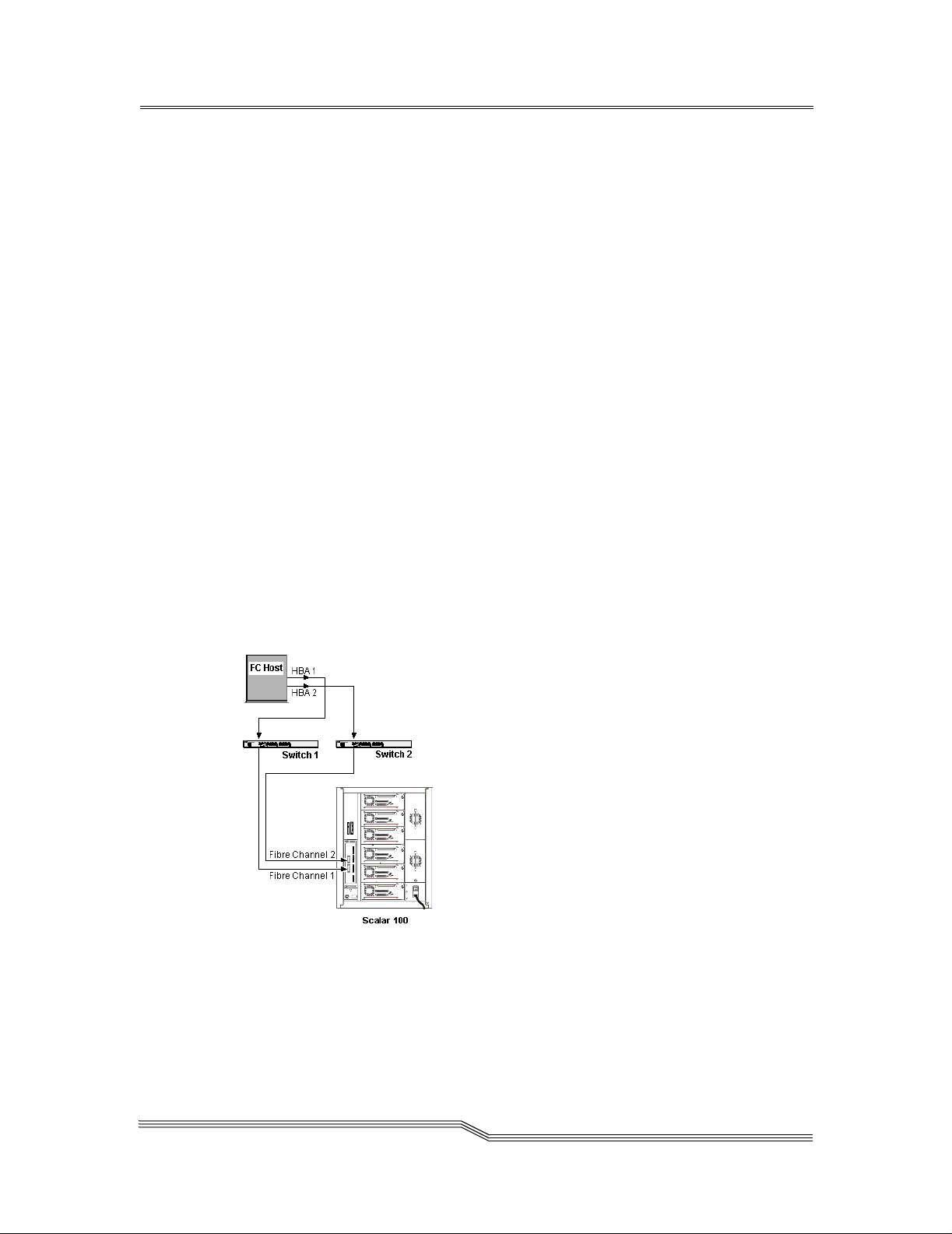
The SNC is the interface between storage and Open System Host interfaces and provides
Fibre Channel to SC SI connectivity as we ll as the ability to mana ge the library and other
devices within the storage network. One possible configuration is illustrated in Figure 1-1.
Introduction
Figure 1-1: Configuration Overview
page 9
Page 24
Configuration Support
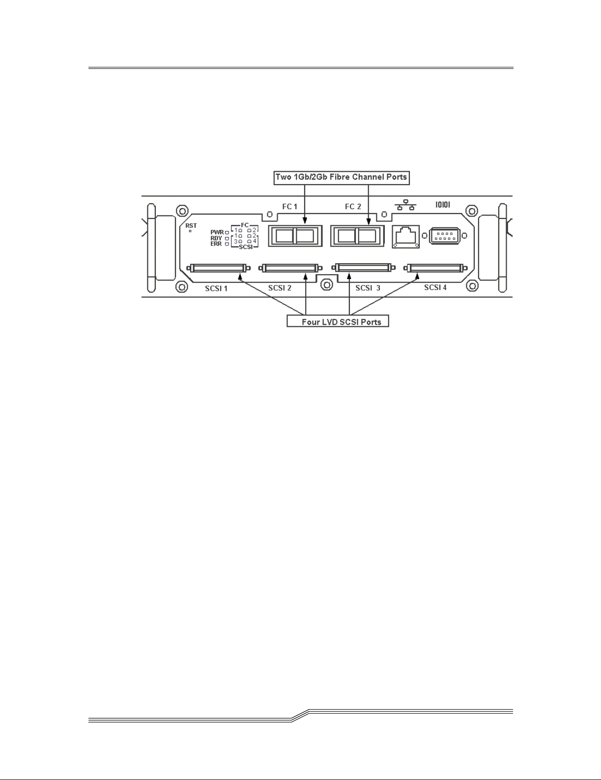
The SNC provides two Fibre Channel interfaces. The FC interfaces are configured with
Giga Bit Interface Converter (GBIC) modules. In addition, the SNC has four Ultra2 SCSI
interfaces. The Ultra2 interfaces are Low Voltage Differential (LVD). See Figure 1-2:
Figure 1-2: Configuration Detail
Address Mapping
The SNC maps addresses across and between these different interfaces and preserves the
persistency of the address maps across power ups of systems, devices, and the SNC. The
SNC supports the attachment of up to 2048 unique devices across multiple interfaces.
Interface Protocol Awareness
The SNC processes SCSI-3 and SCSI-2 protoc ols for disk, tape , and tape medium changer
devices. It can report the host and devices that are attached to its interfaces. The SNC has
the capability to manage the access security between end points on the Fibre Channel
interfaces and the SCSI channels.
ADIC Management Console
The ADIC Management Console offers full capability for remote management,
configuration, and event notification. Each SNC has internal Event Logging, Event
Analysis, and periodic Health Checks for predictive failure analysis. All of these
management, configuration, and notification capabilities are accessible via standard
SNMP protocol for use with major network management applications. The ADIC
Management Console is a value-added software application for remote management and
configuration.
page 10
Configuration Support
Page 25

Access Security Capabilities
The SNC is aware of the hosts and devices that are attached to its interfaces and provides
access security between hosts and devices. Access security between different hosts and
devices is a requirement for m ulti-initiator SAN solutions. Using the ADIC Management
Console you can partition the SAN for different levels of access and performance.
The SNC provides two tools for managing access security: Channel Zoning and Scalar
Firewall Manager. Depending upon the unit you have purchased one or both of these
options will be available.
Scalar Firewall Manager Option
Scalar Firewall Manager (SFM) technology e nabl es Storage Area Networks with multiple
users to share the same connectivity channels or pipes to access the same or different
storage elements or resources. Therefore, multiple virtual private connections can be
created on the same Storage Networking infrastructure.
SFM is a Virtual Private connection or channel between a storage element and the user of
that element in a Storage Area Network. Scalar Firewall Manager is a method of Access
Security that manages the access between an Initiator (user, host, system, ..) to Target/
LUN (Device, Disk or Tape, ...) and also protects and preserves such permission.
• SFM is completely host independent and requires no software components on the
host.
• SFM has no interface dependencies and supports Fibre Channel, SCSI or any other
SAN interface.
• SFM supports SAN connectivity/fan-out products such as hubs and switches.
• SFM is independent of the storage elements and requires no change in legacy or
new storage devices.
An optional automatic host registration service that sends periodic host status information
to SFM is provided.
SFM is an optional software capability for the SNC tha t re quires a license key to be
enabled.
Channel Zoning
Channel Zoning is a mean s of managing the access se curity between SAN connections a nd
SCSI channels on a channel by channel basis.
• Channel Zoning can be used to secure access between a server and its storage,
segregating them, for example, from other servers and their respective storage.
• The default settings allow all SAN connections to access all SCSI Channels.
Configuration Support
page 11
Page 26

The Channel Zoning capability is always available to users of the SNC.
Data Mover Module
The SNC can move data directly between storage devices that are attached to it. This
direct movement of data can be f rom disk to disk, disk to ta pe , t ape to di sk or t ape t o t ape .
The Data Mover Module frees-up valuable system resources on the server and
substantially increases the speed of backup and restore operations.
• The Data Mover Module is the engi ne for Ser ver-F ree backup and r estore and HSM
applications that support the Extended Copy Specification (ANSI T10/99-143r1).
The Data Mover Module capability is always available to users of the SNC.
Hardware Pr oduct Description and Features
This section describes the capabilit ies of the pro duct and out lines some o f the key features
of its interfaces.
• An IBM 405GP 200 MHz processor, with integrated instruction and data caches,
and internal serial I/O and Ethernet interfaces
• An Intel 80303 100 MHz Processor, with integrated instructi on and data caches
• 32 MB ECC protected SDRAM program memory
• 128 MB ECC protected SDRAM data buffer memory
• FLASH memory for operational firmware, power on self-test code, diagnostic
functions, and system u tilities.
• Non-volatile SRAM for persistent configuration tables and event logs
• VxWorks real-time operating system (RTOS)
Fibre Channel Interfaces
Interfaces for host and device attachment include two 2-Gb/s bi-directional Short Wave
connections.
Table 1-1: Fibre Channel Connections
Connection Type Connector Cable Type Speed Distance
Optical Short Wave Duplex SC 62.5 µ multimode 1.062.5 Mb/sec 300 m
Optical Short Wave Duplex SC 50 µ multimode 1.062.5 Mb/sec 500 m
The Giga-Bit Interface Converter can interoperate with both 2 Gb/ s an d 1 Gb/ s data l in ks.
The GBIC is hot-swappable and is the only component, except for the SNC module itself
page 12
Hardware Product Description and Features
Page 27

that is a Field Replaceable Unit (FRU). See “Removing and Replacing the GBIC” on
page 154.
Cables should have a duplex SC connector on the GBIC end and a connector appropriate
to the HBA in use on the ho st end.
Fibre Channel interfaces support the following Public and Private Loop modes:
•Target
• Initiator
• Target and Initiator
Fibre Channel Interfaces also support the following connection options:
• Loop
• Point-to-Point
• Loop Preferred
The Fibre Channel interface controller is in compliance with the following standards and
specifications:
• Fibre Channel Arbitrated Loop (FC-AL-2) working draft, rev 6.4, August 28 , 1998
• Fibre Channel Fabric Loop Attachment (FC-FLA) working draft, rev 2.7, August
12, 1997
• Fibre Channel Private Loop SCSI Direct Attach (FC-PLDA) working draft, rev 2.1,
September 22, 1997
• Fibre Channel Tape (FC-TAPE) profile, T11/98-124vD, rev 1.13, February 3, 1999
• Fibre Channel protocol SCSI (FCP-SCSI)
• Fibre Channel internet protocol (IP)
• Fibre Channel virtual interface (FC-VI)
Ultra2 SCSI I/O Interfaces
• Four Low Volta ge Differential (LVD) Ultra2 SCSI channels with internal
termination.
• SCSI channels have automatic speed and width negotiation capability for wide or
narrow bus widths and Standard, Fast, Ultra or Ultra2 speeds. These parameters can
be viewed from the ADIC Management Co nsole.
• SCSI channel support for up to 15 SCSI target IDs and up to 32 LUNs per ID
(subject to an overall total of 2048 devices). The SNC uses one LUN for command
and control so that the remaining 2047 LUNs are available for SCSI devices. For
each Fibre Channel interface, the SNC occupies one Fibre Channel ID and all SCSI
target devices are available as LUNs on the same Fibre Channel ID.
Hardware Product Description and Feat ure s
page 13
Page 28

• The unit provides four SCSI-3 VHDCI connectors for maximum mechanical
reliability.
The SCSI interfaces are compliant with the following SCSI specifications:
• ANSI T10/1071D Rev. 6, SCSI-3 Fast-20
• ANSI T10/375D Rev. 10t, SCSI-2
• ANSI T10/1142D Rev 20b, SCSI-3 Parallel Interface-2
Ethernet
The 10/100 Base-T Ethernet port has an RJ-45 connector for out-of-band management. It
can be connected to a network hub, switch, or router using an unshielded twisted-pair
Ethernet cable. The Ethernet port complies with the IEEE 802.3 specification.
Service Port
The service port is an RS-232 connection with a 9-pin D-shell connector (DTE). It
connects to the host serial port with a 9-pin to 9-p in null-modem cable. It is c ompatible
with serial ports on personal computers.
The service port is used for local service and diagnostics when you use a terminal session
to access the shell interface.
The service port is configured at:
• 19,200 Baud
• 8 data bits
•No parity
•One stop-bit
• Hardware Flow Control or Xon/Xoff
LED Indicators
The User panel of the SNC provides LEDs t hat i ndicat e the statu s and act ivi ty of t he SNC
and its interfaces.
Figure 1-3: LEDs
page 14
Hardware Product Description and Features
Page 29

When the SNC is first turned on, some of the LEDs will be on and others will flash while
it is booting.
The following list brie fly describes how to interpre t the LED signals. See also “POST
Error Codes” on page 255.
FC 1-2
• For each FC Channel, the LED will be OFF when the Channel is not connected. It
will be ON when the Channel is connected to a live Fibre Channel device. It will
flash when there is activity on the Channel.
SCSI 1-4
• For each SCSI channel, the LED will be OFF when no devices have been detected
on the port. It will be ON when a target has been found on the channel. It will flash
when there is activity on the channel. The LED will re turn to the OFF state if th e
channel is reset.
PWR
•The PWR (Power) LED will be ON when the SNC has power. It will flash if the
on-board power sensors determine that any of the required supply voltages are out
of range.
RDY
•The RDY (Ready) LED indicates status of Ready. Normally the RDY LED flashes
when the SNC has finished booting. If the RDY LED remains ON or OFF for more
than a few seconds, it means there is a problem.
•The RDY LED will flash rapidly, 4 times per second, when the SNC is runnin g in
diagnostic mode.
ERR
•The ERR (Error) LED indicates that an error condition exists. This may indicate
such errors as over-temperature conditions, fan stalled or other internally detected
error conditions. See “POST Error Codes” on page 255.
Supported Platforms
The SNC is a platform-independent product. You can connect a host to the SNC after you
have installed the appropriate host bus adapter and drivers. You can also connect host
systems with different operating systems to the SNC through either SCSI or Fibre
Channel.
For a current list of supported platforms, configurations, and host bus adapters, visit
“Service and Support” at www.adic.com
.
Supported Platforms
page 15
Page 30

Supported Devices
The SNC supports connections to the Scalar 100 tape library and supports all tape drives
available for that unit.
For a current list of supported devices, visit “Service and Support” at www.adic.com.
Operating Specifications
This section contains the physical, electrical, and environmental specifications for the
product.
The SNC is enclosed in the Scalar 100 tape library. Only the Front Panel of the unit is
visible from the back of the Scalar 100.
The external dimensions are:
• 2.56” high
•12” deep
• 10” wide
• weight:3.62 lbs.
In order to provide a safety margin and permit adequate cooling, the unit is fitted with a 12
VDC tach-output blower. Should temperatures exceed specifications, an environmental
alarm violation is sent and logged in a non-volatile location immune from customer
erasure, permitting environmental causes of failure to be determined.
Operating Environment
• Operating Temperature: 5° C to 45° C (41° F to 113° F)
• Storage Temperature: -40
• Humidity: 10%-85% Operating, Non-Condensing
5%-95% Non-operating, Non-Condensing
° C to 70° C (40° F to 158° F)
Power Consumption
The SNC is powered by the Scalar 100 tape library. Maximum power consumption is 55
watts, in active mode. SCSI channel termination power is drawn from the Scalar 100 tape
library drive sleds, not the SNC.
The power supply status is monitored as part of the Enclosure Monitor Register and is
reported by the front panel LED, and to the ADIC Management Console.
page 16
Supported Devices
Page 31

Introduction to the ADIC Management Console
The ADIC Management Console uses a combination of industry-stand ard Simple Network
Management Protocol (SNMP) requests and a method or techn olo gy known as SCSI over
TCP, which encapsulates SCSI commands and/or data in TCP packets.
Client/Server Model
Figure 1-4: Client Server Model
The ADIC Management Console is part of a three-part client/server model.
Agent
Each SNC is a stand-alone, SNMP-manageable host. The ADIC Management Console
uses SNMP as the primary method of communication with the agents. This allows you to
set and retrieve information that controls the operation of the agent. It also provides alerts
(traps) when an event has occurred that requires intervention. The SCSI/TCP component
allows you to update firmware on the SNCs and target devices and manipulate device
operating parameters. The agent component is embedded in the operating software of the
SNC.
Server
The Server component is a Java application that runs on a host computer system (see
“Installation Requirements” on page 39). The server is respo nsible for maintaining
communication with the managed agents, and acts as an intermediary between the agent
running on the SNC and multiple Clients. It provides security features by mainta ining
account names and passwords on behalf of the Client application. By keeping track of
different Client views, a user can recall a saved view from any Client.
The Server coordinates the requests from multiple clients to manage multiple SNCs.
Communication between the Server a nd t he agent s i s carri ed o ut ei th er by SNMP or SCSI/
Introduction to the ADIC Management Console
page 17
Page 32

TCP, as required. Specifically, the Java Management Application Programming Interface
(JMAPI) is used where possible to provide an industry standard and transportable
interface. All communication between th e Clients and the Server is i mplemented usin g the
Java Remote Method Invocation (RMI), a form of remote procedure call (RPC).
The Server is written to be both transportable and efficient . Multiple Clients can share data
the Server already knows about rather than having to request the data again. In addition,
the Server receives all traps from the agents and forwards them to the Clients that have
registered to receive them.
Client
The Client is a Java application. One or more Clients connect to a Server in order to
manage SNCs. The Client operates from any compatible computer, as long as a TCP/IP
connection is established to the Server component. This allows for dial-in configurations
using Point-to-Point Protocol (PPP), intranet, or Internet access (where allowed by local
network policy and firewall configurations). If the client is started on the same host as the
server, the connection will automatically be established.
The Client is the application that provides the user interface and allows viewing and
manipulating of all SNCs and device parameters. Each Client can be configured by the
individual user to show on ly the SNCs of interest. Con s e qu ently, one Client can monitor
one set of SNCs and other managers can be responsible for totally different SNCs, without
interfering with each other.
For some operations the Client uses Java RMI calls to communicate with the server, and
SCSI over TC P to communicate with the SNC.
Features
SNMP
SNMP community strings are a part of the software agent’s messaging functionality that
serve to group network devices into logical collections for management purposes. The
community strings on the Server must match those on the SNC you wish to manage.
There are three different strings defined for the SNC:
Read for querying the SNC
Write for controlling the SNC
Trap for receiving event messages from the SNC
The SNC can maintain 32 Read and 32 Write community strings and 1 Trap
community s tring.
page 18
Features
Page 33

SNMP Community Support
A set of commands is provided for manipulating the SNMP Community strings. These
strings act as passwords for authenticating requests made from managing applications
such as the ADIC Management Console.
There are three different communities defined: Read (allows “Gets” only), Write
(allows “Sets”, i.e., changes to be made) and Trap (defines the Community string that a
trap recipient will allow). In order for a managing application to view or control an SNMP
agent (such as the SNC), it must provide the correct community string for each request.
The SNC allows up to 32 community strings for each of the Read and Write
communities. There is only a single Trap community string.
Security
Logging on to a serv er is r equired to manage t he SNC via the ADI C Mana gement Conso le
application. Two levels of privilege control what type of access is allowed:
Administrator
Allows full access, including changing parameters
User
Allows viewing of data and parameters only
Service Port access is managed with User ac counts cre ated via tel net or the seria l interface
on the SNC.
SAN Access Control
Access control features include Channel Zoning and optional Scalar Firewall Manager
(SFM).
Channel Zoning allows selected SCSI channels to be available to selected SAN
connections.
The SFM option requires a software license key t o enabl e t he Init iator-Target/LUN access
control feature. SFM manages access permission between any host attached to an SNC
SAN connection and any storage element attached to the SNC. This includes storage
devices attached to any SCSI Channel and storage devices attached to any other SAN
Connection on the SNC.
Features
page 19
Page 34

Host Registration Service
The Host Registration Service is software that installs on the host from the CD-ROM or it
can be downloaded from www.adic.com. It simplifies SFM configuration for the system
administrator . It removes the burden of ph ysical ly tr acing each connection to correlate t he
HBA World Wide Name (WWN) with a specific host.
The registration service installs on most host platforms and it provides the SNC with
periodic host status information including the host name, host type and type of HBA
installed. Host information is sent over the host Channel connection to the SNC.
Once installed, the service runs automatically and does not require further system
administrator interaction. From the ADIC Manag ement Console, you can see the Channel
that the host is connected to and you can tell whether the host is on or offline.
Saved Views
Each user can store their own preferred views on the server. Loading a previous view
automatically connects the user to one or more SNCs in a single step rather than
specifying connections to SNCs individually. Because they are stored on the server, the
same views are available to the user from any client.
Network Discovery
Network discovery allows you to locate any SNC based on network addresses and
network masks. This allows management of an SNC without knowi ng the specific Internet
Protocol (IP) address beforehand. Alternatively, the IP address (or name, if it can be
resolved through DNS) of an SNC can be entered directly for instant access.
Configuration Options
You can set up an SNC with a number of non-default parameters, channel settings, and
event management variables. For more informatio n, see the “Controls Menu Gro up” on
page 72.
Software Updates
You can update the SNC firmware from the client. For more information, see “Update
Firmware” on page 90. You can also send device micro-code to individual target devices
as a means to update their firmware using the same method that you use to update SNC
firmware.
page 20
Features
Page 35

Event Logging
You can retrieve and view the SNC event logs in a table. Filtering based upon the
significance of events simplifies fault isolation. For more information, see “Events” on
page 65.
Health Checks
Instantaneous and periodic health checks allow monitoring of each SNC and the devices
attached to it. The level and interval of the health check is selectable to obtain greater
confidence or minimize the impact on system performance. For more information, see
“Health Check” on page 63.
Views
Two different viewing modes are available.
Tree View shows all available SNCs and can be expanded to show greater levels of detail.
For more information, see “View Menu Group” on page 55.
Figure 1-5 shows the Front Panel vie w, which shows the status of the LED indicators for a
selected SNC.
Features
Figure 1-5: LED Indicators on Front Panel View
page 21
Page 36

Heartbeat
Each component of the ADIC Management Consol e monitors t he componen ts with which
it communicates to ensure continuity of service. If the SNC is no longer available, the
server component notifies monitoring clients. For more information, see “Health Check”
on page 63.
page 22
Features
Page 37

Chapter 2: Installation
This section covers installa tion of the SNC, SCSI devices, host adapter, and ADIC
Management Console software. ADIC professional services are required for SNC
installation.
Instructions on how to in stall the product is divided into three sections:
Pre-installation Checklist:
Before the service representative installs the S NC, check the i tems on the Preinstallation Checklist.
Installation Checklist:
The installation checklist has instructions on how to install the SNC.
Post-installation Checklist:
After the service representa tive installs the SNC, follow th e post-installation
checklist to complete the installation.
Pre-installation Checklist
It is important that the i tems in this checklist are verified before install ation of the SNC
begins. This ensures a successful installation of the product.
Table 2-1: Pre-Installation Steps
Step Customer Action or Decision Comments and References
Verify host platform OS required
1
Service Pack installed,
For example: Windows NT 4.0,
Service Pack 6a (or later).
Verify required Fibre Channel Host
2
Bus Adapter, HBA BIOS and
device driver have been procured
and are installed in host system(s).
See “Host Bus Adapter Setup” on
page 36.
For a current list of supported platforms
required host platform code updates and
information on how to obtain them, visit
“Service and Support” at www.adic.com.
For a list of supported HBAs and the
required BIOS and device driver, visit
“Service and Support” at www.adic.com.
Installation
page 23
Page 38

Table 2-1: Pre-Installation Steps
Step Customer Action or Decision Comments and References
If you will be connecting more than
3
one host to the
to use the Scalar Firewall Manager
access option, be sure you have the
necessary license.
If you are using Scalar Firewall
4
Manager, install the Host
Registration Service on t he hosts
that will be connected to the
Ensure that all host Fibre Channel
5
cables
° Have been ordered with the
product or
° Have been preinstalled and
checked
° Are labelled with:
---Host system identifier
SNC and you want
---Scalar 100 tape library system
identifier.
Label both ends of each SCSI cable
6
with:
° Drive ID and
number.
SNC connector
See “Access Options” on page 74.
For Windows NT/Windows 2000, see
“Installing the SAN Explorer and Host
Registration Service” on page 37.
SNC.
For Solaris, AIX and other platforms, see
“Installing the Host Registration Service”
on page 37.
Refer to the HBA Specification provided
with your HBA.
None.
page 24
Pre-instal lation Checkl is t
Page 39

Table 2-1: Pre-Installation Steps
Step Customer Action or Decision Comments and References
Decide on network parameters.
7
Ethernet port configuration
decisions:
Static IP address____________
Netmask (if required)_________
User-defined
(optional)__________________
If the
SNC is not on the same TCP/
IP subnet as the server*, assign the
default network gateway address
and/or route table entries:
________________________
*’Server’ in this context, means the
computer used for the ADIC
Management Console server
application.
Attention: Save this configuration
information for future reference.
Run the Ethernet cable from the
8
server (the computer that is
designated to run the
Management Console
software) to the network hub.
SNC name
ADIC
Server
Obtain the network parameters from your
network administrator.
Attention: Use of incorrect network
parameters can cause problems on the
Ethernet network.
The default network name is the unit’s
serial number. If you choose a different
name, it becomes the prompt displayed on
the service terminal. Choosing a different
name may be useful if you have more than
one
SNC. To change the name, use the
"hostNameSet" command on page
203.
None.
Pre-installa tion Checklist
page 25
Page 40

Figure 2-1: Placement of Thumbscrews on Unit
Installation Checklist
The installation checklist has instructions on how to install the SNC with SCSI attached
storage and Fibre Channel attached hosts. ADIC professional services are required for
SNC installation.
.
Table 2-2: Installation Steps
Step Actions Comments and References
Acquire information for Ethernet
1
installation.
Insert the SNC in the empty bay of the
2
Scalar 100 tape library. Align the
power connection and seat unit firmly.
Tighten the two thumbscrews. See
Figure 2-1.
Refer to Step 7 in Table 2-1: PreInstallation Steps.
None.
page 26
Installatio n Checklist
Page 41

Table 2-2: Installation Steps
Step Actions Comments and References
Connect the service terminal to the
3
Service Port and start a terminal
emulation session.
Run the Ethernet cable from the
4
network hub to the
To connect the SCSI cables
5
appropriately, see “Library and
Controller Cabling to Drives” on
page 28
SNC.
6 Turn on the Scalar 100 tape library.
7 After the Scalar 100 tape library has
finished cycling on, issue the
targets command from the service
terminal. It can take up to about 30
seconds for the devices to be available
for discovery.
See “Connecting to the Service Port” on
page 163 for the required parameters.
None.
None.
Within one minute, the RDY LED on
the
SNC should start flashing once per
second and the “done executing startup
script” message should be displayed on
the service terminal.
Some time after
that, the Scalar 100 tape library will
also become available.
See the "targets" command on
page 241.
If all attached SCSI targets are not
and the Scalar 100 tape library
shown
is finished with its power-up, go to
“SCSI MAP” on page 134.
Installation Checklist
Configure the Ethernet Port (Host
8
Name, Address, Routes, reboot)
Observe Ethernet Link LED.
9 Issue hostTypeShow command
from the service terminal to view host
type settings for the Fibre Channel
ports.
If the hosts that will be connected are
not the type shown, issue
command from the service terminal to
set the host type for each Fibre
Channel port.
setHost
Configure the Ethernet Port using
information in Step
Installation Steps.
Refer to
“SNC Network Setup” on
7 in Table 2-1: Pre-
page 157.
If the Ethernet Link LED is not on, go
to the “Ethernet MAP” on page 147
See the "hostTypeShow"
command on page 204.
See the
[port],“OS”"
224.
"setHost
command on page
page 27
Page 42

Table 2-2: Installation Steps
Step Actions Comments and References
Power down the FC host(s).
10
Connect the FC cables from the FC
HBA(s) to the
Power up the FC host(s).
SNC.
11 Issue fcShow command from the
service terminal to show the status of
the FC interface that is installed and
connected.
fcShowDevs command from
Issue
the service terminal to show SCSI
target devices that are connected as
seen by the Fibre Channel interface.
Verify all target devices are available
12
to the host system.
Perform steps in Table 2-6: “Post-
13
Installation St eps” on page 35.
If the FC1 and/or FC2 Connection
Status LED for the attached host(s) is
not on, check FC cables. You may have
to change the polarity of the FC cables.
If problem persists, go to the “Fibre
Channel MAP” on page 142.
See the "fcShow [level] "
command on page 194.
Look for FW State=Ready for each FC
interface. If FW State NOT=Ready, go
to the “Fibre Channel MAP” on
page 142.
See the
page 195. If all devices are not shown,
go to the “SCSI MAP” on page134.
Use appropriate host system utilities for
disk and tape. If all devices are NOT
available, reboot host system(s) and
check again. If problem persists, go to
the “SCSI MAP” on page 134.
In SAN Configurations, two specific
areas require understanding and
attention:
Access Security
Save Configuration
"fcShowDevs" command on
page 28
Library and Controller Cabling to Drives
The following illustrations represent maximum load balancing and throughput for a
system involving two hosts, eac h of which is co nnec ting to a Fibre C hannel por t thr ough a
switch. A variety of other configurations are possible, each involving a particular number
of host systems, the presence or absence of switches, and user needs.
Figure 2-2 shows the SCSI Cab ling for one Drive and one Cha nnel .C hann el Zoning is not
typically used when a single Channel is cabled.
Installatio n Checklist
Page 43

Figure 2-2: SCSI Cabling for One Drive and One Channel
Refer to Figure 2-3 for the most effective Channel Zoning for balancing load across two
SCSI Channels. Figure 2-4 shows SCSI Cablin g for two Drives over two Channel s. Figure
2-5 shows SCSI Cabling for three Drives over two Channels. Table 2-3 summarizes the
appropriate SCSI Cabling for one, two, or three Drives over two Channels. These are the
most effective configurations in terms of throughput.
Figure 2-3: Channel Zoning for Two SCSI Channels
Installation Checklist
page 29
Page 44

Table 2-3: Cabling for Two or Three Drives Over Two Channels
SCSI 1 SCSI 2 SCSI 3 SCSI 4
Library
Drive 1
Drive 2
Drive 3
X
X
X
X
page 30
Figure 2-4: SCSI Cabling for Two Drives and Two Channels
Installatio n Checklist
Page 45

Figure 2-5: SCSI Cabling for Three Drives and Two Channels
Refer to Figure 2-6 for the most effective Channel Zoning for balancing load across four
SCSI Channels. Table 2-4 summarizes the appropriate SCSI Cabling for four Drives over
four Channels. Figure 2-7 shows four Drives over four Channels as seen from the back of
the Scalar 100 tape library. Table 2-5 summarizes the appropriate SCSI Cabling for five or
six Drives over four Channels. Figure 2-8 shows cabling for five Drives and four
Channels. Figure 2-9 shows cabling for six Drives and four Channels. These are the most
effective cabling configurations in terms of throughput.
Figure 2-6: Channel Zoning for Four SCSI Channels
Installation Checklist
page 31
Page 46
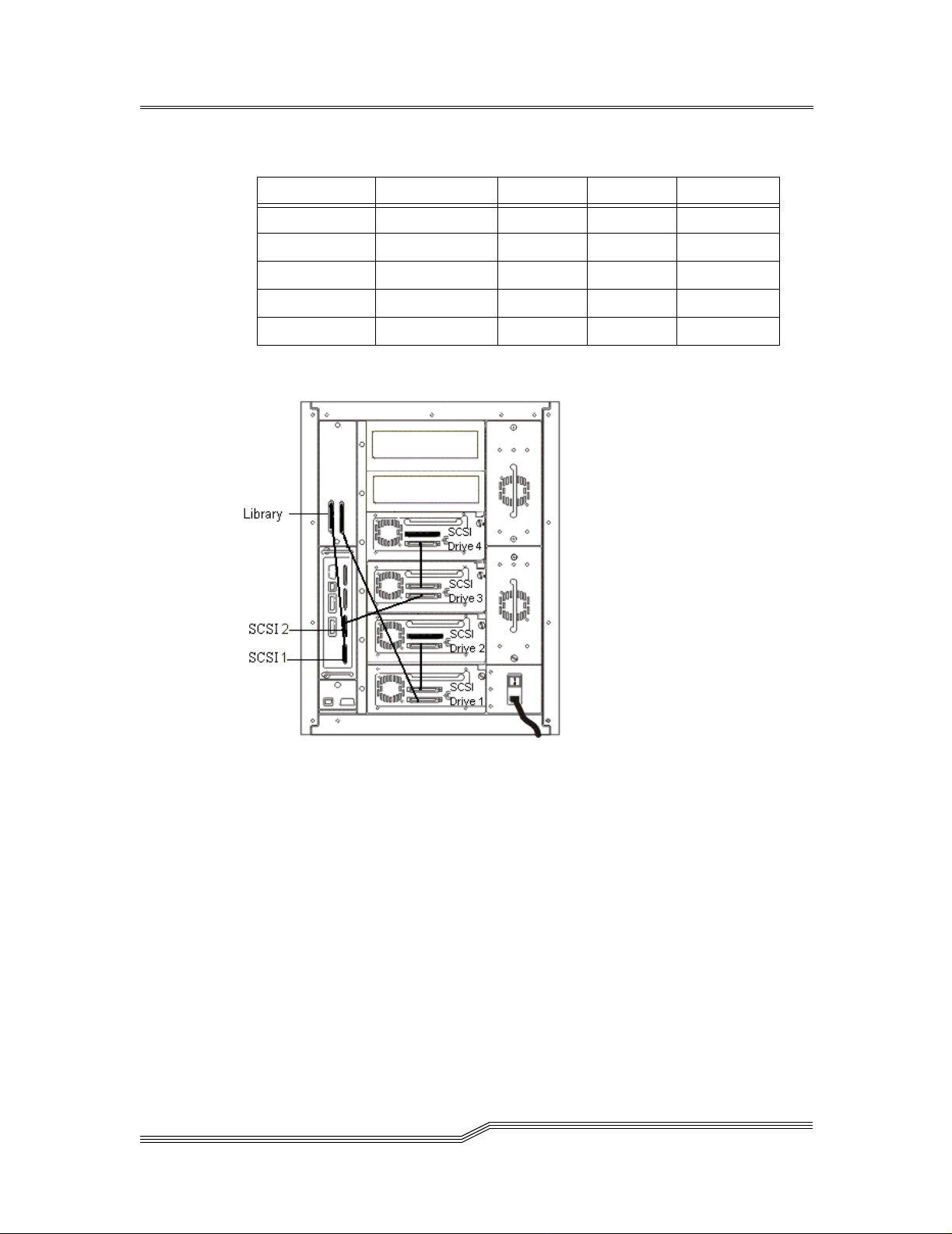
Table 2-4: Cabling for Four Drives over Two Channels
SCSI 1 SCSI 2 SCSI 3 SCSI 4
Library
Drive 1
Drive 2
Drive 3
Drive 4
X
X
X
X
X
page 32
Figure 2-7: SCSI Cabling for Four Drives and Two Channels
Installatio n Checklist
Page 47

Table 2-5: Cabling for Five or Six drives Over Four Channels
SCSI 1 SCSI 2 SCSI 3 SCSI 4
Library
Drive 1
Drive 2
Drive 3
Drive 4
Drive 5
Drive 6
X
X
X
X
X
X
X
Figure 2-8: SCSI Cabling for Five Drives and Three Channels
Installation Checklist
page 33
Page 48

Figure 2-9: SCSI Cabling for Six Drives and Four Channels
page 34
Installatio n Checklist
Page 49

Post-installation Checklist
Perform the actions listed in Table 2 -6 after the service repres e ntative has completed the
installation steps.
Table 2-6: Post-Installation Steps
Step Customer Actions Comments and References
1 Install the ADIC Management Console
software.
For an updated list of support ed systems,
visit “Service and Support” at
www.adic.com.
Ensure that the designated system has
2
access to the same Ethernet subnet as the
SNC.
3 Start-up the ADIC Management
Console
Server.
4 ° Start-up the ADIC Manage ment
Console
° Connect to the server (if it does not
find the server running on the same
system).
° Log on.
° Add new administrator account and
password. This removes the default
account.
° Log off and log on using the new
administrator account.
client.
See “Install the ADIC Management
Console Software” on page 38.
The designated system will be used
as the central point for monitoring
and controlling
Be sure to have completed Step 8 in
T a ble 2-1 and Step 4 in Ta ble 2-2.
Consult your network administrator.
See “Startup and Configuration” on
page 40.
Connect using the name or IP
address of the designated server
system.
See “Startup and Configuration” on
page 40.
SNCs.
Post-installation Chec klist
From the client, connect to the desired
5
See “Connect” on page 61.
SNC(s).
Save your user/administrator view. See “Save Current View as” on
6
page 53.
page 35
Page 50

Table 2-6: Post-Installation Steps
Step Customer Actions Comments and References
If later firmware is available, perform
7
the following for each
° Update firmware
° Restart
If you chose an Access Control option in
8
Table 1, Pre-installation Checklist step
4, use the Channel Zoning or ADIC
Management Console to enable Access
Control.
SNC:
9 At this time, you MUST save the SNC’s
configuration.
10
Become familiar with using the ADIC
Management Console.
11
You must use the ADIC Management
Console to monitor and maintain your
Storage Area Network.
If a trap/event is reported by the
ADIC
Management Console, check the
reported event code, then see “Remote
Event Notification” on page 259 and
perform the recommended action.
See “Control s Menu Grou p” on
page 72.
T o obt ain in for mat ion abou t
firmware updates, visit “Service and
Support” at www.adic.co m
See “Access Options: Channel
Zoning” on page 74.
See “Scalar Firewall Manager” on
page 99.
See “Save SNC 5101
Configuration” on page 70.
See “Using the ADIC Manageme nt
Console” on page 43.
None.
page 36
Note: We highly recommend that you save your SNC configuration periodically. You
MUST save your configuration if you add or remove devices, or if you make changes
to access control or other operating parameter settings.
Other Installation Issues
Host Bus Adapter Setup
Hosts are connected to the SNC through specific Host Bus Adapters (HBAs). The
installation procedure varies slightly, depending on which adapter you will be using. The
procedure involves these steps:
1. Install the adapter in the host system, following the manufacturer’s recommendations.
2. Power on the host system and update the adapter firmware, if necessary.
Other Installation Issues
Page 51

3. Boot the operating system and install the device driver for the HBA.
4. Reboot and verify that the device driver has started and that expected target devices
are seen by the operating system.
5. Install optional utility so ftwa re, if desired.
Perform steps 4 and 5 after the SNC is installed and connected to the host system.
Installing the SAN Explorer and Host Registration Service
The SAN Explorer software is only available for hosts running the Windows NT or
Windows 2000 operating systems. It allows viewing all connected Fibre Channel and
SCSI devices. In addition, you can update the code on all devices and view the LUN
mapping through switches to which your SNC may be attached. The software also has an
option that lets you choose to install the Host Registration Service for the Scalar Firewall
Manager.
See the readme file on the CD-ROM for installation instructions. For software updates,
visit “Service and Support” at www.adic.com
Installing the Host Registration Service
The Host Registration Service for
Scalar Firewall Manager provides the SNC with periodic
host status inform ation inclu ding th e host name, ho st typ e and H BA. I t is a vaila ble wit hout
the SAN Explorer software for host operating systems other than Windows NT or
Windows 2000. Host information is sent over the host connection to the SNC. Once
installed, the service runs automatically and does not require further system administrator
interaction. From the ADIC Management Console, you can see the Fi bre Channel or SCSI
port that the host is connected to and you can tell whether the host is on or offline.
The default period is set to send host st atus ever y 15 minutes. I f you want, you can change
the period to any v alue between 1 and 255 minutes. See the readm e file on the CD-ROM
in the HOSTSW folder for the specific host platform you are using. The readme file
contains the installation procedure and information about changing how often host status
information is sent.
For Windows NT and Windows 2000: See the readme file in the NT/HOSTSW folder
on the CD-ROM. The Host Registration Service installs as part of the SAN Explorer
executable. For software updates, visit “Service and Support” at www.adic.com.
For Solaris: A single program is provided for Solaris that runs from the command line or
by inclusion in a startup script. Installation is through a Solaris "package". See the readme
file in the SOLARIS/HOSTSW folder on the CD-ROM. For software updates, visit
“Service and Support” at www.adic.com.
Other Installation Issues
page 37
Page 52

For AIX: See the readme file in the AIX/HOSTS W folder on the CD-ROM. For
availability and information regarding software updates, visit “Service and Support” at
www.adic.com.
For other platforms, such as HP-UX: See the appropriate readme file on the CD-ROM.
For availability and information regarding software updates, visit “Service and Support”
at www.adic.com.
Power-Up and Boot Sequence Guidelines
The SNC scans the SCSI buses after it boots. If you add or remove SCSI devices after the
SNC has booted, it will not detect the changes. You can invoke a SCSI rescan or reboot
from the ADIC Management Console client or from the service terminal.
Before you turn on or restart the hosts that are connected to the Scalar 100 tape library,
you must wait until the SNC has finished booting. You will know that the SNC has
finished booting when the RDY LED on the user panel blinks at intervals of one second.
Some operating systems provide you with software methods that allow you to add or
remove SCSI devices dynamically after the host has booted. To ensure reliable operation,
reboot the host.
If you update SNC firmware you must reboot in order to use the new firmware. To ensure
compatibility between the firmware features or functions and the host, reboot the host.
If you update SCSI device firmware, the SAN Explorer application does not display the
new firmware version until the SNC has issued a SCSI Inquiry. The SCSI Inquiry occurs
when it rescans the SCSI buses. The same is true for the ADIC Management Console
client application and the service terminal.
Install the ADIC Management Console Software
The ADIC Management Console allows you to manage multiple SNCs from any location
on your network. The system consists of two Java applications. You should install the
Server on a single system on yo ur network t o manage multi ple SNCs f rom multip le ADIC
Management Console Clients.
This section describes the installation and initial configuration of the Server and Client
components. The installation for the ADIC Management Console consists of three
components, as described in “Client/Server Model” on page 17. The agent component is
provided as part of the operating software already installed on the SNC hardware.
The installation program installs the ap propri ate soft ware co mponen ts on y our Server and
Client system. It also installs the required Java Runtime Environment.
page 38
Other Installation Issues
Page 53

SERVER
The system used for the Server do es not need to be used as a Client and can be placed in a
locked closet. It does need networ k access to the SNCs it will be managing, so ap propri ate
routes will have to be set on that system and on the SNCs.
CLIENT
The Client system can be located anywhere, as long as it can connect to the Server system
using TCP/IP.
Installation Requirements
Minimum configuration guidelines are presented for each system platform in the readme
file located in the SANMGMT folder on the CD-ROM. For an updated list of supported
platforms and installation instructions, visit “Service and Support” at www.adic.com.
An example of the installation requirements for Windows NT/Windows 2000 is listed
below.
Installing the Software on Windows NT/Windows 2000
Server System Requirements
• Windows NT 4.0 Server or Workstation, Service Pack 6a or Windows 2000
• Minimum memory: 96MB
• Free hard disk space: 40MB
• Ethernet with TCP/IP protocol installed
Client System Requirements
• Windows NT 4.0 Server or Workstation, Service Pack 6a or Windows 2000
• Minimum memory: 96MB
• Free hard disk space: 30MB
• Ethernet with TCP/IP protocol installed
1. Log on to the target machine with administrator privileges.
2. Insert the CD and run MC272WIN.exe from the x:\NT\SANMGMT directory, where
x is the letter of your CD-ROM drive.
Other Installation Issues
page 39
Page 54

3. The default install option is set to install both the ADIC Management Console Server
and Client. When you install the ADIC Management Console on any other attached
system, you can opt to install the Client only.
Startup and Configuration
The first time you install the server component, there is one pre-defined user account,
which has administrator privileges. That account is called admin and the password is
password.
Note: User names and passwords are case sensitive.
START THE SERVER APPLICATION
1. Click on the Windows NT/Windows 2000 Start button
2. Select Programs > ADIC > Server
START THE CLIENT APPLICATION
1. Click the Windows NT/Windows 2000 Start button
2. Select Programs > ADIC > Client.
3. Connect to the Server (automatic if Server and Client are running on same system)
4. Log on to the Server. See Figure 2-10.
Figure 2-10: Logon to Server
page 40
Other Installation Issues
Page 55

To add a new administrator account pull down the Admin menu and click on Add User.
See Figure 2-11:
Figure 2-11: Add New User
Remember that user names and passwords are case sensitive. After you add a new
administrator account, the pre-defined user account is deactivated.
Attention: Save your a dmin istrat or acco unt i nformatio n i n a secure l oca ti on.
If you lose this information and do not have another administrator account
available, you may follow the procedures in the Readme file accompanying
the ADIC Management Console on the installation CD-ROM.
Use this new administrator account to set up other user accounts (with or without
Administrator privileges) that you might need.
Other Installation Issues
page 41
Page 56

page 42
Other Installation Issues
Page 57

Chapter 3: Using the ADIC Management Console
Menus allow you to selec t vi ews of on e or more SNC s and the devices connecte d to t hem,
and to perform various actions. From the main screen, six major menu groups are
available:
•File
•View
•Admin
• Tools
• Controls
•Help
Some menu options will appear grayed, signifying they are current ly disabled. Options can
be disabled for one of two reasons:
• Insufficient user privileges or
• The option does not apply to the currently selected item.
There are two privilege modes:
•User
User privilege allows you to view data, but does not allow you to make changes to SNC
settings, configurations, or user accounts.
• Administrator
Administrator privilege allows you to have full access to all options.
Unless otherwise noted below, administrator privilege is required to modify any
parameter.
See “Startup and Configuration” on page 40 for information on starting the Server and
Client components.
Starting the ADIC Management Console
Before a Client can manage any SNCs ("Agents"), it must establish a connection to the
Server. If the Server and Client are running on the same system, a connection is
Using the ADIC Manag ement Console
page 43
Page 58

automatically made when the Client starts. If the Server is on a different system the
following d i alog is displayed.
Figure 3-1: Connect to Server
You can enter an IP address or a name if it can be resolved by the Client system. After you
connect to the Server, log on.
page 44
Figure 3-2: Log On
Unless you have already added your own Administrator level account, use the default
account specified in “Startup and Configuration” on page 40. At this point, you can:
• Retrieve a saved view. See “File Menu Group” on page 52.
• Perform a “Discovery” of all SNCs on a subnet. See “Tools Menu Group” on
page 60.
• Connect to a specific SNC. See “Tools Menu Group” on page 60.
Starting the ADIC Management Console
Page 59

Figure 3-3: Initial Tree View
Tree View
The ADIC Management Console's main screen is made up of two panels, the Tree View
panel on the left and the Data Panel on the right. The Tree View in Figure 3-3 is an
unexpanded Tree V iew for a single SNC in a single Scalar 1 00 . For an expanded view, see
Figure 3-4. Because the SNC wit h IP address 192.16 8.1.182 is sel ected, it i s shown in T r ee
View with blue highlighting. Its Name is “SN600007” and its Genre is ”SNC 5101”.
On the right hand side of the screen, at the top of the Data Panel, is a representation of the
SNC’s Channel configuration as it appears on the back of the unit.
Product data for t he selected SNC is displayed textually below the Channel configuration
graphic.
Near the bottom of the screen, the Up Time for the selected SNC is displayed. Up Time
indicates how many hours, minutes and seconds have elapsed since the SNC was last
booted.
The area at the very bottom of the screen is used to display status messages. See “View
Menu Group” on page 55 for further information.
Tree View
page 45
Page 60

Tree View is the default view and is selected when the SNC Front Panel option is
unchecked. In Tree View, you see icons representing one or more SNCs in a hierarchical
tree structure.
When you click the node symbol at the left of the ADIC icon, the tree expands to show
connected elements represented by other icons. The ADIC node expands to show
channels, and channels expand to show attached hosts and devices. In Tree View, when
you click the node sy mbol of an expanded element , its tr ee collapses. Fi gure 3-4 shows the
Tree View of an SNC with three tree elements expanded.
page 46
Figure 3-4: Expanded Tree View
Tree View
Page 61

The icons used in the Tree View carry specific meaning, both in their design and in their
color. See Figure 3-5.
Figure 3-5: Icons for Channel Modes and Channel Type
In Figure 3-4, Tr ee View shows Fibre Channel 2 in blue, SCSI Channels 1-4 in green, and
Fibre Channel 1 in purple. Blue indicates that the channel is in Target mode. Target is the
default mode for Fibre Channels. When channels are set to Target, you are able to see
attached hosts, and switches like the Brocade® switch, which broadcasts a World Wide
Name, if you are using Scalar Firewall Manager.
Green indicates that the channel is in Initiator mode. Initiator is the default mode for
SCSI Chan nels. When chann els are set to Initiator you will be able to see attached
devices.
In addition to Target mode and Initiator mode, Fibre Channels can function in Target
and Initiator mode. When that is the case, the Fibre Channel icon is purple. Fibre
Channel 1 in Figure 3-4 is set to Target and Initiator mode. You will be able to see hosts
and devices, as well as cascaded SNCs when a channel is set to Target and Initiator. If
there is no node symbol preceding a Channel, as for example Fibre Channel 2 in Figure 34, there are no attached elements to display. The ADIC Management Console will not
display an icon for a switch that does not broadcast a WWN. The ADIC Management
Console displays both SCSI hosts and Fibre Channel hosts that are running the Host
Registration Service software.
In Figure 3-4, the SNC is selected. Product information about it appears in the Data Panel,
which is in the lower right half of the ADIC Management Console main screen. The
information in the Data Panel presents a variety of information, including the unit's WWN,
IP Address, Firmware Revision, Serial Number, and Ethernet Speed.
Fibre Channel Port Modes and Connection Options
The Fibre Channel ports support Private and Public Fibre Channe l attachments. Both Loop
and Point-to-Point connection options are available. The default Port Mode setting is
Tree View
page 47
Page 62

Public Target and the default connection setting is Loop. From the ADIC Management
Console, you can view the settings and change port parameters.
Port Mode Options
TARGET
In this mode, the port operates as a Target allowing a Fibre Channel Initiator (Host or FC
switch) to attach to it.
INITIATOR
In this mode, the port oper ates as an Initiator allowi ng Fibre Channel Targets (disks, tape
devices, or FC switch) to attac h to it.
TARGET AND INITIATOR
In this mode, the SNC has access to target devices on the Fibre Channel, and Initiators on
the Fibre Channel have access to Targets attached to the SNC. The port operates
simultaneously as a Target and Initiator.
PRIVATE
With this option, the SNC scans the local loop for devices but does not check for Fabric
devices. You can select this option if you are connecting target devices directly to the port .
PUBLIC
With this option, the SNC scans the loop for Fabric devices. If it finds a Fabric device, it
logs-in and queries the Name Server for tar get devices t hat are available o n the Fabric. If it
finds Targets attached to the Fabric, it adds all of them to the device map. You can select
this option if you are conne cting a Fibr e Channe l switch t o the port and you wan t the SNC
to have access to all of the available target devices attached to the switch. Otherwise, if
target devices a re co nnect ed di rect l y to t he port , i t a utomat ica lly switches to Private mode.
Connection Type Options
LOOP
With this connection option, the port operates with attached loop-capable devices. If a
point-to-point device is attached, the SNC will not be able to communic ate with it.
POINT-TO-POINT
With this connection option, the port supports point-to-point fabric connection (F_Port
Login). It also operates in “old port mode” for compatibility with N_Port devices that do
not support Loop. If loop-capable devices are attached, the SNC will not be able to
communicate with them.
page 48
Tree View
Page 63

LOOP PREFERRED
With this conn ect ion op ti on, t he po rt operat es i n Loop mode unless it detects a connection
to an N_Port device in which case it automatically switche s to Point-to-Point.
When a Channel is selected, the lower part of the Data Panel display includes the WWN,
port mode, connection type, and maximum speed. See Figure 3-6. The firmware revision
level of the HBA attached to the selected Channel is presented as distinct from the
firmware revision level of the ADIC Management Console.
Tree View
Figure 3-6: Information About a Selected Channel
page 49
Page 64

Figure 3-7: Icons Used in Tree View
When a device is selected, information about its capacity, status, width, and speed is all
included in the lower portion of the Data Panel. See Figure 3-8. For a list of the different
icons used in Tree View, see Figure 3-7.
page 50
Figure 3-8:
Information About a Selected Device
Tree View
Page 65

When a host is selected, information about its WWN, Network Name, Operating System
and HBA attachment is all included in the lower portion of the Data Panel . See Figure 3-9.
Figure 3-9: Information About a Selected Host
No matter what component in Tree View is selected--host, channel, device, or the SNC
itself--the top "paragraph" of the Data Panel states the IP address, Name, WWN, and
Firmware revision level of the current SNC.
Some information that is presented in the Tree View panel is also presented in the Data
Panel. For example, both Tree View and the Data Panel display the Channel Number,
Target ID, Device LUN and Assigned LUN of a device. A LUN (Logical Unit Number)
is a 3-bit identifier used on a SCSI bus to distingui sh between u p to eight devices wit h the
same SCSI ID. Tree View graphically specifies the device type. The Data Panel displays
textual information about the Vendor ID, Product ID, Serial Number, as well as other
information about the size and capacity of the device.
At the top of the Data Panel there is a graphic showing the front of the SNC. In Figure 3-8
on page 50 for example, the slot where the selected device attaches is show n in green. The
slot is connected by a black line to an icon appropriat e to the device being represen ted. For
FC-connected hosts, the slot is connected by an orange line to an icon representing the
Host. See Figure 3-9 on page 51. Note that when the Channel itself is selected neither the
Host nor the device icon appears in the SNC front view graphic.
Tree View
page 51
Page 66

File Menu Group
The File Menu Group offers commands for loadin g, manipula ting, and saving v iew files.
See Figure 3-10.
Figure 3-10: File Menu
A view file is a list of SNCs viewed at any one given time. Each user can save preferred
views on the server. Loading a previous view automatically connects the user to one or
more SNCs in a single step rather than specifying connections to them individually.
Because they are stored on the server, the same views are available to the user from any
client.
You can have many views. At the beginning of a session, you can choose to load a view
from the Open a Previous View menu, which displays all the views tha t y ou sa ved
previously (for your logon account only) so that you can recall an earlier viewing
environment.
page 52
Save Current View
A view is defined by the current collection being viewed. For this option to be available
(not grayed-out), the current view name must be known either from a previous loading or
a Save Current View as o peratio n. F or ex ampl e, if you i nitial l y load a vi ew t hat i ncl ud es
the SNCs in Scalar 100s that are being used to store data for Floor 2, Floor 3, and
Basement, and then during the course of the session decide to disconnect from the SNC
handling Floor 2’s storage, performing a Save Current View only saves a view of the
SNCs handling storage connections for the Floor 3 and Basement Scalar 100s. The
original view is overwritten by the new view. If you did not perform a Save Current
View, the ori ginal view of the thr ee SNCs managing F loor 2, Fl oor 3, and Basement SANs
is still valid for the next t im e that view is loaded.
File Menu Group
Page 67

Save Current View as
The Save Current View As option saves the currently viewed collection of SNCs on the
server. You are prompted to enter a name or short phrase so you can choose to reload the
same view in the future.
Figure 3-11: Save Current View as
Open a Previous View
Figure 3-12 is an example list of views previously saved by a user. From this list you can
select a view by clicking on the name, and then selecting an action option.
If you press the Load button, you are returned to the main screen and in a few seconds the
ADIC Management Console establishes connections to all of the SNCs in the view and
then displays them on the screen.
If you press the Delete button, the selected view is removed from the list. You can delete
as many views as you want.
File Menu Group
page 53
Page 68

If you press the Close button, the window closes and you are returned to the main screen.
Figure 3-12: Saved Views
Exit
Exit stops the ADIC Management Console Client application and closes its window.
Attention: If you exit without selecting a save option after making changes
to a view, the changes you made are lost.
Figure 3-13: File Menu: Exit Option
page 54
File Menu Group
Page 69

View Menu Group
The View Menu Group offers two display options. You can view an entire collection of
SNCs in a hierarchical tree, or you can view the front panel of a single SNC. The front
panel of the SNC is visible from the back of the Scalar100 Library.
Figure 3-14: View Menu
SNC 5101 Front Panel
Select the SNC with the mouse. Pull down the View menu. Choose the SNC 5101 Front
Panel option to see a front-panel view of the selected SNC. The front panel of the SNC is
visible from the back of the Scalar 100 tape library. You can see the status of the lights on
the front panel of th e SNC. The lights are refreshed automatically, about five times per
second. The SNC's product data is displayed below the front panel. Figure 3-15 is an
example of the front panel view.
View Menu Group
Figure 3-15: Front Panel View
Refresh SNC 5101 Data
Select the SNC with the mouse. Pull down the View menu. When you select the Refresh
SNC 5101 option, the ADIC Management Console Client requests the Server to contact
page 55
Page 70

the selected SNC and upd ate all data. This refreshes th e data for the SNC and all attac hed
devices. The Refresh SNC 5101 option can also be accessed by right-clicking on Refresh
SNC 5101 in the Tree View display . See Figure 3-16 . Refresh SNC 5101 is the first of the
available right-click options.
Figure 3-16: Right-Click Menu: Refresh
Admin Menu Group
The Admin Menu Group is used for connecting to the server, logging on, and controlling
user accounts.
Figure 3-17: Admin Menu Group Pull-Down
page 56
Admin Menu Group
Page 71

Connect to Server
Figure 3-18: Connect To Server
To connect to the server, you are prompted to enter the name or IP address of the ADIC
Management Console Server system. See Figure 3-18. The status/message line at the
bottom of the screen shows whether your connection was successful or unsuccessful. After
you have made a successful connection, you can log on.
Logon
Figure 3-19: Logon to Server
T o log o n, ent er a user name a nd passwor d. Th e def ault username i s admin and the defa ult
password is password. See Figure 3 -19. If your l ogon is su ccessful, yo ur pri vilege level is
shown on the status/message line at the botto m of the screen. If your logon i s unsuccessful,
the reason is shown on the status/message line.
Change Password
After you log on successfully, you can select the Change Password option. See Figure 3-
20. To change your password, enter the current password, the new password, and the new
password again to confirm it. Press OK and verify whether the change was accepted by
looking on the status/message line to see the status of your transaction.
Admin Menu Group
page 57
Page 72

If you do not want to change your password, press Cancel for your old password to
remain unchanged.
Figure 3-20: Change Password
Logoff
If you select the Logoff menu item, you will be asked to confirm that you really want to
log off.
page 58
Figure 3-21: Logoff Verification
If so, press the Yes button. The View you were using will disappear. If you change your
mind, just press No.
Add New User
You can add a new user if you successfully logged on with administrator privileges. You
must enter a valid administrator na me and p assword a nd then en ter the n ew user name and
password. See Figure 3-22. If you want to give the new user administrator privileges,
checkmark the New Administrator box. Press OK to add the new user.
Admin Menu Group
Page 73

If you decide not to add a new user, press Cancel to return to the main screen.
Figure 3-22: Adding a User
Remove User
You can remove a user if you successfully logged on with administrator privileges. You
must enter a valid administrator name and password and then select the name of the user
you want to remove. See Figure 3-23. Press Remove to remove the user. You may repeat
this process to remove another user. Finally, press OK to return to the main screen.
If you decide not to remove the user, press Cancel to return to the main screen.
Figure 3-23: Removing a User
Admin Menu Group
page 59
Page 74

If You Lose the Password
If you lose the administrator password and there is no other user account that has
administrator privileges, follow the instructions in the section called “Reactivating the
Default Administrator Account” of the Readme file in the appropriate platform software
subfolder of the SAN MGMT folder on the insta llation CD-ROM.
Tools Menu Group
The Tools Menu Group provides options for finding and connecting to SNCs and
controlling SNC status reports.
Figure 3-24: Tools Menu
Discover Net
With Discover Net, you can discover all SNCs on the network. When you select this
option, you are prompted to enter the Network Address and the Network Mask. See
Figure 3-25. These parameters tell the ADIC Management Console which subnet
addresses to check.
Figure 3-25: Discover Net
page 60
Tools Menu Group
Page 75

In the Network Address box enter “0” in the place o f the subnet you wish to explore, e.g.
the entry “192.168.22.0” searches for IP addresses between “192.168.22.0” and
“192.168.22.255”.
In the Network Mask box enter a subnet mask that matches the class of network you are
searching, e.g. for a Network Address entry of “192.168.30.0” leave the default entry
“255.255.255.0” as the Network Mask. For a Network Address entry of “192.168.0.0”
change the Network Mask to “255.255.0.0”.
You must enter a Timeout value in milliseconds to limit how long to wait for a response
from each IP address that is checked. You may set the Timeout value considerably lower
than the default (1000 milliseconds) in order to speed discovery. Before starting the
discovery process, you are given an estimate of how long the discovery will take and you
have an opportunity to abort the process or continue. The default Timeout value is
intentionally set to a high number in order to make certain that all devices on a slow
network are discovered.
When the discovery is finished, each SNC that was found is displayed in the tree. The
collection displayed defines the cu rrent vie w. If a view was already loaded, the new SNCs
that were discovered become part of that view only if you perform a Save Current View.
T o create a new view with a different name, perform a Save Current View As. See Figure
3-11 on page 53.
Connect
If you want to connect to a specific unit via its SNC you are prompted t o enter it s name or
IP address. See Figure 3-26. To use a name, the name must be resolvable to an IP address
by the server system. Contac t your networ k administra tor for assist ance. If found, the SNC
is added to the tree display. If a view was already loaded, the new SNC becomes part of
that view only if you perform a Save Current View. To create a new view with a different
name, perform a Save Current View as. See Figure 3-11 on page 53.
Figure 3-26: Connect to an SNC
Tools Menu Group
page 61
Page 76

The Connect option of the Tools menu is one of two ways to connect to a particular SNC.
You can also right-click the SNC in the Tree View display. See Figure 3-27. Scroll down
to the Connect option, which is the second choice in the right-click menu.
Figure 3-27: Right-Click Menu: Connect
Disconnect
The Disconnect SNC 5101 menu choice ends your connection to the selected SNC and
removes it from the d isplay. The ADIC Management Console asks you to confirm that you
want to break the connecti on. See Figu re 3 -28. I f you p erfor m a Sav e Current View, after
answering Yes, the SNC you disconnect ed fro m is removed from the view you are savin g.
Figure 3-28: Disconnect
The Disconnect option of the Tools menu is one of two ways to disconnect from a
particular ADIC Management Console. You can also right-click the SNC in the Tree View
page 62
Tools Menu Group
Page 77

display. See Figure 3-29. The Disconnect option is the third choice in the righ t-click
menu.
Figure 3-29: Right-Click Menu: Disconnect
Health Check
The Health submenus allow you to determine the status of the selected ADIC Management
Console. You can also check target devices and controllers. Perform Health Check
requests an immediate health check at the current l evel speci fi ed. T his check is pe rfo rmed
regardless of the Health Check Interval setting. Setting Health Check displays the control
panel shown in Figure 3-30. For more information, see “Health Check” on page 95.
Tools Menu Group
Figure 3-30: Health Check Submenu
page 63
Page 78

Perform Health Check can also be selected from the right-click menu. See Figure 3-31.
In Tree View, select the SNC and then scroll down to the fourth option, Perform Health
Check.
Figure 3-31: Right-Click Menu: Perform Health Check
page 64
Figure 3-32: Health Check Setting
Options available on the Level tab allow you to choose how thorough the health check
will be when it is performed. Each level is defined as follows:
Tools Menu Group
Page 79

Table 3-1: Health Check Levels
Level # Level Name Functionality
0 None Health check disabled
1 Basic Function Check power supply and temperature status
2 Interface Test Everything from level 1, plus check all inter-
faces
3 Device Test Everything from level 2, plus perform device
Inquiry on each target device
4 Device Ready Everything from level 3, plus perform Test Unit
Ready on each target device (non-removable
media only)
On the Interval tab you may enter, in minutes, the amount of time that elapses between
automatic health checks on the selected SNC. The interval can range from 0 to 65,535
minutes. The default interval is 60 minutes.
Check SNC 5101 Heartbeat performs a simple communication check on the selected
SNC. A message is displayed on the status line indicating wh et her or not a response was
received from the SNC. Heartbeat checks are performed automatically at regular intervals.
Events
Submenus under Events allow you to control the way the event log is displayed and how
traps are generated.
Figure 3-33: Events Submenu
View Event Log displays a list of entries in the event log for the selected SNC. The types
of events displayed may be a subset of the events in the log depending on the Event
Vi ewing lev el. Se e Figu re 3-34 on page 66. The types of events in the event log t hat match
Tools Menu Group
page 65
Page 80

the selected level will be displayed. The most recent events are displayed at the top of the
list. Selecting Warning will display Warning and Notice events.
Figure 3-34: Event Reporting Level
Selecting Information will d isplay Information, Warning and Notice events. Figure 335 contains the contents of a typical Event Log.
page 66
Figure 3-35: View Event Log
If the log is lengthy, you can navigate through it by using the scroll bars. If you go to File
> Print, your printer dialog box will open and you must confirm that the log be sent to
your default printer. The default setting is for all pages to be sent to the printer.
Tools Menu Group
Page 81

Save Event Log allows you to save a copy of the currently displayed entries of the
selected SNC event log to a text file. From the browser dialog, you enter a name for the
file and the location where you want to save it. Figure 3-36 shows the browser dialog.
Figure 3-36: Saving an Event Log
After saving the log, you have an option that clears the whole Event Log on the selected
SNC.
Tools Menu Group
Figure 3-37: Clearing the Event Log
Set Event Trap Threshold displays the list of the events and their current trap threshold
level settings for the sele cted SNC. The Trap Threshold Level deter mines how many
times the event can occur before a trap is issued which sends a message to all users
monitoring the SNC. See Figure 3-38. If you have administrator privilege s, you can
modify a threshold level by selecting an event (clicking on it), and then pressing the
Change button. See Figure 3-39. You are then prompted to enter a new value for the Trap
Threshold Level.
Attention: Do not change trap thresholds unless recommended by your
service representative.
page 67
Page 82

Figure 3-38: E vent Trap Thresholds
A threshold level of zero disables traps for that event. A threshold level of one mean s that
a trap is sent each time the event occurs. Any other value (up to 255) specifies how many
times the event can occur in a ten-minute period; that is, the specified number of events
page 68
Tools Menu Group
Page 83

must occur within a ten-minute period or no trap will be issued. The Fibre Channel LIP is
the only event that has its threshold level set to something other than 1.
Figure 3-39: Change Event Threshold Dialog Box
Receive Event Traps is the last option on the Events submenu. It controls whether your
ADIC Management Console client receives trap notifications for the SNCs you are
monitoring in your current view. By default, event traps are enabled (indicated by the
check mark). Select this option to disable receiving traps (the check mark will be
removed).
Tools Menu Group
When a trap is received, the symbol is displayed in the status/message area on the
bottom of the main screen. You can look in the Received Event Traps window to see the
trap message. The message identifies the SNC by its IP address. It includes a date and time
stamp, an event code and a description of the event that caused the trap.
Figure 3-40 is an example of the Event Traps window. The Event Traps window is a
separate window that is always present when the ADIC Management Console application
page 69
Page 84

is connected to a server. You can Minimize the window but you cannot close it. You can
double-click on an event in the window to display more detailed information.
Figure 3-40: Event Trap Window
In the example above, the Event Trap window contains some typical Healt h Check events.
You can see, for example, that the server at 192.168.30.200 was not online on August 2,
2001 at 4:46 p.m. (“failed heartbeat occurred”), but that it came back up (“revived
heartbeat occurred”) at 5:15. For more information, see “Remote Events and
Notifications” on page 92.
Save SNC 5101 Configuration
Save SNC 5101Configuration copies vital configuration information from the selected
SNC to a file on the ADIC Management Console server or to a file and location you
specify in the browser dialog. Files that are saved when this opt i on are cho sen i nclude t he
device map, Fibre Channel and SCSI port settings, Scalar Firewall Manager settings and
Channel Zoning settings. Figure 3-41 shows the Save ADIC SNC Configuration dialog.
Figure 3-41: Saving a Configuration
Enter a Name for the SNC configuration you wish to save or select one from the list of
configurations already on the server. You can save the configuration to a local file (Save
Locally) or to a file on the server (Save on Server), or both. Press Close to dismiss the
dialog when you are done.
page 70
Tools Menu Group
Page 85

Attention: It is important that you save the configuration of each SNC
initially and any time there is a change in the device address maps. It is a
good idea to save the configuration locally and on the Server to ensure that
you have access to the file.
Load SNC 5101 Configuration
Load SNC 5101 Configuration allows you to restore a saved configuration if you
replaced the SNC. Before you choose the file, however, the SNC sends you a warning.
Figure 3-42: Warning Before a Configuration is Loaded
See Figure 3-42. If you decide not to replace t he config uration, press No. Otherwise, press
Yes.
Tools Menu Group
Figure 3-43: Load a Configuration
You have the option to load a configuration from a file that was sav ed o n the server or one
that was saved locally. If you select the Load a Local File option, the file browser in
Figure 3-43 will pop up and allow you to select the configuration file. If you want to load
a configuration file that has been stored on the server, the dialog box in Figure 3-43
appears. Select the file that you wish to use, and press the Load button.
Attention: After you load a saved configuration, you must reboot the SNC
page 71
Page 86

for the configuration changes to take effect.
Figure 3-44: Loading a Configuration From the Server
Attention: If you replace the SNC and do not load the saved configuration,
you might not be able to use the storage devices attached to the SNC or data
may be lost.
Controls Menu Group
The Controls Menu Group allows you to control how the selected SNC and attached
devices perform. To access a specific channel or device, select the appropriate item in the
tree.
Figure 3-45: Controls Menu
page 72
Controls Menu Group
Page 87

Feature Enable
Use this menu if you want to enable the SFM or the Da ta Mover Module for the selected
SNC. If these features are already enabled or unavailable they will be grayed out on the
menu.
Figure 3-46: Enabling Optional Features
Feature Enable: Scalar Firewall Manager
Scalar Firewall Manager allows you to control access permission between FC hosts
(HBAs) and storage devices (T arge t LUNs) attached to the SNC. If you need to enable this
feature, you must have the License Key that corresponds to the serial number of your
SNC. If the feature has been factory-enabled, you can just type enable.
When you choose this menu item you are presented with the dialog box shown in Figur e 3-
47.
Figure 3-47: Enter License Key to Enable SFM
Controls Menu Group
Attention: When you enable SFM, it takes full control of the SAN
connections. By default, SFM inherits access permissions for hosts that are
currently attached and online. If you ad d a host to a SAN connection the new
host will not have access to any LUNs until you assign L UNs to it. Please se e
“Scalar Firewall Manager” on page 99 before enabling SFM.
Note: If this feature is factory enabled, yo u can act ivat e it by si mply en tering
the word enable rather than an actual license key.
page 73
Page 88

Feature Enable: Data Mover Module
The Data Mover Module allows you to use Server-Free tape backup applications that
support SNIA Extended SCSI Copy. This feature allows the SNC to move blocks of data
directly between storage devices attached to the SNC. It is already enabled.
Access Options
Use this menu if you want to view or configure Access Control settings for the selected
SNC.
Figure 3-48: Access Options
Access Options: Channel Zoning
Channel Zoning may be accessed via the Contro ls > A ccess Opt io ns > Ch anne l Z oni ng
pop-up menu or by selecting the SNC in Tree View and then using the right-click menu.
page 74
Controls Menu Group
Page 89

See Figure 3-49. Channe l Zoni ng is the fifth option on the right-click menu. Channel
Zoning does not need to be Enabled before you use it.
Figure 3-49: Right-Click Menu: Channel Zoning
Channel or “Port” zoning configures access to all the LUNs on a particular SCSI channel
for the exclusive use of a host or group of hosts on a single Fibre Channel. In a situation
where the SCSI devices are tape devices and more than one host is connected to the Fibre
Channel, the tape appli cation’s software will typically manage ho st requests to the zoned
SCSI Channel. Channel Zoning permits or denies access to an entire Channel (and every
device on that Channel) for the selected host(s).
Channel Zoning allows you to configure zones to restrict access between SAN
connections and SCSI Channels. The defau lt settings allow all SAN connections to acce ss
all SCSI Channels.
When you select this menu option, a dialog box displays the current Channel Zoning
settings. If you have administrator privile ges, you can change the settings. Figure 3-50
Controls Menu Group
page 75
Page 90

shows the default settings for an SNC. Refer to “L ib rary and Controller Cabling to
Drives” on page 28.
Figure 3-50: Default Channel Zoning Settings
Remove check marks in the boxes to create restricted access zones for the desired SAN
connections and SCSI Channels. All combinations are possible. Bear in mind that an
entire channel is zoned when the box is clicked.
Attention: If you make changes to the Channel Zoning settings you must
reboot the SNC for the new settings to take effect.
Access Options: Scalar Firewall Manager
Scalar Firewall Manager provides you with a finer degree of access control between host
bus adapters in individual systems and Target LUNS on storage devices. SFM can be used
to allow multiple Fibre Channel hosts connected directly or via switches and hubs to be
able to share the same SCSI or Fibre Channels while restricting their access to selected
LUNs.
Once you have Enabled Scalar Firewall Manager, you can open the Scalar Firewall
Manager settings box by selecting the SNC in Tree View, and then going to Controls >
Access Options >Scalar Firewall Manager. You may also choose to use the right-click
page 76
Controls Menu Group
Page 91

menu. See Figure 3-51. Scalar Firewall Manager is the sixth option on the right-click
menu.
Figure 3-51: Right-Click Menu: Scalar Firewall Manager
Attention: If you did no t use Channel Zoning to restr ict access betw een SAN
connections and SCSI Channels, SFM has full control of all SAN and SCSI
Channels. If you did create restricted access zones, SFM can only assign
access permission within each accessible zone.
Figure 3-52 shows the Scalar Firewall Manager Access Settings window . Registere d hosts
are shown in the column on the left. When a host is online its name is in black. When a
host is registered but no t c urrently online its name is in blue.
Checkmarks in the Assigned LUNs area indicate that access is enabled between the LUN
and corresponding host. You can assign host access to a LUN by pointing the mouse to a
square in the Assigned LUNs area and clicking.
Controls Menu Group
page 77
Page 92

Figure 3-52: Scalar Firewall Manager Access Settings
You can press the Close button to close the window. If you made changes, a confirmation
box will present you with the option of not closing until you apply the changes.
Pressing the Apply Changes button keeps the changes you made to host data fields and
LUN assignments.
Pressing the Undo Changes button aborts all chan ges sinc e the la st ti me Apply Changes
was pressed.
You can press the New Host button if you want to add a host and assign LUNs to it.
You can press the Delete Host button after you se lect a host if you want to del e te its
information as would be the case if it has been permanently removed from the SAN.
If the host is currently on line, you cannot delet e it unti l you press t he Ta ke Host Of f Line
button.
page 78
Controls Menu Group
Page 93

SNMP Community Strings
This menu option will display a dialog (Figure 3-53) that allows you to modify the SNMP
community strings for the ADIC Management Console. They are stor ed on the Server.
Figure 3-53: SNMP Community Strings
SNMP community strings serve to group network devices into logical collections for
management purposes. The community str ings on the ADIC Management Console Server
must match those on the SNC you wish to manage. The default settings do match.
To change settings on the SNC, use the snmp...suite of Service Port commands beginning
on page 233. To view or edit strings defined for the ADIC Management Console Server,
highlight the SNC in Tree View, choose Controls > SNMP Community Strings and
make any necessary changes. There are three different strings:
Read allows the ADIC Management Console to get information from SNCs with
matching Read community strings.
Write allows the ADIC Management Console to manipulate the setting s of SNCs with
matching Write community strings.
Trap allows the ADIC Management Console to receive Trap messages from SNCs with
matching Trap community strings.
SCSI Channel
If you have administrator privileges, you may change a SCSI Channel’s configuration by
selecting the channel in Tree View and then using the Controls pull-down menu item
(Controls > SCSI Channel) to open the SCSI Channel Parameters dialog box. You can
also open this dialog box by select ing the appropriat e SCSI Channel in T ree View and then
using the right-click menu. SCSI Channel is the seventh option in the list. See Figure 3-
Controls Menu Group
page 79
Page 94

54. Unless you have selected a SCSI channel in Tr ee View, the SCSI Channel optio n will
be grayed out.
Figure 3-54: Right-Click Menu: SCSI Channel Parameters
Attention: If you change any of the SCSI Channel Parameter settings, you
have to reset the SCSI channel or reboot the SNC to use the new settings.
page 80
Figure 3-55: SCSI Channel Controls: Target to Initiator
The SCSI Channel settings window gives you the opportunity to change a number of
different settings. See Figure 3-55.
Channel Mode identifies the channel as either an Initiator or a Target.
Host ID is typically assigned as 7.
Controls Menu Group
Page 95

Bus Reset on Power Up is typically enabled. Removing the check mark from this box
disables SCSI bus reset on power-up.
Enable Termination is typically enabled. Removing the check mark from this box
disables the internal termination circuits.
The default Alternate Initiator ID is set automatically by the SNC. When the SNC scans
the SCSI Bus, it determines which IDs are currently being used by target devices and sets
the Alternate ID to the highest ID not in use. You can change the Alternate ID using the
pull-down or typing a new number. To restore the automatic default selectio n, choose “-1”
from the drop down list. This o ption is grayed out when the SCSI channel is being se t to
Target Mode.
You can press the Rescan SCSI Bus button to rescan the SCSI bus so the SNC can
discover devices that have been added or removed. It also refreshes the data for the
devices on the SCSI channel and updates the display.
Pressing the Reset button reinitializes the SCSI Channel. This will cause the SNC to abort
all pending commands, reset the channel, and perform a rescan.
Attention: Use Reset carefully because it causes pending I/O commands to
return failed status back to the host operating system and may have
unexpected results. Make sure all I/O is stopped before issuing this
command.
Attention: when a SCSI channel is changed from Target to Initiator mode,
the values that appear in the Host Id and Alternate Host Id combo boxes do
not default to 0. They default to values that the SNC has most recently used.
When you are finished viewing or setting SCSI Channel parameters, you may press
Cancel to abort all changes and return to the main screen or you may press OK to keep
your changes and return to t he main screen. If you pr ess OK, two warnings about the SCSI
reset are issued. See Figure 3-56. See also Figure 3-57.
Figure 3-56: First SCSI Reset Warning
Controls Menu Group
page 81
Page 96

Figure 3-57: Second SCSI Reset Warning
Fibre Channel
Fibre Channel shows you parameters for the select ed F ibr e Chann el interface . If you hav e
administrator privileges, you can change the settings by selecting the Channel in Tree
View and then going to Controls > Fibre Channel. You may also access the Fibre
Channel Parameters dialog box by selecting the Channel in Tree View and then using the
right-click menu. See Figure 3-58. Fibre Channel is the eighth option. Unless you have
selected the Channel, the Fibre Channel option will be grayed out on the menu.
page 82
Figure 3-58: Right-Click Menu: Fibre Channel Parameters
Attention: If you change any of the Fibre Channel Parameter settings, you
have to reset the Fibre Channel or reboot the SNC to use the new settings.
Host Type has twelve possible valu es: AIX, AS400, Gateway, ADIC SNC, HP-UX,
Linux, NT (includes Windows 2000), Netware, Generic, Solaris, Autosense/NT or
Dell PV-136T-FC. Hosts running other operating systems use the setting Generic.
Choosing Linux sets the d efault setting to the Sola ris host type. The default setting is NT.
The host type is either the name of the host Operating System or the type of appliance
attached to the port. This setting controls the way the SNC translates SCSI commands,
such as the format of SCSI sense data, which needs to be presented differently for some
hosts. If the SFM option is enable d, the host type setting in the SFM control panel will be
used rather than this setting .
Controls Menu Group
Page 97

The default Loop ID setti ng is Soft and should typically not be changed. (It may be
appropriate to use another Loop ID setting when using Fibre Channel switches). If you
remove the check mark from the box, you can enter a loop ID value from 0 to 125.
Frame Size has three possible values: 5 12, 1024, and 2048. The Fibre Channel frame si ze
is specified by each receiving node and need not match any other node. The frame size
should typically be set to 2048. (It may be appr opriate to us e another frame size if required
by a particular software application.)
Figure 3-59: Fibre Channel Default Settings
Figure 3-59 shows the default Port Mode setting for the QLogic ISP2300 Fibre Channel
interface controller. You have options for changing the port mode and connection. For
more information on default modes, see the discussion following “Fibre Channel Port
Modes and Connection Options” on page 47.
When you are finished viewing or setting Fibre Channel parameters, you can press the
Reset button to make your changes take effect immediately. If you press the OK button,
you will be reminded that a Reset or Reboot are required for the changes to take effect.
Press OK to keep your changes and return to the main screen. Press Cancel to abort your
changes and return to the main screen.
Controls Menu Group
page 83
Page 98

Device Mapping
Using the ADIC Management Console, you can edit the SNC’s persistent address map
database and customize the LUN assignment for each target device. Select the SNC in
Tree View and then select Device Mapping from the Controls pull-down menu. You may
also access the Device Mapping dialog box via the right-click menu. See Figure 3-60.
Device Mapping is the third choice from the bottom.
Figure 3-60: Right-Click Menu: Device Mapping
Attention: Making changes to LUN assignments in the persistent address
map database can affect
Scalar Firewall Manager access settings. If you assign
different LUNs to devices that were under SFM access control, the same
LUN could become associated with different devi ces and data would be lost.
After you have finished editing the d evice map, yo u must reboot the SNC for
any changes to take effect.
page 84
Controls Menu Group
Page 99

Figure 3-61: Devices Available for Mapping
In Figure 3-61, several SCSI devices are displayed, one of which is on SCSI Channel 4 of
the SNC at 192.168.1.182. The Target ID of the selected tape device is 4, its Device LUN
is 0, and its Assigned LUN is 10. The Da ta Panel uses textual label s to specify this
information. Tree View uses the format [Target ID:Device LUN] - Assigned LUN. The
Assigned LUN is the LUN number that the SNC has assigned to this device in its
persistent device map.
Controls Menu Group
page 85
Page 100

From the ADIC Management Console, select the SNC.
page 86
Figure 3-62: Device Mapping Window
As shown in Figure 3-62, devices t hat ha ve already been ente red i nto th e persi stent d evice
map appear in black type on the left. The Device Mapping Window uses the format
Channel [Target ID:Device LUN] after the Channel type, SCSI or Fibre. The assigned
LUN for each device shows up only in t he left-most column of the window, labeled 'LUN.'
Grayed-out images of these same devices, without the Assigned LUNs, appear in the
right-hand column. LUN 0 is typical ly occupi ed by the SNC Command and C ontrol L UN,
unless it has been assigned to another LUN.
In order to assign devic es to approp riate LUNs, you may drag and drop de vices in two
different ways. You may move devices back and forth from col umn to colu mn or you may
move them verticall y within the left-hand co lumn to different LUNs.
If a device that appears in the Available LUN column is not already assigned, you may
delete it by dragging it down to the recycle bin icon.
In Figure 3-63, LUN 0 is still occupied by the SNC C ommand and Control LUN.
However, one of the SCSI devices on SCSI 4 has been assigned a lower Assigned LUN
Controls Menu Group
 Loading...