

Page 1

SNC/Gateway 3000
User Guide
Page 2

Copyright Not ic e
© Copyright ADIC 2001
The information contained in this document is subject to change without notice.
This document contains proprietary information which is protected by copyright. All rights are
reserved. No part of this document may be photocop ied, reprodu ce d, or translate d to another
language wi thout prior written consent of ADIC.
ADIC shall not be liable for errors contained herein or for incidental or consequential damages
(including lost profits) in connection with the furnishing, performance or use of this material
whether based on warranty , contract, or other legal theory.
All trademarks within this document are the property of their respective owners.
Copyright Not ic e (Eu rope)
© Copyright ADIC Europe 2001
All rights reserved. No part of this document may be copied or reproduced in any form or by any
means, without prior written per miss ion of ADIC Europe, ZAC des Basses Auges, 1 rue Alfred de
Vigny, 78112 Fourqueux, FRANCE .
ADIC Europe assumes no responsibility for any errors that may appear in this document, and
retai ns the right to ma k e cha n ges to th e s e sp e cif i c a ti o n s and desc rip t i o n s at any ti m e , withou t
notice.
This publication may describe designs for which patents are pending, or have been granted. By
publishing this information, ADIC Europe conveys no license under any patent or any other right.
ADIC Europe makes no representation or warranty with respect to the contents of this document
and specifically disclaims any implied warranties of merchantability or fitness for any particular
purp o se. Furth e r, AD I C Eu r op e re s e rv e s the right to revi se or chang e thi s p ub l ica t i o n wit h o u t
obligation on the part of ADIC Europe to notify any person or orga nization of such revision of
change.
Every effort has been made to acknowledge trademarks and their owners. Trademarked names are
used solely for identification or exemplary purposes, any omission is unintentional.
ADIC and ADIC Europe are trademarks of Advanced Digital Information Corporation.
ADICADIC Europe ADIC Germany Beteiligungs GmbH, KG
Tel.: +1 303-705-3900 ZAC des Basses AugesEsc h e ns traße 3
Fax: +1-303-792-24651, rue Alfred de VignyD-89558 Böhmenkirch, Germany
ATAC: 1-800-827-382278112 Fourqueux, FranceTel:+00.800.9999.3822
www.adic.comTel.: +33.1.3087.5300
Fax: +33.1.3087.5301
Part number: OT806300P Rev A
ADIC • 9 BROWN ROAD • ITHACA, NEW YORK, USA • 1-607-266-4000
ADIC• 11431 WILLOWS ROAD, NE • REDMOND, WASHINGTON, USA • 1-800-336-1233
ADIC • 10949 EAST PEAKVIEW AVENUE • ENGLEWOOD, COLORADO, USA • 1-800-827-3822
Page 3

Table of Contents
List of Figures................................................................................xi
List of Tables................................................................................xv
Chapter 1: Notices .........................................................................1
ADIC Limited P roduct Warranty .....................................................1
Safety Notices ................................................................................6
Safety Inspection....................................................................6
Remove AC Power.................................................................6
External Machine Check.........................................................6
Internal Machine Check..........................................................7
Safety Label Check.................................................................7
Fusing Requirements..............................................................9
AC Grounding.......................................................................10
Environmental Notices and Statements .......................................10
Electronic Emission Statements...................................................11
Chapter 2: Introduction ...............................................................13
Overview.......................................................................................13
Configuration Support...................................................................13
Address Mapping..................................................................13
Interface Protocol Awareness...............................................13
ADIC Management Console.................................................14
Access Security Capabilities.................................................14
Virtual Private SAN™ Option................................................14
Data Mover...........................................................................15
Virtual Private Map™ Option................................................15
Channel Zoning ....................................................................15
Hardware Product Description and Features ...............................15
Fibre Channel Interfaces ......................................................16
Ultra2 SCSI I/O Interfaces....................................................17
Ultra SCSI I/O Modules ........................................................17
Ethernet................................................................................18
Service Port..........................................................................18
Enclosure..............................................................................18
Power Supply Unit................................................................18
LED Indicators......................................................................19
Supported Platforms.....................................................................20
Table of Contents
iii
Page 4

Supported Devices.......................................................................20
Operating Specifications...............................................................21
Installation Options...............................................................21
Physical Dimensions.............................................................21
Operating Environment.........................................................21
Power Consumption .............................................................22
AC Power Requirement........................................................22
Agency Approvals.................................................................22
Introduction to the ADIC Ma nagement Console...........................22
Client/Server Model..............................................................23
Agent ....................................................................................23
Server...................................................................................23
Client.....................................................................................24
Features .......................................................................................24
SNMP ...................................................................................24
SNMP Comm unity Support...................................................25
Security.................................................................................25
SAN Access Control.............................................................25
Host Registration Service.....................................................26
Saved Views.........................................................................26
Network Discovery ................................................................26
Configuration Options...........................................................26
Software Updates.................................................................26
Event Logging.......................................................................27
Health Checks ......................................................................27
Views....................................................................................27
Heartbeat..............................................................................27
Chapter 3: Installation .................................................................29
Pre-installation Checklist ..............................................................29
Installation Checklist.....................................................................32
Post-installation C hecklist.............................................................36
ADIC Gateway Setup ...................................................................37
Placing the A DIC Gateway...................................................37
Desktop Configuration..........................................................38
Rack Mount Configuration....................................................38
Attaching SCSI Devices........................................................39
Maximum Number of LUNS..................................................40
Transfer Rates: Ultra, Fast, and Asynchronous....................40
Wide and Narrow SCSI Buses..............................................40
Table of SCSI Terminology and Limitations .........................41
SCSI Bus Termination..........................................................42
Problems on th e SCSI Bus...................................................42
Connecting Power ................................................................43
iv
Table of Contents
Page 5

Other Installation Issues...............................................................44
Host Adapter Setup ..............................................................44
Installing the SAN Explorer and Host Registration Service..44
Power-Up and Boot Sequence Guidelines...................................45
Install the ADIC Management Console Software .................46
Installation Requirements.....................................................46
Installing the Software on Windows NT/Windows 2000 .......47
Startup and Co nfiguration .....................................................47
ADIC Gateway Network Setup ....................................................49
Chapter 4: Understanding SAN Configurations .......................53
Device Configuration and Mapping ..............................................53
Host System Considerations........................................................55
Mapping Devices to Targets and LUNs................................55
Persistent Device Maps........................................................56
Alternate SCSI IDs................................................................56
Adding and Replacing SCSI Target Devices................................57
Replacing an Existing SCSI De vice..............................................58
Setting up Access Control............................................................58
Fibre Channel P ort Modes and Connection Options....................59
Port Mode Options................................................................59
Connection Type Options.....................................................60
Preserving the ADIC Gateway Configurations .............................60
Updating the A DIC Gateway Software.........................................61
Chapter 5: Using the ADIC Management Console ...................63
Table of Contents
Starting the ADIC Management Console .....................................64
File Menu G roup...........................................................................66
Save Current V iew................................................................66
Save Current V iew as...........................................................66
Open a Previous View ..........................................................67
Exit........................................................................................68
View Menu Group.........................................................................68
Information About a Selected Channel.................................72
SAN Gateway Front Panel....................................................74
Refresh SAN Gateway..........................................................75
Admin Menu Group ......................................................................75
Connect to Server.................................................................76
Logon....................................................................................76
Change Password ................................................................76
Add New User.......................................................................77
Remove User........................................................................78
v
Page 6

If You Lose the Password.....................................................78
Tools Menu Group........................................................................79
Discover Net.........................................................................79
Connect SAN Gateway.........................................................80
Disconnect SAN Gateway ....................................................81
Health Check........................................................................82
Events...................................................................................85
Save SAN Gateway Configuration........................................90
Load SAN Gateway Configuration........................................91
Controls Menu G roup ...................................................................94
Feature Enable.....................................................................94
Feature Enable: Virtual Private SAN ....................................95
Feature Enable: Virtual Private Map.....................................96
Feature Enable: Data Mover.................................................97
Access Options.....................................................................97
Access Options: Channel Zoning .........................................98
Access Options: Virtual Private SAN..................................100
Access Options: Virtual Private Map ..................................102
SNMP Comm unity Strings..................................................105
SCSI Channel.....................................................................105
Fibre Channel.....................................................................108
Device Mapping..................................................................110
Pre-Assigning Device Numbers..........................................114
Update Firmware................................................................117
Restart SAN Gateway.........................................................118
Identify ADIC Gateway .......................................................119
Chapter 6: Installing and Using Virtual Private SAN ..............121
Introduction to Virtual P rivate SAN.............................................121
Host Registration........................................................................122
Installing the Host Registration Service..............................123
Installing Virtual Private SAN ......................................................124
Installation Instructions.......................................................124
Installation Steps for a New SAN Gateway Installation......124
Installation Steps for a n Existing SAN Gateway.................132
Entering Host Parameters ..........................................................137
Changing Access Permissions...................................................140
Determining LUN Assignments ..................................................142
Adding and Removing Hosts......................................................143
Adding a Host to the SAN Configuration ............................143
Combining VPS with Channel Zoning ........................................145
Chapter 7: Installing and Using Virtual Private Map ..............147
vi
Table of Contents
Page 7

Introduction to Virtual P rivate Map .............................................147
Enabling Virtual Private Ma p ......................................................148
Mapping Devices With VPM.......................................................148
Map Devices on a Fibre Channel to a SCSI Host...............148
Map Devices on a SCSI Ch annel to a SCSI Host ..............152
Removing Devices From VPM ...................................................155
Chapter 8: Maintenance Action Plans .....................................157
Start MAP ...................................................................................157
Event Code or Obvious Symptom ......................................157
Visually Inspect LEDs.........................................................157
Check for P roblems on A ttached SCSI De vices.................158
Check FC Host Versions ....................................................158
Check ADIC Gateway Product Versions ............................158
Check Event Log ................................................................159
Quick Component Check ....................................................159
Perform Health Check ........................................................159
Check the Host Event Log..................................................160
Service Reference Table ....................................................160
Database Full MA P .....................................................................168
Device Access MAP...................................................................169
Check Fibre Ch annel Port S tatus.......................................169
Check SCSI Channel Devices............................................170
Check Channel Zo ning Settings.........................................170
Check Fibre Ch annel Initiator Port Mo de............................170
Check Virtual Private SAN Access Settings.......................170
SCSI MAP ..................................................................................171
Get A DIC Gateway SCSI Information.................................171
Check Attached SCSI Devices from the Service Port ........172
Compare List versus Physical Devices...............................172
Compare Listed versus Supported Devices .......................172
Check SCSI Bus Termination.............................................173
Check for Multiple SCSI IDs ...............................................173
Improper Device Type ........................................................174
Examine SCSI Cables........................................................174
Examine SCSI Connectors.................................................175
SCSI Health Ch eck.............................................................175
SCSI Loop Back Test .........................................................175
Testing SCSI Ca bles ..........................................................176
Isolating SCSI devices........................................................177
Check DDF Interactions......................................................178
Restore SCSI S etup ...........................................................178
Fibre Channel MA P ....................................................................178
Table of Contents
vii
Page 8

Verify Fibre C hannel Connections......................................179
Examine Cables..................................................................179
Check Optical Cable Type..................................................179
Fibre Channel Loop Back Test...........................................180
Testing Fibre Channel Optical Cable..................................181
Replace Fibre Channel Cable.............................................181
Replace Fibre Channel Device...........................................181
ADIC Gateway MAP...................................................................182
Observe Operational LED Behavior ...................................182
Isolating Startup Problems..................................................182
Temperature MAP ......................................................................184
Check Environmental Conditions........................................184
Check for A irflow Obstructions ...........................................184
Unresolved Temperature Warning/Alarm...........................184
Power MAP.................................................................................184
Check Power Source..........................................................184
Check Fuses.......................................................................185
Check Power Cord..............................................................185
DDF Board MAP.........................................................................185
Basic Testing of the DDF Board .........................................185
Testing DDF wi th PMC Cards Removed ............................187
Ethernet MAP .............................................................................187
Service Port MAP .......................................................................191
Check the RS-232 Cable....................................................191
Check Connection with Boot Messages.............................192
Data Path Protection MAP..........................................................192
viii
Chapter 9: Removal and Replacement Procedures ...............197
Handling ESD-Sensitive Parts....................................................197
How to Attach the ESD Wrist Strap....................................197
Handling Electro Static Discharge-Sensitive Parts.............197
Preparing for Removal and Replacement ..................................198
ADIC Gateway............................................................................199
Removing the ADIC Gateway.............................................199
Replacing the ADIC Ga teway.............................................200
Cover..................................................................................200
Removing the Cover...........................................................201
Replacing the Cover ...........................................................201
PCI Mezzanine Cards (PMCs) ...................................................202
Removing the PMC.............................................................202
Replacing the PMC.............................................................203
DDF Board..........................................................................204
Removing and Installing the DDF Board ............................204
Table of Contents
Page 9

Replacing the DD F Board...................................................204
Fuse Removal ............................................................................205
Removing the Fuses ...........................................................205
Replacing the Fuses...........................................................205
Base Unit....................................................................................206
Prepare the New Base Unit........................................................206
Removing and Replacing the FRUs ...................................206
Bulkhead Panel ..........................................................................207
Removing a Bulkhead Panel ..............................................207
Replacing a B ulkhead Panel...............................................207
Final Diagnostic Tests ................................................................208
Final Test Preparation ........................................................208
Fibre Channel Tests ...........................................................208
Ultra 2/3 SCSI PMC Tests..................................................210
Ultra SCSI Tests.................................................................211
DDF Test ............................................................................211
Ethernet Test......................................................................211
Updating the A DIC Gateway ......................................................212
Post-Repair Checklist.................................................................212
Appendix A: Co nnecting to the Service Port...........................217
Service Port Connections...........................................................217
Connecting the Service Terminal ...............................................218
Initial Setup of HyperTerminal............................................219
Verifying the Connection.....................................................219
Updating Firmware and Configurations......................................219
Updating Firmware .............................................................220
Saving a Configuration File.................................................220
Loading a Configuration File...............................................221
Zmodem Status Code Table.......................................................221
Appendix B: Service Port Command Reference.....................223
Appendix C: Diagnostic Command Reference........................295
Table of Contents
Boot Modes ................................................................................295
Entering Diagnostic Mode...................................................295
Restoring Normal Mode......................................................296
Special Procedures ....................................................................296
Health Check......................................................................296
Manual Health Check .........................................................296
Event Log Dump.................................................................297
Retrieving the Code 43 Dump File......................................297
Boot Mode Commands...............................................................298
Diagnostic Commands ...............................................................299
ix
Page 10

Appendix D: Remote Event Notification ..................................307
Event Logging a nd Viewing........................................................307
Events and Traps .......................................................................308
Heartbeats..................................................................................309
Health Check..............................................................................310
Health Check L evel Control................................................311
Health Check Interval .........................................................313
Performance Impact of Health Checks...............................313
Appendix E: Startup Message Reference................................315
POST Messages ........................................................................315
Boot Rom Messages..................................................................315
LIC Initialization Messages.........................................................317
Final Startup Messages..............................................................319
Appendix F: Channel Number Reference ................................321
Channel Numbering Convention ................................................321
Ultra SCSI Channel and PMC Slot Numbering...................321
Single Port Fibre Channel PMC Option Card Numbering...321
Dual Port Fibre Channel PMC Option Card Numbering .....322
Dual Channel Ultra2/3 SCSI PMC Option Ca rd Numbering322
Skipping PMC Slots and Mixing Option Cards ...................322
Dual Channel Ultra2/3 SCSI PMC Numbers in Device Maps.....323
Appendix G: POST Error Codes ...............................................325
Appendix H: Glossary................................................................329
x
Table of Contents
Page 11

List of Figures
Figure 1-1: Safety Label . ... ....................................................................................8
Figure 1-2: Ground Test ........................................................................................8
Figure 1 -3: Fusing Label........................................................................................9
Figure 1-4: AC Grounding ...................................................................................10
Figure 2-1: LEDs on Front Panel.........................................................................19
Figure 2-2: AD IC Management Console Application Model................................23
Figure 3 -1: Installing the Rubber Feet for De sktop Use ......................................38
Figure 3 -2: Installation Into a Rack......................................................................39
Figure 3-3: Logon to Server.................................................................................48
Figure 3-4: Add An Administrative User Account ................................................48
Figure 3 -5: Adding A User Account.....................................................................49
Figure 4-1: Basic S CS I Connection to Sys te m....................................................53
Figure 4-2: System With ADIC Gateway Attached Through Fibre Channel ........54
Figure 5-1: Connect to Server ............................................................................. 64
Figure 5-2: Logon to Server.................................................................................64
Figure 5 -3: Initial Tree View................................................................................. 65
Figure 5 -4: File Menu ..........................................................................................66
Figure 5 -5: Save Current View As.......................................................................67
Figure 5 -6: Saved Views .....................................................................................67
Figure 5 -7: Exit .................................................................................................... 68
Figure 5 -8: View Menu ........................................................................................68
Figure 5-9: Expanded Tree View........................................................................69
Figure 5-10: Icons for Cha nnel Modes a nd Channel T yp es ................................70
Figure 5-11: Information About a Channel ..........................................................71
Figure 5 -12: Icons used in Tree View..................................................................72
Figure 5-13: Information About a Selected Dev ice..............................................72
Figure 5-14: Informat ion About a Host ................................................................73
Figure 5-15: Front Panel View............................................................................74
Figure 5 -16: Refresh View..................................................................................75
Figure 5 -17: Admin Menu....................................................................................75
Figure 5-18: Connect To Server ..........................................................................76
Figure 5-19: Logon to Server...............................................................................76
Figure 5-20: Change Password...........................................................................77
Figure 5 -21: Add A User ......................................................................................77
Figure 5 -22: Remove a User ............................................................................... 78
Figure 5 -23: Tools Menu .....................................................................................79
Figure 5 -24: Discover Net.................................................................................... 79
Figure 5-25: Conne ct to Server ...........................................................................80
Figure 5-26: Right Click Menu for Connecting To Gateway ................................81
Figure 5-27: Disconnec t Dialog Box ....................................................................81
Figure 5-28: Disconnect V ia Right-Click..............................................................82
Figure 5 -29: Health Check Submenu ..................................................................82
Figure 5 -30: Perform Health Check Via Right-Click ............................................83
Figure 5 -31: Health Check Settings.....................................................................83
Figure 5 -32: Events Submenu.............................................................................85
List of Figures
xi
Page 12

Figure 5 -33: Event Viewing Levels......................................................................86
Figure 5 -34: Typical Event Log............................................................................86
Figure 5 -35: Save Event Log Dialog Box ............................................................87
Figure 5 -36: Clear Event Log ..............................................................................87
Figure 5 -37: Set Event Threshold........................................................................88
Figure 5-38: Change Event Threshold Dialog Box..............................................89
Figure 5-39: Rec eived Event Trap Window.........................................................90
Figure 5 -40: Save G ateway Configuration ..........................................................90
Figure 5 -41: Save Configuration Dialog ..............................................................91
Figure 5-42: Load SAN Gate way Configuration ..................................................91
Figure 5-43: Warni ng Before Loading a Configuration ........................................92
Figure 5 -44: Load a Local File.............................................................................92
Figure 5 -45: Load a File From the Server............................................................93
Figure 5 -46: Controls Menu................................................................................. 94
Figure 5-47: E nabling Optional Features.............................................................95
Figure 5 -48: Enter License Key to Enable VPS................................................... 96
Figure 5-49: Feature Enable: Virtual Private Map ...............................................96
Figure 5-50: Feature Enable: Data M ov er ...........................................................97
Figure 5 -51: Selecting An Access Control Option...............................................98
Figure 5-52: A ccess Options: Channel Zoning....................................................99
Figure 5-53: Default Channel Zoning Settings ..................................................100
Figure 5 -54: Right-Click Menu: VPS.................................................................. 101
Figure 5 -55: VPS Access Settings ....................................................................102
Figure 5 -56: Right-Click Menu: VPM .................................................................103
Figure 5-57: SCSI Devices Available For Mapping With VPM ..........................104
Figure 5 -58: SNMP Community Strings.............................................................105
Figure 5-59: SCSI Channel Parameters Via the Right -Click Menu ...................106
Figure 5-60: SCSI Channel Controls.................................................................106
Figure 5 -61: First SCSI Reset Warning.............................................................108
Figure 5 -62: Second SCSI Reset Warning........................................................108
Figure 5-63: Fibre Channel Parameters Via the Right-Click Menu....................109
Figure 5-64: Fibre Channel Default S ettings .....................................................110
Figure 5 -65: Device Mapping on the Right-Click Menu .....................................111
Figure 5-66: Devices Available for Mapping......................................................112
Figure 5-67: Dev ice Mapping Window...............................................................113
Figure 5-68: Dev ices That Have Been Remapped............................................114
Figure 5 -69: Add New SCSI Device ..................................................................115
Figure 5-70: Add New Fibre Channel Device ....................................................115
Figure 5-71: New SCSI Channel Device ...........................................................116
Figure 5-72: Unmapped Devices Warning.........................................................116
Figure 5-73: Update Firmware Via the Right-Click M enu ..................................117
Figure 5-74: Update Firmware...........................................................................118
Figure 5-75: Using the Right-Click Menu to Restart a Gateway........................118
Figure 5 -76: Warning Before Restarting an ADIC Gateway..............................119
Figure 5 -77: Identify SAN Gateway...................................................................119
Figure 6 -1: One Registered Host Online........................................................... 125
Figure 6 -2: Detail of Host Information in Tree View Panel................................126
Figure 6 -3: Confirming That Two Registered Hosts are Online......................... 127
Figure 6-4: Determining the Assigned LUN.......................................................128
xii
List of Figures
Page 13

Figure 6-5: Initial V PS Window before Access Assignments.............................129
Figure 6 -6: VPS Host Parameters Pop-Up........................................................130
Figure 6 -7: Assigning Host Access Permissions...............................................131
Figure 6 -8: VPS Device Parameters Pop-Up ....................................................132
Figure 6 -8: Two Hosts Online............................................................................134
Figure 6-9: Detail of Tree View Panel................................................................135
Figure 6 -10: Checking Access Settings Inherited from Hosts ...........................136
Figure 6 -11: Checking the Assigned LUN .........................................................137
Figure 6 -12: Unknown Host Parameters...........................................................138
Figure 6-13: Ente ring Parameters for a Fibre Channe l S witc h..........................140
Figure 6-14: Changing Access Permissions......................................................141
Figure 6 -15: Determining the Assigned LUN.....................................................142
Figure 6 -16: Adding a New Host .......................................................................144
Figure 7-1: SC SI Channel Set to Target............................................................149
Figure 7-2: Initial V PM Mapping Window (Fibre Devices).................................150
Figure 7-3: VPM Mapping Changes Made (Fibre Devices)...............................151
Figure 7-4: SCSI Devices A v aila ble for Mapping...............................................152
Figure 7-5: Initial VPM Mapping Window (SCS I Devices).................................153
Figure 7-6: VPM Mapping Changes Made (SCSI Devices)...............................154
Figure 7 -7: Device Removed From Virtual Private Map....................................155
Figure 9 -1: Placement of ESD Protection Strap................................................197
Figure 9 -2: Key to Back Panel ........................................................................... 199
Figure 9 -3: Removing the Unit from a Rack Cabinet.........................................200
Figure 9 -4: Removing the Cover .......................................................................201
Figure 9 -5: Removing PMC Option Card ...........................................................203
Figure 9 -6: Removing the DDF Board ...............................................................204
Figure 9 -7: Removing the Fuses .......................................................................205
Figure 9 -8: Removing a Bulkhead Panel........................................................... 207
Figure A-1: Service Port Pi nout .........................................................................217
Figure D-1: Viewing Events in the Event Log .................................................... 308
Figure D-2: Event Traps Displayed By Client....................................................309
Figure D-3: Successful Health Check ................................................................311
Figure D-4: Health Check Interval .....................................................................313
Figure F-1: Dual Channel Ultra2/3 S CS I PMC Number in Tree View Display...324
Figure G -1: Decoding POST LEDs....................................................................325
List of Figures
xiii
Page 14

xiv
List of Figures
Page 15

List of Tables
Table 2-1: Fibre Channel Connections................................................................16
Table 3-1: Pre-Installation Steps .........................................................................29
Table 3-2: Installation Steps ................................................................................32
Table 3-3: Post-Installation Steps........................................................................36
Table 4-1: Target Device Map.............................................................................54
Table 4-2: Host Device Map................................................................................55
Table 5-1: Health Check Levels ..........................................................................84
Table 8-1: Event Viewing Levels .......................................................................160
Table 8-2: ServiceReference Table..................................................................161
Table 8-3: Action Reference Table....................................................................167
Table 9-1: Post-Repair Checklist .......................................................................212
Table A-1: DB-9 RS-232 Connector Pin Assignments ......................................217
Table A-2: Null Modem Cable Connect ions.......................................................218
Table A-3: Zmodem St atus Codes ....................................................................221
Table B-1: Commands Grouped By Function.................................................... 223
Table B-2: Event Log Levels .............................................................................253
Table F-1: UltraSCSIand PMC Slot Number Assignments...............................321
Table F-2: PMC Single Port Fibre Channel Assignments.................................. 321
Table F-3: PMC Dual Port Fibre Channel Assignments....................................322
Table F-4: PMC Ultra 2/3 SCSI Channel Assignments .....................................322
Table F-5: Assignments for Single and Dual Port PMCs...................................323
Table F-6: SCS I Channels in D evice Map and VPM .........................................324
Table G-1: POST Codes ...................................................................................325
List of Tables
xv
Page 16

xvi
List of Tables
Page 17

Chapter 1: Notices
This manual is intended for use with the ADIC Gateway and ADIC Storage
Networking Controller (ADIC SNC). Where the text states “ADIC Gateway,” the
user may read both “ADIC Gateway” and “ ADIC Storage Networking Controller.”
ADIC Limited Product Warranty
1. Subject to the limitations set forth below, ADIC warrants to Buyer as follows:
a.) For 12 months from the date of delivery to Buyer, all hardw are products
manufactured by ADIC (hereafter Products), excluding drives and media
manufactured by third parties, which are covered by paragraph (c) below,
will be capable of performing substantially in accord ance with the appl icable
specifications for such Products stated in documentation supplied by ADIC;
b.) Allhardware repairs made by ADIC willbe free from defects in material
and workmanship for the greater of the original warranty period or 3 months
from the date such repairs are made; and
c.) With respect to drives, tapes, and software manufactured by a third party,
which are supplied by ADIC, Buyer will be the beneficiary of the
manufacturer’s warranties, if any, SUBJECT TO THE LIMITATIONS
STATED THEREIN. Copies of such manufacturer’s warranties will be made
available to Buyer upon request. ADIC DISCLAIMS AND E XCLUDES ALL
WARRANTIES WITH RESPECT TO SUC H ITEMS.
Notices
2. The foregoing warranties will be voided i f the Products are not properly
installed, serviced, used, or maintained according to ADIC’s printed instructions or if the Products have been damaged or modified after de liv ery. Buyer
assumes responsibility for the se lect ion of the Products for the uses for which
they are purchased.
3. If a defect is fou nd and reported to ADIC in writing within the warranty period,
ADIC will, in itssole discretion and as its sole responsibilityand liability and as
BUYER’S SOLE AND EXCLUSIVE REMEDY for breach of warranty, either
repair or replace the nonconforming Product or accept the return thereof and
refund to Buyer the pr ice paid to ADIC for such nonconforming Product. ADIC
will respond to Buyer’s request for return material authorization within 72
hours of Buyer’s notice. All warranty repair work o r inspections must be performed at an ADIC facility designated by ADIC. Shipment to ADIC’s facility
and all risk of loss or damage during shipment shall be borne by, or for the
account of, Buyer.
1
Page 18

4. ADIC will indemnify Buyer for any damages and costs finally awarded against
Buyer on the grounds that the Products, in the form and condition delivered b y
ADIC to Buyer hereunder, infringe on any valid United States patents o r copyrights of any third party, provided that Buyer notifies ADIC in writing of any
such claim within 10 days after learning thereof and that Buyer gives ADIC full
control o ver the defense and settlement of the claim and fully cooperates with
ADIC with respect thereto. If any such claim is brought or is likely to be
brought, ADIC may at its option replace or modify the Products to make them
non-infringing, or refund to Buyer, upon the retur n of the Products at issue, the
price paid therefore, less 20% for each year which has passed since the date
of delivery h ereunder. Buyer must discontin ue all use of any portion of the
Products that has been replaced or modified or for which such a refund has
been tendered. ADIC’s obligation hereunder will not apply to any cl aim based
on ADIC’s following Buyer’s or its customers’ specifications or reque sts, the
use o f the Products to practice a pr ocess or in conjunction with items not supplied by ADIC, and Buyer will similarly indemnify ADIC with respect to any
such claims. THE FOREGOING STATES ADIC’S SOLE RESPONSIBILITY,
AND BUYER ’S SOLE REMEDY, FOR AN Y INFRINGEMENTS OF ANY
PROPRIETARY RIGHTS.
5. ADIC DOES NOT WARRANT THAT THE PRODUCT S WILL MEET AL L
END-USER R EQ UI REM ENTS OR THATOPERATION OF THE PRODUCTS
WILL BE UNINT ERRUPTED OR TROU BLE FREE. THE WARRANTIES SET
FORTH ABOVE ARE THE ONLY WARRANTIES MADE BY ADIC. ADIC
EXPRESSLY DISCLAIMS AND EXCL UD ES ALL OTHER R EMEDIES,
EXPRESS OR IMPLIED, ORAL O R WRITTEN, ARISING BY LAW OR OTHERWISE INCLUDING PARTICULAR PURPOSE OR THOSE ARISING
FROM COURSE OF DEALING, COURSE OF PERFORMANCE,OR TRADE
USAGE.
6. BUYER ACKNOWLEDGES THAT ADIC HAS N O T MADE, AND BUYER IS
NOT RELYING UPON, ANY EXPRESS OR IMPLIED WARRANTIES OR
REPRESENTATIONS TO BUYER REGARDIN G THE VALUE OF THIS
AGREEMENT.
ADIC End User License Agreement
This License defines the terms and conditions of the license between Advanced Digital
Information Corporation (ADIC) and Licensee for use of ADIC's software and related
documentation. Any software or related materials provided to Licensee by ADIC will be
subject to the terms and conditions of this License and by opening the accompanying
package and/or by using the products, Licensee signifies its agreement w ith this license.
1. Software License.
2
ADIC Limited ProductWarranty
Page 19

a.) License. In cons ideration of Licensee's payment of the License fees and
subject to the terms of this License, ADIC grants to Lice nsee a personal,
non-excl usive, non-transferable lic ense to use the Software (Software is
defined as the current version of the software produc ts accompanying this
license agreement in object code form only). A separate license is required
for use of each Software program on each of Licensee’s computers. The
Software will be installed initially on Licensee's Designated Com puter.
Licensee may thereafter transfer the Software to another one of its
computers of the same machine architecture, provided that the Software is
installed on one (1) Designated Computer at a time.
b.)Use
. Licensee is authorized hereby to use the Software on one computer
only (Designated Computer), or on backup equip ment if the Designated
Computer is inoperative until such time as the D esignated Computer is
restored to operation. This grant is specifical ly limited to use by the Licensee
for normal, customary internal data processing,and specifically excludes
Licensee's time-sharing or the rental of the Software or use of the Software
in the development or mar keting of a competitive or compatible product. No
right to use, print, copy or display the Software or Documentation, in whole
or in part, is granted hereby except as expressly provided in this License.
c.) Copying
. Licensee may make one (1) copy of the Software i n a nonprinted, machine-readable form for archival and back-up purposes only. In
order to p rotect ADIC's trade secret and copyrights in the Software,
Licensee agrees to reproduce and incorporate AD IC’s trade secret or
copyrigh t notice in any copy or partial copy, and will m aintain appropriate
records of the location of such copy.
d.) US Government Rights
. If the Licensee is the United States
government, Li censee understands and agrees that ADIC Software and
documentati on are provided as "Commercial Items" as defined at 48 CFR
2.101 and are being licensed to U.S. G overnment end users consi stent with
48 CFR 12.212.
2. Software Ownership and Protection
a.) TitletoSoftware
ADIC and title thereto remains in ADIC. All applicable rights to patents,
copyrights, trademarks, trade secrets or other proprietary rights in the
Software and any modifications made at Licensee's request are and will
remain in AD IC .
b.) Restrictions
sublicense, transfer, publish, disclose, display, provide access via a network
or otherwise make available the Software or any copy thereof to others; (ii)
remove, obscur e, or alter any copyright, trade secret, trademark, patent or
other proprietary rights notice affixed to or displayed on the Software or
ADIC LimitedProductWarranty
. The Software andall copies thereofare proprietary to
. Licensee willnot itself or permit others to: (i) sell,
3
Page 20

Documentati on; ( iii) modify, merge with other programs or t ranslate any
portion of the Softw are into any other assembly or language; and (v)
reverse-assemble, reverse-compile or attempt to derive a source code
equivalent of the Software.
c.) Protections
. Licensee agrees to secure a nd protect the Software, the
Documentati on and copies thereof in a manner consistent with ADIC's rights
therein and to take appropriate action to satisfy its obligations in this
Agreement by instruction or agreement with its employees, agents,
subcontractors or others who are permitted access to the Software. All
programs or copies developed by or for Licensee in violation of this License,
including translations, co mpilations, partial copies and up-dates, ar e owne d
by ADIC.
d.) Responsibility
. Licensee has sole responsibility for use of the products
and any information entere d, used, or stored thereon, including
responsibility for protection of data from modification, destruction, or
disclosure, and for the accur acy and i ntegrity of the data. ADIC ass umes no
responsibility for Licensee's negligence or failure to protect its data.
3. Warran ty and Warranty Servicing.
a.)Warranty
. ADICwarrantsthat for a period of90 daysfrom installation the
Software will conform to all substantial operational features in ADIC's
current published specifi cations and will be free of defects which
substantially affectperformance of theSoftware. ADIC doesnot warrant
that the Software will meet the Licensee’s requirements or that the operation
of the Software will be uninterrupted or error free. The Licensee must notify
ADIC in writing, within 90 days after installation of the Software of
Licensee’s claim of any defect. If ADIC determines that the Software is
defective, ADIC’s sole obligation is for ADIC, at its option, to correct, any
defect in the Software or to accept the return of the Software. Where
Software is re turned for claims made during the warranty period, Licensee
will receive a refund for the Software. This warranty is m ade void if the
Licensee or any third party makes any modifications to the Software. ADIC
is not responsible for corrections necessitated by difficulties or defects
traceable to Licensee's errors or system changes.
b.) Compatibility
. ADIC does not warrant that the Software is compatible
with the current r eleases of all operating sy stems, nor that the Software will
be made compatible with new r eleases of operating systems within a
specified amount of time, or at all. At Licensee's request, ADIC will notify
Licensee of the version level of the operating system with which the
Software is intended to be compatible.
c.) Warranty Disclaimer
. EXCEPT F O R THE EXPRESS LIMITED
WARRANTY STATED ABOVE, ADIC MAKES NO WARRANTIES,
4
ADIC Limited ProductWarranty
Page 21

EXPRESS OR IMPLIED, FOR THE SOFTWARE, INCLUD ING THE
WARRANTIES OF MERCHAN TABILITY AND FITNESS FOR A
PARTICULAR PURPOSE.
4. Term and Termination. This License commences on the Effec tive D ate and
will continue in perpetuity unless Licensee fails to comply with any conditions
of this License. If Licensee breaches, ADIC may, after allowing L icensee a
reasonable time to cure its default, terminate this License upon written no tice
to the Licensee. Within 30 days after termination of this License, Licensee will
certify, in writing, to ADIC, that Licensee has discontinued the use of all Software and returned to ADIC the original and all copies of the Software and
Documentation in any form maintained by Li censee.
5. DISCLAIMER AND LIMITATION OF LIABILITY. THE LICENSEE HAS THE
SOLE RES PO NSIBILITY FOR THE ADEQUATE PROTECTION AN D BACKUP OF ITS DATA USED IN CONNECTION WITH THE SOFTWARE. IN NO
EVENT WILL ADIC BE LIABLE FOR SPECIAL , INDIRECT, INCIDENTAL OR
CONSEQUENTIAL DAMAGES OR ANY DAMAGES WHATSOEVER
RESULTING FROM T HE LOSS OF USE, DATA OR PR O FITS, RERUN
TIME, INACCURATE INPUT OR WORK DELAYS, OR ANY PERSONAL OR
PROPERTY DAMAGE ARISING OUT OF OR IN CONNECTION WITH THIS
LICENSE OR THE USE, PERFORMANCEOR NON-PERFORMANCEOF
THE SOFTWARE, WHETHER IN ACTION, IN CONTRACT, OR TORT
INCLUDING NEGLIGENCE, EVEN IF ADIC KNEW,S HOULD HAVEKNO WN
OR HAS BEEN ADVISED OF THE POSSIBILITY OF SUCH DAMAGES.
ADIC's LIABILITY FOR DAMAGES HER EUNDER WIL L IN NO EVENT
EXCEED THE AMOUNT OF FEES PAID BY LICENSEE UNDER THIS
LICENSE.
6. General.
a.) No Assignment or Modification
the Software or Documentation may be sublicensed, assigned, or
transferred to any other party without ADIC’s pr ior wr itten consent. Any
effort contradictory with this is null and void. This License can only be
modified by a written agreement executed by the parties.
b.) Governing Law and Venue
govern this license. All litigation between the parties, including all
applications for injunctive relief, must be conducted before a court of
competent jurisdiction in King Cou n ty, Washington, USA and both parties
consent to personal jurisdiction of such court. If any of the provisions of this
License are held to be invalid under any applicable statute or law, they are,
to that extent, deemed omitted.
c.) Entirety
understands it, and agrees to be bound by its terms and conditions. Further,
ADIC LimitedProductWarranty
. This License is not assignable. None of
. The laws of the state of Washington will
. Licensee acknowledges that it has read t his Software Li cense,
5
Page 22

Licensee agrees that this is the complete and exclusive statement of the
agreement betw een the parties and supersedes all proposals or prior
agreements, oral or written and all other com m unications between the
parties relating to t he subj ect matter of this License. Any variance from the
terms and conditions of this Lic ense or any supplement in any Licensee
purchase order or other written notification or agreement will be of no effect.
Safety Notices
The ATTENTION notice indicates the possibility of damage to a program, device,
system, or data.
The DANGER notice warns you of con ditions or procedures that could result in
death or severe personal injury.
DANGER
N ELECTRICAL OUTLET THAT IS NOT CORRECTLY WIRED COULD PLACE HAZARDOUS
A
VOLTAGE ON METAL PARTS OF THE SYSTEM OR THE DEVICES THAT ATTACH TO THE
SYSTEM
IS CORRECTLY WIRED AND GROUNDED TO PREVENT AN ELECTRICAL SHOCK
Safety Inspection
.IT IS THE RESPONSIBILITY OF THE CUSTOMER TO ENSURE THAT THE OUTLET
.
Perform the following safety checks to identify unsafe conditions. Be cautious of
potentialsa fety hazards not covered in the safety checks. If unsafe conditions are
present, determine how serious the hazards are and whether you should continue
before correcting the problem.
Remove AC Po wer
Perform the following steps to remo ve AC power.
1. Perform a controlled system shutdown of attached host systems.
2. Set the Power switch on the ADIC Gateway to the off position.
3. Disconnect the power cord from the power source.
External Machine Check
Perform the following external machin e check:
1. Verify that all external covers are present and not damaged.
2. Ensure all latches and hinges are in correct operating condition.
6
Safety Notices
Page 23

3. If the ADIC Gateway is not installed in a rack cabinet, check for loose or
broken feet.
4. Check the power cord for damage.
5. Check the external signal cable for damage.
6. Check the cover for sharp e dges, damage, or alterations that expo se the internal parts of the de vice.
7. Correct any pr oblems that you find.
Internal Machine Check
Perform the following internal machine checks.
1. Check the condition of the inside of the machine for a ny metal or other
contaminants, or any in dication of water, other fluid, fire, or smoke damage.
2. Check for any obvious mechanical problems, such as l oose components .
3. Check any exposed cables and connectors for wear, cracks, or pinching.
Safety Label Check
Perform the following label c heck.
1. Verify that the safety label shown in Figure 1-1 is installed on the A DIC Gateway
2. If the safety label is missing, or der and install it.
Safety Notices
7
Page 24
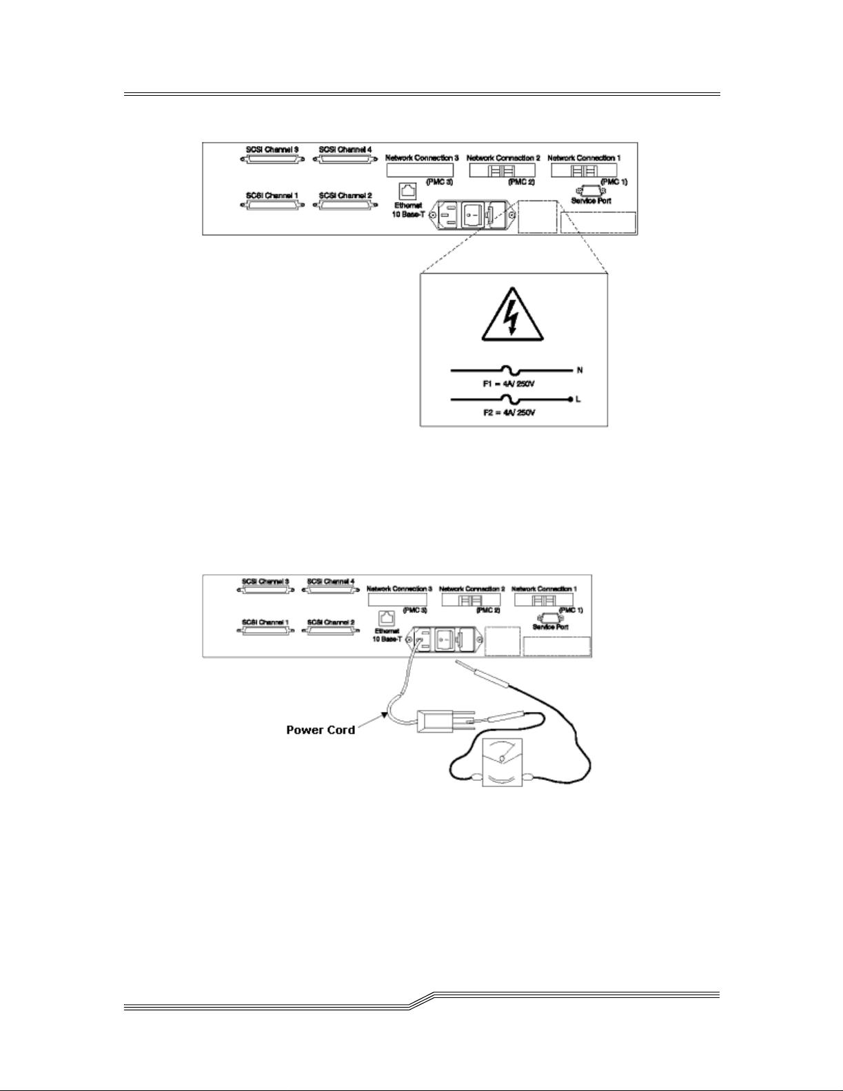
Figure 1-1: Safety Label
3. Check the voltage label on the bottom of the device to ensure it matches the
voltage at the power sou rc e.
4. Check the voltage level at the power source.
5. Check for proper grounding. See Figure 1-2.
Figure 1-2: Ground Test
Note: Always use an analog meter, never a digital meter, to perform
the ground check of the outlet. A digital meter can give the wrong
readings if ground c urrent i s present.
8
Safety Notices
Page 25

6. With the power cord connected to the ADIC Gateway, verify that there is 1.0
ohm or less resistance between the ground lug on the power cord plug and
the metal frame.
7. If the ADIC G ateway passes the test in the previous steps, connect the power
cord to the power source.
Fusing Requirements
Figure 1-3 shows the f using label.
Figure 1-3: Fusing Label
The ADIC Gateway uses double-pole / neutral fusing.
Replace these fuses with the same r ating.
The fuses ar e 4A – Time Lag / 250 V
Safety Notices
9
Page 26
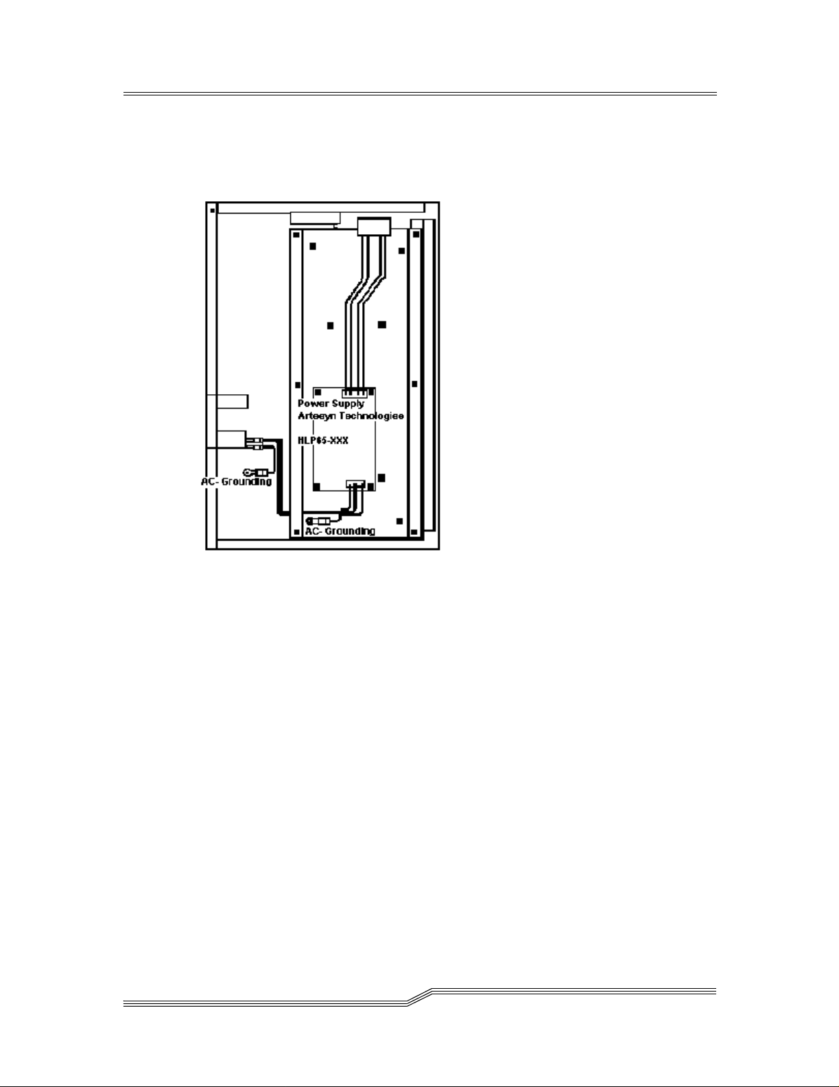
AC Grounding
Figure 1-4 shows AC grounding on the ADIC Gateway.
Figure 1-4: AC Grounding
Environmental Notices and Statements
Product Recycling
This unit contains recyclable materials. These materials should be recycled where
processing sites are available and according to local regulations.
Lithium Battery
RISK OF FIRE, EXPLOSION, OR BURNS.DO NOT SHORT CIRCUIT, CRUSH, HEAT ABOVE
100 C, INCINERATE, OR DISASSEMBLE THE BATTERY
Laser Safety
This unit may contain a single-mode or multi-mode transc eiver, both of which are
Class 1 laser products. The trans ceiver complies with IEC 825-1 and FDA 21 CFR
1040.10 and 1040.11. The transceiver must be operated under the recommende d
operating conditions .
10
EnvironmentalNoticesand Statements
Page 27

General Restrictions
The classification is valid only if the module is operated within the specified
temperature and voltage limits.The system using the module must provide power
supply protection that guarantees that the system power source will cease to
provide power if the maximum recommended operation limit or more is detected
on the +3.3 V/+5 V at the power source. The operating temperature o f the module
must be in the temperature range given in the recommended operating limits.
These l imits guarantee the laser safety.
Usage Restrictions
The optical ports of the modules must be terminated with an optical connector or
with a dust plug.
Electronic Emission Statements
This section gives the electronic emission notices or s tatements for t he United
States and other countries.
Federal Communications Commission (FCC) Statement
This equipment has been tested and found to comp ly with the limits for a Class A
digital device, pursuant to Part 15 of the FCC Rules. These limits are designed to
provide reasonable protection against harmful interference when the equipment is
operated in a commercial environment. This equipment generates, uses, and can
radiate radio frequency energy and, if not installed and used in accordance with
the instruction manual, may cause harmful interference to radio commun ications.
Operation of this eq uipment i n a residentia l area is likely to cause harmful
interference, in which case the user will be required to correct the interference at
his own expense.
Properly shielded and grounded cable s and connectors must be used in order to
meet FCC emission limits. DISC is not responsible for any radio or television
interference caused by using other than recomme nded cables and connectors or
by unauthorized changes or modifications to this equipment. Unauthorized
changes or modifications could void the user’s authority to operate the equipment.
This device c omplies with Part 15 of the FCC Rules. Operation is subject to the
following two conditions: (1) this device may not cause harmful in terference, and
(2) this device must accept any interference received, including interference that
may cause undesired operation.
Industry Canada Compliance Statement
This Class A digital apparatus complies with Canadian ICES-003.
Electronic EmissionStatements
11
Page 28

Avis de conformité à la réglementation d’Industrie Canada:Cetappareil
numérique de la classe A est conform à l a norme NMB-003 du Canada.
European Community Compliance Statement
This product is in conformity with the protection requirements of EC Council
Directive 89/336/EEC on the approximation of the laws of the Member States
relating to electromagnetic compatibility. ADIC cannot accept responsibility for
any failure to satisfy the protection requirements resulting from a nonrecommended modification of the product, including the fitting of non-ADIC option
cards.
This product has been tes ted and found to comply with the limits for Class A
Information Technology Equipment according to European Standard EN 55022.
The li m its for Class A equipment were derived for commercia l and industrial
environments to provide reasonable protection against interferenc e with licensed
communication equipment.
Attention: This is a Class A pro duct. In a domestic envi ronment, this product may
cause rad io interference in which case the user may be required to take adequate
measures.
Where shielded or special cables (for example, cables fitted with ferrites) are used
in the test to make the product comply with the limi ts:
Properly shielded and grounded cable s and connectors must be used in order to
reduce the potential f or causing i nterference to radio and TV communications and
to other ele ctrical or electronic e quipment. Such cables and connectors are
available from ADIC authorized dealers. ADIC cannot accept responsibility for any
interference caused by using other than recomme nded cables and connectors.
Japanese Voluntary Control Council for Interference (VCCI) Class
1Statement
12
Electronic Emission Statements
Page 29

Chapter 2: Introduction
This chapter describes the ADIC Gateway. It provides the following information:
•Overview
• Configura tion S upport
• Hardware Product Description and Features
• Supported Platforms
• Supported Devices
• Operating Specifications
• Agency Approvals
• Features
Overview
The ADIC Gateway is the interfac e between storage and Op en System Host
interfaces and provides Fibre Channel to SCSI connectivity.
Configuration Support
The ADIC G ateway is a self-co nfiguring product with Fibre Channel and SCSI
interface options. The ADIC Gateway can have up to four on-board UltraSCSI
channels and up to six SAN interfaces, which are configurable using plug-in cards.
Address Mapping
The ADIC Gateway maps addresses across and between these different
interfaces and preserves the persistency of the address maps across power ups
of systems, devices, and the ADIC Gateway. The ADIC Gateway supports the
attachment of up to 255 unique devices across multip le interfac es.
Interface Protocol Awareness
The ADIC Gateway processes SCSI-3 and SCSI-2 protocols for disk, tape, and
tape medium changer devices. It can report the host and devices that are attached
to its interfaces. The ADIC Gateway has the capability to manage the access
security between end points on the Fibre Channel interfa ces and the SCSI
channels.
Introduction
13
Page 30

ADIC Management Console
The ADIC Management Console offer s full c apability for remote management,
configurati on, and event notification. Each ADIC Gateway has internal Event
Logging, Event Analysis, and periodic Health Checks for predictive failure
analysis. All of these management, configuration, and notification capabilities are
accessible via standard SNMP protocol for use with major network manageme nt
applications. The ADIC Management Cons ole offers Java application softwa re for
the ADIC Gateway remote management and configuration.
Access Security Capabilities
The ADIC Gateway is aware of the hosts and devices that ar e attached to its
interfaces and provides access security between hosts and devices. Acces s
security between different hosts and devices i s a requirement for multi-initiator
SAN solutions. Using the ADIC Management Console, you can partition the SAN
for different levels of access and p erformance.
Virtual Private SAN™ Option
VPS technology enables Storage Area Networks with multiple users to share the
same connectivit y chann els or pipes to access the same or different storage
elements or resources. Therefor e, multiple virtual private connections can be
created on the same storage networking infrastructure.
VPS is a Virtual Private c onnection or channel between a storage element and the
user of that element in a Storage Area Network. Virtual Private SAN is created by
a method of Access Security that manages the access between an Initiator (user,
host, system, ..) to Target/LUN (Device, Disk or Tape, ...) and also protects and
preserves such permission.
• VPS is compl etely host independent and requires no software
components on the host.
• VPS has no interface depen dencies and supports Fibre Channel,
SCSI or any other SAN interface.
• VPS supports SAN connectivity/fan-out products such as hubs
and s witches.
• VPS is independent of the storage elements and r equires no
change in legacy or new storage devices.
An optional automatic host registration service that sends periodic host status
information to VPS is provided.
VPS is an optional software capability for the ADIC Gateway that requires a
license key to be enabled.
14
Configuration Support
Page 31

Data Mover
The ADIC G ateway can move data directly between storage devices that are
attached to it. This direct movement of data can be from disk to disk, disk to tape,
tape to disk or tape to tape. Data Mover frees-up valuable system resources on
the serv er a nd substantially increases the speed of backup and restore
operations.
Data Mover is the engine for Server-Free backup and restore and HSM
applications that support the Extended Copy Specification (ANSI T10/99-143r1).
The Data Mover capability is always available to users of the ADIC Gateway
Virtual Private Map™ Option
VPM technology enables legacy and new systems equipped with S CSI Host Bus
Adapters to access SAN devices.
• VPM allows Fibre Channel and SCSI Target devices to be
mapped to private SCSI host channels.
• VPM is completely host independent and requires no software
components on the host.
VPM is an optional software capability for the ADIC G ateway that requires a
license key to be enabled before use.
Channel Zoning
Channel Zoning is a means of managin g the access security between SAN
connections and SCSI channels on a channel by channel basis.
Channel Zoning can be used to secure access between a se rver and its storage,
segregating them, for example, from other servers and their respective storage .
The default settings allow all SAN co nnections to access all SCSI Channels.
The Channel Zoning capability is al ways available to users of the ADIC Gateway.
Hardware Product Description and Features
This section describes the capabilities of the product and outlines some of the key
features of its interfaces.
• An Intel i960RD 66 MHz I/O processor with integrated instruction
set and data caches
• Interleaved fast-page-mode (FPM) processor memory using
Hardware Product Description and Features
15
Page 32

standard 60 nanosecond FPM SIMMs for command, control, and
code execution
• Non-volatile FLASH memory for operational firmwar e , powe r on
self-test code, diagnostic functions, system utilities, persistent
configuration tables, and event log. The default configuration is 2
MB.
• VxWorksreal-time operating system (RTOS)
Fibre Channel Interfaces
Interfaces fo r host and device attachment can be configured for up to three plug-in
PCI Mezzanine Cards (PMCs). These interfaces can be configured to use singleport copper, single-port Short Wave Optical, single-port Long Wave Optical, or
dual-port Short Wave Optical Fibre Channel PMCs.
The PMCs can be replac ed in the field by the customer or by a service
representative.
T able 2-1: Fibre Channel Connections
Connection Type Connector Cable Type Speed Distance
Copper HSSDC 1.062.5 Mb/sec 30 m
Optical Short Wave Duplex SC 62.5 µ multimode 1.062.5 Mb/sec 300 m
Optical Short Wave Duplex SC 50 µ multimode 1.062.5 Mb/sec 500 m
Optical Long Wave Duplex SC 9 µ multimode 1.062.5 Mb/sec 10 km
Fibre Channel interfaces support the following Pub lic and Private Loop modes:
• Target
• Initiator
• Target and Initiator
Fibre Channel Interfaces also support the following connection options:
•Loop
• Point-to-Point
•LoopPreferred
Fibre Channel interfaces are in compliance with the following standards and
specifications:
• Private Loop (FC-PLDA, Rev. 2.1, Sept 22 , 1997) Class 3
• Public Loop (FC-FLA, Rev. 2.7, Aug 12, 1997) Class 3
• Fibre Channel-AL-2 Rev. 6.4, Aug 28, 1998
• Fibre Channel-PH Rev. 4.3, June 1, 1994
• SCSI- Fibre Channel P, Rev. 12, May 30, 1995
16
Hardware Product Description and Features
Page 33

Ultra2 SCSI I/O Interfaces
• Any or all of the thre e PCI Mezzanine Card (PMC) interfaces can
be c onfigured to use a dual-ported Ultra2/3 SCSI PMC board
instead of a Fibre PMC.
• Ultra2/3 SCSI PMCs are available as Single-Ended/Low Voltage
Differential (SE/LVD) or High Voltage Differential (HVD).
• SCSI PMCs use standard VHDCI stacked right-angle SCSI
connectors, and autonegotiate speeds of up to 80 MHz for Ultra
SCSI-2 and 160 MHz for Ultra SCSI-3.
• The cable lengths can be as long as 25 meters with HVD
interfaces and 12 meters for LVD/SE interfaces.
The SCSI interfaces are compliant with the following SCSI specifications:
• ANSI T10/1071D Re v. 6, SCSI-3 Fast-20
• ANSI T10/375D Rev. 10t, SCSI-2
• ANSI T10/1142D Rev 20b , SCSI-3 Parallel Interface-2
Ultra SCSI I/O Modu les
The key featur es and capabilities of the ADIC Gateway’s on-board Ultra SCSI I/O
modules are listed below.
• Up to four Ultra Wide SCSI channels--Single-Ended (SE), high
voltage differential (HVD), and/or Low Voltage Differential (LVD)-with internaltermination arepossible.
• SCSI channels have automatic speed and width negotiation
capability for wide or narrow bus widths and Standard, Fast, or
Ultra speeds. These parameters can be viewed from the ADIC
Management Console.
• You can disable the termi nation on SCSI channels through the
installation of a jumper or from the ADIC Management Console.
• The SCSI ID of each channel is set by default to 7 and can be
changed from the ADIC Managem ent Console.
• Each SCSI channel supports up to 15 SCSI target IDs and up to
32 LUNs per ID (subjectto an overalltotal of 256 devices). The
ADIC Gateway uses one LUN for command and control so tha t
the remaining 255 LUNs are available for SCSIdevices.For
each Fibre Channel interface, the ADIC Gateway occupies one
Fibre Channel ID and all SCSI target devices are available as
LUNs on the same Fibre Channel ID.
• The unitco mes with SCSI-3 68-pin jackscrew externalconnectors
for maximum mechanical reliabi lity.
• Cablelengthscanbeaslongas25meterswithSCSIHVD
interfaces.
Hardware Product Description and Features
17
Page 34

Ethernet
The 10/100 B ase-T Ethernet port has an RJ-45 c onnector for out-of-band
management. It can be connected to a networ k hub using an unshielded twistedpair Ethernet cable. The Ethernet port complies with the IEEE 802.3 specification.
Service Port
The service port is an RS-232 connection with a 9-pin D-shell connector (DTE). It
is compatible with serial po rts on personal computers.
The service port is used for local service and diagnostics when you use a terminal
session to the shell interface.
The service port is configured at 19,20 0 Baud, 8 data bits, no parity and XON/
XOFF. It connects to the host serial port with a 9-pin to 9-pin null modem cable.
Enclosure
The enclosure is des igned for strength, durability, and electromagnetic and r adio
frequency interference (EMI/RFI) immunity.
The external dimensions are:
• 2U ( 3.5”) hi gh
• 11” deep
• 16.73” (standard 19” rack) wide
It is available with standard 19-inch Rack Mount or Desk Top configuration kits.
The enclosure has two ball bearing cooling fans that draw air in through the si de
of the enclosure. The exhaust is on the opposite side.
Two temperature switches monitor the internal temperature of the enclosure. One
switch in dicates a temperature warning at 60°C and the other indicates a
temperature alarm at 70°C.
The enclosure has an Enclosure Monitor Register facility. It monitors the status
and health of all components of the enclosure and reports it to the ADIC
Management Console. Status is also displayed on the front panel LED indicators.
Power Supply Unit
The power supply is an auto-sensing universal power suppl y nominally supporting
power be tween 100 -127 VAC and 200-240 VAC, at a frequency of 50/60 Hz, with
a maximum input power rating of 90W.
18
Hardware Product Description and Features
Page 35

It has the highest reliability and mean time between failure (MTBF) numbers and
is manufactured by a leading powersupply company with excellentfield reliability
results in the industry.
It has a standard integrated power entry, on/off switch, and fuse holder. It uses
two250V4Atimelagfuses.
The power supply status is monitored as part of the Enclosure Monitor Register
and is reported by the front panel LED, and to the ADIC Management Console.
LED Indicators
On the front panel there are LEDs that provide a vi sual indication of the status and
activity of the ADIC Gateway and its interfaces. Wh en the ADIC Gateway is first
turned on, some of the LEDs will be on and others will flash while it is booting.
Starting from the left of the fron t panel, the followin g list describes how to interpret
the LED signals after the ADIC Gateway has finished booting.
Figure 2-1: LEDs on Front Panel
• SAN Connections
A group of six green LEDs that indicate Status and Activity on the SAN
interfaces for each of the three PMC slots.
If a single-port Fibre Channel card is installed, the Status LED will be
ON when the port is up and is connected to a live Fibre Channel
device. The Activity LED will flash when there is activity on the SAN
interface.
If a dual-port Fibre Channel card is installed, the Status LED will be
ON when both ports are up and are connected to live Fibre Channel
devices. The Status LED will flash once per second when the num erically lower port is down and the numerically higher port is up. The
Status LED will flash every two seconds when the numerically higher
port is down and the numerically higher port is up. The Activity LED
will flash when there is activity on one or both SAN interfac es.
• SCSI Channels
A group of four green LEDs. OneLED for each of the four SCSI chan-
Hardware Product Description and Features
19
Page 36

nels. A flashing Activity LED indicates activity on a SCSI Channel.
• Ethernet
A group of three LEDs (two green, one amber) indicate the Link,
Transmit, and Collision statuses of the Ether net Port network connection.
• Temperature
A group of two amber LEDs indicate Temperature Warning and Tem-
perature Alarm. Normally the LEDs are OFF indicating temperature
is within acceptable limits.
•Power
A green LED indicates the status of the main power supply. Normally
the Power LED is ON indicating that the power supply is ON and output voltage is within acceptable limits.
•RDY
A green RDY LED indicates a status of ready. Norm ally the RDY LED
flashes once per second i ndicating good health. The RDY LED
begins flashing after the ADIC G ateway has finished booting. If the
LED is ON for more than a few seconds it means there is a problem.
If the LED is OFF (and the ADIC Gateway is turned on) it means
there is a problem. If the LED is flashing rapidly (and you have not
selected “Identify Gateway” via the ADIC Management Console), it
means there is a problem.
Supported Platforms
The ADIC Gateway is a platform-independent product. You can connect a host to
the ADIC Gateway after you have installed the appropriate host bus adapter and
drivers. You can also co nnect host systems with different operating systems to
the ADIC Gateway through Fibre Channe l.
For a current list of su pported platforms, configurations, and hos t bus adapters,
visit “Service and Support” at www.adic.com, or call the ADIC Technical
Assistance Center at 1-800-827-3822.
Supported Devices
The architecture and implementation of the ADIC Gateway software has full
SCSI-2 and S CSI-3 target and init iator support. The ADIC Gateway has support
for disk, tape, and medium changer devices. The product suppor ts all these
devices with the same ADIC Gateway firmware. Multiple target device type drivers
coexist to support different device types.
20
Supported Platforms
Page 37

For a current list of supported devices, see the Web site and technical support
contact information, visit “Service and S upport” at www.adic.com, or call the ADIC
Technical Assistance Center at 1-800-827-3822.
Operating Specifications
This section contains the physical, electrical, and environmental specifications for
the product.
Installation Options
• Desk top wi th four rubb er feet
• Rack mount with two rack mount brackets
Physical Dimensions
• Height: 3.5” (2U)
• Width: 16.73”(Standard 19” rack)
• Depth: 11”
Operating Environment
POWER ON,OPERATING EXTREMES
• Temperature: 10°C to 4 0°C (50°F to 104°F)
• Relative Humidity: 8% to 80%
• WetBulb: 27°C (80°F)
OWER ON,RECOMMENDED OPERATING POINTS
P
TEMPERATURE
• 22°C (72°F) Relative Humidity: 45%
P
OWER ON,RECOMMENDED OPERATING RANGES
• Temperature: 22°C to 2 5°C (68°F to 77°F)
• Relative Humidity: 40% to 50%
P
OWER OFF
• Temperature: 5°C to 45°C (41°F to 113°F)
• Relative Humidity: 8% to 80%
• WetBulb: 27°C (80°F)
Operating Specifications
21
Page 38

STORAGE
• Temperature: 0°C to 60°C (32° F to 1 40° F)
• Relative Humidity: 8% to 80%
• WetBulb: 29°C (84.2°F)
Power Consumption
The power consumption of this product depends on the number and type of
installed interface options. The following numbers are line power consumption
values for a fully co nfigured product. The maximum line power co nsumption is 90
watts in activ e mode. Typical line power consumption is 60 watts in active mode.
AC Power Requirement
100 -127 VAC and 200-240 VAC, at a frequency of 50/60 Hz
Agency Approvals
The SAN Router is tested and conforms to the following agency approval
requirements:
• Class 1 laser product (with Fibre Channel optical option only)
• Complies with FDA 21 CFR 1040.10 and 1040.11
• CSA Mark with an NRTL/C indicator
• The N RTL/C indic ator a djacent to the CSA Mark signifies that the
product has been evaluated to the applicable ANSI/UL and CS A
standards, for use in the U.S and Canada.
• FCC Rules, Part 15, Class A
• EMC directive 89/336/EEC (CE Mark)
• EN55022, Class A
• EN61000- 4-2 ENV50140
• Australian EMC Framewor k (C-Tick mark)
• AS/NZS 3548:1994, Class A
•VCCI,Class1
22
Introduction to the ADIC Management Console
The D irector uses a combination of industry-standard Simple Network
Management Protocol (SNMP) requests and a method or technology known as
SCSI over T CP, which encapsulates SCSI commands and/or data in TCP
packets.
Introductionto the ADIC Management Console
Page 39

Client/Server Model
Figure 2-2: ADIC Management Console Application Model
Agent
Each ADIC Gateway is a stand-alone, S NMP-manageable host. The ADIC
Management Console uses SNMP as the primary method of communication with
the agents. This allows you to set and retrieve information that controls the
operation of the agent. It also provides alerts (traps) when an event has occurred
that requires intervention. The SCSI/TCP component allows you to update
firmware on the ADIC Gateways and target devices and manipulate device
operating parameters. The agent component is embedded in the operating
software of the ADIC Gateway.
Server
The Server component is a Java application that runs on a host computer system
(see “Installation Requirements”). The server is responsible for maintaining
communication with the managed agents, and acts as an interm ediary between
the agent running on the ADIC Gateway and multiple Clients. It provides security
features by maintaining account names and passwords on behalf of the Client
application. By keeping track of different Client views, a user can recall a saved
view from any Client.
The Server c oordinates the requests from multiple clients to manage multiple
ADIC Gateways. Communication between the Server and the agents is carried
out either by SNMP or SC SI/TCP, as required. Specifically, the Java Management
Application Programming Interface (JMAPI) is used where possible to provide an
industry standard and transportable interface. All communications between the
Clients and the Server is implemented using the J ava Remote Method Invocation
(RMI), a form of remote procedu re call (RPC).
Introduction to the ADIC Management Console
23
Page 40

The Server is written to be both transportable and efficient. Multiple Clients can
share data the Server already knows about rather than having to request the data
again. In additi on, the Server receives all traps from the agents and forwards them
to the Clients that have registered to receive them.
Client
The Client is a Java application. One or more Clients connect to a Server in order
to manage the ADIC Gateways. The Client operates from any c ompatible
computer, as long as a TCP/IP connection is established to the Server
component. This allows for di al-in configurations using Point-to-Point Protocol
(PPP), intranet, or Internet access (where allowed by l ocal network policy and
firewall configurati ons). If the client is started on the same host as the server, a
connection will automatically be established.
The Client is the application that provides the userinterface and allows viewing
and manipulating of all ADIC Gateways and device parameters. Each Client can
be co nfigured by the individual user to show only the ADIC Gateways of interest.
This means that one Cl ient can monitor one set of ADIC Gateway s and othe r
managers can be responsible for totally di fferent ADIC Gateways, without
interfering with each other.
The C lient uses Java RMI calls to communicate with the server, and SCSI over
TCP to communicate directly to the A DIC Gateways for some operations.
Features
SNMP
SNMP community strings serve to group network devices into logical collections
for management purposes . The community strings on the Serv er must match
those on the ADIC Gateway you wish to manage.
There are three different strings defined for the ADIC Management Console:
Read for querying the ADIC Gateway.
Write for controlling the ADIC Gateway.
Trap for receiving event messages from the ADIC Gateway
The ADIC Gateway can maintain 32 Read and W rite community strings and 1
Trap community string.
24
Features
Page 41

SNMP Community Support
A set of commands is provided for manipulating the SNMP Community strings.
These s trings act as passw ords for authenticating requests made from managing
applications such as the ADIC M anagement Console.
There are three different communities defined: Read (allows “Gets” only), Write
(allows “Sets”, i.e., changes to be made) and Trap (defines the Community string
that a trap recipient will allow). In order for a managing application to view or
control an SNMP agent (such as the ADIC Gateway), it must provide the correct
community string for eac h request. The A DIC Gateway allows up to 32 community
strings for each of the Read and Write communities. There is only a single Trap
community string.
Security
Logging on to a server is required to manage the ADIC Gateway via the ADIC
Management Cons ole application. Two levels of privilege control what type of
access is allowed:
Administrator
Allows full access, including changing parameters
User
Allows viewing of data and parameters onl y
Service Port access is managed with User accounts created via telnet or the serial
interface on the ADIC Gateway
SAN Access Control
Access control features include Channel Zoning, opti onal Virtual Private SAN
(VPS™) and optional Virtual Pri vate Map (VPM™).
Channel Zoning allows select ed SCSI channels to be available to selected SAN
connections.
The VPS option requires a software license key to enable the Initiator-Target/LUN
access control feature. VPS manages access permission between any host
attached to a SAN connection and any storage element attached to the ADIC
Gateway. This includes storage devices attached to any SCSI Channel and
storage devices attached to any other S AN Connection on the ADIC Gateway.
The VPM option requires a software license key to enab le target devices on any
channel to be mapped to any SCSI host c hannel.
Features
25
Page 42

Host Registration Service
The Host Registration Service is software that installs on the host from the CDROM or it can be downloaded from the website. It simplifies VPS configuration for
the system administrator. It removes the burden of physically tracing each
connection to correlate the Fibre Channel HBA World Wide Name (WWN) with a
specific host.
The registration service installs on most host pla tforms and it provides the ADIC
Gateway with periodic host status information including the host name, hos t type
and ty pe of HBA installed. Host information is sent over the host Fibre Channel
connection to the ADIC Gateway.
Once installed, the service runs automatically and does not req uire further system
administra tor interaction. From the ADIC Management Console, you can see the
Fibre Channel that the host is connected to and you can tell whether the host is on
or offline.
Saved Views
Each user can store their own preferred views on the server. Loading a previous
view automatically connects the user to one or m ore ADIC Gateway in a single
step rather than specifying connections to ADIC Gateways individually. Because
they are stored on the server, the same views are available to th e user from any
client.
Network Discovery
Network discovery a llows y o u to locate any ADIC Gateway based on network
addresses and network masks. This allows m anagement of an AD IC Gateway
without knowing the specific Internet Protocol (IP) addres s beforehand.
Alternatively, the IP address (or name, if it can be resolved through DNS) of an
ADIC Gateway can be entered directly for instant access.
Configuration Options
You can set up an ADIC Ga teway with a number of non-default parameters,
channel settings, and event manage ment variables.
Software Updates
You canupdate the ADIC Gateway firmware from the client. You can also send
device micro-code to individual target devices as a means to update their
firmware.
26
Features
Page 43

Event Logging
You can retrieve and view the ADIC Gateway event logs in a table. Filtering based
upon the significance of events simplifies fault isolation.
Health Checks
Instantaneous and periodic health checks allow monitoring of each SAN Gateway
and devices attached to it. The level and intervalof the healthcheck is selectable
to obtain greater confidence or minimize the impact on system performance.
Views
Two different viewing modes are available.
Tree view shows all available ADIC Gateways and can be expanded to show
greater levels of de tail.
Front panel view shows the status of the LED indicators for a selected ADIC
Gateway.
Heartbeat
Each component of the ADIC Management Console monitors the co mponents
with which it communicates to ensure continuity of service. If the ADIC Gateway is
no longer available, the server component notifies monitoring clients
Features
27
Page 44

28
Features
Page 45

Chapter 3: Installation
This section c overs installation of the ADIC Gateway, SCSI devices, and the host
adapter. Before you or your service representative installs the ADIC Gateway you
must perform the steps in the Pre-installation checklist.
Note: Ensure SCSI device interfaces matc h the interfaces of the attached S CSI
devices (SE/LVD or HVD).
Instructions on how to install the product is divided into three sections:
Pre-installation Checklist:
Before you or the service representative installs the AD IC Gateway
check the items on the pre-installation checklist.
Installation Checklist:
The installation checklist has instructions on how to install the ADIC
Gateway.Youmayhavetheoptionofhavingaservicerepresentative
perform this portion of the installation for you.
Post-installation Checklist:
After you or the service representative installs the ADIC Gateway, fol-
low the post-installation checklist to complete the installation.
Pre-installation Checklist
It is important that the items in this checklist are verified before you begin the
installation of the ADIC Gateway. This ensures a successful i nstallation of the
product.
Table 3-1: P re-Installation Steps
Step User Action or Decision Comments and References
1
• Desktop Install
• Rac k Mount Install
Decide whether the ADIC Gatewa y is to
be installed on a desktop or rack
mounted. See “Desktop Configuration”
on page 38 or “Rack Mount
Configuration” on page 38
Installation
29
Page 46

Table 3-1: P re-Installation Steps
Step User Action or Decision Comments and References
2
Verify host platform OS,
required Service Pack
installed
For example: Windows NT
For a current list of supported platforms
required host platform code upda tes and
information on how to obtain them, ADIC
Gateway
4.0,Service Pack 6a (or
later)
3
Verify required Fibre
Channel Host Bus Adapter,
HBA BIOS and device
driver procured,installed
For a list of supported HBAs and the
required BIOS and device driver, visit
“Service and Support” at www.adic.com,
or call the ADIC Technical Assistance
Center at 1-800-827-3822
See also “Host Adapter Setup” on
page 44
4
If you will be connecting
more than one host to the
See “Setting up Access Control” on
page 58
ADIC Gateway and you
want to use the Virtual
Private SAN or Virtual
Private Map access
options, be sure you ha ve
the necessary licenses
30
5
IfyouareusingVirtual
Private SAN or Virtual
Private Map, install the
For Windows NT/Win dows 2000, see
“Installing the SAN Explorer and Host
Registration Service” on page 44
Host Registration Service
on the hosts that will be
connected to the ADIC
Gateway
6
Ensure that all host Fibre
Channel cables
• Hav e been ordered with
the product or have been
preinstalled and chec k ed
• A r e marked with:
For Solaris, AIX and other platforms, see
“Installing the Host Registration Service”
on page 44
Refer to the HBA Specification provided
with yourHBA and “Hardware Product
Description and Features” on page 15
-Host system
identifier
- ADIC Gateway
system identifier
Pre-installation Checklist
Page 47

Table 3-1: P re-Installation Steps
Step User Action or Decision Comments and References
7
Ensure that SCSI disk or
tape system installation
has been completed.
• For tape attach, tape
device driver installed or
updated
• Mark both ends of each
SCSI cable with
Usually done by you or a service
representative during target device
installation
-Target ID and
channel number
-ADIC Gateway ID
and channel number
8
Decide on network
parameters.
Ethernetport configuration
decisions:
• Static IP
address____________
• Netmask (if
required)_________
• Us er-def ined
Gateway
(optional)_______________
name
ADIC
Obtain the network parameters from your
network administrator.
Attention:Use of incorrect network
parameters can cause problems on the
Ethernet network.
The default network name is A DIC
Gateway.Ifyouchooseadifferentname,
it becomes the prompt displayed on the
service terminal. Choosi n g a different
name may be useful if you have more
than one ADIC Gateway
If the ADIC Gateway is not
on the same TCP/IP
subnet as the server*,
assign the default network
gateway address and/or
route tableentries.
_____________________
9
Pre-installation Checklist
Attention: Save this
configuration infor mation
for future reference.
Run the Et hernet cable
from the ADIC
Management Console
server to the network hub
None
31
Page 48

Table 3-1: P re-Installation Steps
Step User Action or Decision Comments and References
10
* Server in this context means the computer used for the ADIC Management
Console server application
Run the Et hernet cable
from the network hub to the
ADIC Gateway
None
Installation Checklist
The installation checklis t has instructions on how to install the ADIC Gateway with
SCSI attached storage and FC attached hosts. You may have the option of having
a serv ice representative perform this portion of the installation f or you.
Table 3-2: Installation Steps
Step User Action or Decision Comments and References
1
2
Acquire information for
ADIC Gateway installation
Unpack the ADIC
Gateway.
Check the components
against the s hip group lis t
Refer to Step 8 in Table 3-1: “PreInstallation Steps”
32
3
4
If desktop, install four
rubber feet (ADIC
Gateway supplied parts)
If rack mount , install rack
mounting (ADIC Gateway
supplied parts)
Connect the Power Cord
to the SAN Gateway
If desktop, go to “Desktop Configuration”
on page 38.
If rack mount, go to “Rack Mount
Configur ation” on page 38.
Go to “Connecting Power” on page 43.
Installation Checklist
Page 49

Table 3-2: Installation Steps
5
Connect the service
terminal to the Service
See “Connecting to the Service Port” on
page 217.
Port and start up a
terminal emulation session
Step User Action or Decision Comments and References
6
Turn on the ADIC
Gateway and observe the
startup messages on the
service terminal
Look for “done executing startup script”
message (See “Startup Message
Reference” on page 315)
Within one minute, the Ready LED
should start flashing once per second.
If the “done executing startup script”
message is not seen or the Ready LED
is not flashing as expected, go to “Start
MAP” on page 157
7
Issue the
initializeBox
commandfrom the se rvice
terminal. After issuing this
command, the ADIC
Gateway will reboot
See“Service Port Command Reference”
on page 223.
Attention: This command will erase all
configuration information. It should be
used only during initial ADIC Gateway
installation
automatically.
8
9
Installation Checklist
If you purchased licenses
for the Data Mover
Module, VPS, or VP M, you
should activate them now
by typing
sncFeatureEnable
vpmFeatureEnable
vpsFeatureEnable
Look for the “done
executing startup script”
messageontheservice
terminal, then turn off the
ADIC Gateway
see Appendix B: S ervice Port Command
Reference
None
33
Page 50

Table 3-2: Installation Steps
10
The SCSI disk or tape
None
subsystems must be
installed and verified
before the ADIC Gateway
installation can continue
11
Connect the SCSI cables
from the target devices to
Go to “Attaching SCSI Devices” on
page 39
the ADIC Gateway.
Turn on the SCSI target
devices
Step User Action or Decision Comments and References
12
Turn on the ADIC
Gateway
Within one minute, the Ready LED
should start flashing once per second
and the “done executing startup script”
message should be displayed on the
service terminal
13
Issue the targets
commandfrom the se rvice
terminal.
See “Appendix B: Service Port
Command Reference”.
If all attached SCSI targetsare not
shown, go to “SCSI MAP” on page 171
13
14
• Conf igure the Ethernet
Port (Host Name, Address,
Routes, Enable Ethernet,
reboot).
• Connec t the Ethe rnet
cable from the network hub
to the
ADIC Gateway
• Obs erv e Ethernet Link
LED
Issue hostTypeShow
commandfrom the se rvice
terminal to vi ew host type
settings for the Fib re
Channel ports.
If the hosts that will be
connected are not the type
shown, issue setHost
commandfrom the se rvice
terminal to set the host
type for each Fibre
Channel port
Configure the Ethernet Port using
information from Step 8, Table 3- 1: “Pre-
Installation Steps” on page 29.
Go to“ADIC Gateway Network Setup” on
page 49.
If the Eth ernet L ink LED is not on, go to
“Ethernet MAP” on page 187
See ““setHost [port],“OS”” on page 270”.
If the Virtual Private SAN access control
option will be installed, V PS will
configure the host type for each host and
override the Fibre Channel port host type
settings
34
Installation Checklist
Page 51

Table 3-2: Installation Steps
15
Power down the FC
host(s).
Connect the FC cables
from the FC HBA(s) to the
ADIC Gateway.
Power up the FC host(s)
If SAN Connection Status LED for the
attached host(s) is not on, check FC
cables. You may have to change the
polarity of the FC cables. If problem
persists,go to “Fibre Channel MAP” on
page 178
Step User Action or Decision Comments and References
16
Issue fcShow command
from the service terminal
to show the status of each
FC interfacethat is
installed and connected.
Issue fcShowDevs
commandfrom the se rvice
terminalto show SCSI
target d evices that are
See“Service Port Command Reference”
on page 223.
In the output of the fcShow command,
lookfortheFirmwareStatecolumn.If the
word Ready does not appear, go to
“Fibre Channel MAP” on page178.
Check to see that all SCSI target devices
are seen by each FC interface. If not, go
to “SCSI MAP” on page 171
connected as seen by the
Fibre Channel interface
17
18
Verify all target devices
are available to the host
system(s)
Perform steps in Table 33, on page 36 “PostInstallation Checklis t”
Use appropriate host system utilities for
disk and tape. If all devices are NOT
available, reboot host system(s) and
check again. If problem persists, go to
“Start MAP” on page 157
In SAN Configuration, twospecific areas
require understanding an d attention:
• Access Con trol
• S av e Configuration
For more information on these, see
“Understanding SAN Configurations” on
page 53
Installation Checklist
35
Page 52

Post-installation Checklist
Perform the actions listed in Table 3 after you or your service representative have
completed the installation steps.
Table 3-3: Post-Installation Steps
Step Customer Actions Comments and References
1
2
3
4
Install the ADIC
Management Console
software.
For an updated list of
supported systems, visit
“Service and Support” at
www.adic.com, or call the
ADICTechnicalAssistance
Center at 1- 800-827-3822.
Ensurethatthedesignated
system has access t o the
same E thernet subnet as
the ADIC Gateway
Start-up the ADIC
Management Console
server
Start-up the ADIC
Management Console
client:
• Connec t to the server (if
it does not find the server
running on the same system)
• Log on
• Add new a dmi nistrator
account and password. This
removes the default account
• Log off and log on using
thenew administrator
account
See “Install the ADIC Management
Console Software” on page 46
The designated system will be used as
the central point for mo nitoring and
controlling ADIC Gateways
Consult your network adminis trator
See “Startup and Configuration” on
page 47
Connect using the name or IP address of
the designated server system.
See “Startup and Configuration” on
page 47
36
5
6
From the client, connect to
the des ired ADIC
Gateways
Save your user/
administra tor view
See “Connect SAN Gateway” on page 80
See “Save Current View as” on page 66
Post-installation Checklist
Page 53

Table 3-3: Post-Installation Steps
7
8
9
10
11
If later firmware is
available, perform the
following for each ADIC
Gateway:
• Updat e firmware
• Restart
If you chose an Access
ControloptioninStep8of
Table 3-1: “Pre-Installation
Steps” on page 29, Use
the ADIC Management
Console to enable Access
Control
At this time, you MUST
save the ADIC Gateway
configuration
Becomefamiliar with using
the ADIC Management
Console
You must use the ADIC
Management Console to
monitor and maintain your
Storage Area Network.
If a trap/event is reported
by the ADIC Management
Console, check the
reported event code,then
see and perform t he
recommended action
See “Controls Menu Group” on page 94
To obtain information about firmware
updates, visit “Service and Support” at
www.adic.com, or call the ADIC Technical
Assistance Center at 1-800-827-3822
See “Access Options” on page 97
See “Save SAN Gateway Configuration”
on page 90
See “Using the ADIC Management
Console” on page 63
See “Remote Event Notification” on
page 307
Note: We highly recommend that you save y our ADIC Gateway configuration
periodically. You MUST save your configuration if you add or remove devices,
or if you make changes to access control or other operating parameter settings
ADIC Gateway Setup
Placing the ADIC Gateway
Whether installed in a rack or on a desk, the ADIC Gateway must be situated with
a minimum of one inch of clearance on either side to allow adequate airflow
ADIC Gateway Setup
37
Page 54

through the box. The venti lation holes in each side of the unit must never be
blocked.
There are no spacing requirements a bove or below the unit.
Desktop Configuration
The ADIC Gateway is shipped with four rubber feet that should be used when the
ADIC Gateway is placed on a desktop or other flat surface. Perform the following
to install the rubber feet.
1. Turn the ADIC Gateway upside down.
2. Remove the backing from the a dhesive side. Apply to each of the corners on
the bottom of the ADIC Gateway approximately ¼-inch from each edge. See
Figure 3-1.
38
Figure 3-1: Installing the Rubber Fe et for Desktop Use
Rack Mount Configuration
The ADIC Gateway rack mount kit (included) contains brackets, screws, and
washers that enable it to be mounted in a standard rack. See Figure 3-2. If y our
rack does not have threaded rail s, you will need to provide clipnuts to complete
the installation. The rack screws that are provided are threaded 10-32. If this does
not match the threaded rails, you will need to provide other screws to complete
the installation. To install into a rack, perform the following:
1. Using one of the brackets, locate the hole s you will be using on each side rail
of the rack. Insert the clipnuts (A) if the rails are not threaded.
ADICGateway Setup
Page 55

2. Attach a bracket (D) to each side of the ADIC Gateway using the small screws
(A) p rovided with the brackets.
3. Place a washer on each screw (C). Hold the ADIC Gateway in the rack and
secure with four screws.
Figure 3-2: Installation I nto a Rack
When mounted in an enclos ed rack, provision must be made to exchange 24 CFM
of air between the interior of the rack an d the room environment for each ADIC
Gateway in stalled.
Attaching SCSI Devices
SCSI devices are attached to any o f the SCSI connectors on the rear of the ADIC
Gateway. The device types and s peeds, as well as cabling, target IDs, and
termination are discussed below. High quality cables with the correct latches or
screws must be used at all times to ensure reliable connections. Cables are not
provided with the ADIC Gateway.
ADIC Gateway Setup
Note: Ensure that you read this section before you attach any devices
to the ADIC Gateway. A summary table appears at the end of this
discussion.
39
Page 56

Maximum Number of LUNS
The ADIC Gateway supports up to 255 LUNS.
Attention: Do not attach more than 255 LUNS to the ADIC Gateway. Exceeding
the 255 LUN limit will result in unrel iable behavior.
Transfer Rates: Ultra, Fast, and Asynchronous
The SCSI protocol defines two methods of data transfer: synchronou s and
asynchronous. Asynchronous transfers may run as fast as 5 MHz, while
synchronous trans fers may run as fast as 160 MHz (Ultra3).
The rate of transfer is negotiated between a SCSI initiator, such as the ADIC
Gateway, and each target. For each target device identifie d during a bus scan, the
ADIC Ga teway will request a transfer rate at the fast est transfer rate supported by
the ADIC Gateway. The target will then reply with the maximum transfer rate it will
support.
Note: In general, devices that are capable of running at Ultra2/3 speeds should
not be mixed on a bus with slower devices, since the bus speed will be set to
match the slowest device on the bus.
Wide and Narrow SCSI Buses
A SCSI bus may be either narrow (8 bit) or wide (16 bit). The ADIC Gateway SCSI
buses are all wide, but may be connected to narrow devices with the correct cable
adapters.
Although it is possible to mix narrow and wide devices on a single SCSI bus, this
configurati on is not recommended. If any of the devices supports Ultra2/3 speeds,
then a mix of narrow and wide devices is prohibited.
In order for the ADIC Gateway to locate and communicate with the devic es, each
device on the SCSI bus must be assigned a unique target ID. On a wide (16 bit)
SCSIbus, the SCSIstandardallowsfor atotalof 16targetIDs.On a narrow(8 bit)
SCSI bus, the SCSI standard al lows for a total of 8 target IDs. There are no
requirements about the ordering or position of the target IDs on the SCSI bus. The
only requirement is that there be no duplicate target IDs. By default, the ADIC
Gateway uses ID 7. Thus, peripheral devices may be assigned IDs 0 through 6
and 8 through 15, typically selected by a switch or jum pers. T hese settings may
be changed.
Attention: Make sure you do not assign more than one device on a
bus to the same target ID. This will prevent that bus from working
properly.
40
ADICGateway Setup
Page 57

The SCSI protocol also defines a prior ity-based arbitration method, based on the
target ID of the device attaching to the bus. The SCSI ID priority order is, from
highesttolowest,7,6,5,4,3,2,1,0,15,14,13,12,11,10,9,8.
Table of SCSI Terminology and Limitations
The following table(look for updates at http://www.scsita.org/) defines the number
of devices supported, based on the negotiated transfer type. When reviewing the
limitations of a bus, the capabilities of the fastest devices must be considered. The
bus length indicates total SCSI bus length, including any internal device cables,
rather than the length between any two devices.
Table 3-4: SCSI Trade Association Terminology
Endorsed
Terminology
for SCSIParallel
Interface
Technology
SCSI 1 (2)
Fast SCSI ( 2)
Fast Wide SCSI
(2)
Ultra SCSI (2)
Ultra SCSI (2)
Wide Ultra SCSI
Wide Ultra SCSI
Wide Ultra SCSI
Max.Bus
Speed,
MBytes/
Bus Width,
Bits
Max. Bu s Lengths,
in Meters (1)
Sec
SE HVD LVD
5 8 6 (3) 25 8
10 8 3 (3) 25 8
20 16 3 (3) 25 16
20 8 1.5 (3) 25 8
20 8 3 - - 4
40 16 - (3) 25 16
40 16 1.5 - - 8
40 16 3 - - 4
Max.
Devices
Ultra2 SCSI (2,4)
Wide Ultra2 SCSI
(4)
Ultra3SCSI or Ultra
160
Ultra320
ADIC Gateway Setup
40 8 (4) 12 25 8
80 16 (4) 12 25 16
160 16 (4) (5) 12 16
(6)
320 16 (4) (5) 12 16
41
Page 58

Notes:
1. The listed maximum bus lengths may be exc eeded in Point-to-Point and engineered applications.
2. Use of the word "Narrow", preceding SCSI, Ultra SCSI, or Ul tra2 SCSI is
optional.
3. Low Voltage Differential (LVD) was not defined in the original SCSI standards
for this speed. If all devices on the bus support LVD, then 12-meters operation
is possible at this speed. However, if any device on the bus is singled-ended
only, then the entire bus switches to single-ended mode and the distances in
the single-ended column apply.
4. Si ngle-ended is not defined for speeds beyond Ultra.
5. HVD (High Voltage Differential) is not defined for speeds beyond Ultra2.
6. After Ultra2 all new speeds are wide only.
SCSI Bus Termination
Each end of a SCSI bus must be terminated correctly. The ADIC Gateway
provides termination on each of its buses. The terminator s can be disabled using
a jum per on the ADIC Gateway motherboard. They c an als o be enabled or
disabled from the ADIC Management Console. Each interface has a separate
control for t he terminators.
42
Attention: Improper SCSI bus termination may result i n exce ssi ve err ors on the
SCSI bus, and may lead to data corruption or the inability to communicate with
target de vices.
The ADIC Gateway provides termination power on all SCSI buses for external
terminators.
Many SCSI target devices have internal terminators. It is imperative that the
terminators be disabled for all devi ces EXCEPT those at the physica l ends of the
SCSI bus.
Problems on the SCSI Bus
When A SCSI bus fails to operate correctly, it is most often caused by incorrect
connections to the SCSI bus. Common problems include:
• Missing terminat or at the end of a SCSI bus: Check that an
external termina tor is attached or that the end device has termination enabled.
• Excessive term ination: Checkthatalldevices otherthanthe end
ADICGateway Setup
Page 59

devices have termination disabled.
• Multiple devices at the same ID: If two or more devices are
configured at the same SCSI ID , only one of those devices will
be s een by the ADIC Gateway, and data transfers to that devi ce
will be unreliable. Check that only one device is set to each ID.
• Target device set to initiator’sID:If a target device is set to the
same ID as the ADIC Gateway (ID 7), the bus will be unstable
and targets will not be identified. Check that no target devices
are set to ID 7, or if one must be set to 7, change the ADIC Gateway Initiator ID.
• Bent pins in a SCSI connector: The pins in the SCSI connectors
are somewhat fragile. Inspect each connector to find pins that
were bent when the connector was attached. Re place any cables
with bent pins.
• Improper device type: A DE device on an SE bus or an SE
device on a DE bus will cause the bus to be unusable.
• Improper terminator type: ADEterminatoronanSEbusoran
SE terminator on a DE bus will cause the bus to be unusable.
• Inadequate cables: Older cables may not be suitable for running
at Ultra speeds. Be sure all cables are rated for Ultra.
• Mixed cable types: If a SCSI bus has both round cables and flat
ribbon cables, it may suffer problem s when running at Ultra
speeds. Use the same cable type consistently for all segments of
the SCSI bus.
• Unshieldedcables:An unshielded SCSI cable us ed external to a
cabinet may cause reliability problems,due to interference from
other electrical devices. Use only shielded cables.
Connecting Power
The ADIC Gateway must be co nnected to AC Power with a voltage of 100 to 127
or 200 to 240 volts, at a frequency of 50 to 60 Hz. A power switch is located next
to the power connector on the rear panel of the ADIC Gateway.
The ADIC Gateway uses two 250 V, 4 amp Time Lag fuses. They are located in
the fuse holder next to the power switch on the rear panel. If the ADIC Gatew ay
Main Pow e r LED does not light when the ADIC Gateway power cord is connected
to the power sourc e and is turned on, then check these fuses. Replace only with
F4AL-type fuses.
ADIC Gateway Setup
Note: A pr oper power cable is provided with each ADIC Gateway.
43
Page 60

Other Installation Issues
Host Adapter Setup
Hosts ar e connected to the ADIC Gateway through specific Host Bus Adapters
(HBAs). The installation procedure varies slightly, depending on which adapter
you will be using. The procedure involves the se steps:
1. Install the adapter in the host system, following the manufacturer’s
recommendations.
2. Power on the host system and update the adapter firmware, if necessary.
3. Boot the operating system and install the device driver for the HBA.
4. Reboot and verify that the device driver has started and that expected target
devices are seen by the operating system.
5. Install optional utility software, if desired.
Perform steps 4 and 5 after the ADIC Gateway is installed and connected to the
host system.
Installing the SAN Explorer and Host Registration Service
The SAN Explorer s oftware a llows viewing all connected Fibre Ch annel, SSA and
SCSI devices. In addition, you can up date the code on all devices and vi ew the
LUN mapping through switche s to which your ADIC Gateway may be attached.
The software also has an option that lets you choose to install the Host
Registration Serv ice.
See the readme file in the [host type]/HOSTSW folder on the CD-ROM for
installation instructions . For software updates, vis it “Service and Support” at
www.adic.com, or call the ADIC Technical Assistance Center at 1-800-827-3822.
NSTALLING THE HOST REGISTRATION SERVICE
I
The Host Registration Service for Virtual Private SAN provides the ADIC Gatew ay
with periodic host status information including the host name, host type and HBA.
Host information is sent over the ho st connection to the ADIC Gateway. Once
installed, the service runs automatically and does n ot require further system
administra tor interac tion. From the ADIC Management Console, you can see the
Fibre Channel o r SCSI port that the host is connected to and you can tell whether
the hos t is on or offline.
44
Other Installation Issues
Page 61

The default period is set to send host status every 15 minute s. If you want, you
can change the period to any value between 1 and 255 minutes. See the readme
file on the CD-ROM in the HOSTSW folder for the specific host platform you are
using. The readme file contains th e installation procedure and information about
changing how often host statu s information is sent.
For Windows NT and Windows 2000: See the readme file in the NT/HOSTSW
folder on the C D-ROM. The Host Registration Service installs as part of the SAN
Explorer executable. For software updates, visit “Service and Support” at
www.adic.com, or call the ADIC Technical Assistance Center at 1-800-827-3822.
For Solaris: A single program is provided for Solar is 2.6 that runs from the
command line or b y inclusion in a startup script. Installation is through a Solaris
"package".See thereadmefilein theSOLARIS/HOSTSW folder on the CD-ROM.
For software updates, visit “Service and Support” a t www.adic.com, or call the
ADIC Technical Assistance Center at 1-800-827-3822.
For AIX: See the readme file in the AIX/HOSTSW folder on the CD-ROM. For
availability and information regarding software updates, visit “Service and
Support” at www.adic.com, or call the ADIC Technical Assistance Center at 1-800827-3822.
For other platforms, such as HP-UX: See the appropriate readme file on the
CD-ROM. For availability and information regarding software update s, visit
“Service and Support” at www.adic.com, or call the ADIC Technical Assistance
Center at 1- 800-827-3822.
Power-Up and Boot Sequence Guidelines
Before you reboot the ADIC Gateway, you must stop all I/O between the hos t and
SCSI devices.
The ADIC Gateway scans the SCSI buses when it boots. If you add or remove
SCSI devices after the ADIC Ga teway has booted, it will not detect the changes.
You can invoke a SCSI rescan or reboot from the ADIC Management Console
client or from the service terminal.
Before you turn on or restart the hosts that are connected to the A DIC Gateway,
you must wait unti l it has finished booting. You will know that the ADIC Gateway
has finished booting when the RDY light on the user panel blinks at intervals of
one second.
Some operating systems provide you with software methods that allo w you to add
or remove SCSI devices dynamically after the host has booted. To ensure reliable
operation, reboot the host.
Power-Up and Boot Sequence Guidelines
45
Page 62

If you update ADIC Gateway fir m ware you m ust reboot in order to use the new
firmware. To ensure compatibility between the firmware features or functions and
the host, reboot the host.
If you update SCSI device firmware, the SAN Explorer application does not
display the new firmware version until the ADIC Gateway has issued a SCSI
Inquiry. The SCSI Inquiry occurs when it r e scans the SCSI buses. The same i s
true for the ADIC Management Console client application and the service
terminal.
Install the ADIC Management Console Software
The ADIC Management Console allows you to manage multi ple ADIC Gateways
from any loc ation on your network. The system consists of two Java applications.
You should install the Server on just a single system on yo ur network to manage
multiple ADIC Gateways from multiple ADIC Mana gement Console Clients.
This section describes the installation and initial configuration of the Server and
Client components. The installation for the A DIC Management Console consists
of thre e components, as described in “Client/Server Model” on page 23. The
agent component is provided as part of the operating software a lready installed on
the ADIC Gateway hardware.
The ins tallation program installs the appropriate software components on your
Server and Cl ient system. It also installs the required Java Runtime Environment.
ERVER
S
The system used for the Se rver does not need to be used as a Client and can be
placed in a locked closet. It does need network access to the ADIC Gateways it
will be managing, so appropriate routes will have to be set on that system and on
the ADIC Gateways.
LIENT
C
The Client system can be located anywhere, as long as it can connect to the
Server system using TCP/IP.
Installation Requirements
Minimum configuration guidelines are presented for each system platform in the
readme file located in the SANMGM T folderon the CD-ROM.For an updatedlist
of supported platforms and installation instructions, visit “Service and Support” at
www.adic.com, or call the ADIC Technical Assistance Center at 1-800-827-3822.
An example of the installation requirements for Windows NT/Windows 2000 is
listed below.
46
Power-Up and Boot Sequence Guidelines
Page 63

Installing the Software on Windows NT/Windows 2000
Server System Requirements
• Windows NT 4.0 Server or Workstation, Service Pack 6a or Windows 2000
• Minimum memory: 64MB
• Free hard disk space: 40MB
• Ethernet with TCP/IP protocol installed
Client System Requirements
• Windows NT 4.0 Server or Workstation, Service Pack 6a or Windows 2000
• Minimum memory: 96MB
• Free hard disk space: 30MB
• Ethernet with TCP/IP protocol installed
1. Log on to the target mach ine wit h admini strator privileges.
2. Insert the CD and execute the ADIC_SD_ executable from the x:\NT\SAN-
MGMT directory, where x is the letter of your CD- ROM drive.
3. The default ins tall option is set to install both the Management Console Server
and Management Console Client. Choose to install both the Server and the
Client on at least one system. When you install the ADIC Management
Console on any other attached system, you can opt to install the Client only.
Startup and Configuration
The first time you install the server component, there is one pre-defined user
account, which has administrator privileges. That account is called Admin and the
password is password.
Note: User names and passwords are case sensitive.
F
OR SECURITY:
1. Start the Server application
a.Click on the Windows NT/Windows 2000
b.Select
2. Start the Client applic ation
a.Click the W indows NT/Windows 2000
b.Select
Power-Up and Boot Sequence Guidelines
Start button
Programs > ADIC > Server
Start button
Programs > ADIC > Client
47
Page 64

3. Connect to the Server (automatic if Server and Client are running on same
system)
4. Log on to the Server. See Figure 3-3.
Figure 3-3: Log on to Server
5. Add a new user account with administrator privileges. See Figure 3-4.
48
Figure 3-4: Add An Administrative User Account
Tolog on,use the pre-defined Admin account,see “Startup and Configuration” on
page 47.
Power-Up and Boot Sequence Guidelines
Page 65

To add a new administrator account (pull down the Admin me nu and click on Add
User
). See Figure 3-5.
Figure 3-5: Adding A User Account
Remember that user names and passwords are case sensitive. After you add a
new administrator account, the pre-defined Admin account is deactivated.
Attention: Save your administrator accoun t information in a secure l ocation. If
you lose this information and do not have another administrator account availabl e,
you must contact your service representative.
Use this new administrator account to set up other user accounts (with
or without Administrato r privileges) that you might need.
ADIC Gateway Network Setup
The ADIC Gateway must be connected to a 10-base-T Ethernet network for use
with the ADIC M anagement Console software. An RJ-45 connector is l ocated on
the rear panel of the ADIC Gateway for connection to the Ethernet. You will need
to first configure the IP address by connecting a terminal or ter minal emulator to
the Service Port of the ADIC Gateway.
To configure the network, connect to the ADIC Gateway Service Port. See
“Connecting to the Service Port” on page 217.
For all of the follow ing examples, substitute the values you determined in Step 8 of
Table 3-1: “Pre-Installation Steps” .
ADIC Gateway Network Setup
49
Page 66

Set the host name:
The host na m e is set using the hostNameSet command. In the example shown,
the host name of the ADIC Gateway was “Gateway” and is now being setto
“foster.” The shell prompt will change to reflec t the new name.
Gateway
Target hostname set to foster
value=0=0x0
foster >
> hostNameSet "foster"
Set the host network address:
The network address is set using the ethAddrSet command. The IP addre ss is
specified as four decimal numbers, separated by periods.
foster > ethAddrSet "192.168.1.54"
Host Address set to 192.168.1.54 for Ethernet interface
value=0=0x0
If you need to set a netma sk, specify it after the network address:
foster > ethAddrSet “10.0.0.2”, “255.0.0.0”
Set the network routes and/or default gateway:
If a network gateway is needed for the ADIC Gateway to communi cate with other
systems, you must specify o ne.
foster > gateAddrSet "192.168.1.1"
value=0=0x0
50
When more complicated routing is required to r each the ADIC Management
Console server, use the route com m and to specify the destination address, as a
full address (single host) or as an abbreviated subnet addres s, and specify the
address of the gateway that is reachable on the local subnet.
foster > route "add", "206.0.0", "192.168.1.1"
value=0=0x0
foster >
Add User Account for Telnet (optional):
If you want to access the ADIC Gateway’s command line interfa ce through its
Ethernet port using a Telnet session, you need to add a user account. In the
example below, specify the desired user name and user password. The user that
you specify must be 3 or more characters and the password you s pecify must be
ADIC Gateway Network Setup
Page 67

8 or more characters. For further i nformation, see the us er commands in “Service
Port Command Reference” on page 223.
foster > userAdd “username”,”password”
value=0=0x0
foster >
Reboot the ADIC Gateway:
The ADIC Gateway must be rebooted to activate the Ethernet port, using the
reboot command.
foster > reboot
ADIC Gateway Network Setup
51
Page 68

52
ADIC Gateway Network Setup
Page 69

Chapter 4: Understanding SAN Configurations
One of the functions of the A DIC Gateway is to c onnect hosts with on e kind of
interface, either as Fibre Channel or SCSl, to devices with different interfaces,
either Fibre Channel or SCSI. In a typical configuration, each ADIC Gateway
Storage Area Network interface is connected to either a single host or multiple
hosts using Fibre Channel hubs or switches.
It is important to understand how devices attached to the ADIC Gateway as
targets appear to the host systems. It is different than the way that targets attach
directly to a host system without any intervening ADIC Gateways, or bridges. See
also “Device Mapping” on page 110.
Device Configuration and Mapping
In SCSI terminology, a tape drive or a disk drive is attached to a “bus” and has a
unique addres s on that bus. There are three parts of the address in a conventional
parallel SCSI:
• Bus
• Target ID
• LUN
A simpl e case of several disk drives connected to the same bus is shown below.
Figure 4-1: Basic SCSI Connection to System
UnderstandingSANConfigurations
53
Page 70

This configuration has a device map (from the device point of view) that looks like
this:
Table 4-1: Target Device Map
Target ID Device
0Disk(Target0)
1Disk(Target1)
7HostSystem
If a product such as an ADIC Gateway or a RAID controller is placed between the
system and the target devices, the addressing will hav e another lay e r. This is
because the targets (disk drives) are not directly attache d to the h ost. Instead, the
targets are connected to a SCSI bus that is part of the RAID controller or ADIC
Gateway, and they are not directly attached to the system. See Figure 4-2.
54
Figure 4-2: System With ADIC Gateway Attached Through Fibre Channel
This analysis would also be true even if the host interface and the device
channels are the same t ype, for example, Fi bre Channel host to Fibre Channel
disk drives, when an ADIC Gateway or RAID controller is used, or SCSI host to
SCSI tape drives. For more information on attaching SCSI hosts, see “Installing
and Us ing Virtual Private Map” on page 147.
Withthe introduction of an ADIC Gateway, a levelof indirection has been added
and the system now has only a single target ID directly attached to it (the ADIC
Gateway). The ADIC Ga teway forwards commands to and from its targets (the
disk drives). However, there is a need to map the devices (disks) so the host
system can use them. This level of indi rection i s handled through another layer of
DeviceConfiguration and Mapping
Page 71

mapping, or LUNs. Th e device map might now look like this from the hos t point of
view:
Table 4-2: Host Device Map
Target ID LUN Device
0 0 ADIC Gateway
01Disk0
02Disk1
125 Host System
For simplification, hard IDs were chosen for th e Fibre Channel devices in the
mapping scheme. A hard ID is a number from 0 to 125 used in place of the World
Wide Name assigned to each Fibre Channel device. A soft ID is an ID assigned by
the ADIC Gateway during device discovery. Although a soft ID should never
change, when Fibre Channel devices are added or removed from a loop, the Fibre
Channel host may scramble their device IDs. When using Fibre Channel hubs or
switches, hard IDs are preferred because the host won’t lose track of the devices.
In the mapp ing scheme LUN 0 points to the ADIC Gateway. This allows you to
send commands to control the ADIC Gateway and is referred to as the Command
and Control LUN.
Host System Considerations
The host op erating system imposes limitation on the n umber of LUNs and target
IDs. It requires SCSI devic es to be mapped exactly the s ame way every time the
host is boote d. The ADIC Gateway has the ability to deal with these issues.
Mapping Devices to Ta rgets and LUNs
The most common SCSI impleme ntation in use (SCSI-2) allows eight LUNs per
target ID, so if you want to connect more than seven devices (remember, LUN 0 is
reserved for the ADIC Gateway), this address limitation needs to be circ umvented.
Fibre Channel and other serial interfaces implement a newer SCSI specification
(SCSI-3), which allows for many more LUNs per target.
The number of LUNs is still limited by the host operating system. In that case,
another abstraction is required from the host adapter (either in firmware on the
adapter or from the device driver on the hos t system). T his varies with the
implementation, but a common method is to cre ate additional “pseudo” target IDs
when y ou use up the eight-LUN allotment. In the previous example (adding more
drives), the host system “sees” that target 0 has LUNs 0 through 7, then target 1,
LUNs 0 through 7 for the next ei ght devices, continuing until all d e vices are
Host System Considerations
55
Page 72

accounted for. With a SCSI-type mapping, there are 16 target IDs availabl e per
bus, but one must be reserved for the host adapter. This allows for 15 targets with
8 LUNs each, or 120 total devices.
Differento perating systems have different limits on the number o f LUNs
supported. For example, W indows NT 4.0 had an eight-LUN limit until the release
of Service Pack 4. The limit is now 255 LUNs per target ID. The increase implies
that you need not use “pseudo” targets. When operating system vendors
implement the new SCSI-3 specifications in their software, it w ill be possible to
exceed the SCSI-2 device addressing limits.
Persistent Device M aps
Some operating systems (e.g., Windows NT) may not care about the SCSI
address of a device when the system has booted.
Note: An exception might exist for devices, such as media changers that are not
handled by operating system device drivers. Instead, they are directly controlled
by an application, such as a backup program.
Users access the devices only by logical drive letters or network names. If no
devices are added or rem oved while the system is runnin g, there is no problem if
a device changes a ddresses w hen a system is rebooted again. Other operating
systems (e.g., UNIX) do care about the SCSI addresses and r equire constant
device addresses when mounting the file systems.
Newer serial technologies present problems for either case because they allow for
the dynamic addition and removal of devices. In the case of an interface that must
map a unique (but not changeable by switches) ID to a SCSI-like Target and LUN,
it is important that existing devices do not “move” around if new devices are
added. In this latter case, each device must have a constant address when the
system is rebooted. Within the ADIC Gateway,tables are maintained to ensure
“device persistence.” A s new devices are added, each one i s assigned a unique
LUN. If you remove a d evice, its L UN is reserved because there is the possibility
that the device was removed for maintenance purposes, or is temporarily
powered off. This address map can contain up to 255 entries and is stored in nonvolatile memory within the ADIC Gateway. Commands are provided to help you
maintain the dev ice map. A DIC M anagement Console’s
allows management of this persistent device map. You may also man age the
device map via the Service Port. See “Appendix A: Connecting to the Service
Port.”
Controls > Device Map
Alternate SCSI IDs
A host sends Inquiry or Test Unit Ready commands to a tape drive or changer
device during system startup when it scans the SCSI buses. If another host is
56
HostSystem Considerations
Page 73

sharing the device and the device is busy doing I/O, it could take several minutes
for the device to respond.
In a standard queuing model, the command sent by the second host starting-up
would be blocked behind the I/ O command and could timeout, preventing the host
from finding the device. The ADIC Gateway can i ssue a comm and to the drive,
while another command is already in process by issuing the command from a
second or Alternate ID on the SCSI Channel. This technique allows the Inquiry or
Test Unit Ready to be processed immediate ly.
When a reservation is held for a device by an Initiator and the ADIC Gateway
receives a command from another Initiator for the same device, the ADIC
Gateway issues the command to the device by sending it from the Alternate ID.
The majority of the commands received by the ADIC Gateway will be returned to
the Initiator with RESERVATION CON F LICT status. The ADIC Gateway uses the
AlternateID to issue the following commands to the target device.
INQUIRY,
TEST UNIT READY,
PREVENT/ALLOW MEDIUM REMOVAL,
RELEASE,
REQUEST SENSE
EFAULT ALTERNATE SCSI ID
D
When the ADIC Gateway scans a SCSI Chann el, it determines which IDs are
currently being used by target devic es and sets the Alternate ID to the highest ID
not in use. The default Primary SCSI ID is 7. If no target is present at ID 6, the
ADIC Gateway chooses ID 6 for the Alternate ID. Both the Primary ID and
Alternate ID may be explici tly set if necessary.
HANGING THE ALTERNATE SCSI ID
C
The Alternate ID can be set t o any SCSI ID between 0 and 15. A system
administrator coul d choose to explicitly set the ID to prevent the ADIC Gateway
from selecting a particular ID not currently in use. This allows a device with a
particular ID to be added in the future. Performance criteria based on SCSI Bus
Priority may also be a good reason for ex plicitly setting both the Primary and
Alternate SCSI IDs rather than accepting the defaults. See “SCSI Channel” on
page 105.
Adding and Replacing SCSI Target Devices
If new SCSI devices are added to the ADIC Gateway, the SCSI buses must be rescanned for the ADIC Gateway to detect them. You can use the scsiRescan
Adding and Replacing SCSI Target Devices
57
Page 74

command from the terminal or system connected to the service port or the ADIC
Management Console to request a SCSI rescan.
Attention: Do not attach more than 255 LUNs to the ADIC Gateway. Exceeding
the 255 LUN limit will result in unrel iable behavior.
Replacing an Existing SCSI Device
If you have to replace a SCSI target device, remove the old device, set the new
device to the same SCS I ID as the old device and attach i t to the same SCSI
channel on the ADIC Gateway.Perform a SCSI rescan to update the configuration
data. The new device will be available to host systems with the same LUN as the
old device.
Setting up Access Control
The ADIC G ateway allows you to connect more than one ho st to it. In its default
configuration, all hosts can access all target devices. Host operating systems do
not always handle multiple systems using the same target devices
simultaneously. When more than one host tries to use the same disk dr ives or
LUN, the file system s on those devices become corrupted. Or, if multiple hosts
access the same tape device, backup and restore operations might be
interrupted.
You can choose from three Access Control options that can be enabled in the
ADIC Management Console application.
If you choose Channel Zoning, you can set the desired access between Fibre
Channel connections in initiator mode and any port in target mode.
If you choos e Virtual Private SAN, you can set the desired access permissions
between individual hosts and individual LUNs.
If you choose Virtual Private Map, you can set the desired access pe rmissions
between SCSI hosts and individual LUNs.
For further information about Channel Zoning, Virtual Private SAN, and Virtual
Private Map, see “Access Options” on page 97.
Note: Cluster configurations and some newer backup programs do manage
concurrent access to devices.
Attention: If Access Control is not utilized for tape devices, the tape application
must support RESERVE/RELEASE or p rovide some method (via hardware,
software or manually) to control access to data on tape.
58
ReplacinganExistingSCSIDevice
Page 75

Fibre Channel Port Modes and Connection Options
The Fibre Channel ports support P rivate and Public Fibre Channel Fabric Loop
attachments. Both Loop and Point-to-Point connection options are available. The
default Port Mode setting is Public Target and the default connection setting is
Loop. From the ADIC Management Console, you can view the settings and
change port parameters.
Port Mode Options
TARGET
In this mode, the port operates as a Target allowing a Fibre Channel Initiator (Host
orFCswitch)toattachtoit.
NITIATOR
I
In this mode, the port operates as an Initia tor allowing Fibre Channel Targets
(disks, tape devices, or FC switch) to attach to it.
ARGET AND INITIATOR
T
In this mode, the ADIC Gatewa y has access to target devices on the Fibre
Channel, and Initiators on the Fibre Channel have access to Targets attached to
the ADIC Gateway. The port operates simultaneously as a Target and Initiator.
RIVATE
P
With this option, the ADIC Gateway scans the local loop for devices but does not
check for Fabric devices. You can select this option if you are conne cting target
devices directly to the port.
UBLIC
P
With this option, the AD IC Gateway scans the loop for Fabric devices. If it finds a
Fabric device, it logs-in and queries the Name Server for target devices that are
available on the Fabric. If it finds Targets attach ed to the Fabric, it adds all of them
to the device map. You can select thi s option if you are connecting a Fibre
Channel switch to the port and you want the ADIC Gateway to have access to all
of the availa b le target devices attach ed to the switch. Otherwise, if target devices
are connected directly to the port, it automatically switches to Private mode.
FibreChannelPort Modesand Connection Options
59
Page 76

Connection Type Options
LOOP
With this connection option, the port oper ates with attached loop-capable devices.
If a point-to-point device is attached, th e ADIC Gateway will not be able to
communicate with it.
OINT-TO-POINT
P
With this connection option, the port supports point-to-point fabric connecti on
(F_Port Login). It also operates in “old port mode” for compatibility with N_Port
devices that do not support Loop. If loop-capable dev ices are attached, the ADIC
Gateway will not be able to communicate with them.
OOP PREFERRED
L
With this connection option, the port operates in Loop mode un less it detects a
connection to an N_Port device in which cas e it automatically swi tches to Pointto-Point.
OINT-TO-POINT PREFERRED
P
With this connection option, the port operates in Point-to-Point mode unless it
detects a conn ection to a loop device in whi ch case it automatically switches to
Loop.
60
Preserving the ADIC Gateway Configurations
It is important to preserve the mapping of device addresses. The ADIC Gateway
automatically saves the device map in non-volatile memory to ensure the
persistence between boots and power cycles. For information on device maps,
see “Persistent Device Maps” on page 56. Note that the Ethe rnet addresses and
names are not included in the “saved” confi guration file.
To provide a backup of the device maps and other configured parameters, you
must use the ADIC Management Console to save e ach ADIC Gateway’s
configuration when you :
• Install the ADIC Gateway
• Add new devices
• Remove devices perman ently
• Change Target IDs or LUNs
Preserving the ADIC Gateway Configurations
Page 77

Use the ADIC Management Console to save or load the configuration. See “Save
SAN Gateway Configuration” on page 90. You must save the configuration so that
it can be reloaded in case you or the service representative must replace the
ADIC Gateway base.
Note: Save a backup copy of your ADIC Gateway configuratio ns frequently.
Updating the ADIC Gateway Software
The ADIC Gateway is a programmable device and contains an operating system
and operational firmware. If you are instr ucted to update yo ur firmware, see
“Update Firmware” on page 117.
Updating the ADIC Gateway Software
61
Page 78

62
Updating the ADIC Gateway Software
Page 79

Chapter 5: Using the ADIC Management Console
Menus allow you to select views of one or more ADIC Gateways and the devices
connected to them, and to perform various actions. From the main screen, six
major menu groups are available:
• File
• View
• Admin
• Tools
• Controls
• Help
Some menu options will appear grayed, signifying they are currently disabled.
Options can be disabled for one of two reasons:
• Insufficient user privileges or
• The option does not apply to the currently selected item.
There are two privilege modes:
• User
User privilege allows you to view data, but does not allow you to make
changes to ADIC Gateway setti ngs, configurations, or user accounts.
• Administrator
Administrator privilege allows you to have full access to all options.
Unless otherwise noted below, administrator privilege is required to modify any
parameter.
See “Startup and Configura tion” on page 47 for information on starting the Server
and Client components .
Using the ADIC Management Console
63
Page 80

Starting the ADIC Management Console
Before a Client can manage an y ADIC Gateways ("Agents"), it must establish a
connection to the Server. If th e Server and Client are running on the same
system, a connection is automatically made when the Client starts. If the Server is
on a different system the dialog in Figure 5 -1 is displayed.
Figure 5-1: Connect to Server
You can enter an IP address or a name if it can be r esolved by the Client system.
After you connect to the Server, log on. See Figure 5-2.
64
Figure 5-2: Log on to Server
Unless you have already added your own Administrator level account via the
service port, use the default account specified on page 47. At this poi nt, you can:
• Retrieve a saved view. See “File Menu Group” on page 66.
• Perform a “Discovery” of all ADIC G ateways on a subnet. See
“Tools Menu Group” on page 79”.
• Connect to a s pecific ADIC Gateway. See “Tools MenuGroup” on
page 79.
Starting the ADIC Management Console
Page 81

Figure 5-3: Initial Tree View
The ADIC Management Console's main screen is made up of two panels, the Tree
View pane l on the left and the Data panel on the right. The Tree View in Figure 53 is an unexpanded Tree View for a single ADIC Gateway. For an expanded view,
see Fi gure 5-9. Because the ADIC Gateway with IP address 192.168.30.10 is
selected, it is shown in Tree View with blue highlighting. Its Name is
"Gateway3010" and its Genre is "SANGateway."
On th e right hand side of the scre en, at the top of the Data panel, is a
representation of the ADIC Gateway's Channel configuration as it appears on the
back of the ADIC Gateway
Product data f or the selected ADIC Gateway is display e d textually below the
Channel configuration graphic.
Near the bottom of the screen, the Up Time for the selected ADIC Gateway is
displayed. Up Time indicates how many hours, minutes and seconds have
elapsed since the ADIC Gateway was last booted.
The area at the very bottom of the screen is used to display status messages. See
“View MenuGroup” on page68 for further information.
Starting the A DIC Management Console
65
Page 82

File Menu G roup
The “File Menu Group” offers commands for l oading, manipulating, and saving
view files. See Figure 5-4.
Figure 5-4: File Menu
A view file is a list of ADIC Gateways viewedat any one given time. Each user can
save preferred views on the server. Loading a previous view automatically
connects the user to one or more A DIC Gateways in a single step rather than
specifying connections to them individually. Because they are st ored o n the
server, the same views are available to the user from any client.
You can have many views. At the begi nning of a session, you can choose to load
aviewfromthe
saved previously (for your logon account o nly) so that you ca n recall an earlier
viewing environment.
Open a Previous View menu, which displays all the views that you
66
Save Current View
The current collection being viewed defines the view. For this op tion to be
available (not grayed-out), the current view name must be known either from a
previous loading or a
load a view that includes the ADIC Gateways that are being used to store data for
Marketing, Hardware, and Web Service, and then during the course of the session
decide to disconnect from the ADIC Gateway handling Hardware's storage,
performing a
storage connections for Marketing and Web Service. The original view is
overwritten by the new view. If you did not perform a
view of the three ADIC Gateways managing Marketing, Hardware, and Web
Service storage is still valid for the next time that view is loaded.
Save Current View only saves a view of the ADIC Gateways handling
Save Current View as operation. For example, if you initially
Save Current View, the original
Save Current View as
The Save Current View As option saves the currently viewed collection of ADIC
Gateways on the server. You are prompted to enter a name or short phrase so
you can choose to reload the same view in the future. See Figure 5-5.
File Menu Group
Page 83

Figure 5-5: Save Current View As
Open a Previous View
Figure 5-6 is an example list of views previously saved by a user. From th is list
you can select a view by clicking on the name, and then selecting an action
option.
If you press the
Load button, you are returned to the main screen and in a few
seconds the ADIC Management Console establishes connections to all of the
ADIC Gateways in the view and the n displays them on the screen.
If you press the
Delete button, the selected v iew is removed from the list. You can
delete as many views as you want.
If you press the
Close button, the window closes and you are returned to the main
screen.
File Menu Group
Figure 5-6: Saved Views
67
Page 84

Exit
Figure 5-7: Exit
Exit stops the ADIC Management Console Client application and closes its
window. See Figure 5-7.
Attention: If you exit without selecting a save option after mak ing changes to a
view, the changes you made are lost.
View Menu Group
The “View Menu Group” offers two displ ay options. You can view an entire
collection of ADIC Gateways in a hierarchical tree, or you can view the front panel
of a single ADIC Gateway. Tree View is the default view and is selected when the
SAN Gateway Front Panel option is unchecked. See Figure 5-8. In Tree View, you
see icons representing one or more ADIC Gateways in a hierarchical tree
structure.
68
Figure 5-8: View Menu
When you click the node symbol at the left of the ADIC Gateway icon, the tree
expands to sh ow connected elements represente d by other icons. The ADIC
Gateway node expands to show channel s, and channels expand to show
attached devices. In Tree View, when you click the node symbol of an expanded
View Menu Group
Page 85

element, its tree collapses. Figure 5-9 shows the Tree View of an ADIC Gateway
with two tree elements ex pa nded
Figure 5-9: Expanded Tree View
View Menu Group
69
Page 86

The icons used in the Tree View carry specific meaning, both in their design and
in their color. See See Figure 5-10.
Figure 5-10: Icons for Channel Modes and Channel Types
In Figure 5-9, Fibre Channels 2, 4, and 5 are blue, SCS I Channe ls 1-4 and Ultr a2
SCSI Channels 3 and 6 are green, and Fibre Channel 1 is purple. Blue ind icates
that the channel is in
When channels are set to
Target mode. Target is the d efault mode for Fibr e Channels.
Target, you are able to see attached hosts, and switches
like the Brocade switch, which broadcasts a World Wide Name.
70
Green i ndicates that the channel is in
for SCSI Channels. When channels are set to
Initiator mode. Initiator is the default mode
Initiator you will be a ble to see
attached devices, and ADIC Gateways.
In addition to
and Initiator
Target modeand Initiator mode, Fi bre Channels can function in Target
mode. When that is the case, the Fibre Channel icon is purple. Fibre
Channel 1 in Figure 5-9 is set to Target and Initiator mode. You will be able to see
hosts and devices, as well as cascaded ADIC Gateways when a channel is set to
Target and Initiator. If there is no node symbol preceding a Channel, as for example
Fibre Channels 4 and 5 or the Ultra2 SCSI Channel 6 in Figure 5-9Figure 5-9,
there are no attached elements to display. If there is no node symbol preceding a
SCSI Channel set to
Target mode, a SCSI host could still be attached. The ADIC
Manageme nt Console does not display SCSI hosts unless VPSReg is running on
the hos t. Nor will it display an icon for a switch that does not broadcast a WWN.
In Figure 5-9, the ADIC G ateway is selected. Product information about the ADIC
Gateway appears in the Data panel, which is in the lower right half of the ADIC
Management Console main screen. The information in the Data panel presents a
View Menu Group
Page 87

variety of inf ormation, including the unit's WWN, IP A ddress, Firmware Rev ision,
Serial Number, and Ethernet Speed.
Figure 5-11: Information About a Channel
When a Chan nel is selected, the lower part of t he Data panel display includes the
WWN, port mode, connection type, and maximum speed. See Figure 5-11.The
firmware revision level of the HBA attached to the selected Channel is presented
as distinct f rom the firmware revision level of the ADIC Gateway.
View Menu Group
71
Page 88

Information About a Selected Channel
When a device is selected, information about its capacity,status, width, and speed
is all included in the lower portion of the Da ta panel. See Figure 5-13. For a l ist of
the different icons used in Tree View, see Figure 5-12.
Figure 5-12: Icons used in Tree View
72
Figure 5-13: Information About a Selected Device
View Menu Group
Page 89

When a host is selected, information about its WWN, Network Name, Operating
System and HBA attachment is all included in the lower portion of the Data panel.
No matter what component in Tree View is selected--host, channel, device, or the
ADIC G a teway itself--the top "paragraph" of the Data panel states the IP address,
Name, WWN, and Firmware revision level of the current ADIC Gateway.
Some information that is presented in the Tree View panel is a lso present ed in the
Data panel. For example, both Tree View and the Data panel display the
Number
, Target ID, Device LUN and Assigned LUN of a device. Tree View graphically
Channel
specifies the device type. The Data panel displays textual information about the
Vendor ID, ProductID, SerialNumber,as well as other information about the s ize and
capacity of the device. At the top of the Data panel there is a graphic showing the
back of the ADIC Gateway.In Figure 5-13 for example, the slot where the selected
device attaches is shown in green. The slot is connected by a black line to an icon
appropriate to the device being represented. For hosts on a Fibre Channel
connection, the slot is connected by an orange line to an icon representing the
host. See Figure 5-14. Note that when the Channel i tself is selected neither the
host nor the device icon appears in the ADIC Gateway front view graphic.
Figure 5-14: Information About a Host
View Menu Group
73
Page 90

SAN Gateway Front Panel
Choosing the SAN Gateway Front Panel option shows you a front-panel view of the
selected ADIC Gateway. You can see the status of the lights on the front panel of
the ADIC Gateway. The lights are refreshed automatically, about five times per
second.The ADIC Gateways product data is displa yed below the front panel.
Figure 5-15 is a n example of the Front Panel View.
74
Figure 5-15: Front Panel View
View Menu Group
Page 91

Refresh SAN Gateway
When you select the Refresh SAN Gateway option, the ADIC Management Console
Client requests the Server to contac t the selected ADIC Gateway and update all
data. This refreshes the data for the ADIC Gateway and all attached devices. The
Refresh SAN Gat eway option can also be accessed by right-clicking on the ADIC
Gateway in the Tree View display.
right-click options. See Figure 5-16.
Figure 5-16: Refresh View
Refresh SAN Gateway is th e first of the available
Admin Menu Group
The “Administrative Menu Group” is used for connecting to the s erver, logging on,
and controlling user accounts.
Figure 5-17: Admin Menu
Admin Menu Group
75
Page 92

Connect to Server
To connect to the server, you are prompted to enter the name or IP address of the
ADIC Management Console Server system. See Figure 5-18.
Figure 5-18: Connect To Server
The status/messag e line at the bo ttom of the screen shows whether your
connection was successful or unsuccessful. After you have made a successful
connection, you can log on.
Logon
To log on, enter a user name and password. See Figure 5-19. If your logon is
successful, your privilege level is s hown on the status/message line at the bottom
of the screen. If your logon is unsuccessful, the reason is shown on the status/
message line.
76
Figure 5-19: Logon to Server
Change Password
After you log on successfully, you can select the Change Password option. See
Figure 5-20. To change your password, en ter the current password, the new
password, and the new password again to confirm it. Press
the cha nge was accepted by l ooking on the status/message line to see the status
of your transaction.
OK and ver ify whether
AdminMenuGroup
Page 93

If you do not want to change your password, press Cancel for your old password to
remain unchanged.
Figure 5-20: Change Password
Add New User
You can add a new user if you successfully logged on with administrator
privileges. See Figure 5-21. You m ust enter a valid administrator name and
password and then enter the new user name and password. If you want to give
the new user administrator privileges, checkm ark the New Adm inistrator box.
OK to add the new user.
Press
Figure 5-21: Add A User
If you decide not to add a new user, press
Admin Menu Group
Cancel to return to the main screen.
77
Page 94

Remove User
You can remov e a user if y ou successfully logged on with administrator privileges.
You must enter a valid administrator name and password and then select the
name of the user you want to remove. See Figure 5 -22. Press
the user. You may repea t this process to remove another user. Finally, press OK to
return to the main screen.
Remove to remove
Figure 5-22: Remove a User
If you decide not to remove the u ser, press
Cancel to return to the main screen.
If You Lose the Password
If you lose the adm inistrator password and there is no other user account that has
administra tor privileges, you must contact your servi ce representative.
78
AdminMenuGroup
Page 95

Tools Menu Group
The Tools Menu Group pro vides options for finding and co nnecting to ADIC
Gateways and controlling ADIC Gateway status reports.
Figure 5-23: Tools Menu
Discover Net
With Discover Net, you can discover all ADIC Gateways on the network. When
you select thisoption, youare prompted to enter the
Network Mask. See Figure 5-24. These parameters tell the ADIC Management
Console which subnet addresses to check.
Network Addr ess and the
Figure 5-24: Discover Net
In the
e.g.the entry “192.168.22.0” searches for IP addresses between “192.168.22.0”
and “192.168.22.255”.
In the
you a re searching, e.g. for a Network Address entry of “192.1 68.30.0” leavethe
default entry “255.255.255.0” as the Network Mask. For a Network Address entry of
“192.168.0.0” change the Network Mask to “255.255.0.0”.
Tools Menu Group
Network Address box enter “0” intheplaceofthesubnetyouwishtoexplore,
Network Mask box enter a subnet mask that matches the class of network
79
Page 96

You must enter a Timeout value in milliseconds to limit how long to wait for a
response from each IP address that is checked. You may set the Timeout value
considerab ly lower than the default (1000 milliseconds) in order to speed
discovery. Before starting the discovery process, you are given an estimate of
how long the discovery wi ll take an d you h ave an opportunity to abort the pro cess
or continue. The default
Timeout value is intentionally set to a high number in order
to make ce rtain that all devices on a slow network are discove red.
When the discovery is fi nished, each ADIC Gateway that was found is displayed
in the tree. Th e collection displayed defines the current view. If a view was already
loaded, the new A DIC Gateways that were discovered becom e part of that view
only if you perform a
Save Current View. To create a new view with a different
name, perform a Save Current View as. See Figure 5-5 on page 67.
Connect SAN Gateway
If you want to connect to a specific ADIC Gateway you are prompted to enter the
name or IP address of the ADIC Gateway. See Figure 5-25. To use a name, the
name must be resolvable to an IP address by the server system. Contact your
network administrator for assis tance. If found, the ADIC Gatew ay is added to the
tree display. If a view was al ready loaded, the new ADIC Gateway becomes part
of that view only if you perform a
different name,perform a Save Current View as. See Figure 5-5 on page 67.
Save C urrent View.Tocreateanewviewwitha
80
Figure 5-25: Connect to Server
Connect SAN Gateway op tion of the Tools menu is not the only way to connect
The
to a particular ADIC Gateway. You can also bring up the Connect dialog box by
right-clicking the ADIC Gateway in the Tree View display. Scroll down to the
Connect SAN Gateway option, which is the sec ond choice in the right-click menu:
Tools Menu Group
Page 97

Figure 5-26: Right Click Menu for Connecting To Gateway
Disconnect SAN Gateway
The Disconnect SAN Gateway menu choice ends your connection to the selected
ADIC Gateway and remove s it from the display. ADIC Management Console asks
you to confirm that you want to break the connection. See Figure 5-27. If y ou have
changed your mind, press
Current View
, after answering Yes, the A DIC Gateway you disconnected from is
removed from the view yo u are saving.
Figure 5-27: Disconnect Dialog Box
Disconnect SAN Gateway option of the “Tools” menu is not the only way to
The
disconnect from a particular ADIC Gateway. You can also bring up the Disconnect
No. Otherwise, click on Yes. If you perform a Save
Tools Menu Group
81
Page 98

dialog box b y right-clicking the ADIC Gateway in the Tree View display. The
Disconnect SAN Gateway option is the third choice in the righ t-click m enu.
Figure 5-28: Disconnect Via Right-Click
Health Check
The Health submenus allow you to determine the status of the selected ADIC
Gateway. You can also check target devices and controllers.
requests an immediate health check at the current level specified.
Figure 5-29: Health Check Submenu
Perform Health Check
82
Tools Menu Group
Page 99

Perform Health Check can also be selected from the right-click menu. In Tree View,
select the ADIC G ateway, and then scroll do wn to the fourth option, Perform Health
Check.
Figure 5-30: Perform Health Check Via Right-Click
This check is perform ed regardless of the Health Check Interval setting.
Health Check
displays the control panel shown in Fig ure 5 -31.
Figure 5-31: Health Check Settings
Setting
Tools Menu Group
83
Page 100

Level allows you to choose how thorough the health check will be when it is
performed. Each level is defined as follows:
Table 5-1: Health Check Levels
Level # Level Name Functionality
0
1
2
3
4
Interval allows you to enter, in m inutes, the amount of time tha t elapses between
automatic health checks on the selected ADIC Gateway. The interval can range
from 0 to 65,535 minutes . The default interval is 60 minutes.
Check SAN Gateway Heartbeat performs a simple communication check on the
selected ADIC Gateway. A message is displayed on the status line indicating
whether or not a response was received from the ADIC Gateway. Heartbeat
checks are p erformed automati cally at regular intervals.
None Health check disabled
Basic Function Check power supply and temperature
status
Interface Test Everything from level 1, plus check all
interfaces
Device Test Everything from level 2, plus perform
device Inquiry on each target device
Device Ready Everything from level 3, plus perform Test
Unit Ready on each target dev ice (nonremovable media only)
84
Tools Menu Group
 Loading...