

Page 1

3URGXFW0DQXDO 3URGXFW0DQXDO3URGXFW0DQXDO 3URGXFW0DQXDO
7DSH'ULYH
7DSH'ULYH
6'/7
3$
Page 2

SDLT 600 Product Manual, 81-81184-03 A01, December 2005, Made in USA.
Quantum Corporation provides this publication “as is” without warranty of any kind, either express or implied,
including but not limited to the implied warranties of merchantability or fitness for a particular purpose. Quantum
Corporation may revise this publication from time to time without notice.
COPYRIGHT STATEMENT
Copyright 2005 by Quantum Corporation. All rights reserved.
Your right to copy this manual is limited by copyright law. Making copies or adaptations without prior written
authorization of Quantum Corporation is prohibited by law and constitutes a punishable violation of the law.
TRADEMARK STATEMENT
Quantum, DLT, DLTtape, the Quantum logo, and the DLTtape logo are all registered trademarks of Quantum
Corporation.
Quantum, DLT, DLTtape, the Quantum logo, and DLTtape logo are all registered trademarks of Quantum
Corporation. SDLT and Super DLTtape are trademarks of Quantum Corporation.
Other trademarks may be mentioned herein which belong to other companies.
Page 3

Contents
Preface xi
Chapter 1 Tape Drive Product Information 1
Overview ...........................................................................................................................2
Product Features...............................................................................................................3
Tape Drive Technology ...................................................................................................4
Laser Guided Magnetic Recording.........................................................................4
Pivoting Optical Servo..............................................................................................5
Magneto Resistive Cluster Heads...........................................................................5
Advanced Partial Response Maximum Likelihood .............................................5
Advanced Metal Powder Media.............................................................................5
Positive Engagement Tape Leader Buckling Mechanism................................... 5
Modular Design................................................................................................................6
Data Control Module................................................................................................7
Tape Control Module ...............................................................................................8
Front Panel Module ..................................................................................................9
Electronic Interface Module..................................................................................... 9
Super DLTtape II Data Cartridge .........................................................................10
Quantum Diagnostics Tools ......................................................................................... 10
TapeAlert.........................................................................................................................11
SDLT 600 Product Manual iii
Page 4

Chapter 2 SDLT 600 Tape Drive Specifications 13
Product Specifications ................................................................................................... 13
Host Interface...........................................................................................................13
Physical Interface ....................................................................................................16
Physical Dimensions and Weights .......................................................................16
Compression ............................................................................................................17
Storage Capacity......................................................................................................18
Data Integrity...........................................................................................................18
Maximum Data Transfer Rate...............................................................................19
Head Life and MTBF ..............................................................................................20
Media Durability..................................................................................................... 20
Data Cartridge Life Expectancy............................................................................ 20
Positive Engagement Tape Leader Buckling Mechanism................................. 21
Functional Specifications............................................................................................... 21
Performance Data....................................................................................................21
Shock and Vibration Specifications ......................................................................23
Current and Power Requirements........................................................................ 25
SDLT 600 Tape Drive System Recording Method..............................................30
Environmental Specifications.......................................................................................30
Air Flow Requirements ..........................................................................................30
Temperature and Humidity ..................................................................................31
Storage and Shipment............................................................................................. 31
Altitude..................................................................................................................... 32
Recording Media Specifications...................................................................................32
Media Structure....................................................................................................... 33
Physical Data Cartridge .........................................................................................34
Media Shipping, Operating, and Storage Specifications...................................34
Backward-Read Compatibility Transfer Rates ...................................................36
Chapter 3 Installing Your Tape Drive 37
Warranty Note................................................................................................................ 38
Safety, Handling, and ESD Protection ........................................................................38
Safety Precautions................................................................................................... 39
Handling...................................................................................................................39
Electrostatic Discharge Protection........................................................................40
Pre-Installation Guidelines ........................................................................................... 41
Configuring and Installing an Internal Tape Drive with SCSI Interface................ 42
Setting the Internal Tape Drive SCSI ID ..............................................................42
Configuring the Internal SCSI Tape Drive for TERMPWR...............................46
Installing the Internal SCSI Tape Drive ............................................................... 47
SDLT 600 Product Manual iv
Page 5

Contents
Configuring and Installing an Internal Tape Drive with Fibre
Channel Interface .................................................................................................... 55
Fibre Channel Introduction ...................................................................................55
Secure the Tape Drive.............................................................................................58
Connect the Power.................................................................................................. 58
Optional Loader Connector...................................................................................59
Connect the Fibre Channel Cable ......................................................................... 59
Configuring and Installing a Tabletop Tape Drive with SCSI Interface................ 60
Configuring the SCSI Tape Drive .........................................................................60
Installing the SCSI Tabletop Tape Drive..............................................................62
Configuring and Installing a Tabletop Tape Drive with SCSI Interface................ 65
Tabletop Fibre Channel Tape Drive Model......................................................... 65
Confirming the Installation........................................................................................... 68
Chapter 4 Using Your Tape Drive 69
Power-On Self-Test ........................................................................................................70
Performing a Trial Back-up........................................................................................... 71
Updating the Firmware................................................................................................. 72
Update the Firmware Using the SCSI Bus........................................................... 72
Create a CUP/FUP Data Cartridge......................................................................73
Using a CUP/FUP Data Cartridge.......................................................................73
Firmware (Code) Update Troubleshooting......................................................... 75
Cleaning the Tape Mechanism.....................................................................................75
Occasional Cleaning of Tape Head ...................................................................... 75
When to Use the Cleaning Tape............................................................................ 76
Life Expectancy of the Cleaning Tape..................................................................76
Compatibility of the Cleaning Tape .....................................................................76
Loading the Cleaning Tape Into a Tabletop Tape Drive................................... 76
Front Panel Controls and LEDs.................................................................................... 77
Troubleshooting.............................................................................................................. 80
POST Troubleshooting ........................................................................................... 80
Over Temperature Condition................................................................................ 82
Chapter 5 Regulatory Compliance 83
Safety Regulations..........................................................................................................83
Safety Certifications................................................................................................ 83
SDLT 600 Product Manual v
Page 6

Electromagnetic Field Specifications........................................................................... 84
Electromagnetic Emissions .................................................................................... 84
Electromagnetic Interference Susceptibility........................................................ 84
Immunity and ESD Limits.....................................................................................85
Acoustic Noise Emissions ............................................................................................. 86
Class A Statements (Internal Tape Drive)...................................................................86
Class B Statements (Tabletop Tape Drive).................................................................. 89
Environmental Compliance..........................................................................................91
Disposal of Electrical and Electronic Equipment ......................................................91
Appendix A Super DLTtape I and Super DLTtape II Data Cartridges 92
Recognizing Quantum Super DLTtape I and II Data Cartridges............................ 93
Data Cartridge Handling Guidelines ..........................................................................94
Data Cartridge Inspection Procedure..........................................................................96
Data Cartridge Write-protect Switch...........................................................................99
Loading a Data Cartridge............................................................................................102
Unloading a Data Cartridge .......................................................................................103
Appendix B DLTtape VS1 Data Cartridge 104
Data Cartridge Handling Guidelines ........................................................................105
Data Cartridge Inspection Procedure........................................................................106
Data Cartridge Write-Protect Switch.........................................................................112
Loading a Data Cartridge............................................................................................113
Unloading a Data Cartridge .......................................................................................114
Glossary 115
SDLT 600 Product Manual vi
Page 7

Figures
Figure 1 SDLT 600 Tape Drive Systems.......................................................3
Figure 2 SDLT 600 Tape Drive Modular Design.........................................7
Figure 3 Multiple Layers Comprise Super DLTtape II Media................33
Figure 4 Super DLTtape II Data Cartridge ................................................34
Figure 5 Detail of the Empty SCSI ID Jumper Block................................43
Figure 6 10-pin SCSI ID Jumper Block on Rear of Tape Drive ...............45
Figure 7 TERMPWR Jumper Block on Rear of Tape Drive.....................47
Figure 8 Internal SCSI Tape Drive Front and Rear View ........................48
Figure 9 Internal Tape Drive Mounting Locations – Front, Side,
and Bottom Dimensions............................................................49
Figure 10 Connectors on the Rear Panel of Internal SCSI Tape Drive.....51
Figure 11 Internal Fibre Channel Tape Drive Connectors and
Jumpers............................................................................................57
Figure 12 Connecting the Fiber Optic Cable ...............................................59
Figure 13 Rear Panel of the SCSI Tabletop Model......................................60
Figure 14 SCSI ID Selector Switch for the SCSI Tape Drive Tabletop
Model...........................................................................................61
SDLT 600 Product Manual vii
Page 8

Figures
Figure 15 Cabling Options for the SCSI Tape Drive Tabletop Model .....62
Figure 16 AC Power Cord Connector Types...............................................64
Figure 17 Connecting the Fiber Optic Cable to a Tabletop Fibre
Channel Tape Drive...................................................................66
Figure 18 AC Power Cord Connector Types...............................................67
Figure 19 Front Panel LEDs ...........................................................................71
Figure 20 SDLT 600 Tape Drive Front Panel...............................................77
Figure 21 Super DLTtape Data Cartridges Read by SDLT 600 Tape
Drive.............................................................................................93
Figure 22 Bottom View of Super DLTtape II Data Cartridge ...................97
Figure 23 Super DLTtape II Data Cartridge Reel Locks ............................98
Figure 24 Opening the Super DLTtape II Data Cartridge Door...............98
Figure 25 Problems to Look for Inside the Data Cartridge Door.............99
Figure 26 Write-Protect Switch on Super DLTtape II Data Cartridge...100
Figure 27 Loading a Super DLTtape II Data Cartridge ...........................102
Figure 28 Bottom View of DLTtape VS1 Data Cartridge.........................107
Figure 29 DLTtape VS1 Data Cartridge Reel Locks .................................108
Figure 30 Faulty Data Cartridge Spring-loaded Reel Hub......................109
Figure 31 Opening the DLTtape VS1 Data Cartridge Door .................... 109
Figure 32 End View of DLTtape VS1 Data Cartridge (Tape
Leader Loop in its Correct Position) .....................................110
Figure 33 DLTtape VS1 Data Cartridges with Visible Damage..............111
Figure 34 Write-Protect Switch on DLTtape VS1 Data Cartridge..........112
Figure 35 Loading a DLTtape VS1 Data Cartridge...................................114
SDLT 600 Product Manual viii
Page 9

Tables
Table 1 SDLT 600 Tape Drive Interface Versions Speeds and Options..........14
Table 2 SDLT 600 Tape Drive Interface...............................................................16
Table 3 SDLT 600 Tape Drive Physical Dimensions.......................................... 16
Table 4 SDLT 600 Tape Drive Shipping Weight ................................................ 17
Table 5 SDLT 600 Tape Drive Storage Capacity ................................................18
Table 6 Date Transfer Error Rates ........................................................................18
Table 7 Maximum Data Transfer Rates............................................................... 19
Table 8 SDLTtape II Data Cartridge Media Durability.....................................20
Table 9 Loading and Unloading the Data Cartridge (Maximum)................... 21
Table 10 SDLT 600 Tape Drive Performance Data ..............................................22
Table 11 Non-operating Shock Specifications (Unpackaged)............................ 23
Table 12 Non-Operating Shock Specifications (Packaged, Drop) ..................... 23
Table 13 Non-Operating Vibration Specifications (Unpackaged).....................23
Table 14 Non-Operating Vibration Specifications (Packaged) .......................... 24
Table 15 Operating Shock and Vibration Specifications..................................... 25
Table 16 Current and Power Requirements (SCSI Interface)............................. 26
Table 17 Current and Power Requirements (Fibre Channel Interface) ............ 28
SDLT 600 Product Manual ix
Page 10

Tables
Table 18 Temperature and Humidity Specification ............................................31
Table 19 Tape Drive Storage and Shipment Specifications................................31
Table 20 Super DLTtape II Media Specifications................................................. 32
Table 21 Super DLTtape II Media Shipping Limits.............................................34
Table 22 Super DLTtape II Media Operating Limits...........................................35
Table 23 Super DLTtape II Media Storage Limits................................................35
Table 24 SDLT 600 Tape Drive Backward-Read Compatibility (BRC)
Transfer Rates ........................................................................................ 36
Table 25 SCSI ID Address Selections (Graphical Format)..................................44
Table 26 SCSI ID Address Selections (Tabular Format)......................................45
Table 27 MSE and SE Mode SCSI Connector Pin Assignments......................... 52
Table 28 MSE LVD SCSI Connector Pin Assignments........................................53
Table 29 4-Pin Power Connector Pin Assignments ............................................. 55
Table 30 8-Pin Loader Connector Pin Assignments ............................................55
Table 31 LED Lighting Pattern During Power-On Self-Test (POST) ................ 70
Table 32 Dual-Color Drive Density LED Appearance for Type of Data
Cartridge Loaded.................................................................................. 78
Table 33 How to Interpret the Front Panel LEDs and Other Controls ............. 79
Table 34 Troubleshooting Chart.............................................................................81
Table 35 EMI Regulations and Certifications.......................................................84
Table 36 Acoustic Noise Emissions, Nominal...................................................... 86
Table 37 Write-Protect Switch Positions .............................................................101
SDLT 600 Product Manual x
Page 11

Preface
This document serves as an easy-to-use information source and product
catalog to familiarize Quantum customers and systems professionals
with the SDLT 600 tape drive system. The SDLT 600 tape drive is an
extension of the Quantum Digital Linear Tape (DLT
Audience The primary audience for this document consists of end users installing
and using the tape drive. The information in this document applies to the
internal tape drive, the library tape drive, and the tabletop tape drive.
Purpose This document provides information on the SDLT 600 tape drive
including:
®
) product family.
• Product description
• Installation instructions
• Operation instructions
• Regulatory compliance
Document Organization This document is organized as follows:
SDLT 600 Product Manual xi
Page 12

Preface
• Chapter 1, Tape Drive Product Information, provides an overview of
the tape drive system, including features, tape drive technology, tape
drive design, and diagnostic tools.
• Chapter 2, SDLT 600 Tape Drive Specifications
functional, environmental, and recording media specifications of the
tape drive.
• Chapter 3, Installing Your Tape Drive
, describes warranty, safety,
SCSI settings, and all the steps you need to follow to install the tape
drive.
• Chapter 4, Using Your Tape Drive
, provides information that you
need to use the tape drive, including POST, updating the firmware,
cleaning the tape drive, front panel controls, and general
troubleshooting guidelines.
• Chapter 5, Regulatory Compliance
, lists all the regulatory compliance
for the tape drive.
• Appendix
A, Super DLTtape I and Super DLTtape II Data Cartridges,
provides information on recognizing, handling, inspecting, writeprotecting, loading, unloading, and “icing” cartridges.
• Appendix
B, DLTtape VS1 Data Cartridge, provides information
about the diagnostic tools to use with SDLT 600 tape drives.
This document concludes with a glossary.
Notational Conventions This document uses the following conventions:
, provides the product,
Note: Notes emphasize important information related to the main
topic.
Caution: Cautions indicate potential hazards to equipment and are
included to prevent damage to equipment.
Warning: Warnings indicate potential hazards to personal safety and
are included to prevent injury.
This document uses the following:
• Tape Drive System — Refers to the complete system including the
cartridge.
SDLT 600 Product Manual xii
Page 13

• Tape Drive — Refers to just the tape drive and does not include the
cartridge.
• Right side of the tape drive — Refers to the right side as you face the
component being described.
• Left side of the tape drive — Refers to the left side as you face the
component being described.
• Power cycle — Means to turn the tape drive or system on, then turn
them off (or off, then on).
• Dimensions in figures — All dimensions are shown with no units
specified (Inches understood unless otherwise specified).
Related Documents The following documents are related to the SDLT 600 tape drive:
Document No. Document Title Document Description
Preface
81-81218-xx SDLT 600 Product
Specification
81-81196-xx SDLT 600 Design and
Integration Guide
81-81283-xx SDLT 600 Quick Start
Guide
81-81297-xx DLTSage and DLTIce
User’s Guide
Provides hardware,
performance, environment,
shock and vibration, and
regulatory specifications
for the tape drive
Provides information that
helps you install the tape
drive into a larger system
Provides “quick”
instructions on how to
install and run the tape
drive
Provides information on
DLTSage™ and DLTIce™, a
suite of preventative
maintenance diagnostic
software tools that enables
users to more simply
manage tape storage
environments.
SDLT 600 Product Manual xiii
Page 14

Preface
Document No. Document Title Document Description
81-81220-xx SDLT 600 User
Reference Guide
81-81305-xx SDLT 600 Quick Start
Guide
81-81202-xx SDLT 600 Fibre
Channel Interface
Guide
81-81200-xx SDLT 600 SCSI
Interface Guide
6464162-xx SDLT DLTtape
Interactive Library
Interface
Specification
81-81252-xx Bezel Replacement
Guide
Provides instructions on
how to install, run the tape
drive, hardware,
performance, environment,
shock and vibration, and
regulatory specifications
for the tape drive
Provides brief instructions
on how to install the tape
drive
Provides Fibre Channel
command information
specific to the tape drive.
Provides SCSI command
information specific to the
tape drive.
Provides information
specific to the library tape
drive.
Provides instructions on
how to replace the bezel on
the tape drive
Current SCSI standards documents available from www.t10.org
• SCSI Architecture Model (SAM-3)
• SCSI Primary Commands (SPC-3)
• SCSI Parallel Interface (SPI-5)
• SCSI Stream Commands (SSC-3)
• Fibre Channel Protocol (FCP-2)
• Fibre Channel Framing and Signaling (FC-FS-2)
• Fibre Channel Arbitrated Loop (FC-AL-2)
• Fibre Channel General Services (FC-GS-5)
SDLT 600 Product Manual xiv
Page 15

Preface
See the appropriate documentation for information on the tape drive and
cartridges.
SCSI Standards
Copies of the approved version of the SCSI standards may be obtained
from:
Global Engineering Documents
15 Inverness Way, East
Englewood, CO 80112
(800) 854-7179 or (303) 397-2740
Contacts Quantum company contacts are listed below.
Quantum Corporate Headquarters
To order documentation on this or other Quantum products, contact:
Quantum Corporation
141 Innovation Drive
Irvine, CA 92617
(949) 856-7800
(800) 284-5101
0
0
Technical Publications
To comment on existing documentation send e-mail to:
doc-comments@quantum.com
Quantum Home Page 0
Visit the Quantum home page at:
http://www.quantum.com
SDLT 600 Product Manual xv
0
Page 16

Preface
Customer Support 0
The Quantum Customer Support Department provides a 24-hour help
desk that can be reached at:
North/South America: (949) 725-2100 or (800) 284-5101
Asia/Pacific Rim: (International Code) + 61 7 3839 0988
Europe/Middle East/Africa: (International Code) + 44 (0) 1256 848748
Send faxes for the Customer Support Department to:
North/South America: (949) 725-2176
Asia/Pacific Rim: (International Code) + 61 7 3839 0955
Europe/Middle East/Africa: (International Code) + 44 (0) 1256 848777
Send e-mail for the Customer Support Department to:
North/South America: http://www.quantum.com/am/service_support/
Index.aspx
Asia/Pacific Rim: apachelp@quantum.com
Europe/Middle East/Africa: eurohelp@quantum.com
SDLT 600 Product Manual xvi
Page 17

Chapter 1
1Tape Drive
Product
This chapter describes the features of the Quantum SDLT 600 tape drive
system. This chapter covers the following topics:
• Overview
• Product Features
• Tape Drive Technology
introduces important basic features.
• Modular Design
heads, media, data cartridge, and host interface.
• Quantum Diagnostics Tools
the ability to run diagnostics and test for drive functionality.
• TapeAlert
messaging utility.
describes basic features of the system.
lists key features of the SDLT 600 tape drives.
includes photographs of the tape drive, and
introduces tape drive components such as the tape
describes tools and utilities that provide
describes a built-in tape device status monitoring and
Information
• Medium Auxiliary Memory
feature that provides key input for the DLTSage suite of maintenance
diagnostics software.
SDLT 600 Product Manual 1
introduces an SDLT 600 tape drive
Page 18

Chapter 1 Tape Drive Product Information
Overview
Overview 1
The Quantum SDLT 600 tape drive system is a highly scalable tape drive
designed for multiple product generations. It is a follow-on to the DLT
product family. The SDLT 600 tape drive system comprises both the tape
drive and the data cartridge. The system is available in three models: a
tabletop (or external) unit, an internal unit for server installation, and a
library model for installing in tape automation systems. The model
SDLT 600 tape drive system provides 300 Gigabyte (GB) of storage
capacity with a transfer speed of 36 Megabyte per second (MB/sec)
native; 600 GB of storage capacity with a transfer speed of 72 MB/sec
compressed.
Figure 1
model (not shown) is identical to the internal, but with a different front
bezel.
For detailed engineering specifications, see chapter 2, SDLT 600 Tape
Drive Specifications
shows pictures of the internal and tabletop models. The library
SDLT 600 Product Manual 2
Page 19
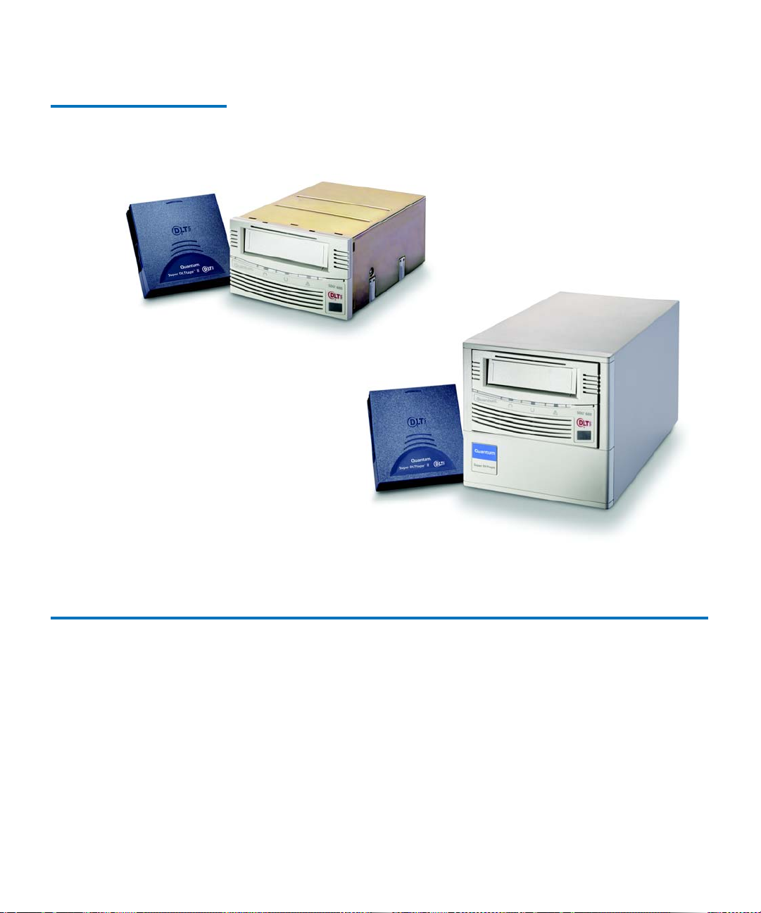
Figure 1 SDLT 600 Tape Drive
Systems
Internal model
Chapter 1 Tape Drive Product Information
Product Features
Tabletop model
Product Features 1
The SDLT 600 tape drive system offers the following product features:
• A streaming tape drive that uses half-inch wide Super Digital Linear
Tape (Super DLTtape II) media.
• A standard 5.25-inch full-height form factor to simplify integration
into system and tape library solutions.
SDLT 600 Product Manual 3
Page 20

Chapter 1 Tape Drive Product Information
Tape Drive Technology
• Backward read compatibility for SDLT 220 and SDLT 320 tape drive
formats with the Super DLTtape I data cartridge type; and the
DLT VS160 tape drive format with DLTtape
type.
• DLTSage iTalk (and Pocket DLTSage iTalk)—Infrared (wireless)
interface that provides a remote testing base allowing customers and
integrators to access system diagnostic information from the front of
the SDLT 600 tape drive system.
• The SDLT 600 tape drive is available in either Ultra 160 or Fibre
Channel interface versions.
• For more information on the SDLT 600 tape drive features and other
product information, you can access the Web site at:
http://www.dlttape.com/Home.htm
This web page provides information that is constantly updated as
needed. Refer to this Web site often to obtain the most current
information.
®
VS1 data cartridge
Tape Drive Technology 1
The SDLT 600 tape drive incorporates various new state-of-the-art
technologies that contribute to the SDLT architecture. Some of these ideas
are trademarked, others are patented. The following subsections
introduce the important technologies that together, comprise the SDLT
600 tape drive system.
Laser Guided Magnetic Recording
SDLT 600 Product Manual 4
The SDLT 600 tape drive systems (shown in figure 1) are based on
1
Quantum’s Laser Guided Magnetic Recording (LGMR) technology.
LGMR provides a unique combination of the best optical and magnetic
technologies, which results in dramatically higher capacities by
substantially increasing the number of recording tracks on the databearing surface of the media. By recording data magnetically on the databearing side of the media and using servo movement optically on the
backside, LGMR optimizes highly proven technologies to deliver the
most efficient, reliable, and scalable data backup solution to the midrange market.
Page 21

Chapter 1 Tape Drive Product Information
Tape Drive Technology
Pivoting Optical Servo 1 Pivoting Optical Servo (POS) is a Quantum-invented, optically-encoded
servo system, that combines high-density magnetic read/write data
recording with laser servo guiding. The POS provides high-duty-cycle
applications, which decreases cost and increases user convenience. The
POS enables the head to track dynamic variations in tape motion which
allows Quantum to provide a track count with an order of magnitude
increase over previous products.
Magneto Resistive Cluster Heads
Advanced Partial Response Maximum Likelihood
Advanced Metal Powder Media
Magneto Resistive Cluster (MRC) heads are a densely packed array of
1
small, cost-effective Magneto Resistive (MR) tape heads precisely
positioned using advanced thin-film processing technology. SDLT MRC
heads provide high wafer usage efficiency resulting in low head costs, are
less susceptible to variations in tape speed, yield higher track density and
capacity, and provide a multi-channel architecture for increased transfer
rate and performance.
Improving on Partial Response Maximum Likelihood (PRML) technology
traditionally used in disk drives and communication systems, Quantum’s
1
advanced PRML channel technology, co-developed with Lucent
Technologies, brings new levels of performance and capacity to highperformance linear tape products. This provides high-encoding efficiency
recording densities for greater capacity and performance that enables
SDLT to increase transfer rates and capacity substantially.
Advanced Metal Powder (AMP) media is a state-of-the-art media using
1
durable metal powder technology for recording very high densities of
data. The back side of the AMP media receives a specially formulated
coating to accept the optical servo tracks. Because the servo information is
on the back side of the media, the entire data-bearing side of the media is
available for recording data and eliminates the need for pre-formatting.
In addition, AMP media meets the needs of multiple generations of the
SDLT technology.
Positive Engagement T ape Leader Buckling Mechanism
SDLT 600 Product Manual 5
The positive engagement tape leader buckling mechanism is a highly
robust mechanism that increases data cartridge life and supports the
1
Page 22

Chapter 1 Tape Drive Product Information
Modular Design
extensive duty-cycle environments found in high-end and automation
environments.
This mechanism engages the tape leader upon data cartridge load and
disengages it upon data cartridge unload. It uses a solid metal pin
attached to the drive leader to link with molded clips permanently
attached to the tape leader inside the data cartridge. The Positive Leader
Link design makes the buckling of Super DLTtape media a totally reliable
mechanical process.
Modular Design 1
The SDLT 600 tape drive is designed as a total system. The system
includes a complex interaction of a number of important components
including such items as the tape path, tape heads, media, data cartridge,
and host interface.
As shown in figure 2
modules:
• Data Control Module (DCM)
• Tape Control Module (TCM)
• Front Panel Module (FPM)
• Electronic Interface Module (EIM)
• Super DLTtape II Data Cartridge (Data Cartridge).
The modular concept makes the SDLT 600 tape drive system easy to
manufacture and configure. Each module is optimized to perform a
specific set of functions and designed to interface with the other modules
in a well defined and flexible manner.
The following subsections provide a brief overview of each module.
, the SDLT 600 tape drive consists of five distinct
SDLT 600 Product Manual 6
Page 23
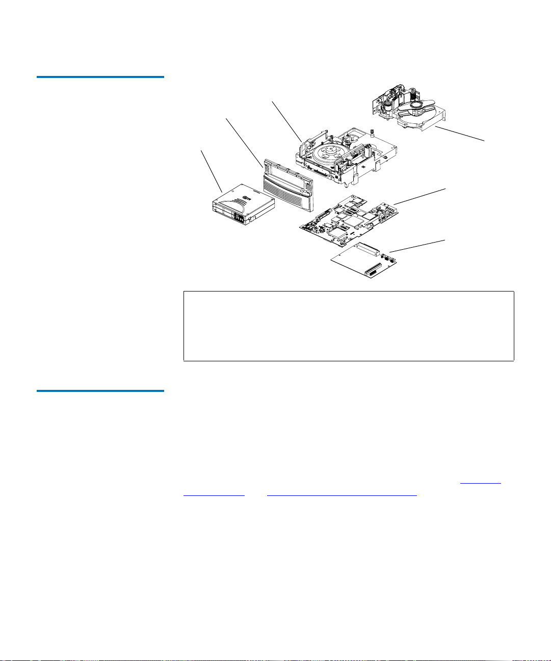
Figure 2 SDLT 600 Tape Drive
Modular Design
Chapter 1 Tape Drive Product Information
Modular Design
TCM
FPM
Data
Cartridge
EIM ICM
EIM HIM
DCM
Note: Despite the deliberate modularity of each module, with the
exception of the FPM, individual users should not swap
modules. The FPM is the only module that is field replaceable.
Customer adjustments to the TCM, DCM, or EIM will void the
tape drive’s warranty.
Data Control Module 1 The Data Control Module (DCM) contains several of the functions and
features of LGMR technology, which is at the heart of the SDLT
technology. Of the five technologies that constitute the LGMR
technology, two are in the DCM. These are the POS and the MRC heads.
The main functions of the DCM are to provide the path and guides for all
tape motion inside the tape drive and to write data to and read data from
the tape. In addition to the POS and MRC heads described in Pivoting
Optical Servo and Magneto Resistive Cluster Heads, the DCM contains a
number of components that interact to perform these functions. These
components include:
• Advanced head guide assembly
• Take-up reel
•Drive motor
• Optical servo system
SDLT 600 Product Manual 7
Page 24

Chapter 1 Tape Drive Product Information
Modular Design
• Tape heads.
In addition to its mechanical components, the DCM also contains printed
circuit boards that control the functions of the DCM and the tape heads.
Tape Control Module 1 The Tape Control Module (TCM) implements the functions required to
buckle and unbuckle the tape and control the tape motion. The TCM
consists of a variety of components:
• TCM Printed Circuit Board Assembly (PCBA)
• Base Plate
• Data Cartridge Receiver
• Positive Engagement Tape Leader Buckling Mechanism
• Tape supply motor assembly
• Floor plate assembly.
TCM PCBA
The TCM has its own PCBA that controls the functions of the TCM and
interfaces with the main controller board in the EIM. By designing the
TCM as a distinct module, it allows manufacturing and testing the TCM
as a stand-alone module, simplifying the design, manufacturing, and
troubleshooting processes.
Base Plate
The SDLT 600 tape drive base plate is an aluminum die casting with
precisely machined surfaces. The casting acts as the support platform for
the other modules and for the tape drive enclosure. The base plate also
includes the precision mounting holes used to install SDLT 600 tape
drives into a server or tape library. The SDLT 600 tape drive base plate,
and therefore the entire SDLT 600 tape drive, conforms to the 5.25 inch,
full-height form factor.
1
1
SDLT 600 Product Manual 8
Page 25

Chapter 1 Tape Drive Product Information
Modular Design
Data Cartridge Receiver 1
On tape insertion, the data cartridge receiver assembly guides the tape
into its operating position, opens the data cartridge door, unlocks the
data cartridge brakes, engages the data cartridge drive motor, and
secures the tape for operation. On tape ejection, the data cartridge
receiver assembly reverses the process and automatically ejects the tape a
fixed distance from the front of the tape drive.
Positive Engagement Tape Leader Buckling Mechanism
The buckling mechanism is responsible for engaging the tape leader upon
data cartridge load and disengaging it on data cartridge unload. See
Positive Engagement Tape Leader Buckling Mechanism
for more
information.
Front Panel Module 1 The Front Panel Module (FPM) of the system (sometimes referred to as
the bezel) performs a number of functions:
• Protecting the front of the TCM from physical damage
• Channeling airflow through the system
• Aligning the data cartridge when it is inserted into the system
• Providing system status and information through LEDs
• Enabling data cartridge ejection
• Delivering the overall cosmetic look of the system.
The FPM is a single module with lenses for the system’s LEDs and a
button to activate the drive eject switch. The SDLT 600 tape drive front
panel contains no electronics.
1
Electronic Interface Module
1
The Electronic Interface Module (EIM) is the electronic heart of the SDLT
600 tape drive system. It provides the main control function for the
system and the interface from the system to the host computer, library, or
autoloader. The EIM provides the Advanced PRML feature of Quantum’s
SDLT technology. See Advanced Partial Response Maximum Likelihood
on page 5 for a brief description of PRML.
SDLT 600 Product Manual 9
Page 26

Chapter 1 Tape Drive Product Information
Quantum Diagnostics Tools
The EIM consists of two major boards: the Integrated Controller Module
(ICM), and a separate Host Interface Module (HIM). The ICM contains
the main controller and servo microprocessor, the custom-designed SDLT
ASICs, and the cache memory while the HIM implements the interface
between the host system and the tape drive. This allows easy
configuration of the tape drive to match different host interfaces by
simply substituting the appropriate HIM card.
As with the other major modules of the SDLT technology, the EIM is
manufactured and tested as a distinct module.
Super DLTtape II Data Cartridge
As with all tape technologies, the Super DLTtape II data cartridge is a key
1
part of the overall system. The main function of the data cartridge is to
provide the magnetic recording media used by the system to store
customer information. The data cartridge also provides the protective
casing that allows safe media movement and storage.
From the outside, the Super DLTtape II data cartridge looks very similar
to the Super DLTtape I and DLTtape VS1 data cartridges. The basic
geometry, write protection switch, and label space are the same. This
simplifies the integration of the SDLT 600 tape drive into existing
operating environments and into automated tape libraries. The
Super DLTtape II data cartridge is easy to recognize; it has a different
color than the Super DLTtape I and DLTtape VS1 data cartridges, and
contains a distinctive pattern molded into the shell. The DLTtape logo
and the product name are also molded into the shell, which ensure you
have a genuine Quantum Super DLTtape II data cartridge.
Quantum Diagnostics Tools 1
Quantum frequently provides new and updated tools to use with its tape
drives. These tools include such items as upgrades for product software
and firmware, and diagnostic software that may be newly developed. All
these tools are available on the Quantum Web site.
Note: These tools are only available to registered Quantum
customers.
SDLT 600 Product Manual 10
Page 27

Chapter 1 Tape Drive Product Information
Refer to the following procedure to access these tools.
TapeAlert
1 Go to the Quantum Web site: http://www.quantum.com
2 Click
3 Explore the various pages that comprise Service and Support until
New tools and utilities get added frequently, so check back often.
SERVICE AND SUPPORT in the upper menu bar. This opens the
Service and Support window.
you find what you need.
.
TapeAlert 1
SDLT 600 tape drives are delivered with TapeAlert™ features built in.
The internal SDLT firmware constantly monitors the device’s hardware
and media, checking for errors and potential difficulties. It flags any
problems identified on the SCSI log page, where 64 bytes are reserved for
use by TapeAlert.
After a backup, the TapeAlert-compatible backup application
automatically reads the device’s TapeAlert SCSI log page to check for any
problems. If an error is flagged, your backup software displays a clear
warning message on your screen, and adds the TapeAlert messages to its
logs. These messages are standard across all applications that support
TapeAlert, and give clear explanation of the problem and suggested
resolution. For example, if you were attempting to back up onto an
expired tape, you would see the following message:
Warning: The data cartridge has reached the end of its useful life:
Copy any data you need to another tape. Discard the old
tape.
Medium Auxiliary Memory
Medium Auxiliary Memory (MAM) is a feature in the SDLT 600 tape
drive that produces various attributes about the data cartridge and
records them in a log file on the media itself. These attributes provide the
underlying information for the DLTSage suite of predictive and
preventive maintenance diagnostics software.
SDLT 600 Product Manual 11
1
Page 28

Chapter 1 Tape Drive Product Information
TapeAlert
For more information about MAM, see the SDLT 600 SCSI Interface Guide
(81-81200-xx)
For more information about DLTSage, see the
Guide (81-81201-xx)
or the SDLT 600 Fibre Channel Interface Guide (81-81202-xx).
DL TSage Implementation
.
SDLT 600 Product Manual 12
Page 29

Chapter 2
2SDLT 600 Tape Drive
Specifications
This chapter describes various specifications that apply to the Quantum
SDLT 600 tape drive system:
• Product Specifications
• Functional Specifications
tape drive
• Environmental Specifications
for operating the tape drive
• Recording Media Specifications
Super DLTtape II data cartridges.
provides tape drive specifications
provides functional specifications for the
provides environmental specifications
provides media specifications for
Product Specifications 2
The following subsections contain full product specifications for the
Quantum SDLT 600 tape drive.
Host Interface 2 The Ultra 160 SCSI and Fibre Channel interfaces are available in both the
internal and tabletop models.
SDLT 600 Product Manual 13
Page 30

Chapter 2 SDLT 600 Tape Drive Specifications
Table 1 SDLT 600 Tape Drive
Interface Versions Sp eeds and
Options
Interface Versions Speeds Protocol Options
Product Specifications
Fibre Channel
• 100 MB/second
• 200 MB/second
• Class3
• Connect to N port, NL port, FL port
• FC-MI
• FC-AL-2
• FCP-2
• FC-FS
• SCSI-3 (SAM-2, SPC-2, or SSC)
Ultra 160
• 160 MB/second
maximum burst speed
• Multi-mode Single-Ended (MSE)
**
provides one of two differential senses:
- Low Voltage Differential (LVD) running
up to 160 MB/second, or
- Single Ended (SE) running up to 40
MB/second
• Ultra 160 2/FAST-20/Asynchronous
• SCSI-3 (SAM-2, SPC-2, and SSC)
• Supports up to 15 hosts
** The SCSI bus itself limits this speed, not the design of SDLT 600 tape drive or Super DLTtape II
media.
Ultra 160 SCSI Interface 2
The Ultra 160 SCSI interface provides a low-voltage differential (LVD)
mode running up to
160 MB/second and a single-ended (SE) mode running up to 40 MB/
second.
Note: The host computer’s SCSI controller card may limit these
speeds. To achieve the best performance, make sure the SCSI
controller card can operate at 160 MB/second.
SDLT 600 Product Manual 14
Page 31

Chapter 2 SDLT 600 Tape Drive Specifications
Product Specifications
The tape drive automatically senses the SCSI bus mode and switches
between LVD and SE accordingly. Although the tape drive defaults to
LVD, it switches to SE if the SCSI bus operates in SE mode. For example,
if the SCSI controller card is SE (or multimode set to SE), the tape drive
automatically switches to SE mode. Also, if any device on the SCSI bus is
SE, the entire bus switches to SE, including the tape drive.
In SE mode, the SCSI bus can support up to 7 devices using cable lengths
up to 3 meters. In LVD mode, the SCSI bus can support up to 15 devices
using cable lengths up to 25 meters.
For more information about the SCSI interface, see the
Interface Guide (81-81200-xx)
.
SDLT 600 SCSI
Fibre Channel Interface
The Fibre Channel interface runs at speeds up to either 1 Gb/second or 2
Gb/second, depending on the configuration you choose during
installation.
Fibre Channel can support up to 126 devices in a loop configuration.
Longwave transceivers (with fiber optic cable) support distances up to 10
kilometers; shortwave transceivers (with fiber optic cable) support
distances up to 500 meters.
For more information about the Fibre Channel interface, see the
Fibre Channel Interface Guide (81-81202-xx)
.
SDLT 600
2
SDLT 600 Product Manual 15
Page 32

Chapter 2 SDLT 600 Tape Drive Specifications
Product Specifications
Physical Interface 2 The SDLT 600 tape drive has the interfaces shown in table 2 available
from the back panel (per type, per port).
Table 2 SDLT 600 Tape Drive
Interface
Physical Dimensions and Weights
Table 3 SDLT 600 Tape Drive
Physical Dimensions
Interface
Versions Physical Characteristics
Fibre
Topology-constrained (force point-to-point)
Channel
1 Gbit or 2 Gbit interface (selectable at time of
installation)
850 nanometer LC connector transceiver (optional)
Parallel SCSI MSE, LVD
Ultra 160
SCSI ID (user selectable at time of installation)
TERMPWR connector style: 4-pin
Connector style: 68-pin high density SCSI
Table 3 provides physical dimensions for the SDLT 600 tape drive system.
2
Tabletop
Internal Version Library Version
Version
Height 82.55 mm (3.25 in.)
without front bezel
85.73 mm (3.38 in.)
with front bezel
Width 146.05 mm (5.75 in.)
behind front bezel
148.59 mm (5.85 in.)
with front bezel
SDLT 600 Product Manual 16
82.55 mm (3.25 in.)
without front bezel
85.73 mm (3.38 in.)
with front bezel
146.05 mm (5.75 in.)
behind front bezel
148.59 mm (5.85 in.)
with front bezel
164.46 mm
(6.48 in.)
174.75 mm
(6.88 in.)
Page 33

Chapter 2 SDLT 600 Tape Drive Specifications
Internal Version Library Version
Product Specifications
Tabletop
Version
Table 4 SDLT 600 Tape Drive
Shipping Weight
Depth 203.20 mm (8.00 in.)
from back of front
bezel
215.40 mm (8.48 in.)
including front
203.20 mm (8.00 in.)
from back of front
bezel
212.22 mm (8.36 in.)
including front bezel
320.04 mm
(12.60 in.)
bezel
Mounting hole pattern for the bottom and sides of the system is
industry standard.
Table 4 shows the weights of the SDLT 600 tape drive.
Internal Version Tabletop Version
Weight* 2.38 kg (5 lbs. 4 oz) 6.27 kg (13 lbs. 13 oz)
Shipping Weight* 3.77 kg (8 lbs. 5 oz) 9.90 kg (21 lbs. 13 oz)
* Weights depend on configuration. The packaging used may
change the shipping weight.
Compression 2 The tape drive contains on-board hardware to compress and decompress
data using a DLZ algorithm. The default setting for data compression is
on.
SDLT 600 Product Manual 17
Page 34

Chapter 2 SDLT 600 Tape Drive Specifications
Product Specifications
Storage Capacity 2 Table 5 provides native and compressed capacity ranges for the Super
DLTtape II data cartridge:
Table 5 SDLT 600 Tape Drive
Storage Capacity
Mode Capacity
Native Storage Capacity 300 GB
Compressed Storage Capacity 600 GB (2:1 compression ratio)
In accordance with industry practice, a typical compression ratio of 2:1 is
quoted. The redundancy and type of data files being written determine
the actual compression ratios achieved.
Data Integrity 2 SDLT 600 tape drive data transfer errors are extremely rare; table 5 shows
data integrity for the overall SDLT 600 tape drive system.
Table 6 Date Transfer Error
Rates
Error Type Frequency
Detected, Recoverable (ECC)
< 1 error in 10
6
bytes read
READ
17
Detected, Unrecoverable READ < 1 error in 10
Undetected READ < 1 error in 10
Rewrite of Data < 1 per 10
bits read
27
bits read
6
bytes written
SDLT 600 Product Manual 18
Page 35

Chapter 2 SDLT 600 Tape Drive Specifications
Product Specifications
Maximum Data Transfer Rate
Table 7 Maximum Data
Transfer Rates
Table 7 shows the maximum sustained (and burst) data transfer rates for
2
the SDLT 600 tape drive.
Configuration Native Compressed* Burst Max**
SCSI Ultra 160
36 MB/sec 72 MB/sec 160 MB/sec
(MSE LVD
mode)
SCSI Ultra 160
36 MB/sec 40 MB/sec 40 MB/sec
(SE mode)
Fibre Channel
36 MB/sec 72 MB/sec 100 MB/sec
(1 Gbps)
Fibre Channel
36 MB/sec 72 MB/sec 200 MB/sec
(2 Gbps)
* The compression rates shown assume an industry standard 2:1
compression ratio. Actual compression ratios achieved depend on
the redundancy of data files being recorded. For non-compressible
(expanding) data, this results in a reduction in capacity and
transfer rate for the data. Fully random data is the worst case for
compressibility.
** The SCSI bus limits burst speeds, not the design of SDLT 600 tape
drive or Super DLTtape II media.
Note: Cable lengths and cable type may limit attainable transfer rate;
for details, see the
(81-81196-xx).
SDLT 600 Product Manual 19
SDLT 600 Design and Integration Guide
Page 36

Chapter 2 SDLT 600 Tape Drive Specifications
Product Specifications
Head Life and MTBF 2 The projected mean time between failures (MTBF) for the overall SDLT
600 tape drive system is 250,000 hours, not including the heads. Head life
is a minimum of 30,000 tape motion hours and an average of 50,000
media motion hours.
Note: The manufacturer does not warrant that predicted MTBF is
representative of any particular unit installed for customer
use. Actual figures vary from unit to unit.
Media Durability 2 Table 8 shows the number of media passes and full media uses to expect
from a Super DLTtape II data cartridge.
Table 8 SDLTtape II Data
Cartridge Media Durability
Data Cartridge Life Expectancy
Media Durability
Media passes* 1,000,000
Full media uses
** 250
* A media pass occurs with any movement (in either direction) of
the surface of the media over the tape head.
** A full media use is an operation that reads or writes (with verify
off) the full capacity of the data cartridge.
Table 9 shows the number of load and unload cycles you can expect
2
before the data cartridges need to be replaced.
SDLT 600 Product Manual 20
Page 37

Chapter 2 SDLT 600 Tape Drive Specifications
Functional Specifications
T able 9 Loading and Unloading
the Data Cartridge (Maximum)
Positive Engagement T ape Leader Buckling Mechanism
Super DLTtape II Data Cartridge
Data cartridge load/unload
cycles*
Media insertions
* A load/unload cycle is when a data cartridge is inserted into the
receiver, loaded to BOT, calibrated, and then unloaded.
** An insertion is when a data cartridge is inserted into the receiver
and then unloaded.
This buckling mechanism engages the tape leaders upon data cartridge
load and disengages them upon data cartridge unload.
2
Component level tests of buckle arm components have shown at least
250,000 cycles on an SDLT 600 tape drive without failure, breakage, or
binding; this includes the take-up leader, the supply leader, and the
media itself.
** 20,000
5,000
Functional Specifications 2
The following subsections contain functional specifications for the
Quantum SDLT 600 tape drive.
Performance Data 2 Table 10 provides performance data for the SDLT 600 tape drive system.
For a comparison of SDLT 600 tape drive storage capacities, see Storage
Capacity on page 18.
SDLT 600 Product Manual 21
Page 38

Chapter 2 SDLT 600 Tape Drive Specifications
Functional Specifications
Table 10 SDLT 600 Tape Drive
Performance Data
Feature SDLT 600 Tape Drive
Drive Read/Write Transfer Rate* 36 MB/second, native
72 MB/second, compressed
Tracks 40 logical tracks
640 physical tracks
Track Density 1502 tracks per inch (tpi)
Linear Bit Density 233 Kbits per inch (Kbpi)
Read/Write Tape Speed 108 inches per second (ips)
Rewind Tape Speed 160 ips
Linear Search Tape Speed 160 ips
Average Rewind Time** 77 seconds
Maximum Rewind Time** 156 seconds
Average Access Time** (from
79 seconds
BOT)
Maximum Access Time** (from
190 seconds
BOT)
Load to BOT** 18 seconds (typical)
63 seconds (unformatted tape)
Unload from BOT** 19 seconds
Nominal Tape Tension Stationary: 3.0 ± 0.5 oz
Operating Speed: 3.5 ± 0.5 oz
* Depending on data type and SCSI bus limitations/system
configuration.
** Note that data is typical; times may be longer if error recovery
time is necessary, or if the command times out for any reason. For
information on SCSI command timeout values, see the
Design and Integration Guide, 81-81196-xx.
SDLT 600 Product Manual 22
SDLT 600
Page 39

Chapter 2 SDLT 600 Tape Drive Specifications
Functional Specifications
Shock and Vibration Specifications
Table 11 Non-operating Shock
Specifications (Unpackaged)
Table 12 Non-Operating
Shock Specifications
(Packaged, Drop)
The following tables provide non-operating and operating shock and
2
vibration specifications for the SDLT 600 tape drive system.
Shock (Unpackaged)
Pulse Shape Square wave ½ sine pulse
Peak Acceleration 40 G 140 G
Duration 10 ms (180 inches/
2 ms
second)
Application X,Y,Z axes, twice in each axis (once in each
direction)
Shock
(Packaged,
Drop)
Drop 42 inches 16 drops
Height
of Drop
Number
of Drops Package Weight
0 lbs. < package weight
total
20 lbs.
≤
Table 13 Non-Operating
Vibration Specifications
(Unpackaged)
36 inches 16 drops
total
Vibration (Unpackaged)
20 lbs. < package weight
50 lbs.
≤
Type Sine Sweep
Frequency Range 5 to 500 to 5 Hz Upward and
downward sweep
Acceleration Level 0.02" DA
1.0 G
Between 5 and 31 Hz
(crossover)
Between 31 and 500
Hz (crossover)
SDLT 600 Product Manual 23
Page 40

Chapter 2 SDLT 600 Tape Drive Specifications
Functional Specifications
Vibration (Unpackaged)
Application X,Y,Z axes Sweep rate = ½
octave/minute
Type Random
Frequency Range 10 to 500 Hz
Acceleration Level 2.0 G
2
PSD Envelope 0.008 G
/Hz
Application X,Y,Z axes Sweep rate = 60
minutes/axis
Table 14 Non-Operating
Vibration Specifications
(Packaged)
Vibration (Packaged)
Type Random
Frequency Range Truck Profile* (0.5 Grms)
Air Profile* (1.0 Grms)
Application X,Y,Z axes (30 minutes, each profile and each
axis, for a total of 3 hours)
Type Sine, Sweep, and Dwell
Frequency Range 5 to 150 to 5 Hz; 0.5 octave/minute, 0.5 G
Application X,Y,Z axes; dwell at lowest resonant
frequency in axis for 30 minutes.
Additional 30 minutes for each additional
resonance; up to 4 resonances total.
* Air and truck profiles are specified in ASTM D4728, Standard Test
Method for Random Vibration Testing of Shipping Containers.
SDLT 600 Product Manual 24
Page 41

Chapter 2 SDLT 600 Tape Drive Specifications
Functional Specifications
Table 15 Operating Shock and
Vibration Specifications
Shock
Pulse Shape ½ sine pulse
Peak Acceleration 10 G
Duration 10 ms
Application X,Y,Z axes, twice in each axis (once in each
direction)
Vibration
Type Sine Sweep
Frequency Range 5 to 500 to 5 Hz Upward and downward
sweep
Acceleration Level 0.25 G
0.010" DA
Between 22 and 500 Hz
Between 5 and 22 Hz
(crossover)
Application X,Y,Z axes Sweep rate = 1.0 octave/
minute
Current and Power Requirements
Table 16 lists the current and power requirements for the two versions of
2
the SDLT 600 tape drive system (internal and tabletop) configured with
the SCSI interface. Table 17
lists the current and power requirements for
the internal version of the SDLT 600 tape drive system configured with
the Fibre Channel interface. The library version of the SDLT 600 tape
drive uses the same amount of power as the internal version with both
the SCSI and Fibre Channel interfaces. The tabletop version requires AC
power.
The tape drive draws the highest current (and power) during the native
write modes.
untensioned, and
SDLT 600 Product Manual 25
Standby is measured with the tape loaded and tensioned or
Idle is measured with power on with no tape loaded.
Page 42

Table 16 Current and Power
Requirements (SCSI Interface)
Chapter 2 SDLT 600 Tape Drive Specifications
Functional Specifications
(The power drawn in these two modes is similar enough that they are
listed together.)
Note: In table 16 and table 17, the current and DC power values
pertain to the internal tape drive, while the AC power values
apply to the tabletop tape drive.
Mode
5 V Current (A)
MaxPk
MaxMean
Typ
1
2
3
12 V Current (A)
MaxPk
MaxMean
Typ
1
2
3
DC Power
(W)
4
Max
5
Typ
AC Power
(W)
6
Max
7
Typ
Standby/Idle 2.6 2.6 2.4 0.2 0.1 0.1 14 14 47 45
Media Loading/
6.2 5.3 3.4 2.7 0.9 0.7 30 26 64 56
Unloading
600 Write– Motor
8
Start
600 Write–
4.3 4.0 3.7 1.3 0.3 0.3 23 22 51 48
5.4 5.1 4.9 0.7 0.5 0.4 30 30 65 63
Streaming
SDLT 600 Product Manual 26
Page 43

Chapter 2 SDLT 600 Tape Drive Specifications
Functional Specifications
Mode
Max for
SDLT 600 tape
drive Modes
9
5 V Current (A)
MaxPk
MaxMean
Typ
1
2
3
12 V Current (A)
MaxPk
MaxMean
Typ
1
2
3
n/a 5.3 n/a n/a 0.9 n/a 30 n/a 70 n/a
DC Power
(W)
4
Max
5
Typ
AC Power
(W)
6
Max
7
Typ
1. The Max-Peak value represents short current spikes drawn for durations of < 50ms. On the 12V
supply, the peaks correspond to the pulse-width-modulated switching of the motors. These values
are calculated from the average of Peak-ripple-current + 2 sigma, measured at nominal DC voltage.
2. The Max-Mean value is the average of the maximum RMS current drawn during this operating
mode. These values are calculated from the average of RMS current + 3 sigma, measured at nominal
DC voltage.
3. The typical current is calculated from the average of all RMS current drawn during this operating
mode, measured at nominal DC voltage.
4. The Max DC power is calculated from the typical DC power + 3 sigma, measured at nominal DC
voltage. This value takes into account that the peak currents on the 5V and 12V do not occur at the
same time.
5. The Typical DC power is calculated from the average RMS DC power drawn during this operating
mode, measured at nominal DC voltage. This value also takes into account that the peak currents
on the 5V and 12V do not occur at the same time.
6. The Max AC power is calculated from the typical AC power in tabletop tape drives + 3 sigma.
7. The Typical AC power is calculated from the average of AC power drawn in tabletop tape drives.
8. These events last < 1 second and occur at a duty cycle of less than 25%.
9. The Max values for each mode are based on the Max-Mean values, since the peak values are of very
short duration.
(Common Notes)
(1) Voltage tolerance: 5V ±5%, 12V ±5%; Room temperature 24 °C. AC power measured at 117 V,
60 Hz.
(2) DC Current, MaxMean, and DC/AC Power Max refer to the statistically calculated maximum
average requirement based on a sample population of tape drives. These values do not reflect the
peak current or power requirement; this amount is given by the DC MaxPk current.
SDLT 600 Product Manual 27
Page 44

T able 17 Current and Power
Requirements (Fibre
Channel Interface)
Chapter 2 SDLT 600 Tape Drive Specifications
Functional Specifications
Mode
5 V Current (A)
MaxPk
MaxMean
Typ
1
2
3
12 V Current (A)
MaxPk
MaxMean
Typ
1
2
3
DC Power
(W)
4
Max
5
Typ
AC Power
(W)
6
Max
7
Typ
Standby/Idle 3.5 3.5 3.1 0.2 0.1 0.1 18 17 n/a n/a
Media Loading/
5.4 4.4 4.4 2.7 0.7 0.7 30 30 n/a n/a
Unloading
600 Write– Motor
8
Start
600 Write–
4.6 4.3 4.2 1.3 0.3 0.3 25 25 n/a n/a
5.9 5.6 5.5 0.7 0.5 0.4 33 33 n/a n/a
Streaming
SDLT 600 Product Manual 28
Page 45

Chapter 2 SDLT 600 Tape Drive Specifications
Functional Specifications
Mode
Max for
SDLT 600 tape
drive Modes
9
5 V Current (A)
MaxPk
MaxMean
Typ
1
2
3
12 V Current (A)
MaxPk
MaxMean
Typ
1
2
3
n/a 5.6 n/a n/a 0.7 n/a 33 n/a n/a n/a
DC Power
(W)
4
Max
5
Typ
AC Power
(W)
6
Max
7
Typ
1. The Max-Peak value represents short current spikes drawn for durations of < 50ms. On the 12V
supply, the peaks correspond to the pulse-width-modulated switching of the motors. These values
are calculated from the average of Peak-ripple-current + 2 sigma, measured at nominal DC voltage.
2. The Max-Mean value is the average of the maximum RMS current drawn during this operating
mode. These values are calculated from the average of RMS current + 3 sigma, measured at nominal
DC voltage.
3. The typical current is calculated from the average of all RMS current drawn during this operating
mode, measured at nominal DC voltage.
4. The Max DC power is calculated from the typical DC power + 3 sigma, measured at nominal DC
voltage. This value takes into account that the peak currents on the 5V and 12V do not occur at the
same time.
5. The Typical DC power is calculated from the average RMS DC power drawn during this operating
mode, measured at nominal DC voltage. This value also takes into account that the peak currents
on the 5V and 12V do not occur at the same time.
6. The Max AC power is calculated from the typical AC power in tabletop tape drives + 3 sigma.
7. The Typical AC power is calculated from the average of AC power drawn in tabletop tape drives.
8. These events last < 1 second and occur at a duty cycle of less than 25%.
9. The Max values for each mode are based on the Max-Mean values, since the peak values are of very
short duration.
(Common Notes)
(1) Voltage tolerance: 5V ±5%, 12V ±5%; Room temperature 24 °C. AC power measured at 117 V,
60 Hz.
(2) DC Current, MaxMean, and DC/AC Power Max refer to the statistically calculated maximum
average requirement based on a sample population of tape drives. These values do not reflect the
peak current or power requirement; this amount is given by the DC MaxPk current.
SDLT 600 Product Manual 29
Page 46

Chapter 2 SDLT 600 Tape Drive Specifications
Environmental Specifications
SDLT 600 Tape Drive System Recording Method
2
The SDLT 600 tape drive system uses the Partial Response Maximum
Likelihood (PRML) 32/33 encoding method for reading/writing SDLT
600 tape drive format. It uses the same algorithmm for reading SDLT 220,
SDLT 320, and the DLT VS160 tape drive formats.
Environmental Specifications 2
The SDLT 600 tape drive system operates in environments that include
general offices and work spaces with systems capable of maintaining
standard comfort levels.
The following subsections provide the environmental specifications for
the SDLT 600 tape drive systems (both the internal and the tabletop
configurations). For long-term trouble-free operation, the manufacturer
strongly recommends that SDLT 600 tape drives be used in a clean,
smoke-free environment.
Air Flow Requirements 2 The internal tape drive requires adequate air flow to dissipate the heat
resulting from continuous drive operation. Specifically, the air flow must
be sufficient to keep the tape path temperature below 50 °C.
To allow enough air into the tape drive to keep the tape path below this
temperature, it is important to keep the cooling holes in the rear and the
grill in the front of the tape drive clear of any obstructions that may
hinder the air flow. For more details about airflow, see the S
Design and Integration Guide (81-81196-xx)
Note: It is also important to limit the ambient air temperature to no
greater than 40 °C.
SDLT 600 Product Manual 30
.
DLT 600
Page 47

Chapter 2 SDLT 600 Tape Drive Specifications
Environmental Specifications
Temperature and Humidity 2 The ambient operating environment for the tape drive may not exceed
the limits shown in table 18
. (The specifications shown in the table are
valid for both the internal and tabletop tape drives.)
Table 18 Temperature and
Humidity Specification
Specification
Wet Bulb
Operating Limits
25 °C (77 °F) 25 °C (77 °F)
Non-Operating
Limits (Power On,
No Tape Loaded)
Temperature
Dry Bulb
Temperature Range
Temperature
Gradient
Relative Humidity 20% to 80% (non-
10 °C to 40 °C (50 °F
to 104 °F)
11 °C (20 °F)/hour
(across range)
condensing)
10 °C to 40 °C (50 °F
to 104 °F)
15 °C (27 °F)/hour
(across range)
10% to 90% (noncondensing)
Humidity Gradient 10%/hour 10%/hour
Storage and Shipment 2 The ambient storage and shipment environment for the tape drive may
not exceed the limits shown in table 19
. (The specifications shown in the
table are valid for both the internal and tabletop tape drives.)
Table 19 Tape Drive Storage
and Shipment Specifications
Specification*
Wet Bulb
Storage
(Unpacked or
Packed)
Shipping
46 °C (114 °F) 46 °C (114 °F)
Temperature
Dry Bulb
Temperature
Temperature
Gradient
SDLT 600 Product Manual 31
–40 °C to 66 °C (–40
°F to 150 °F)
20 °C (36 °F)/hour
(across range)
–40 °C to 66 °C (–40
°F to 150 °F)
20 °C (36 °F)/hour
(across range)
Page 48

Chapter 2 SDLT 600 Tape Drive Specifications
Recording Media Specifications
Relative Humidity 10 to 95% (non-
condensing)
Humidity Gradient 10%/hour 10%/hour
Note: These specifications apply to the tape drive only. Media
specifications are listed in Recording Media Specifications
Altitude 2 Both the internal and tabletop tape drives operate in normal pressures
from –500 to 10,000 feet when operated within the ambient operating
environments specified in Temperature and Humidity
The SDLT 600 tape drive will operate to 30,000 feet for temperatures
within 15 ± 5 °C.
10 to 95% (noncondensing)
.
.
Recording Media Specifications 2
Super DLTtape II media differs slightly from previous generations of
Super DLTtape media. Table 20
DLTtape II media.
shows overall specifications for Super
Table 20 Super DLTtape II
Media Specifications
SDLT 600 Product Manual 32
Characteristic Specification
Overall tape thickness 8.0 µm
Media length, total 2066 feet
Media length, usable 1957 feet
Page 49

Chapter 2 SDLT 600 Tape Drive Specifications
Recording Media Specifications
Media Structure 2 Super DLTtape II media comprises several layers, as shown in figure 3.
Figure 3 Multiple Layers
Comprise Super DLTt ape II
Media
Layers not drawn to scale
High Coercivity
Magnetic Layer
Under Layer
Enhanced Base
Film Layer
Back Coat Layer
with Servo Guides
SDLT 600 Product Manual 33
Page 50

Chapter 2 SDLT 600 Tape Drive Specifications
Recording Media Specifications
Physical Data Cartridge 2 A durable plastic case encloses the Super DLTtape II media, as shown in
figure 4
Figure 4 Super DLTtape II
Data Cartridge
.
Media Shipping,
The optimum media shipping conditions are described in table 21.
Operating, and Storage
Specifications
Table 21 Super DLTtape II
Media Shipping Limits
2
Shipping Conditions
Temperature –18 °C to 49 °C (0 °F to 120 °F)
Relative Humidity 20 to 80% (non-condensing)
Maximum Wet Bulb
26 °C (79 °F)
Temperature
Maximum Dew Point 2 °C (36 °F)
SDLT 600 Product Manual 34
Page 51

Chapter 2 SDLT 600 Tape Drive Specifications
Recording Media Specifications
Table 22 Super DLTtape II
Media Operating Limits
Table 23 Super DLTtape II
Media Storage Limits
Operating Conditions
Temperature 10 ° to 40 °C (50 ° to 104 °F)
Relative Humidity 20% to 80% (non-condensing)
Table 23 describes the optimum media storage conditions.
Storage Conditions Archival Non Archival
Temperature 18 ° to 28 °C
(64 ° to 82 °F)
Relative Humidity 40% to 60%
(non-condensing)
16 ° to 32 °C
(60 ° to 90 °F)
20% to 80%
(non-condensing)
SDLT 600 Product Manual 35
Page 52

Chapter 2 SDLT 600 Tape Drive Specifications
Recording Media Specifications
Backward-Read Compatibility Transfer Rates
Table 24 SDLT 600 Tape
Drive Backward-Read
Compatibility (BRC) Transfer
Rates
The SDLT 600 tape drive system features a backward-read compatibility
(BRC) mode. When in BRC mode, the SDLT 600 tape drive is capable of
2
reading SDLT 220 and SDLT 320 tape formats in a Super DLTtape I data
cartridge, as well as the DLT VS160 tape format in the DLTtape VS1 data
cartridge.
Table 24
lists the BRC transfer rates for the SDLT 600 tape drive.
BRC Transfer
Rate (80% of
Native Read
Format
Data Cartridge
Type
Native
Capacity
Transfer
Rate)*
SDLT 320 Tape Drive Super DLTtape I 160 GB 12.8 MB/sec**
SDLT 220 Tape Drive Super DLTtape I 110 GB 8.8 MB/sec**
DLT VS160 Tape
DLTtape VS1 80 GB 6.4 MB/sec**
Drive
* The manufacturer strives to operate BRC transfer rate at 100% of
native read transfer rate, but guarantees 80%.
** Transfer rates shown are nominal based on 80% of actual native
read transfer rate of uncompressed data.
Note: SDLT 600 tape drive will eject a data cartridge written in DLT
formats other than DLT VS160.
SDLT 600 Product Manual 36
Page 53

Chapter 3
3Installing Your
Tape Drive
This chapter describes how to install the SDLT 600 tape drive. This
includes configuration jumper settings, connector pin assignments,
installation instructions, power and signal cabling descriptions, and
operating instructions. This chapter also includes information on
configuring and connecting the tabletop version of the tape drive into a
system.
This chapter covers the following topics:
• Warranty Note
follow so that you do not void your warranty.
• Safety, Handling, and ESD Protection
safeguards to use when working with the SDLT 600 tape drive
system.
• Pre-Installation Guidelines
installing the tape drive in a system. This includes recording the
model and serial numbers, and checking that the proper SCSI (or
Fibre Channel) controller and cable have been delivered.
• Configuring and Installing an Internal Tape Drive with SCSI
Interface describes how to configure and install an internal tape drive
with the SCSI interface into a system.
• Configuring and Installing an Internal Tape Drive with Fibre
Channel Interface describes how to configure and install an internal
tape drive with the Fibre Channel interface into a system.
SDLT 600 Product Manual 37
provides a general reminder of certain precautions to
describes appropriate
describes proper steps to take before
Page 54

Chapter 3 Installing Your Tape Drive
Warranty Note
• Configuring and Installing a Tabletop Tape Drive with SCSI Interface
describes how to configure and install the tabletop version of the tape
drive.
• Confirming the Installation
drive has been installed correctly.
describes how to confirm that the tape
W arranty Note 3
Please refer to the warranty before installing your tape drive. Certain
actions taken during installation could void the warranty if not properly
conducted.
Generally, the Limited Product and Limited Repair Warranties are
contingent upon proper use in the application for which the product is
intended; and do not cover the product if you perform any of the
following actions:
• Modify the product without the manufacturer’s written approval.
• Subject the product to unusual physical, environmental, or electrical
stress, including damage caused by handling or shipping in
unapproved containers or packaging.
• Disturb any warranty labels, or the integrity of the product in any
other way.
• Remove or damage the serial number label to the extent that
warranty status of the product cannot be determined.
Safety, Handling, and ESD Protection 3
Inappropriate or careless handling of SDLT 600 tape drive systems may
result in damage to the product. Follow the precautions and directions to
prevent damaging the SDLT 600 tape drive system. In addition, follow
the steps in Pre-Installation Guidelines
have the correct hardware for your system configuration.
SDLT 600 Product Manual 38
on page 41 to ensure that you
Page 55

Chapter 3 Installing Your Tape Drive
Safety, Handling, and ESD Protection
Safety Precautions 3 For your safety, follow all safety procedures described here and in other
sections of the manual.
1 Power off the system before installing or removing the tape drive to
prevent the possibility of electrical shock or damage to the tape drive.
Unplug the unit that contains—or is to contain—the tape drive from
AC power to provide an added measure of safety.
2 Read, understand, and observe all label warnings.
3 The POS uses a Class I laser product. This laser product complies
with 29 CFR 1200 and 29 CFR 1910 as applicable on the date of
manufacture.
Warning: If you open the tape drive chassis, you may become
exposed to invisible laser emission which could be
harmful if you are directly exposed to the beam.
Handling 3 Damage to the SDLT 600 tape drive system can occur as the result of
careless handling, vibration, shock, or electrostatic discharge (ESD). For
more details about ESD, see Electrostatic Discharge Protection
.
Caution: Always handle the SDLT 600 tape drive system with care
to avoid damage to the precision internal components.
Hold the internal tape drive by the sides, or the tabletop
tape drive by the bottom. Never hold either tape drive by
inserting fingers into the receiver area on the front of the
tape drive. Damage to the receiver area may occur if you
lift or carry it in this manner.
Follow these guidelines to avoid damage to the tape drive:
• Always observe prescribed ESD precautions.
• Keep the internal tape drive in its anti-static bag until ready to install.
• Always use a properly fitted wrist strap or other suitable ESD
protection when handling the tape drive.
• Hold the internal tape drive only by its sides.
• Do not bump, jar, or drop the tape drive. Use care when transporting
the tape drive.
SDLT 600 Product Manual 39
Page 56

Chapter 3 Installing Your Tape Drive
Safety, Handling, and ESD Protection
• Always handle the tape drive carefully and gently. A drop of ¼ inch
onto a bench or desktop may damage a tape drive.
• Never place the tape drive so that it rests on its front bezel. Always
gently place the tape drive flat, printed circuit board (PCB) side
down, on an appropriate ESD-protected work surface to avoid the
tape drive being accidentally knocked over.
• Do not pack other materials with the tape drive in its anti-static bag.
• Place the tape drive in the anti-static bag before placing it in a
shipping container.
• Do not stack objects on the tape drive.
• Do not expose the tape drive to moisture.
• Do not place foreign objects inside the tape drive’s receiver area.
Electrostatic Discharge Protection
Several electrical components of the SDLT 600 tape drive system are
3
sensitive to static electricity and electrostatic discharge (ESD). Even a
static buildup or discharge that is too slight to feel can be sufficient to
destroy or degrade a component’s operation.
To minimize the possibility of ESD-related damage to the system, the
drive’s manufacturer strongly recommends using both a workstation
anti-static mat and an ESD wrist strap. When correctly installed and
properly used, these devices reduce the buildup of static electricity that
might harm the system.
Observe the following precautions to avoid ESD-related problems:
• Leave the tape drive in its anti-static bag until you are ready to install
it in the system.
• Always use a properly fitted and grounded wrist strap or other
suitable ESD protection when handling the SDLT 600 tape drive
system and observe proper ESD grounding techniques.
• Hold the tape drive only by its sides.
• Place the tape drive on a properly grounded anti-static work surface
pad when it is out of its protective anti-static bag.
• Do not use the bag as a substitute for the work surface anti-static pad.
The outside surface of the bag may not have the same anti-static
properties as the inside surface. It could actually increase the
possibility of ESD problems.
SDLT 600 Product Manual 40
Page 57

Chapter 3 Installing Your Tape Drive
Pre-Installation Guidelines
• Do not remove covers to use any test equipment to check components
on the PCBAs. There are no user-serviceable components on the tape
drive.
Pre-Installation Guidelines 3
Before you begin, check the contents of the box and record the applicable
numbers. Since the tape drive may be either SCSI or Fibre Channel
interface type (never both), check for SCSI (or Fibre Channel) controller
and associated cable compatibility. Also confirm software and operating
system compatibility. Finally, check the tape drive to be certain it is
operating properly before installing it in a system.
1 Unpack and review the contents of the box for any physical damage.
If you find damaged items, contact your tape drive provider.
2 Record the model and serial number of the SDLT 600 tape drive
system. These numbers provide specific information about the SDLT
600 tape drive system and will be very helpful if you must contact
technical support. You can find these numbers on the bottom of the
tape drive enclosure.
The Model Number is a character string usually beginning with the
letters “TR.”
Model Number: TR
The Serial Number is a character string beginning with the letters
“RB.”
Serial Number: RB
3 Check the enclosed SCSI (or Fibre Channel) cable to ensure it is
compatible with the SCSI (or Fibre Channel) controller card in the
host computer.
4 Check the SCSI (or Fibre Channel) interface on the host computer to
ensure that it is compatible with the tape drive. See table 2
for a list of the possible interfaces that are available and the various
options with each. Remember that a single ended or low voltage
differential tape drive will only work with a system that has an MSE
controller card installed.
SDLT 600 Product Manual 41
on page 16
Page 58

Chapter 3 Installing Your Tape Drive
Configuring and Installing an Internal Tape Drive wi th SCSI Interface
5 Confirm that your back-up software and operating system are
compatible with the tape drive. See w
up-to-date compatibility information.
ww.dlttape.com for the most
Configuring and Installing an Internal Tape Drive with SCSI
Interface
This section provides information for configuring and installing a tape
drive with SCSI interface into a system. See Configuring and Installing a
Tabletop Tape Drive with SCSI Interface on page 60 for information on
configuring and installing a tabletop tape drive.
Caution: Before you begin, review the safety, ESD, and handling
precautions described at the beginning of this chapter to
avoid personal injury or damage to equipment.
Configuring the SDLT 600 tape drive system with SCSI interface includes
the following tasks:
• Setting the SCSI ID for the tape drive (default = SCSI ID 5)
• Configuring the tape drive to provide TERMPWR
• Setting the configuration jumper (default = wide SCSI enabled).
If you want to change any of the settings, refer to the applicable
subsection; otherwise proceed directly to the tape drive’s installation
procedures in Installing the Internal SCSI Tape Drive
on page 47.
3
Setting the Internal Tape Drive SCSI ID
SDLT 600 Product Manual 42
Each device on the SCSI bus must have a unique SCSI ID address
3
assigned to it. For specific recommendations for assigning SCSI IDs, refer
to your system or SCSI controller documentation.
Set the SCSI ID by using jumpers on a set of pins at the rear of the tape
drive. This section discusses setting the SCSI ID on the internal tape drive
via the jumper block. Table 25
jumper settings.
and table 26 show the SCSI ID address and
Page 59

Figure 5 Detail of the Empty
SCSI ID Jumper Block
Chapter 3 Installing Your Tape Drive
Configuring and Installing an Internal Tape Drive wi th SCSI Interface
Figure 5 shows the empty 10-pin jumper block that you use to set the
SCSI ID. Figure 6
shows the location of the 10-pin SCSI ID block on the
back of the tape drive.
If you decide it is necessary to change the tape drive’s SCSI ID, use your
fingers to move the jumpers to the pattern corresponding to the ID you
want (see figure 5
and table 26
and the related table of SCSI jumper settings in table 25
).
You can configure internal tape drives for SCSI ID addresses that range
from 0 to 15 in one of two ways:
• Jumper the 10-pin SCSI ID block located on the back of the tape drive
(figure 6
).
• Set the SCSI ID through firmware in a library setting. (The firmware
default = SCSI ID 5 and assumes no jumpers are installed on the
jumper block.).
The default setting for the tape drive is 5; the host adapter setting is
typically SCSI ID 7. If you choose to omit all jumpers from the SCSI ID
block, the tape drive will use the default setting of 5.
SDLT 600 Product Manual 43
Page 60

Chapter 3 Installing Your Tape Drive
Configuring and Installing an Internal Tape Drive wi th SCSI Interface
Table 25 SCSI ID Address
Selections (Graphical Format)
SCSI ID
Jumper
Block
SCSI ID
Jumper
Block
SCSI ID
Jumper
Block
SCSI ID
Jumper
Block
0123
4 5 (default) 6 7
8 9 10 11
12 13 14 15
Note: The computer system and the tape drive SCSI IDs are only
checked at power-on. To change the SCSI ID after installation,
power off both the system and the tape drive, change the tape
drive’s SCSI ID, power on the tape drive, and then power on the
system.
SDLT 600 Product Manual 44
Page 61

Figure 6 10-pin SCSI ID
Jumper Block on Rear of Tape
Drive
SCSI ID Jumper Block
(No jumpers on this block
selects default SCSI ID of 5)
Chapter 3 Installing Your Tape Drive
Configuring and Installing an Internal Tape Drive wi th SCSI Interface
Table 26 SCSI ID Address
Selections (Tabular Format)
SCSI ID Jumper Across Pins
9-10* 7-8 5-6 3-4 1-2
010000
110001
210010
310011
410100
5
00000
(default)
610110
710111
811000
SDLT 600 Product Manual 45
Page 62

Chapter 3 Installing Your Tape Drive
Configuring and Installing an Internal Tape Drive wi th SCSI Interface
SCSI ID Jumper Across Pins
911001
1011010
1111011
1211100
1311101
1411110
1511111
0 = No Jumper installed, 1 = Jumper installed
* Jumpering Pins 9-10 forces the tape drive to ignore the firmware
value and read the value jumpered on the block.
Configuring the Internal SCSI Tape Drive for TERMPWR
You must terminate a SCSI bus at each end of the bus. Terminate all
signals not defined as RESERVED, GROUND, or TERMPWR exactly once
3
at each end of the bus. At least one device must supply terminator power
(TERMPWR).
To enable TERMPWR, install the jumper across Pins 1 and 2 (see figure 7
on the TERMPWR jumper block. Remove the jumper to disable
TERMPWR. Pins 3 and 4 on this block are reserved and require no
jumper.
)
SDLT 600 Product Manual 46
Page 63

Figure 7 TERMPWR Jumper
Block on Rear of Tape Drive
Chapter 3 Installing Your Tape Drive
Configuring and Installing an Internal Tape Drive wi th SCSI Interface
TERMPWR Block
Installing the Internal SCSI Tape Drive
Pin 1
(4 pin)
(Install jumper on Pins 1-2
to enable TERMPWR)
Pin 2
Securing the Internal Tape Drive describes installing the tape drive by
3
securing the tape drive in its bay or chassis and connecting the SCSI bus
(or Fibre Channel) and power cables. When you have finished mounting
and installing the tape drive, proceed directly to Confirming the
Installation on page 68 to confirm the installation.
Figure 8
shows two perspective views of the internal tape drive.
SDLT 600 Product Manual 47
Page 64

Figure 8 Internal SCSI Tape Drive
Front and Rear View
Chapter 3 Installing Your Tape Drive
Configuring and Installing an Internal Tape Drive wi th SCSI Interface
Front View Rear View
Securing the Internal Tape Drive 3
This section describes how to mount and secure the tape drive in the
system.
Note: In some system configurations, it may be more convenient to
connect the SCSI bus and power cables to the tape drive before
securing it in the system.
Because of the variety of mounting possibilities for tape drives, the
instructions presented here are general in nature. Use these instructions
only as a guide for mounting the tape drive in your system.
Mount the tape drive in the system by performing the following steps:
1 Position the tape drive in the system and align the tape drive
mounting holes (side or bottom) with those in the system. Figure 9
shows the mounting locations and dimensions for the tape drive.
Caution: The screws used to mount the tape drive must be M3
x 8mm long. This type of screw is exactly the proper
length and will not damage the tape drive.
2 Using four M3 x 8mm long screws, secure the tape drive in the bay or
chassis.
SDLT 600 Product Manual 48
Page 65

Figure 9 Internal Tape Drive
Mounting Locations – Front, Side,
and Bottom Dimensions
Chapter 3 Installing Your Tape Drive
Configuring and Installing an Internal Tape Drive wi th SCSI Interface
Connecting the Internal Tape Drive Cables 3
This section discusses three connectors on the back of the internal SDLT
600 tape drive: 1) SCSI, 2) power, and 3) optional library/loader
connectors. Figure 10
shows some typical AC power cord connectors
used for the tabletop model.
SCSI and Power Connectors
orientation for the 68-pin SCSI connector and 4-pin power connector
located on the back of the internal tape drive.
The tables list pin assignments for the two possible SCSI connectors:
Multi-mode Single-Ended (MSE)/Single Ended (SE) mode in table 27
SDLT 600 Product Manual 49
,
3Figure 13 on page 60 shows the pin
Page 66

Chapter 3 Installing Your Tape Drive
Configuring and Installing an Internal Tape Drive wi th SCSI Interface
and MSE Low Voltage Differential (LVD) mode in table 28 on page 53.
Pin assignments for the power connector are listed in table 29
on page 55.
1 Before connecting the SDLT 600 tape drive to the host computer, be
certain the tape drive and computer are powered off.
2 Ensure that your SCSI cables and terminators are SPI-3 (or SPI-4)
compatible. SPI refers to SCSI Parallel Interface; you can learn more
about this standard at the Web site http://www.t10.org
.
3 If you are connecting several devices to the SCSI bus, connect only
the tape drive to the host computer at this time. Confirm that the host
computer and tape drive are communicating correctly before adding
additional devices.
4 The SCSI bus must be terminated at each end. You may need to
terminate this tape drive if one of the following conditions exist:
• The SDLT 600 tape drive is the only device connected to the SCSI
bus.
• The SDLT 600 tape drive is one of several devices connected to
the SCSI bus, and it is the last device connected to the SCSI bus.
5 If either condition exists in step 4, attach a
Y adaptor cable to the tape
drive’s SCSI connector; then attach the SCSI cable to one leg of the
“Y” and attach the terminator to the other leg. Carefully connect the
cables, to avoid bending or damaging the connector pins.
Note: You must supply the
Y adaptor cable to connect both the
SCSI connector and the terminator to the tape drive.
6 Attach the power cables to the tape drive. Check the SCSI cable and
termination connections and ensure that they are attached correctly
and seated firmly.
Optional Loader Connector
The 8-pin optional loader connector provides signals to be used when the
tape drive is part of a loader/library configuration. Figure 11
shows the location of this connector; Table 30
on page 55 lists the pin
on page 57
assignments for the loader connector.
3
SDLT 600 Product Manual 50
Page 67

Figure 10 Connectors on the
Rear Panel of Internal SCSI
Tape Drive
Chapter 3 Installing Your Tape Drive
Configuring and Installing an Internal Tape Drive wi th SCSI Interface
Power Connector
Loader Connector
RS-422 (8 pin)
Controller Diag Port (8 pin)
(4 pin)
SCSI ID Jumper Block
(No jumpers on this block
selects default SCSI ID of 5)
(Diagnostic use only)
TERMPWR Block
(4 pin)
SCSI Port
(68 pin)
or
Denotes Pin # 1
Pin # 1
SDLT 600 Product Manual 51
Page 68

Chapter 3 Installing Your Tape Drive
Configuring and Installing an Internal Tape Drive wi th SCSI Interface
Table 27 MSE and SE
Mode SCSI Connector Pin
Assignments
Signal Name Pin Number Pin Number Signal Name
Ground 1 35 -DB(12)
Ground 2 36 -DB(13)
Ground 3 37 -DB(14)
Ground 4 38 -DB(15)
Ground 5 39 -DB(P1)
Ground 6 40 -DB(0)
Ground 7 41 -DB(1)
Ground 8 42 -DB(2)
Ground 9 43 -DB(3)
Ground 10 44 -DB(4)
Ground 11 45 -DB(5)
Ground 12 46 -DB(6)
Ground 13 47 -DB(7)
Ground 14 48 -DB(P0)
Ground 15 49 Ground
DIFFSENS 16 50 Ground
TERMPWR1751TERMPWR
TERMPWR1852TERMPWR
Reserved 19 53 Reserved
Ground 20 54 Ground
Ground 21 55 -ATN
Ground 22 56 Ground
Ground 23 57 -BSY
Ground 24 58 -ACK
SDLT 600 Product Manual 52
Page 69

Chapter 3 Installing Your Tape Drive
Configuring and Installing an Internal Tape Drive wi th SCSI Interface
Signal Name Pin Number Pin Number Signal Name
Ground 25 59 -RST
Ground 26 60 -MSG
Ground 27 61 -SEL
Ground 28 62 -C/D
Ground 29 63 -REQ
Ground 30 64 -I/O
Ground 31 65 -DB(8)
Ground 32 66 -DB(9)
Ground 33 67 -DB(10)
Ground 34 68 -DB(11)
Note: The minus sign (-) next to a signal indicates active low.
Table 28 MSE LVD SCSI
Connector Pin Assignments
Signal Name Pin Number Pin Number Signal Name
+DB(12) 1 35 -DB(12)
+DB(13) 2 36 -DB(13)
+DB(14) 3 37 -DB(14)
+DB(15) 4 38 -DB(15)
+DB(P1) 5 39 -DB(P1)
+DB(0) 6 40 -DB(0)
+DB(1) 7 41 -DB(1)
+DB(2) 8 42 -DB(2)
+DB(3) 9 43 -DB(3)
+DB(4) 10 44 -DB(4)
+DB(5) 11 45 -DB(5)
SDLT 600 Product Manual 53
Page 70

Chapter 3 Installing Your Tape Drive
Configuring and Installing an Internal Tape Drive wi th SCSI Interface
Signal Name Pin Number Pin Number Signal Name
+DB(6) 12 46 -DB(6)
+DB(7) 13 47 -DB(7)
+DB(P) 14 48 -DB(P)
Ground 15 49 Ground
DIFFSENS 16 50 Ground
TERMPWR1751TERMPWR
TERMPWR1852TERMPWR
Reserved 19 53 Reserved
Ground 20 54 Ground
+ATN 21 55 -ATN
Ground 22 56 Ground
+BSY 23 57 -BSY
+ACK 24 58 -ACK
+RST 25 59 -RST
+MSG 26 60 -MSG
+SEL 27 61 -SEL
+C/D 28 62 -C/D
+REQ 29 63 -REQ
+I/O 30 64 -I/O
+DB(8) 31 65 -DB(8)
+DB(9) 32 66 -DB(9)
+DB(10) 33 67 -DB(10)
+DB(11) 34 68 -DB(11)
SDLT 600 Product Manual 54
Page 71

Chapter 3 Installing Your Tape Drive
Configuring and Installing an Internal Tape Drive with Fibre Channel Interface
Table 29 4-Pin Power
Connector Pin Assignments
Table 30 8-Pin Loader
Connector Pin Assignments
Signal Name Pin Number Pin Number Signal Name
Ground 1 5 SEND_TO_LOADER_H
REC_FROM_LOADER_H 2 6 SEND_TO_LOADER_L
REC_FROM_LOADER_L 3 7 Ground
Ground 4 8 LOADER_PRESENT_L
Pin Number Signal Name
1 +12 VDC
2 Ground (+12V return)
3 Ground (+5V return)
4 +5 VDC
Configuring and Installing an Internal Tape Drive with Fibre
Channel Interface 3
This section provides information for configuring and installing a tape
drive with the Fibre Channel interface into a system.
Fibre Channel Introduction 3 Fibre Channel is the name of an integrated set of standards developed by
the American National Standards Institute (ANSI). The intention of the
Fibre Channel specification is to develop a practical, inexpensive, yet
expandable means of quickly transferring data between workstations,
mainframes, supercomputers, desktop computers, storage devices,
display terminals, and other peripherals.
SDLT 600 Product Manual 55
Page 72

Chapter 3 Installing Your Tape Drive
Configuring and Installing an Internal Tape Drive with Fibre Channel Interface
Fibre Channel is an open T11 and ANSI standard based on a blockoriented serial network protocol that brings together some of the best
features of the channel world and the network world. Fibre Channel is
full-duplex (meaning that data can travel in both directions
simultaneously), and offers a variety of different cabling options.
Fibre Channel is a high performance serial link transport protocol that
supports higher level protocols such as the FDDI, SCSI, HIPPI, and IPI.
Fibre Channel addresses the need for very fast transfers of large amounts
of information. The majority of Fibre Channel devices available in the
market today operate at speeds of 1 to 2 Gb/s.
For complete information on how Fibre Channel is implemented in the
Quantum SDLT 600 tape drive, see the
Guide (81-81202-xx).
SDLT 600 Fibre Channel Interface
Note: Fibre Channel interface is ONLY available with the internal
model, it is not available with the tabletop model.
Caution: Before you begin, review the safety, ESD, and handling
precautions described in Safety, Handling, and ESD
Protection on page 38 to avoid personal injury or damage
to equipment.
Figure 11 shows the SDLT 600 Fibre Channel connectors and jumper
blocks located on the rear of the unit.
SDLT 600 Product Manual 56
Page 73

Figure 11 Internal Fibre Channel
Tape Drive Connectors and
Jumpers
Power Connector
Chapter 3 Installing Your Tape Drive
Configuring and Installing an Internal Tape Drive with Fibre Channel Interface
Controller Diag Port (8 pin)
(Diagnostic use only)
(4 pin)
Loader Connector
RS-422 (8 pin)
Fibre Channel
Jumper Block
Fibre Channel
Port
or
Denotes Pin # 1
Follow these steps to connect a Fibre Channel tape drive:
1 Secure the tape drive.
2 Connect the power.
3 Connect the library/loader (optional).
4 Connect the Fibre Channel cable.
Each of these steps is discussed in the subsections that follow.
SDLT 600 Product Manual 57
Page 74

Chapter 3 Installing Your Tape Drive
Configuring and Installing an Internal Tape Drive with Fibre Channel Interface
Secure the Tape Drive 3 This section describes how to mount and secure the tape drive in the
system.
Note: In some system configurations it may be more convenient to
connect the Fibre Channel and power cables to the tape drive
before securing it in the system.
Because of the variety of mounting possibilities for tape drives, the
instructions presented here are general in nature. Use them only as a
guide for mounting the tape drive in your system.
Mount the tape drive in the system by performing the following steps:
1 Make sure the host computer and all peripheral devices are powered
off.
2 Position the tape drive in the system and align the mounting holes
(side or bottom) with those in the system. Figure 9
on page 49 shows
the mounting locations and dimensions for the tape drive.
Caution: The screws used to mount the tape drive must be M3 x
8mm long. This type of screw is exactly the proper
length and will not damage the tape drive.
3 Using four M3 x 8mm long screws, secure the tape drive in the bay or
chassis.
Connect the Power 3 Figure 11 shows the location of this connector; pin assignments for the
power connector are listed in table 29
on page 55.
1 Before connecting the SDLT 600 tape drive to the host computer, be
certain the tape drive and computer are powered off.
2 If you are connecting several devices to the system, connect only the
tape drive to the host computer at this time. Confirm that the host
computer and tape drive are communicating correctly before adding
additional devices.
3 Attach the power cable to the tape drive.
4 Check all cable and termination connections and ensure that they are
attached correctly and seated firmly before you power on the system.
SDLT 600 Product Manual 58
Page 75

Chapter 3 Installing Your Tape Drive
Configuring and Installing an Internal Tape Drive with Fibre Channel Interface
Optional Loader Connector
3
Connect the Fibre Channel Cable
Figure 12 Connecting the Fiber
Optic Cable
The 8-pin optional loader connector provides signals to be used when the
tape drive is part of a loader/library configuration. Figure 11
location of this connector; table 30
on page 55 lists pin assignments for the
shows the
loader connector.
Note: When connecting to the Fibre Channel port, make sure to use a
50μM Fiber core fiber optic cable with an LC, Duplex
connector.
1 Fibre Channel cables are hot-swappable—meaning you may connect
3
and disconnect them with unit power on. Therefore, unlike other
systems, the tape drive and computer may remain on to connect the
SDLT 600 tape drive to the host computer.
2 Insert the fiber optic cable into the Fibre Channel port on the back of
the tape drive as shown in figure 12
. The connector is fully seated
when it snaps into the port.
SDLT 600
tape drive
Fiber optic cable
SDLT 600 Product Manual 59
Page 76

Chapter 3 Installing Your Tape Drive
Configuring and Installing a Tabletop Tape Drive with SCSI Interface
Configuring and Installing a Tabletop Tape Drive with SCSI
Interface
Configuring the SCSI Tape Drive
Figure 13 Rear Panel of the
SCSI Tabletop Model
SCSI ID
Selector
Fan
This section provides instructions for configuring and installing the
tabletop SCSI model of the SDLT 600 tape drive.
Figure 13 shows the location of the controls and connectors for the
3
tabletop tape drive. This model of tape drive is normally configured to
meet customer specifications before leaving the factory, so should not
require any internal configuration changes on site.
SCSI
Connectors
3
Power
Switch
Power
Connector
SDLT 600 Product Manual 60
Page 77

Figure 14 SCSI ID Selector
3
Switch for the SCSI Tape Drive
Tableto p Model
Chapter 3 Installing Your Tape Drive
Configuring and Installing a Tabletop Tape Drive with SCSI Interface
SCSI ID 3
The SCSI ID default for the tabletop tape drive is set to 3; you can
configure the tape drive for SCSI ID addresses that range from 0 to 15
using the SCSI ID pushbutton. Press the button above or below the ID
number display to set the desired SCSI ID. The top button increases the
ID number, the bottom button decreases the ID number. Figure 14
shows
a close-up view of the SCSI ID switch and its location on the rear of the
tabletop model of the SDLT 600 tape drive.
SCSI ID
Selector
3
TERMPWR 3
The factory preconfigures the TERMPWR setting for the tabletop tape
drive according to specific customer requirements. You can not select
TERMPWR on site.
SDLT 600 Product Manual 61
Page 78

Chapter 3 Installing Your Tape Drive
Configuring and Installing a Tabletop Tape Drive with SCSI Interface
Installing the SCSI Tabletop Tape Drive
Figure 15 Cabling Options for
the SCSI Tape Drive Tabletop
Model
SCSI terminator
connection
SCSI cable
connection
Tabletop tape drive installation consists of connecting SCSI bus and
3
power cables.
Figure 13
shows the location of the two SCSI bus connectors and power
connector on the back of the tabletop tape drive.
SCSI Cables
You can connect the SCSI bus cable leading from the host adapter to
either of the tape drive SCSI connectors. If the tape unit is the last device
on the bus, then you should install a SCSI terminator on the open
connector. If the bus continues from the tape drive to another SCSI
device, then install a SCSI bus cable between the open connector and the
next device on the bus. Figure 15
illustrates these two connection
methods.
SCSI terminator
connection
3
SCSI B cable
connections
3
3
A) Cabling For Single Tape Drive Connection
B) Cabling For Daisy-Chain Connection
3
SDLT 600 Product Manual 62
Page 79

Chapter 3 Installing Your Tape Drive
Configuring and Installing a Tabletop Tape Drive with SCSI Interface
1 Prior to connecting the SDLT 600 tape drive to the host computer, be
certain the tape drive and computer are turned off.
2 If you are connecting several devices to the SCSI bus, connect only
the tape drive to the host computer at this time. Confirm that the host
computer and tape drive are communicating correctly before adding
additional devices.
3 You must terminate the SCSI bus at each end. To install the SCSI
terminator, place it into the unused SCSI connector on the rear of the
tabletop tape drive and tighten the screws to secure it.
• If the SDLT 600 tape drive is the only device connected to the
SCSI bus, attach the SCSI terminator to one of the connectors on
the back of the tape drive (see figure 15
, A).
• If the SDLT 600 tape drive is one of several devices connected to
the SCSI bus, and it is the last device connected to the SCSI bus,
attach the SCSI terminator to one of the connectors on the back of
the tape drive (see figure 15
, B).
4 Align the appropriate SCSI cable to its matching connector on the
tape drive. Carefully connect the cable, to avoid bending or
damaging the connector pins. Check the SCSI cable and termination
connections and ensure that they are attached correctly and seated
firmly.
5 Snap the wire cable clamps into place to secure the cables.
AC Power Cable
An AC power cord is supplied with each tabletop unit. Carefully inspect
the power cord and ensure that the cord is the appropriate cord for your
country or region based on the criteria below.
Warning: Do not attempt to modify or use a tabletop 100–115 V AC
power cord for 220–240 V AC input power. Modifying the
power cord in any way can cause personal injury and
severe equipment damage.
The AC power cord used with the tabletop unit must meet the following
criteria:
• The power cord should be a minimum of 18/3 AWG, 60 °C, type SJT
or SVT.
SDLT 600 Product Manual 63
3
Page 80

Chapter 3 Installing Your Tape Drive
Configuring and Installing a Tabletop Tape Drive with SCSI Interface
• UL and CSA certified cordage rated for use at 250 V AC with a
current rating that is at least 125% of the current rating of the product.
• You must terminate the AC plug in a grounding-type male plug
designed for use in your country or region. It must also have marks
showing certification by an agency acceptable in your country or
region.
• The tabletop unit cord connector must be an IEC type CEE-22 female
connector.
• The cord must be no longer than 4.5 meters (14.5 feet).
• The cord must be FCC compliant with emissions specifications.
Figure 16 AC Power Cord
Connector Types
Figure 16
shows the AC power cord plug-end types for 115 V AC and
220/240 V AC usage.
The tabletop unit power supply has an auto-sensing feature; it requires
no adjustment or switch setting changes for different AC sources.
See figure 13
on page 60 and figure 16 for more details for the AC cord
and AC cord connector. Connect one end of the AC cord into the power
connector on the back of the tabletop tape drive; connect the other end of
the cord to the AC outlet. Upon completion, proceed to the next section to
confirm the installation.
SDLT 600 Product Manual 64
Page 81

Chapter 3 Installing Your Tape Drive
Configuring and Installing a Tabletop Tape Drive with SCSI Interface
Configuring and Installing a Tabletop Tape Drive with SCSI
Interface
Tabletop Fibre Channel Tape Drive Model
This section provides instructions for configuring and installing the
tabletop Fibre Channel model of the SDLT 600 tape drive.
Follow these steps to connect a tabletop Fibre Channel SDLT 600 tape
3
drive:
1 Prior to connecting the SDLT 600 tape drive to the host computer, be
certain the tape drive and computer are turned off.
2 Remove the Fibre Channel protective caps from the rear of the drive.
3 Remove the fiber optic cable protective caps and insert the fiber optic
cables into the Fibre Channel connector, as shown in
connector is fully seated when it snaps into the port.
Note: You can connect a Fibre Channel connector while the tape
drive is still powered on; this capability is known as “hotswappable” or hot-pluggable.”
When connecting to the Fibre Channel port, make sure to
use a 50μM Fiber core fiber optic cable with an LC, Duplex
connector.
figure 17. The
3
SDLT 600 Product Manual 65
Page 82

Figure 17 Connecting the Fiber
Optic Cable to a Tabletop Fibre
Channel Tape Drive
Chapter 3 Installing Your Tape Drive
Configuring and Installing a Tabletop Tape Drive with SCSI Interface
Fiber optic
cable
SDLT 600
tape drive
AC Power Cable 3
An AC power cord is supplied with each tabletop unit. Carefully inspect
the power cord and ensure that the cord is the appropriate cord for your
country or region based on the criteria below.
Warning: Do not attempt to modify or use a tabletop 100–115 V AC
power cord for 220–240 V AC input power. Modifying the
power cord in any way can cause personal injury and
severe equipment damage.
The AC power cord used with the tabletop unit must meet the following
criteria:
• The power cord should be a minimum of 18/3 AWG, 60 °C, type SJT
or SVT.
• UL and CSA certified cordage rated for use at 250 V AC with a
current rating that is at least 125% of the current rating of the product.
SDLT 600 Product Manual 66
Page 83

Chapter 3 Installing Your Tape Drive
Configuring and Installing a Tabletop Tape Drive with SCSI Interface
• You must terminate the AC plug in a grounding-type male plug
designed for use in your country or region. It must also have marks
showing certification by an agency acceptable in your country or
region.
• The tabletop unit cord connector must be an IEC type CEE-22 female
connector.
• The cord must be no longer than 4.5 meters (14.5 feet).
• The cord must be FCC compliant with emissions specifications.
Figure 18 AC Power Cord
Connector Types
Figure 18
shows the AC power cord plug-end types for 115 V AC and
220/240 V AC usage.
The tabletop unit power supply has an auto-sensing feature; it requires
no adjustment or switch setting changes for different AC sources.
See figure 17
and figure 18 for more details for the AC cord and AC cord
connector. Connect one end of the AC cord into the power connector on
the back of the tabletop tape drive; connect the other end of the cord to
the AC outlet. Upon completion, proceed to the next section to confirm
the installation.
SDLT 600 Product Manual 67
Page 84

Chapter 3 Installing Your Tape Drive
Confirming the Installation
Confirming the Installation 3
To confirm the installation, power on the SDLT 600 tape drive system and
the host computer. The screens displayed at power-on contain BIOS,
operating system, and SCSI controller information. If the first screen
displays host adapter and SCSI ID information, then the installation is
successful. See Troubleshooting
successful.
on page 80 if the installation is not
SDLT 600 Product Manual 68
Page 85

Chapter 4
4Using Your Tape Drive
This chapter describes how to start using your SDLT 600 tape drive
system. This includes making a trial back-up, cleaning the tape
mechanism, and various troubleshooting information. This chapter also
includes information on the LEDs and buttons on the front panel of the
system.
This chapter covers the following topics:
SDLT 600 Product Manual
• Power-On Self-Test
when power is first applied to the tape drive.
• Performing a Trial Back-up
ensure proper operation of the system.
• Updating the Firmware
(microcode) that resides inside the tape drive and controls its
behavior.
• Cleaning the Tape Mechanism
mind when using SDLT cleaning tapes.
• Front Panel Controls and LEDs
front panel controls and LEDs.
• Troubleshooting
if the tape drive system fails.
describes the sequence of activities that occur
describes how to back up a sample file to
describes how to update the firmware
describes the considerations to keep in
describes the functionality of the
lists troubleshooting tips and diagnostic tools to use
Page 86

Chapter 4 Using Your Tape Drive
Power-On Self-Test
Power-On Self-Test 4
The SDLT 600 tape drive system performs a Power-On Self-Test (POST)
each time the tape drive is powered on. POST normally completes in 10 to
15 seconds—when a data cartridge is not in the tape drive— when the
unit is powered on. However, if a data cartridge is in the tape drive when
the unit is powered on, POST duration is longer, depending on how
much tape in the data cartridge may be loaded in the tape drive.
While POST is running, the SDLT 600 tape drive system responds BUSY
to SCSI commands. The SDLT 600 tape drive system also responds to
various SCSI messages during POST.
During this time, if a host tries to negotiate Synchronous or Wide
transfers, the SDLT 600 tape drive system negotiates to Asynchronous or
Narrow. It may take longer than the duration of POST for the tape drive
to become ready.
Table 31 LED Lighting Pattern
During Power-On Self-Test
(POST)
Table 31
turned on. See figure 19
front panel.
Stage What You Observe
1 (Power
On)
2 The LEDs flash on, then off in a progressing pattern from
3 The right LEDs remain off, the left LED illuminates
4 When POST is complete, the middle LED stops flashing
POST
Failure
provides the sequence of operation to expect when power is
to help familiarize yourself with the LEDs on the
All LEDs illuminate for approximately one second.
left to right. Stages 1 and 2 generally complete within
approximately five seconds.
steadily, and the middle LED flashes until POST
completes. This stage typically lasts for 5 to 10 seconds.
and remains illuminated; the left LED turns off, and right
LED remains off.
If POST fails, the middle and right LEDs illuminate
steadily and the left LED flashes.
SDLT 600 Product Manual
Page 87

Figure 19 Front Panel LEDs
Chapter 4 Using Your Tape Drive
Performing a Trial Back-up
Stage What You Observe
Note: If a data cartridge is in place when power is turned on, all
stages remain the same except stage 3. It may take a
considerably longer time for stage 3 to complete due to tape
rewind and searching operations that occur during that stage.
Green/Orange LED
(Drive Density)
Green LED
(Drive Status)
Yellow LED
(Cleaning Required)
Performing a Trial Back-up 4
Complete the following steps to perform a trial backup and verify correct
tape drive installation:
• Insert a data cartridge. Push the data cartridge completely into the
system. The tape will load automatically.
• Choose a sample file set from the host computer.
• Create a backup file and then restore the file set. If the backup file
completely restores, without any errors, you installed the system
correctly.
SDLT 600 Product Manual
Page 88

Chapter 4 Using Your Tape Drive
Updating the Firmware
• If you experience errors, doublecheck the tape drive’s configuration
and setup, using the ideas provided in Troubleshooting
• After you have exhausted all troubleshooting alternatives, contact
your service representative.
on page 80.
•Press the
which button is the
Note: You can review specific instructions for loading a data
Eject button to unload the data cartridge. If you are unsure
Eject button, see figure 20 on page 77.
cartridge in the appendix
DLTtape II Data Cartridges and appendix B, DLTtape VS1
Data Cartridge.
A, Super DLTtape I and Super
Updating the Firmware 4
When you need to update the firmware in a tape drive, you can do it
either of two ways:
• By directly using the SCSI bus
• By creating a firmware image data cartridge (CUP/FUP) to use in
either a manual firmware update or in a library setting.
DLTSage provides the tool that allows you to update the tape drive’s
firmware using the SCSI bus, or to create a CUP/FUP data cartridge for
an SDLT 600 tape drive. DLTSage is available on the Quantum Web site,
http://www.quantum.com
provides details on locating DLTSage in the Quantum Web site.
. Quantum Diagnostics Tools on page 10 in
Update the Firmware Using the SCSI Bus
SDLT 600 Product Manual
The following subsections briefly describe both methods of updating the
tape drive firmware.
Quantum provides upgrades for product software and firmware that
4
may be newly developed. These updates are available on the Quantum
Web site.
Note: These tools are only available to registered Quantum
customers.
Page 89

Chapter 4 Using Your Tape Drive
Updating the Firmware
Refer to the following procedure to access and download these updates.
1 Go to the Quantum Web site: http://www.quantum.com.
2 Click SERVICE AND SUPPORT in the upper menu bar. This opens the
Service and Support window.
3 Explore the various pages that comprise Service and Support until
you find the update you need.
4 Download the DLTSage package and refer to that tool’s built-in
online help for detailed instructions to use while updating the
firmware.
Create a CUP/FUP Data Cartridge
Using a CUP/FUP Data Cartridge
To update your tape drive firmware you may create a CUP/FUP data
4
cartridge from the update information found on the Quantum Web site.
Note: These tools are only available to registered Quantum
customers.
Refer to the following procedure to access these updates for creating a
CUP/FUP data cartridge.
1 Go to the Quantum Web site: http://www.quantum.com.
2 Click SERVICE AND SUPPORT in the upper menu bar. This opens the
Service and Support window.
3 Explore the various pages that comprise Service and Support until
you find the update you need.
4 Download the DLTSage package and refer to that tool’s built-in
online help for detailed instructions about how to create the data
cartridge.
Follow these steps to use a CUP/FUP data cartridge:
4
1 Verify that the tape drive is turned on (power is applied), and the
middle (Drive Status) LED on the front panel of the tape drive is on,
but not flashing.
SDLT 600 Product Manual
2 Verify that the tape drive’s cartridge opening is empty. (In other
words, if any other cartridge is in the tape drive, unload and eject it.)
Page 90

Chapter 4 Using Your Tape Drive
Updating the Firmware
Press and hold the Eject button for six seconds; after six seconds, the
3
left (Drive Density) LED begins to flash.
4 Release the Eject button, then quickly press and release the Eject
button again. At this point, the left (Drive Density) and middle (Drive
Status) LEDs start flashing synchronously in a regular, rhythmic
pattern. The tape drive is now in Firmware Upgrade mode.
You now have a “window” of one minute to insert the CUP/FUP
data cartridge. If you do not insert a CUP/FUP data cartridge and the
one minute time window expires, both LEDs stop flashing, although
the middle (Drive Status) LED remains on (steadily illuminated). The
tape drive is now out of Firmware Upgrade mode and can be used in
a normal manner (once you insert a data cartridge). To put the tape
drive back in Firmware Upgrade mode, repeat the previous steps 2, 3,
and 4.
5 Insert the CUP/FUP data cartridge.
6 After you insert the CUP/FUP data cartridge, the left (Drive Density)
and middle (Drive Status) LEDs change their pattern and start
flashing in an alternating pattern. The tape drive is now performing
the firmware upgrade.
SDLT 600 Product Manual
Note: The firmware upgrade fails the microcode update process
if the firmware personalities do not match; the history log
records this information, as well as the reason for the
failure.
7 Wait several minutes for the update process to complete. The left
(Drive Density) and middle (Drive Status) LEDs flash the entire time
that memory is being updated.
8 When the update is complete, the tape drive resets itself and goes
through POST. The tape drive rewinds the CUP/FUP data cartridge,
unloads it, and ejects it. SCSI status indicates that microcode has been
updated (06h, 3F, 01).
Note: If the tape drive is mounted in a tape automation
library, the CUP/FUP data cartridge rewinds to BOT
and unbuckles in preparation for unloading, but does
not automatically eject.
Page 91

Chapter 4 Using Your Tape Drive
Cleaning the Tape Mechanism
Firmware (Code) Update Troubleshooting
Try these remedial actions if the tape drive’s code update fails:
4
• Updating the same revision
If you request a code update that is the same as the code revision
already on the tape drive, the system updates the controller code but
not the servo-specific code. The steps for this type of update are the
same as for a normal update.
• Updating fails, which causes the tape drive to be reset; the problem
can result from any of the following circumstances:
• Data cartridge contains incompatible update image.
• Data cartridge does not contain an update image.
• No data cartridge in the tape drive.
Cleaning the Tape Mechanism 4
This section discusses the SDLT 600 tape drive cleaning tape,
maintenance considerations, and important compatibility issues you
need to be aware of.
Occasional Cleaning of Tape Head
SDLT 600 Product Manual
Note: When your backup software indicates needed cleaning, or the
yellow LED on the tape drive comes on, use the SDLT
CleaningTape to clean the unit. Do not clean the tape drive
unless the tape drive specifically indicates cleaning is
necessary.
SDLT 600 tape drives occasionally require preventive cleaning. The
4
amount of ambient pollution and particulates in the environment, to a
large degree, dictates the cleaning frequency.
Clean your tape drive only when cleaning is necessary. Your backup
software or the yellow alert LED located on the front bezel of the tape
drive notify you if you need to clean the tape drive; the location of this
LED (and other front bezel LEDs) is shown in figure 20
.
Page 92

Chapter 4 Using Your Tape Drive
Cleaning the Tape Mechanism
Clean the SDLT 600 tape drive with the SDLT CleaningTape, which is
also used to clean the SDLT 220 and SDLT 320 tape drives.
Caution: Use ONLY the SDLT CleaningTape. Other cleaning tapes,
such as CleaningTape III or DLT VS CleaningTape, are
incompatible with the SDLT 600 tape drive heads.
When to Use the Cleaning Tape
Life Expectancy of the Cleaning Tape
Compatibility of the Cleaning Tape
Loading the Cleaning Tape Into a Tabletop Tape Drive
The SDLT 600 tape drive uses a built-in tape cleaning algorithm in
4
conjunction with a
cleaning tape. The SDLT CleaningTape is packaged in a
plastic case, and is light gray in color.
A yellow LED located on the front bezel of the SDLT 600 tape drive
indicates when cleaning is needed; figure 20
shows the location of this
LED (and other front bezel LEDs).
Each SDLT CleaningTape is good for 20 uses. Use one of the labels that is
4
supplied with the tape to track the number of uses.
The SDLT CleaningTape is intended for use in SDLT 600 tape drives,
4
autoloaders, and libraries only. Alternatively stated, the SDLT
CleaningTape only cleans the SDLT MRC heads.
Follow these steps to load an SDLT CleaningTape into an SDLT 600
4
tabletop tape drive:
Note: To use the cleaning tape in an Autoloader or Library tape
drive, refer to your owner’s manual.
SDLT 600 Product Manual
1 Insert the cleaning tape, with the Front Slide Label Slot facing
outward, into the tape drive until the tape drive engages with the
cleaning tape and begins to take up the cleaning media. The green
Drive Status LED flashes and the cleaning cycle begins automatically.
Page 93

Chapter 4 Using Your Tape Drive
Front Panel Controls and LEDs
When the cleaning cycle completes, the cleaning tape automatically
2
ejects from the tape drive and the yellow alert LED turns off.
Note:
On the last cleaning, the cleaning tape will not eject.
Use the Eject button on the front of the tape drive to
eject the expired cleaning tape and dispose of the
cleaning tape.
3 Remove the cleaning tape, place it back into its plastic case, and mark
the label after each cleaning.
Front Panel Controls and LEDs 4
All controls and LEDs are on the tape drive’s front panel. See figure 20 for
details. Use these controls and LEDs to operate the tape drive and
monitor the SDLT 600 tape drive system’s activities. Table 32
on page 79 describe Control and LED functionality.
Figure 20 SDLT 600 Tape
Drive Front Panel
and table 33
Green/Orange LED
(Drive Density)
Green LED
(Drive Status)
Yellow LED
(Cleaning Required)
Eject Button
SDLT 600 Product Manual
iTalk Port
Page 94

On the SDLT 600 tape drive, the leftmost LED is dual color (green/
orange). This LED is the Density Indicator. When you insert a Super
DLTtape II data cartridge, this LED illuminates green. When the tape
drive detects a backward read compatible (BRC) data cartridge, this LED
illuminates orange. (The SDLT 600 tape drive backward reads Super
DLTtape I data cartridges formatted in an SDLT 220 or SDLT 320 tape
drive, or DLTtape VS1 data cartridges formatted in a VS160 tape drive.)
If a DLTtape IV data cartridge is inserted, the Drive Density LED is off.
Table 32
Table 32 Dual-Color Drive
Density LED Appearance for
Type of Data Cartridge Loaded
summarizes these combinations.
Possible Data Cartrid ge Scenario LED Color/State
No data cartridge is inserted Off
Chapter 4 Using Your Tape Drive
Front Panel Controls and LEDs
SDLT 600 tape drive formatted Super DLTtape II
Green/On
data cartridge inserted
Blank Super DLTtape II data cartridge inserted Green/On
Super DLTtape II data cartridge ejected Green/Remains On
SDLT 220 tape drive formatted Super DLTtape I data
Orange/On
cartridge inserted
SDLT 320 tape drive formatted Super DLTtape I data
Orange/On
cartridge inserted
Blank Super DLTtape I data cartridge inserted Orange/On
Any Super DLTtape I data cartridge ejected Off
DLT VS160 tape drive formatted DLTtape VS1 data
Orange/On
cartridge inserted
Blank DLTtape VS1 data cartridge inserted Orange/On
DLTtape VS1 data cartridge ejected Off
Any DLTtape IV data cartridge inserted Off
SDLT 600 tape drive
reset All LEDs illuminate briefly and then illuminate
in sequence until the reset completes
SDLT 600 Product Manual
Page 95

Table 33 How to Interpret the
Front Panel LEDs and Other
Controls
Chapter 4 Using Your Tape Drive
Front Panel Controls and LEDs
LED/Button/
Port Title
Drive Density
LED
Drive Status LED
Cleaning
Required LED
Color/
Symbol Action Explanation
Orange/
Green
Green
Yellow On Cleaning is required. See Cleaning the Tape
On/Off See table 32
Flashing
On The tape drive is idle. There may or may not be a data
Off The tape drive has not been powered on or is not
The tape drive is in use. This includes functions such
as:
• The tape is moving.
• The tape drive is calibrating, reading, writing, or
rewinding the tape.
• The tape drive is loading, unloading, or rewinding.
cartridge in the tape drive.
plugged into a power source.
Mechanism on page 75 for cleaning information.
.
!
Eject Button Press Use the
SDLT 600 Product Manual
Off Cleaning is not required.
from the tape drive. When you press the button, the
tape drive completes any active writing of data to the
tape, then ejects the data cartridge.
Refer to the applicable data cartridge appendix for
detailed data cartridge handling procedures.
Eject button to eject the tape data cartridge
Page 96

Chapter 4 Using Your Tape Drive
Troubleshooting
LED/Button/
Port Title
Infrared
Communication
Port
Note: Whenever the tape drive resets, all LEDs illuminate briefly and then illuminate in sequence
until the reset completes. Whenever the tape drive encounters an error, all LEDs flash together.
Color/
Symbol Action Explanation
This infrared port, also known as iTalk, provides a
wireless remote testing base for customers and
integrators to access system diagnostic information.
See your Quantum sales representative for more
information.
Troubleshooting 4
The following subsections provide troubleshooting information that
might be helpful should the system fail its Power-On Self-Test (POST).
See the data cartridge appendices in this manual (appendix
DLTtape I and Super DLTtape II Data Cartridges and appendix B,
DLTtape VS1 Data Cartridge) for complete visual inspection instructions
for Super DLTtape I & II, and DLTtape VS1 data cartridges.
A, Super
The web site http://www.dlttape.com
information about SDLT systems.
POST Troubleshooting 4 Table 34 provides troubleshooting tips that you will find useful in the
event that your SDLT 600 tape drive system fails its POST.
If, after attempting the recommended actions listed in the table, the
problem still exists or recurs, a hardware failure may be the cause.
Contact your service representative.
SDLT 600 Product Manual
also includes valuable
Page 97

Chapter 4 Using Your Tape Drive
Table 34 Troubleshooting
Chart
If… Then… You should…
Troubleshooting
System does not recognize the
SDLT 600 tape drive system.
System may not be configured
to recognize the interface ID.
Configure system to recognize
the SDLT 600 tape drive
system’s ID.
Interface ID may not be unique. Change the interface ID and
reconfigure the system. The new
ID becomes effective at the next
power on or interface bus reset.
Interface adapter parameters
may not be correct.
Interface signal cable may be
loose.
Interface terminator may be
loose or not present on the bus.
Interface bus may not be
terminated correctly.
Check interface adapter
documentation.
Ensure interface cable is fully
seated at each connector end.
Ensure correct, secure
termination of bus.
If the SDLT 600 tape drive
system is last or only device on
bus (except for adapter), be
certain the terminator is
installed on the SDLT 600 tape
drive system.
If the SDLT 600 tape drive
system is not the last or only
device on the bus, check the
cable connections and ensure
that the bus is properly
terminated at each end.
SDLT 600 Product Manual
Interface terminator may not be
at end of bus or more than two
terminators may be present.
Ensure that a terminator is
installed at each end of the bus.
One terminator is usually
installed at the host end of the
bus.
Interface bus may be too long. Limit bus length to ANSI
interface standard for the
interface being used.
Page 98

Chapter 4 Using Your Tape Drive
If… Then… You should…
Troubleshooting
System does not recognize the
SDLT 600 tape drive system.
(continued)
The tape drive does not power
on.
Nonfatal or fatal errors have
occurred for which the cause
cannot be determined.
Over Temperature Condition
4
Too many devices on the bus. Limit the number of devices on
the bus (including the interface
adapter) to match the limits of
the interface being used.
A device may not have been
turned on and a valid interface
ID may not have been
configured before the system
powering on and loading BIOS.
No power is reaching the tape
drive.
Turn the tape drive power on
first, and then turn on power to
the system. Do this so that the
tape drive is properly
recognized by the system.
Check the tape drive’s power
cable connection at the back of
the system.
Interface bus termination or the
interface bus cable connections
may be incorrect.
The AC power source
grounding may be incorrect
(tabletop version).
Ensure the SCSI bus is
terminated and that all
connections are secure. Use an
AC outlet for the tabletop tape
unit on the same AC line used
by the host system.
The SDLT 600 tape drive has a thermal sensor located in the tape path.
This sensor, which is used to accurately monitor the air temperature in
the tape path, issues a TapeAlert warning at 47 °C, and detects an
overtemp condition when the temperature in the tape path reaches
50 degrees C. When the tape path temperature sensor detects an
overtemp condition, the tape rewinds, unloads, and ejects from the tape
drive. (As long as the tape drive is not mounted in a tape automation
library, the tape ejects.) SCSI status indicates the tape drive is in the over
temperature condition.
SDLT 600 Product Manual
If the tape drive is mounted in a tape automation library, the data
cartridge rewinds to BOT and unbuckles in preparation for unloading,
but does not automatically eject. For more information, see the
Design and Integration Guide (81-81196-xx).
SDLT 600
Page 99

Chapter 5
5Regulatory Compliance
This chapter describes various regulations that apply to the SDLT 600
tape drive:
• Safety Regulations
• Electromagnetic Field Specifications
• Acoustic Noise Emissions
• Class A Statements (Internal Tape Drive)
• Class B Statements (Tabletop Tape Drive)
• Environmental Compliance
• Disposal of Electrical and Electronic Equipment
Safety Regulations 5
This section lists the safety regulations that the SDLT 600 tape drive
meets or exceeds.
Safety Certifications 5The SDLT 600 tape drive meets or exceeds the following safely
requirements:
SDLT 600 Product Manual 83
Page 100

Chapter 5 Regulatory Compliance
Electromagnetic Field Specifications
• UL 60950: Information Technology Including Electrical Business
Equipment (USA)
• EN60950/IEC 950: Information Technology Including Electrical
Business Equipment (Europe)
• EN60825-1 Information Technology Equipment
The SDLT 600 tape drive is also certified to bear the GS mark.
The SDLT 600 tape drive is a Class I laser product that complies with 21
CFR 1040.10 as applicable on the date of manufacture.
Electromagnetic Field Specifications 5
SDLT 600 tape drives are electrical devices; as such, this equipment
generates, uses, and may emit radio frequency energy. The tape drives
may emit energy in other frequencies, as well, as discussed in the
following subsections.
Electromagnetic Emissions5 The internal version of the SDLT 600 tape drive system complies with
FCC Class A in a standard enclosure; the tabletop version complies with
FCC Class B limits.
Electromagnetic Interference Susceptibility
Table 35 EMI Regulations
and Certifications
SDLT 600 Product Manual 84
Table 35 provides regulations and certifications held by the SDLT 600
5
tape drive for Electromagnetic Interference (EMI).
Type Regulation/Certification
EEC Directive 89/336 CE EN55022 (EU)
EN55024 (EU)
CFR 47, 1995 FCC Rules Part 15B Class B
IECS-003 Canada
V-3/97.04 VCCI Class B (Japan)
 Loading...