

Page 1
Page 2

SDLT 220 and SDLT 320 Product Manual
Copyright
Copyright © 2004 by Quantum Corporation. All rights res erved.
Document Origination: Boulder, Colorado, USA.
Trademarks
Quantum, the Quantum logo, and the DLTtape logo are trademarks of Quantum Corporation
registered in the U.S.A. and other countries. DLTtap e, DL TSag e, Value DLTtape, and Super
DLTtape are trademarks of Quantum Corporation.
Other company and product names used in thi s document are tra demarks, r egister ed trademar ks, or
service marks of their respective owners.
Legal Disclaimers
The information c ontained in this document is the exclusive property of Quantum Corporation.
Quantum retains its copyright on the information contained herein in all cases and situations of
usage, includi ng derivative works. The posse ssor agrees to safeguard this info rma tion and to
maintain it in confidence and not re-publish it in whole or in part without Quantum’s pr ior written
consent.
Quantum rese r v es the right to make changes and improvem ents to its products, without incur r ing
any obligation to incorporate such change s or improvements in units previously sold or shipped.
It is the responsibility of the user to carefully read and understand the User Manual statements for
Class A Equipment and Class B Equipment that appear on page iv and page v, respectively.
Contact Information
You can request Quant um publ ications from your Quantum Sale s Representative or order them
directly from Quantum.
Telephone numbers and street addres s es change frequently; for the lates t, up-to-date contact
information, visi t:
www.quantum.com
Telephone numbers, stre et a ddresses, time zones, and other pertinent facts are listed in the
Support section of the web site.
ii March 20 04 81-850 02 - 01
Page 3

Revision History
Revisions made to this document are listed below in chronological order.
Document Rele ase Date Summary of Changes
A March 14, 2002 Create document.
A01 April 29, 2002 Initial release. Not e: This manual supersedes
A02 April 30, 2002 Minor changes.
A03 October 30, 2002 Schedul ed update.
A04 March 12, 2004 Maintenance update. Added information about tape
SDLT 220 and SDLT 320 Prod uc t Ma nual
Quantum document 81-80000-01.
density selection. Updated Appendice s A and B.
81-8500 2 - 01 March 20 04
iii
Page 4

SDLT 220 and SDLT 320 Product Manual
User Manual Statements for Class A Equipment (Internal Tape
System)
This equipment generates, uses, and may emit radio frequency energy. The equipment has been
tested and found to comply with the limits for a Class A digital device, pursuant to Part 15 of the
FCC rules. These limits are designed to provide reasonable protection against radio frequency
interference in a commercial installation.
Operat ion of this equipment in a r esidential area may cause interfer ence, in which case the us er at
his own expense will be required to take whatever measures may be requ ired to correct the
interference.
Any modifications to this device—unless expressly approved by the manufac turer—can void the
user’s authority to operate this equipment under Part 15 of the FC C rules.
Note: Additional information on the need to interconnect the device with shielded (data) cables or
the need for special devices, such as ferrite beads on cables, is required if such means of
interference sup pression was us ed in the qua lificat ion test for t he device . This i nformatio n will va ry
from device to devic e and needs to be obtained from the EMC (Elect romagnetic Compatibility)
group or product manager.
Warning!
This is a Class A product. In a domestic environment thi s product may cause radio interference in
which case the user may be re quired to take adequate measures.
Achtung!
Dieses ist ein Gerät der Funkstörgrenzwertklasse A. In Wohnbereichen können bei Betrieb dieses
Gerätes Rundfunks törungen auftreten, in welchen Fällen der Benutzer für entsprec hende
Gegenmaßnahmen verantwortlich ist.
Warning!
This Class A digital apparatus complies with Canadian ICES-003.
Cet appareil nu mérique de la classe A est conforme à la norme NMB-003 du Canada.
Attention!
Ceci est un produit de Classe A. Dans un environnem ent domes tique , ce produi t risque de créer des
interférences r adi oélec trique s, i l appa rtiendr a alor s à l 'util is ateur de pren dre le s mes ures spé cifiqu es
appropriées.
iv March 20 04 81-850 02 - 01
Page 5
SDLT 220 and SDLT 320 Prod uc t Ma nual
User Manual St atements for Class B Equipment (Tabletop Tape
System)
This equipment has been tested and found to comply with the limits for a Clas s B digital device,
pursuant to Part 15 of the FCC rules. These limits are designed to provide reason able protection
against harmful interference in a residential installation. Operation is subject to the following two
conditions : (1) This devi ce may not caus e harmful int erferen ce, an d (2) this devic e must accep t any
interference that may cause undesirable operation.
Any modifications to this device—unless expressly approved by the manufac turer—can void the
user’s authority to operate this equipment under Part 15 of the FC C rules.
This equipment generates, uses, and can radia te radio frequency energy and, if not installed and
used in accordance with the instructions, may cause harmful interference to radio communications.
However, there is no guarantee that inte rference will not occur in a particular installation. If this
equipment does cause harmful interference to ra dio or television reception, which can be
determined by turning the equipment off and on, the user is encouraged to try to correct the
interference by one or more of the following measures:
• Reorient or relocate the receiving antenna.
• Increase the separation between the equipment and receiver.
• Connect the equipment into an outlet on a circuit different fro m that to which the receiver
is connected.
• Consult the dealer or an experienced radio or TV technician for help.
Note: Additional information on the need to interconnect the device with shielded (data) cables or
the need for special devices, such as ferrite beads on cables, is required if such means of
interference sup pression was us ed in the qua lificat ion test for t he device . This i nformatio n will va ry
81-8500 2 - 01 March 20 04
v
Page 6
SDLT 220 and SDLT 320 Product Manual
from device to devic e and needs to be obtained from the EMC (Elect romagnetic Compatibility)
group or product manager.
This Class B digital apparatus complies with Canadian ICES-003.
Cet appareil numérique de la classe B est conforme à la norme NMB-003 du Canada.
vi March 20 04 81-8 50 02 - 01
Page 7

Table of Contents
CHAPTER 1 Introduction. . . . . . . . . . . . . . . . . . . . . . . . . . . . . . 1-1
Purpose and Scope. . . . . . . . . . . . . . . . . . . . . . . . . . . . . . . . . . . . . . . . . . 1-1
Referenced Documents . . . . . . . . . . . . . . . . . . . . . . . . . . . . . . . . . . . . . . 1-1
Related Documents . . . . . . . . . . . . . . . . . . . . . . . . . . . . . . . . . . . . . . . . . 1-2
Structure of this Manual . . . . . . . . . . . . . . . . . . . . . . . . . . . . . . . . . . . . . 1-2
Conventions. . . . . . . . . . . . . . . . . . . . . . . . . . . . . . . . . . . . . . . . . . . . . . . 1-3
For More Information . . . . . . . . . . . . . . . . . . . . . . . . . . . . . . . . . . . . . . . 1-3
Reader Comments . . . . . . . . . . . . . . . . . . . . . . . . . . . . . . . . . . . . . . . . . . 1-4
CHAPTER 2 SDLT 220/320 Product Information . . . . . . . . . . . 2-1
Overview . . . . . . . . . . . . . . . . . . . . . . . . . . . . . . . . . . . . . . . . . . . . . . . . . 2-1
SDLT 220/320 Product Features . . . . . . . . . . . . . . . . . . . . . . . . . . . . . . . 2-2
SDLT 220/320 Technology . . . . . . . . . . . . . . . . . . . . . . . . . . . . . . . . . . . 2-3
Laser Guided Magnetic Recording . . . . . . . . . . . . . . . . . . . . . . . . . . 2-3
Pivoting Optical Servo. . . . . . . . . . . . . . . . . . . . . . . . . . . . . . . . . . . . 2-4
Magneto Resistive Cluster Heads . . . . . . . . . . . . . . . . . . . . . . . . . . . 2-4
Advanced Partial Response Maximum Likelihood . . . . . . . . . . . . . . 2-5
Advanced Metal Powder Media. . . . . . . . . . . . . . . . . . . . . . . . . . . . . 2-5
Positive Engagement . . . . . . . . . . . . . . . . . . . . . . . . . . . . . . . . . . . . . 2-5
SDLT 220/320 Modular Design . . . . . . . . . . . . . . . . . . . . . . . . . . . . . . . 2-6
Data Control Module . . . . . . . . . . . . . . . . . . . . . . . . . . . . . . . . . . . . . 2-7
Tape Control Module . . . . . . . . . . . . . . . . . . . . . . . . . . . . . . . . . . . . . 2-8
TCM PCBA . . . . . . . . . . . . . . . . . . . . . . . . . . . . . . . . . . . . . . . . . 2-8
Base Plate . . . . . . . . . . . . . . . . . . . . . . . . . . . . . . . . . . . . . . . . . . . 2-8
Cartridge Receiver . . . . . . . . . . . . . . . . . . . . . . . . . . . . . . . . . . . . 2-8
Positive Engagement Tape Leader Buckling Mechanism . . . . . . 2-9
Front Panel Module . . . . . . . . . . . . . . . . . . . . . . . . . . . . . . . . . . . . . . 2-9
Electronic Interf ace Module. . . . . . . . . . . . . . . . . . . . . . . . . . . . . . . 2-10
81-8500 2 - 01 March 20 04 vii
Page 8

T able of Contents SDLT 220 and SDLT 320 Product Manual
Super DLTtape I Data Cartridge Module. . . . . . . . . . . . . . . . . . . . . 2-10
Key Difference s Between the SDL T 220 and the SDLT 320 . . . . . . . . 2-11
Quantum Diagnostics Tools . . . . . . . . . . . . . . . . . . . . . . . . . . . . . . . . . 2-12
TapeAlert . . . . . . . . . . . . . . . . . . . . . . . . . . . . . . . . . . . . . . . . . . . . . . . . 2-13
CHAPTER 3 Drive Specifications . . . . . . . . . . . . . . . . . . . . . . . 3-1
Product Specifications. . . . . . . . . . . . . . . . . . . . . . . . . . . . . . . . . . . . . . . 3-1
Interface Type . . . . . . . . . . . . . . . . . . . . . . . . . . . . . . . . . . . . . . . . . . 3-2
Physical Dimensions . . . . . . . . . . . . . . . . . . . . . . . . . . . . . . . . . . . . . 3-2
Storage Capacity . . . . . . . . . . . . . . . . . . . . . . . . . . . . . . . . . . . . . . . . 3-3
Compression. . . . . . . . . . . . . . . . . . . . . . . . . . . . . . . . . . . . . . . . . . . . 3-3
Data Integrity . . . . . . . . . . . . . . . . . . . . . . . . . . . . . . . . . . . . . . . . . . . 3-3
Maximum Data Transfer Rate . . . . . . . . . . . . . . . . . . . . . . . . . . . . . . 3-4
Head Life and MTBF. . . . . . . . . . . . . . . . . . . . . . . . . . . . . . . . . . . . . 3-4
Media Durability . . . . . . . . . . . . . . . . . . . . . . . . . . . . . . . . . . . . . . . . 3-5
Cartridge Life Expectancy . . . . . . . . . . . . . . . . . . . . . . . . . . . . . . . . . 3-5
Positive Engagement Tape Leader Buckling Mechanism . . . . . . . . . 3-6
Functional Specifications . . . . . . . . . . . . . . . . . . . . . . . . . . . . . . . . . . . . 3-6
SDLT 220/320 Performance Data . . . . . . . . . . . . . . . . . . . . . . . . . . . 3-7
Shock and Vibration Specifications . . . . . . . . . . . . . . . . . . . . . . . . . . 3-8
Current and Power Requirements . . . . . . . . . . . . . . . . . . . . . . . . . . 3-10
Tape System Recording Method . . . . . . . . . . . . . . . . . . . . . . . . . . . 3-12
Environmental Specifications . . . . . . . . . . . . . . . . . . . . . . . . . . . . . . . . 3-13
Air Flow Requirements . . . . . . . . . . . . . . . . . . . . . . . . . . . . . . . . . . 3-13
Temperature and Humidity . . . . . . . . . . . . . . . . . . . . . . . . . . . . . . . 3-14
Storage and Shipment. . . . . . . . . . . . . . . . . . . . . . . . . . . . . . . . . . . . 3-14
Altitude. . . . . . . . . . . . . . . . . . . . . . . . . . . . . . . . . . . . . . . . . . . . . . . 3-15
Particulate Contamination Limits . . . . . . . . . . . . . . . . . . . . . . . . . . 3-15
Recording Media Specifications . . . . . . . . . . . . . . . . . . . . . . . . . . . . . . 3-15
Backward-Read Compatibi lity Transfer Rates . . . . . . . . . . . . . . . . 3-17
viii March 20 04 81-850 02-01
Page 9

SDLT 220 and SDLT 320 Product Manual Table of Contents
CHAPTER 4 Installing Your Tape Drive. . . . . . . . . . . . . . . . . . . 4-1
Safety, Handling, and ESD Protection . . . . . . . . . . . . . . . . . . . . . . . . . . 4-2
Safety Precautions . . . . . . . . . . . . . . . . . . . . . . . . . . . . . . . . . . . . . . . 4-2
Handling. . . . . . . . . . . . . . . . . . . . . . . . . . . . . . . . . . . . . . . . . . . . . . . 4-3
Electrostatic Discharge Protection . . . . . . . . . . . . . . . . . . . . . . . . . . . 4-4
Pre-Installation Guidelines . . . . . . . . . . . . . . . . . . . . . . . . . . . . . . . . . . . 4-5
Configuring and Installing an Internal Tape Drive . . . . . . . . . . . . . . . . . 4-6
Setting the Internal Drive SCSI ID . . . . . . . . . . . . . . . . . . . . . . . . . . 4-7
Configuring the Internal Drive for TERMPWR . . . . . . . . . . . . . . . 4-11
Configuring the Internal Drive for Narrow SCSI . . . . . . . . . . . . . . 4-11
Installing the Internal Tape Drive. . . . . . . . . . . . . . . . . . . . . . . . . . . 4-11
Securing the Internal Tape Drive . . . . . . . . . . . . . . . . . . . . . . . . 4-12
Connecting the Interna l Drive Cables. . . . . . . . . . . . . . . . . . . . . 4-13
Config u r i n g and In s talling a Tabletop D r i v e. . . . . . . . . . . . . . . . . . . . . 4-2 1
Configuring the Drive . . . . . . . . . . . . . . . . . . . . . . . . . . . . . . . . . . . 4-21
Installing the Tabletop Drive . . . . . . . . . . . . . . . . . . . . . . . . . . . . . . 4-22
SCSI Cables . . . . . . . . . . . . . . . . . . . . . . . . . . . . . . . . . . . . . . . . 4-22
AC Power Cable . . . . . . . . . . . . . . . . . . . . . . . . . . . . . . . . . . . . . 4-23
Confirming the Installation . . . . . . . . . . . . . . . . . . . . . . . . . . . . . . . . . . 4-24
CHAPTER 5 Using Your Tape Drive . . . . . . . . . . . . . . . . . . . . . 5-1
Power On Self Test . . . . . . . . . . . . . . . . . . . . . . . . . . . . . . . . . . . . . . . . . 5-2
Performing a Trial Back-up. . . . . . . . . . . . . . . . . . . . . . . . . . . . . . . . . . . 5-3
Updating the Firmware . . . . . . . . . . . . . . . . . . . . . . . . . . . . . . . . . . . . . . 5-4
Update the Firmware Using the SCSI Bus. . . . . . . . . . . . . . . . . . . . . 5-4
Making a FUP/CUP Tape . . . . . . . . . . . . . . . . . . . . . . . . . . . . . . . . . 5-5
Using a CUP/FUP Tape . . . . . . . . . . . . . . . . . . . . . . . . . . . . . . . . . . . 5-5
Trouble shooting the Firmware (Code) Update . . . . . . . . . . . . . . . . . 5-6
Clean in g the Tape Me ch an i s m . . . . . . . . . . . . . . . . . . . . . . . . . . . . . . . . 5-7
Occasional Cleaning of Tape Head . . . . . . . . . . . . . . . . . . . . . . . . . . 5-7
When to Use the Cleaning Tape. . . . . . . . . . . . . . . . . . . . . . . . . . . . . 5-8
Life Expectancy of the Cleaning Tape . . . . . . . . . . . . . . . . . . . . . . . . 5-8
Compatibility of the Clea ning Tape . . . . . . . . . . . . . . . . . . . . . . . . . . 5-8
Loadi ng t he Cleanin g Tape Int o a Tabletop D r i v e . . . . . . . . . . . . . . . 5- 9
Front Panel Controls and LEDs. . . . . . . . . . . . . . . . . . . . . . . . . . . . . . . 5-10
Density Selection. . . . . . . . . . . . . . . . . . . . . . . . . . . . . . . . . . . . . . . . . . 5-13
Selecting Tape Density. . . . . . . . . . . . . . . . . . . . . . . . . . . . . . . . . . . 5-13
Selecting Density via the Host over the SCSI Bus. . . . . . . . . . . 5-13
SDLT 220 and SDLT 320 Compatibility Issues. . . . . . . . . . . . . 5-14
81-8500 2 - 01 March 20 04 ix
Page 10

T able of Contents SDLT 220 and SDLT 320 Product Manual
Forcing Tape Density with MODE SELECT Parameters . . . . . 5-14
Tape Density and the Drive Density Indicator. . . . . . . . . . . . . . . . . 5-15
Trouble shooting. . . . . . . . . . . . . . . . . . . . . . . . . . . . . . . . . . . . . . . . . . . 5-17
POST Trouble shooting. . . . . . . . . . . . . . . . . . . . . . . . . . . . . . . . . . . 5-17
Over Temperature Condition . . . . . . . . . . . . . . . . . . . . . . . . . . . . . . 5-19
CHAPTER 6 SCSI Description . . . . . . . . . . . . . . . . . . . . . . . . . 6-1
SCSI Overview . . . . . . . . . . . . . . . . . . . . . . . . . . . . . . . . . . . . . . . . . . . . 6-1
SCSI-2 Commands . . . . . . . . . . . . . . . . . . . . . . . . . . . . . . . . . . . . . . . . . 6-3
SCSI-3 Commands . . . . . . . . . . . . . . . . . . . . . . . . . . . . . . . . . . . . . . . . . 6-5
Parity . . . . . . . . . . . . . . . . . . . . . . . . . . . . . . . . . . . . . . . . . . . . . . . . . . . . 6-6
Signal States . . . . . . . . . . . . . . . . . . . . . . . . . . . . . . . . . . . . . . . . . . . . . . 6-6
Signal Values . . . . . . . . . . . . . . . . . . . . . . . . . . . . . . . . . . . . . . . . . . . 6-6
SCSI IDs. . . . . . . . . . . . . . . . . . . . . . . . . . . . . . . . . . . . . . . . . . . . . . . 6-8
SCSI Signals . . . . . . . . . . . . . . . . . . . . . . . . . . . . . . . . . . . . . . . . . . . . . . 6-8
SCSI Signal Definitions . . . . . . . . . . . . . . . . . . . . . . . . . . . . . . . . . . . 6-9
Signal Bus Timing . . . . . . . . . . . . . . . . . . . . . . . . . . . . . . . . . . . . . . 6-10
CHAPTER 7 Regulatory Compliance . . . . . . . . . . . . . . . . . . . . 7-1
Safety Regulations. . . . . . . . . . . . . . . . . . . . . . . . . . . . . . . . . . . . . . . . . . 7-1
Safety Certifications. . . . . . . . . . . . . . . . . . . . . . . . . . . . . . . . . . . . . . 7-1
Safety Requirements . . . . . . . . . . . . . . . . . . . . . . . . . . . . . . . . . . . . . 7-2
Electromagnetic Field Specifications . . . . . . . . . . . . . . . . . . . . . . . . . . . 7-2
Electromagnetic Emissions . . . . . . . . . . . . . . . . . . . . . . . . . . . . . . . . 7-2
Electromagnetic Interference Susceptibility . . . . . . . . . . . . . . . . . . . 7-3
Conducted Emissions. . . . . . . . . . . . . . . . . . . . . . . . . . . . . . . . . . . . . 7-3
Radiated Emissions . . . . . . . . . . . . . . . . . . . . . . . . . . . . . . . . . . . . . . 7-4
Susceptibility and ESD Limits. . . . . . . . . . . . . . . . . . . . . . . . . . . . . . 7-5
Acoustic Noise Emissions. . . . . . . . . . . . . . . . . . . . . . . . . . . . . . . . . . . . 7-6
x March 20 04 81-850 02 - 01
Page 11

SDLT 220 and SDLT 320 Product Manual Table of Contents
APPENDIX A Super DLTtape I Data Cartridge. . . . . . . . . . . . . . A-1
Recognizing Quantum-authorized Super DLTtape Data Cartridges. . . . A-2
Data Cartridge Handling Guidelines . . . . . . . . . . . . . . . . . . . . . . . . . . . . A-3
Data Cartridge Inspection Procedure . . . . . . . . . . . . . . . . . . . . . . . . . . . A-4
Data Cartridge Write-protect Switch. . . . . . . . . . . . . . . . . . . . . . . . . . . . A-7
Loading a Data Cartridge . . . . . . . . . . . . . . . . . . . . . . . . . . . . . . . . . . . A-10
Unloading a Data Cartridge. . . . . . . . . . . . . . . . . . . . . . . . . . . . . . . . . . A-11
Overwriting 320-For matted Super DL Ttape I Data Cartridges. . . . . . . A-11
APPENDIX B DLTtape IV Data Cartridge . . . . . . . . . . . . . . . . . . B-1
Data Cartridge Handling Guidelines . . . . . . . . . . . . . . . . . . . . . . . . . . . . B-2
Data Cartridge Inspection Procedure . . . . . . . . . . . . . . . . . . . . . . . . . . . B-3
Data Cartridge Write-protect Switch. . . . . . . . . . . . . . . . . . . . . . . . . . . . B-7
Loading a Data Cartridge . . . . . . . . . . . . . . . . . . . . . . . . . . . . . . . . . . . . B-8
Unloading a Data Cartridge. . . . . . . . . . . . . . . . . . . . . . . . . . . . . . . . . . . B-9
Glossary G-1
81-8500 2-01 March 2004 xi
Page 12

T able of Contents SDLT 220 and SDLT 320 Product Manual
xii March 20 04 81-850 02-01
Page 13

List of T ables
CHAPTER 1 Introduction. . . . . . . . . . . . . . . . . . . . . . . . . . . . . . 1-1
Table 1-1. Typographical Conventions . . . . . . . . . . . . . . . . . . . . . . . . . . . . . . . . . . . . . . . . . . . . . . . . .1-3
CHAPTER 2 SDLT 220/320 Product Information . . . . . . . . . . . 2-1
T able 2-1. A Comparison of SDLT 220 and SDLT 320 Features . . . . . . . . . . . . . . . . . . . . . . . . . . . . 2-11
CHAPTER 3 Drive Specifications . . . . . . . . . . . . . . . . . . . . . . . 3-1
Table 3-1. SDLT 220/320 Physical Dimens ions and Shipping Weight. . . . . . . . . . . . . . . . . . . . . . . . . 3-2
Table 3-2. SDLT 220/320 Storage Ca pac ity . . . . . . . . . . . . . . . . . . . . . . . . . . . . . . . . . . . . . . . . . . . . . 3- 3
T able 3-3. Data Transfer Error Rates. . . . . . . . . . . . . . . . . . . . . . . . . . . . . . . . . . . . . . . . . . . . . . . . . . .3-3
T able 3-4. Maximum Data Transfer Rates. . . . . . . . . . . . . . . . . . . . . . . . . . . . . . . . . . . . . . . . . . . . . . . 3-4
T able 3-5. Loading and Unloading the Media Cartridge (Maximum). . . . . . . . . . . . . . . . . . . . . . . . . . 3-5
Table 3-6. SDLT 220/320 Performance Data . . . . . . . . . . . . . . . . . . . . . . . . . . . . . . . . . . . . . . . . . . . .3-7
T able 3-7. Non-Operating Shock Specifications (Unpackaged) . . . . . . . . . . . . . . . . . . . . . . . . . . . . . . 3-8
T able 3-8. Non-Operating Shock Specifications (Packaged, Drop) . . . . . . . . . . . . . . . . . . . . . . . . . . .3-8
T able 3-9. Non-Operating Vibration Specifications . . . . . . . . . . . . . . . . . . . . . . . . . . . . . . . . . . . . . . . 3-9
T able 3-10. Operating Shock and Vibration Specifications. . . . . . . . . . . . . . . . . . . . . . . . . . . . . . . . . 3-10
T able 3-11. Current and Power Specifications . . . . . . . . . . . . . . . . . . . . . . . . . . . . . . . . . . . . . . . . . .3-11
T able 3-12. Temperature and Humidity Specification. . . . . . . . . . . . . . . . . . . . . . . . . . . . . . . . . . . . .3-14
T able 3-13. Drive Storage and Shipment Specifications . . . . . . . . . . . . . . . . . . . . . . . . . . . . . . . . . . . 3-14
T able 3-14. Particulate Contamination Limits. . . . . . . . . . . . . . . . . . . . . . . . . . . . . . . . . . . . . . . . . . .3-15
T able 3-15. Super DLTtape I Media Specifications . . . . . . . . . . . . . . . . . . . . . . . . . . . . . . . . . . . . . . 3-16
T able 3-16. DLTtape Media Operating and Storage Limits . . . . . . . . . . . . . . . . . . . . . . . . . . . . . . . . 3-16
T able 3-17. Backward-Read Compatibility (BRC) Transfer Rates. . . . . . . . . . . . . . . . . . . . . . . . . . .3-17
81-8500 2 - 01 March 20 04 xiii
Page 14

SDLT 220 and SDLT 320 Prod uc t Ma nual
CHAPTER 4 Installing Your Tape Drive . . . . . . . . . . . . . . . . . . 4-1
T able 4-1. SCSI ID Address Selections (Graphical Format). . . . . . . . . . . . . . . . . . . . . . . . . . . . . . . . . 4-8
T able 4-2. SCSI ID Address Selections. . . . . . . . . . . . . . . . . . . . . . . . . . . . . . . . . . . . . . . . . . . . . . . .4-10
T able 4-3. MSE and SE Mode SCSI Connector Pin Assignments . . . . . . . . . . . . . . . . . . . . . . . . . . . 4-15
Table 4-4. MSE LVD Mode SCSI Connector Pin Assignments . . . . . . . . . . . . . . . . . . . . . . . . . . . . .4-17
T able 4-5. HVD Mode SCSI Connector Pin Assignments . . . . . . . . . . . . . . . . . . . . . . . . . . . . . . . . .4-18
T able 4-6. 4-Pin Power Connector Pin Assignments. . . . . . . . . . . . . . . . . . . . . . . . . . . . . . . . . . . . . . 4-20
Table 4-7. 8-Pin Loader Connector Pin Assi gnments . . . . . . . . . . . . . . . . . . . . . . . . . . . . . . . . . . . . .4-20
CHAPTER 5 Using Your Tape Drive. . . . . . . . . . . . . . . . . . . . . 5-1
T able 5-1. Indicator Pattern During POST . . . . . . . . . . . . . . . . . . . . . . . . . . . . . . . . . . . . . . . . . . . . . .5-2
T able 5-2. Behavior of the Amber LED When a Tape Cartridge is Loaded . . . . . . . . . . . . . . . . . . . . 5-10
T able 5-3. Front Panel LED/Control Functionality. . . . . . . . . . . . . . . . . . . . . . . . . . . . . . . . . . . . . . .5-12
T able 5-4. Behavior of the Amber (Drive Density) LED in Various Scenarios . . . . . . . . . . . . . . . . .5-16
Table 5-5. Troubleshooting Chart . . . . . . . . . . . . . . . . . . . . . . . . . . . . . . . . . . . . . . . . . . . . . . . . . . . . 5-17
CHAPTER 6 SCSI Description . . . . . . . . . . . . . . . . . . . . . . . . . 6-1
T able 6-1. Implemented ANSI SCSI-2 Commands. . . . . . . . . . . . . . . . . . . . . . . . . . . . . . . . . . . . . . . . 6-3
T able 6-2. Implemented ANSI SCSI-3 Commands. . . . . . . . . . . . . . . . . . . . . . . . . . . . . . . . . . . . . . . . 6-5
T able 6-3. ANSI Signal Sources . . . . . . . . . . . . . . . . . . . . . . . . . . . . . . . . . . . . . . . . . . . . . . . . . . . . . . 6-7
T able 6-4. SCSI-2 Bus Signal Definitions. . . . . . . . . . . . . . . . . . . . . . . . . . . . . . . . . . . . . . . . . . . . . . . 6-9
T able 6-5. SCSI Bus Timing Values . . . . . . . . . . . . . . . . . . . . . . . . . . . . . . . . . . . . . . . . . . . . . . . . . .6-10
CHAPTER 7 Regulatory Compliance . . . . . . . . . . . . . . . . . . . . 7-1
T able 7-1. EMI Regulations and Certifications. . . . . . . . . . . . . . . . . . . . . . . . . . . . . . . . . . . . . . . . . . . 7- 3
Table 7-2. Conducted Emissions . . . . . . . . . . . . . . . . . . . . . . . . . . . . . . . . . . . . . . . . . . . . . . . . . . . . . .7-3
T able 7-3. Radiated Emissions . . . . . . . . . . . . . . . . . . . . . . . . . . . . . . . . . . . . . . . . . . . . . . . . . . . . . . . 7-4
Table 7-4. Radiated, Magnetic Radiated, and Conducted Susceptibil ity . . . . . . . . . . . . . . . . . . . . . . .7-5
T able 7-5. Electrostatic Discharge (ESD) Failure Level Limits . . . . . . . . . . . . . . . . . . . . . . . . . . . . . . 7-5
T able 7-6. Acoustic Noise Emissions, Nominal . . . . . . . . . . . . . . . . . . . . . . . . . . . . . . . . . . . . . . . . . .7-6
APPENDIX A Super DLTtape I Data Cartridge. . . . . . . . . . . . . . A-1
T able A-1. Write-Protect Switch Positions . . . . . . . . . . . . . . . . . . . . . . . . . . . . . . . . . . . . . . . . . . . . . A-8
APPENDIX B DLTtape IV Data Cartridge. . . . . . . . . . . . . . . . . . B-1
xiv March 2004 81-85002 - 01
Page 15

List of Figures
CHAPTER 2 SDLT 220/320 Product Information . . . . . . . . . . . 2-1
Figure 2-1. SDLT 220/320 Drive Syst em ( Ph otographs). . . . . . . . . . . . . . . . . . . . . . . . . . . . . . . . . . .2-3
Figure 2-2. SDLT 220/320 Drive System (CAD Diagram in Perspec tive) . . . . . . . . . . . . . . . . . . . . .2-4
Figure 2-3. SDLT 220/320 Modular Design. . . . . . . . . . . . . . . . . . . . . . . . . . . . . . . . . . . . . . . . . . . . .2-6
CHAPTER 4 Installing Your Tape Drive . . . . . . . . . . . . . . . . . . 4-1
Figure 4-1. Detail of the Empty SCSI ID Jumper Block . . . . . . . . . . . . . . . . . . . . . . . . . . . . . . . . . . .4-7
Figure 4-2. Connectors on the Ba ck Pane l. . . . . . . . . . . . . . . . . . . . . . . . . . . . . . . . . . . . . . . . . . . . . .4-9
Figure 4-3. Back Panel Connector Locat ions (Drawn to Scale). . . . . . . . . . . . . . . . . . . . . . . . . . . . . .4-9
Figure 4-4. SDLT 220/320 — Two V iews (Front + Side + Top and Back + Side + T op) . . . . . . . . . 4-12
Figure 4-5. Internal Drive Mounting Locations – Side and Bottom Views . . . . . . . . . . . . . . . . . . . .4-13
Figure 4-6. Connectors on the Back Pane l (Drawn to Scale). . . . . . . . . . . . . . . . . . . . . . . . . . . . . . .4-15
Figure 4-7. Back Panel of the Tabletop Model. . . . . . . . . . . . . . . . . . . . . . . . . . . . . . . . . . . . . . . . . .4-21
Figure 4-8. AC Power Cord Connector Types . . . . . . . . . . . . . . . . . . . . . . . . . . . . . . . . . . . . . . . . . .4-24
CHAPTER 5 Using Your Tape Drive. . . . . . . . . . . . . . . . . . . . . 5-1
Figure 5-1. SDLT 220 and SDLT 320 Front Panels (A Comparison) . . . . . . . . . . . . . . . . . . . . . . . .5-11
APPENDIX A Super DLTtape I Data Cartridge. . . . . . . . . . . . . . A-1
Figure A-1. Super DLTtape I Data Cartridge . . . . . . . . . . . . . . . . . . . . . . . . . . . . . . . . . . . . . . . . . . . A-2
Figure A-2. End View of Super DLTtape I Data Cartridge . . . . . . . . . . . . . . . . . . . . . . . . . . . . . . . . A-5
Figure A-3. Bottom View of Super DLTtape I Data Cartridge . . . . . . . . . . . . . . . . . . . . . . . . . . . . . A-5
Figure A-4. Problems to Look for Inside the Data Cartridge Door . . . . . . . . . . . . . . . . . . . . . . . . . . A-6
Figure A-5. CAD Diagram Showing Limit of Buckling Clip Toe-in. . . . . . . . . . . . . . . . . . . . . . . . . A-6
Figure A-6. Write-protect Switch on Data Cartridge . . . . . . . . . . . . . . . . . . . . . . . . . . . . . . . . . . . . . A-7
Figure A-7. Loading a Data Cartridge . . . . . . . . . . . . . . . . . . . . . . . . . . . . . . . . . . . . . . . . . . . . . . . A-10
81-8500 2-01 March 2004 xv
Page 16

SDLT 220 and SDLT 320 Prod uc t Ma nual
APPENDIX B DLTtape IV Data Cartridge. . . . . . . . . . . . . . . . . . B-1
Figure B-1. End View of DLT Data Cartridge . . . . . . . . . . . . . . . . . . . . . . . . . . . . . . . . . . . . . . . . . . B-4
Figure B-2. Bottom View of DL T Data Cartridge . . . . . . . . . . . . . . . . . . . . . . . . . . . . . . . . . . . . . . . B-4
Figure B-3. DLT Tape Leader Loop in its Correct Position (Top Vie w ) . . . . . . . . . . . . . . . . . . . . . . B-5
Figure B-4. DLT Tape Leader Loop in its Correct Position (Side View). . . . . . . . . . . . . . . . . . . . . . B-5
Figure B-5. Data Cartridges with Damage Visible During Visual Inspection . . . . . . . . . . . . . . . . . . B-6
Figure B-6. Write-protect Switch on Data Cartridge . . . . . . . . . . . . . . . . . . . . . . . . . . . . . . . . . . . . . B-7
Figure B-7. Loading a Data Cartridge . . . . . . . . . . . . . . . . . . . . . . . . . . . . . . . . . . . . . . . . . . . . . . . . B-8
xvi March 2004 81-85002 - 01
Page 17

CHAPTER 1 Introduction
1.1 Purpose and Scope
This product manual is a comprehensive source of information about the
SDLT 220 and SDL T 320 cartridge tape drive systems; it describes both the
internal and tabletop versions of the Super DL Ttape™ tape system. This manual is
also intended to serve as an easy-to-use comprehensive information source and
product catalog to familiarize both the Quantum customer base and systems
professional with the SDLT 220 and SDLT 320 cartridge tape systems,
subsequently referred to in this document as SDLT 220/320.
The SDLT 220 and SDLT 320 models have many characteristics in common,
enabling both sets of information to be presented in a single document.
NOTE: Except where clearly noted, the information in this
document applies to both models of the tape drive.
1.2 Referen ced Do cumen ts
• SDLT 220 and SDLT 320 SCSI Interface Guide 81-85001-01
• SDLT 220 and SDLT 320 Design and Integration Guide 81-81148-01
• Super DLTtape™ Interactive Library Interface Specification 6464162-01
81-8500 2 - 01 March 20 04 1-1
Page 18

CHAPTER 1: Introduc ti on SDLT 220 and SDLT 320 Prod uc t Ma nu al
1.3 Related Documents
• SDLT 1.5 (320) Engineering Specification 81-81149-01
1.4 Structure of this Manual
• Chapter 1, Introduction, is the chapter you are currently reading.
• Chapter 2, SDLT 220/320 Product Information, describes various features
of the SDLT technology and the modular design used to build this exciting
product.
• Chapter 3, Drive Specifications, lists various specifications for the tape
system: product, functional, environmental, and recording media.
• Chapter 4, Installing Your Tape Drive, contains handling and pre-
installation guidelines, configuration advice, plus mounting and installation
information for your SDLT tape drive.
• Chapter 5, Using Your Tape Drive, contains information on runni ng the self-
test, descriptions of the front panel controls and LEDs, updating the firmware
(microcode), and various pointers for caring for your SDLT tape drive.
• Chapter 6, SCSI Descript ion, provides a high-level description of t he logical
interface to the tape system.
• Chapter 7, Regulatory Compliance, describes various regulations that apply
to the SDLT tape drive.
• Appendix A, Super DLTt ape I Data Cartridge, provides media data
cartridge information for the Super DLTtape I data cartridge including
handling and inspection procedures, information on the write-protect switch,
and how to load and unload a tape cartridge.
• Appendix B, DLT IV Cartridge, includes the cartridge insertion and ejection
guidelines.
• Glossary provides definitions for technical terms and acronyms that are used
throughout the document.
1-2 March 20 04 81-850 02-01
Page 19

SDLT 220 and SDLT 320 Product Manual CHAPTER 1: Introduction
1.5 Conventions
This manual uses the following conventions to designate specific elements:
Table 1-1. Typographical Co nventions
Element C onvention Example
Commands
Messages Uppercase
Hexa de cimal N o tation
Binary Notation
Decimal Notation Number without s u ffix 512
Acronyms Uppercase POST
Abbreviations
Uppercase (unless casesensitive)
Number followed by
lowercase h
Number followed by
lowercase b
Lowercas e , ex c ep t wh er e
standard usage r equires
uppercase
1.6 For More Information
FORMAT UNIT
INVALID PRODUCT
NUMBER
25h
101b
Mb (megabits)
MB (meg a by t es)
The web site http://www.dlttape.com includes much valuable information about
Super DLTtape systems; or to locate very specific product-related information,
visit http://www.quantum.com/SDLT.
For personalized information about Quantum’s reliable data protection products,
call 1-800-624-5545 in the U.S.A. and Canada.
81-85002-01 March 2004 1-3
Page 20

CHAPTER 1: Introduc ti on SDLT 220 and SDLT 320 Prod uc t Ma nu al
1.7 Reader Comments
Quantum is committed to providing the best products and service. We encourage
your comments, suggestions, and corrections for this manual. Please send all
comments to:
Quantum Technical Publications
4001 Discovery Dr.
Suite 1100
Boulder, Colorado USA 80303
1-4 March 20 04 81-850 02-01
Page 21

CHAPTER 2 SDLT 220/320 Product
Information
This chapter describes the features of the Quantum Super DLT ta pe system. This
chapter covers the following topics:
• “Overview” describes basic features of the system.
• “SDLT 220/320 Product Features” lists key features of the SDLT family of
tape drives.
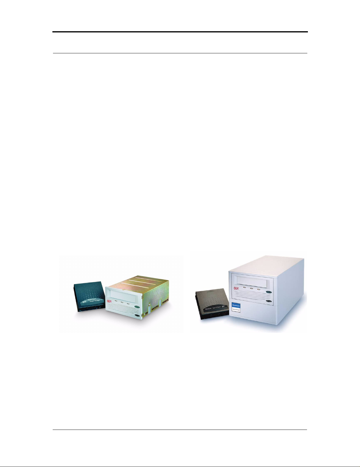
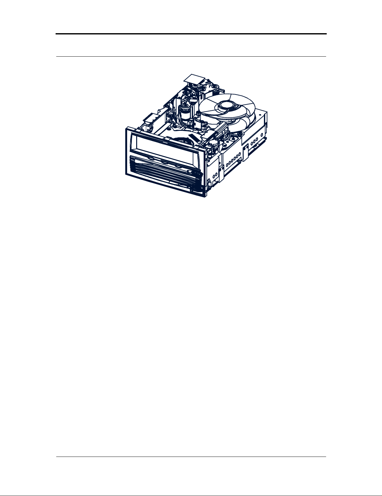
• “SDLT 220/320 Technology” includes photographs of the tape drive, and
introduces important basic features.
• “SDLT 220/320 Modular Design” introduces tape drive components such as
the tape heads, media, cartridge, and host interface.
• “Key Differences Between the SDLT 220 and the SDLT 320” compares
important features in the SDL T 220 and 320 products.
• “Quantum Diagnostics Tools ” describes tools and utilities that provide the
ability to run diagnostics and test for drive functionality .
• “TapeAlert” describes a built-in tape device status monitoring and messaging
utility.
2.1 Overview
The Quantum Super DLTtape™ (SDLT) System is a highly scalable tape drive
designed for multiple product generations. It is a follow-on to the DLT product
family, which remains the industry standard for mid-range UNIX and NT system
backup and archive applications. The SDLT system comprises both the drive and
the tape cartridge; the system is available in either a built-in (internal) model or a
tabletop model. The model SDL T 220 system provides 110 GB of storage capacity
with a transfer speed of 11MB/second (native); the model SDLT 320 system
81-8500 2 - 01 March 20 04 2-1
Page 22

CHAPTER 2: SD LT 220/320 Produc t I nfo rm ation SDLT 220 and SDLT 320 Prod uc t Ma nu al
provides 160 GB of storage capacity with a transfer speed of 16MB/second
(native).
To view a succinct comparison of the two models, refer to “Key Differences
Between the SDL T 220 and the SDLT 320” on page 2-11. For detailed engineering
specifications (for both the SDL T 220 and 320), refer to CHAPTER 3, “Drive
Specifications.”
2.2 SDLT 220/320 Product Feature s
SDLT tape drives offer the following product features:
• A streaming tape drive that uses half-inch wide Digital Linear Tape (DLT)
media.
• Standard 5.25-inch full-height form factor to simplify integration into system
and tape library solutions.
• The SDLT archi tectur e builds on the DLT legacy by offering backward
compatibility: data backed up today using the DLT 8000, DLT 7000, DLT
4000, and DLT 1 (Benchmark) systems will be retrievable in the future using
SDLT-based systems with DLTtape IV type media.
• Global Storage Link (GS Link) — An infrared (wireless) interface that
provides a wireless remote testing base allowing customers and integrators to
access system diagnostic information from the front of the tape system.
• When needed, the SDLT 320 can be operated in a mode that is completely
compatible with that of the SDLT 220.
• Handle-free load and unload feature to increase ease of use.
To see pictures of this product, refer to Figure 2-1 on page 2-3. For a complete
SDLT 220/320 feature comparison, refer to Table 2-1 on page 2-11.
2-2 March 20 04 81-850 02-01
Page 23
SDLT 220 and SDLT 320 Produ ct Manual CHAPTER 2: SDLT 220/320 Product Information
2.3 SDLT 220/320 Technology
SDLT incorporates various new state-of-the-art technologies that contribute to the
SDLT architecture. Some of these ideas are trademarked, others are patented. The
following subsections introduce the important technologies that together , comprise
the SDLT tape drive system.
2.3.1 Laser Gu ide d M agnetic Reco rdi n g
The SDLT system (Figure 2-1 and Figure 2-2) is based on Quantum’s Laser
Guided Magnetic Recording (LGMR) technology. LGMR provides a unique
combination of the best optical and magnetic technologies, which results in
dramatically higher capacities by substa ntially inc reasing the number of recording
tracks on the data-bearing surface of the media. By recording data magnetically on
the data-bearing side of the media and servoing optically on the backside, LGMR
optimizes highly proven technologies to deliver the most efficient, reliable and
scalable data backup solution to the mid-range market.
Internal model
Figure 2-1. SDLT 220/320 Drive System (Photographs)
81-85002-01 March 2004 2-3
Tabletop model
Page 24
CHAPTER 2: SD LT 220/320 Produc t I nfo rm ation SDLT 220 and SDLT 320 Prod uc t Ma nu al
Figure 2-2. SDLT 220/320 Dri ve System (CAD Diagram in Perspective)
2.3.2 Pivoting Optical Servo
Pivoting Optical Servo (POS) is a Quantum-invented, optically-encoded servo
system, which combines high-density magnetic read/write data recording with
laser servo guiding. The POS is designed for high-duty-cycle applications, which
decreases cost and increases user convenience. The POS enables the head to track
dynamic variations in tape motion which allows Quantum to provide a track count
with an order of magnitude increase over current DLT products.
2.3.3 Magneto Resistive Cluster Heads
Magneto Resistive Cluster (MRC) heads are a densely packed array of small, costeffective Magneto Resistive (M R ) tape heads precisely positioned using advanced
thin-film processing technology. SDLT MRC heads provide high wafer usage
efficiency resulting in low head costs, are less susceptible to temperature and
humidity, yield higher track density and capacity, and provide a multi-channel
architecture for increased transfer rate and performance.
2-4 March 20 04 81-850 02-01
Page 25

SDLT 220 and SDLT 320 Produ ct Manual CHAPTER 2: SDLT 220/320 Product Information
2.3.4 A dvanced Partial Response Max imum Likelihood
Improving on Partial Response Maximum Likelihood (PRML) technology
traditionally used in disk drives and communication systems, Quantum’s advanced
PRML channel technology was co-developed with Lucent Technologies to bring
new levels of performance and capacity to high-performance linear tape products.
This provides high-encoding efficiency recording de nsities for gre ater capacity
and performance that enables SDLT to substantially increase transfer rates and
capacity.
2.3.5 Advanced Metal Powder Media
Advanced Metal Powder (AMP) media is a state-of-the-art media using durable
metal powder technology for recording very high densities of data. The back side
of the AMP media receives a specially formulated coating to accept the optical
servo tracks. Because the servo information is on the back side of the media, the
entire data-bearing side of the media is available for recording data and eliminate
the need for pre-formatting. In addition, AMP media has been designed to meet the
needs of multiple generations of the SDLT technology.
2.3.6 Positive Engagement
Positive engagement is a highly robust tape leader-buckling mechanism that
increases cartridge life and supports the heavy duty-cycle environments found in
high-end and automation environments.
This mechanism engages the tape leaders upon cartridge load and disengages them
upon cartridge unload. It uses a solid metal pin that is attached to the drive leader
to link with molded clips that are permane ntly attached to the ta pe leader inside the
cartridge. The Positive L eader Link design makes the buckling of Super DLTtape I
media a totally reliable mechanical process.
In addition to supporting Super DL Ttape I data cartridges, the buckling mechanism
also supports existing DLTtape IV data cartridges to ensure complete backwardread compatibility.
81-85002-01 March 2004 2-5
Page 26
CHAPTER 2: SD LT 220/320 Produc t I nfo rm ation SDLT 220 and SDLT 320 Prod uc t Ma nu al
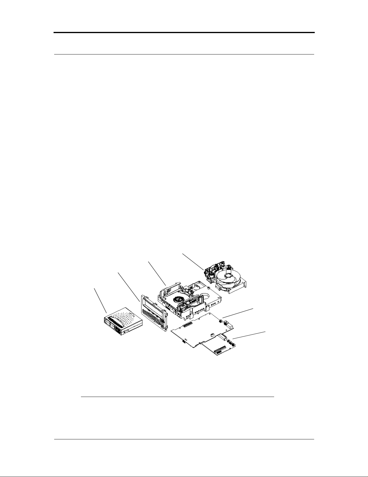
2.4 SDLT 220/320 Modular Design
SDLT is designed as a total system. The system includes a complex interaction of a
number of important components including such items as the tape path, tape heads,
media, cartridge, and host interface.
SDLT is organized into five distinct modules (Figure 2-3) as follows:
• Data Control Module (DCM)
• Tape Control Module (TCM)
• Front Panel Module (FPM)
• Electronic Interface Module (EIM)
• Super DLTtape I Data Cartridge
The modular concept makes the SDLT system easy to manufacture and configure.
Each module is optimized to perform a specific set of functions and designed to
interface with the other modules in a well-defined and flexible manner. The
following subsections provide a brief overview of each module.
DCM
TCM
FPM
Data
Cartridge
EIM ICM
EIM HIM
Figure 2-3. SDLT 220/320 Modular Design
NOTE: Despite the deliberate modularity of each module, with the
exception of the data cartridge and the FPM, individual
users should not “swap” modules. The data cartridge and
2-6 March 20 04 81-850 02-01
Page 27

SDLT 220 and SDLT 320 Produ ct Manual CHAPTER 2: SDLT 220/320 Product Information
the FPM are the only two modules that are field
replaceable. Customer adjustments to the TCM, DCM, or
EIM are not allowed, and will void the drive’s warranty.
2.4.1 D at a C ont rol Modul e
The Data Control Module (DCM) contains several of the functions and features of
Quantum’s LGMR technology, which is at the heart of the SDLT technology. Of
the five technologies that constitute the LGMR technology, two are found in the
DCM. These are the POS and the MRC heads.
The main functions of the DCM are to provide the path and guides for all the tape
motion inside the drive and to write data to and read data fr om the tape. In addition
to the POS and MRC heads described in Section 2.3.2, “Pivoting Optical Servo”
on page 2-4 and Section 2.3.3, “Magneto Resistive Cluster Heads” on page 2-4,
the DCM contains a number of components that interact to perform these
functions. These components include the advanced head guide assembly, take-up
reel, drive motor, the optical servo system, and the tape heads.
The SDLT system tape path, from the first tape guide through the take up reel and
motor, has been simplified and improved from the previous DLT systems. The
addition of servo technology in the POS system has allowed Quantum engineers to
reduce the number of tape guides from six to four. This provides a simpler tape
path in the SDLT tape drive, improving performance and reliability.
In addition to its mechanical components, the DCM also contains printed circuit
boards that control the functions of the DCM and the tape heads.
81-85002-01 March 2004 2-7
Page 28

CHAPTER 2: SD LT 220/320 Produc t I nfo rm ation SDLT 220 and SDLT 320 Prod uc t Ma nu al
2.4.2 Tape Control Module
The T ape Control Module (TCM) implements the functions required to buckle and
unbuckle the tape and control the tape motion. The TCM consists of a variety of
components:
• TCM PCBA (Printed Circuit Board Assembly)
• Base Plate
• Cartridge Receiver
• Positive Engagement Tape Leader Buckling Mechanism.
Other components include the tape supply motor assembly and the floor plate
assembly.
TCM PCBA
The TCM has its own Printed Circuit Board Assembly (PCBA) that controls the
functions of the TCM and interfaces with the main controller board in the EIM. By
designing the TCM as a distinct module, it allows the TCM to be manufactured
and tested as a stand-alone module, simplifying the design, manufacturing and
troubleshooting processes.
Base Plate
The SDLT base plate is an aluminum die casting with precisely machined surfaces
that acts as the support platform for the other modules and for the drive enclosure.
The base plate also includes the precision mounting holes used to install SDLT
tape drives into a server or tape library. The SDLT base plate, and therefore the
entire SDLT drive, conforms to the 5.25 inch, full-height form factor. This means
that SDLT tape drives are a little shorter , at the s tandard 8 inche s, than the previou s
generation DLT products.
Cartridge Receiver
On tape insertion, the cartridge receiver assembly guides the tape into its operating
position, opens the cartridge door, unlocks the cartridge brakes, engages the
cartridge drive motor, and secures the tape for operation. On tape ejection, the
2-8 March 20 04 81-850 02-01
Page 29

SDLT 220 and SDLT 320 Produ ct Manual CHAPTER 2: SDLT 220/320 Product Information
cartridge receiver assembly reverses the process and automatically ejects the tape a
fixed distance from the front of the drive. There is no longer a manual lock and
release handle to operate when loading and unloading the cartridge. This “soft
load” capability makes SDLT easier for customers to use in both stand-alone
applications and automated tape libraries.
Positive Engagement Tape Leader Buckling Mechanism
This design for SDLT uses a solid metal pin attached to the drive leader which
positively links with molded clips that are permanently attached to the tape leader
inside the cartridge. The buckling mechanism is responsible for engaging the tape
leaders upon cartridge load and disengaging them on cartridge unload.
The SDLT buckling mechanism has been designed to work with the new leaders of
the Super DLTtape design as well as the leaders of the previous DLTtape design,
allowing backward-read compatibility (BRC) of DLTtape IV cartridges in the
SDLT system.
2.4.3 Front Panel Module
The Front Panel Module (FPM) of the system (sometimes referred to as the bezel)
performs a number of functions. The functions of the SDLT FPM include:
• Protecting the front of the TCM from physical damage
• Channeling airflow through the system
• Aligning the cartridge when it is inserted into the system
• Providing system status and information through LEDs
• Enabling cartridge ejection
• Delivering the overall cosmetic look of the system.
The FPM is a single module with lenses for the system’s LEDs and a button to
activate the drive eject switch. Unlike previous generations of DLT, the SDLT
front panel contains no electronics.
81-85002-01 March 2004 2-9
Page 30

CHAPTER 2: SD LT 220/320 Produc t I nfo rm ation SDLT 220 and SDLT 320 Prod uc t Ma nu al
2.4.4 Electronic Interface M odule
The Electronic Interface Module (EIM) is the electronic heart of the SDLT system.
It provides the main control function for the system and the interface from the
system to the host computer. The EIM provides the Advanced PRML feature of
Quantum’s SDLT technology; advanced PRML is described in “Advanced Partial
Response Maximum Likelihood” on page 2-5.
The EIM consists of two major boards: the Integrated Controller Module (ICM),
and a separate Host Interface Module (HIM). The ICM contains the main
controller and servo micro-processor, the custom-designed SDLT ASICs and the
cache memory while the HIM implements the interface between the host system
and the drive. This allows easy configuration of the drive to match different host
interfaces by simply substituting the appropriate HIM card.
As with the other major modules of the SDLT technology, the EIM has been
designed to be manufactured and tested as a distinct module.
2.4.5 S uper DLTtape I Data Ca rt ri dge Module
As with all tape technologies, the Super DLTtape I data cartridge is a key part of
the overall system. The main function of the data cartridge is to provide the
magnetic recording media used by the system to store customer information. The
data cartridge also provides the protective cartridge that allows the media to be
removed and stored safely.
From the outside, the Super DL Ttape I data cartridge looks very similar to the
DLTtape IV data cartridges. The basic geometry, write protection switch, and label
space are unchanged from the DLTtape IV data cartridge. This simplifies the
integration of SDLT into existing operating environments and into automated tape
libraries. The Super DLTtape I data cartridge is easy to recognize; it has a different
color than the DLTtape IV data cartridge and contains a distinctive pattern molded
into the shell.
The Super DLTtape I data cartridge has a new, more rugged design that includes a
thicker internal circular wall surrounding the media and more structural ribbing to
increase overall cartridge resilience and reduce potentia l damage to the cartridge if
it should be dropped. New, wear-resistant materials reduce the potential for debris
generation and increase the life of the cartridge.
2-10 March 20 04 81-850 02 - 01
Page 31

SDLT 220 and SDLT 320 Produ ct Manual CHAPTER 2: SDLT 220/320 Product Information
2.5 Key Differences Between the SDLT 220 and the SDLT 320
Table 2-1 compares important features in the SDLT 220 and the SDLT 320
products.
Table 2-1 . A Comparison of SDLT 220 and SDLT 320 Features
Feature SDLT 220 SDLT 320
Capacity
Compressed
Uncompr essed
Data Transfer Rate
Compressed
Uncompr essed
‡
‡
220 GB
110 GB
22 MBp s
11 MBps
320 GB
160 GB
32 MBps
16 MBps
Media Compatibility Super DLTtape I
DLTtap e IV ( R ead O n ly )
DLT 1 by Benchmark:
TRS13 Model (Read Only)
‡ The compression rates shown assume an indu stry standard 2:1 compression ratio. Actual compressio n ratios
achieved depend on the redundancy of data file s being recorded.
Miscellaneous Product Features
Tape Speed 116 ips 122 ips
Linear Density 133 Kbpi 193 Kbpi
Cache S iz e 32 MB 64 MB
Interfa ces Available
Ultra 2 SCSI, LVD
Ultra 2 SCSI, HVD
Super DLTtape I
DLTtape IV (Read Only)
DLT 1 by Benchmark
(Read Only)
Ultra 2 SCSI, LVD
Ultra 2 SCSI, HVD
81-85002-01 March 2004 2-11
Page 32

CHAPTER 2: SD LT 220/320 Produc t I nfo rm ation SDLT 220 and SDLT 320 Prod uc t Ma nu al
2.6 Quantum Diagnostics Tools
Quantum frequently provides new and updated tools to use with its tape drives. For
example:
SDLT Update This utility is a SCSI-based Windows
application that allows you to load tape drive
firmware and create code upload tapes.
GSLink Allows you to quickly diagnose the integrity
of the drive using an infrared (wireless)
communication connector located on the front
panel of the tape drive.
Pocket
GSLink
Density Select A utility that enables you to specify that your
All tools are available on Quantum’s web site, http://www.quantum.com. New
tools and utilities get added frequently. Follow the path Support =>Drivers and
Software and look at the list to see what is available.
Allows you to diagnose the integrity of a
Super DLTtape drive using your Pocket PC.
This application uses infrared (wireless)
communication between your Pocket PC and
the Super DLTtape drive. Pocket GSLink runs
on the Pocket PC 2002 operating system.
SDLT 320 tape drive write data cartridges that
are backward compatible with your SDL T 220
tape drives.
2-12 March 20 04 81-850 02 - 01
Page 33

SDLT 220 and SDLT 320 Produ ct Manual CHAPTER 2: SDLT 220/320 Product Information
2.7 TapeAlert
SDLT drives are delivered with TapeAlert features built in. The internal SDL T
firmware constantly monitors the device’s hardware and media, checking for
errors and potential difficulties. Any problems identified are flagged on the SCSI
log page, where 64 bytes have been reserved for use by T apeAlert.
After a backup has been completed, the TapeAlert-compatible backup application
will automatically read the device’s TapeAlert SCSI log page to check for any
problems. If an error is flagged, your backup software displays a clear warning
message on your screen, and adds the TapeAlert messages to its logs. These
messages are standard across all applications that support TapeAlert, and are
designed to give clear explanation of the problem and suggested resolution. For
example, if you were attempting to back up onto an expired tape, you would see
the following message:
WARNING: The tape cartridge has reached the end of its useful life:
Copy any data you need to another tape.
Discard the old tape.
81-85002-01 March 2004 2-13
Page 34

CHAPTER 2: SD LT 220/320 Produc t I nfo rm ation SDLT 220 and SDLT 320 Prod uc t Ma nu al
2-14 March 20 04 81-850 02 - 01
Page 35

CHAPTER 3 Drive Specifications
This chapter describes various specifications that apply to the Quantum
Super DLTtape system, which include:
• “Product Specifications” provides the product specifications for the SDLT
220/320 tape drives.
• “Functional Specifications” provides the functional specifications for the
SDLT 220/320 tape drives.
• “Environmental Specifications” provides the environmental specifications for
the SDLT 220/320 tape drives.
• “Recording Media Specifications” provides the media specifications for Super
DLTtape I and DL T tape IV data cartridges.
3.1 Product Specifications
The following subsections contain full product specifications for the Quantum
SDLT 220/320 tape drives.
81-8500 2 - 01 March 20 04 3-1
Page 36

CHAPTER 3: Dr iv e Specifica t io n s SDLT 220 and SDLT 320 Prod uc t Ma nu al
3.1.1 Interface Type
The SDLT drive is available in either of two possible SCSI interface versions;
these versions provide three possible SCSI interface types:
• Multimode Single-Ended (MSE) provides one of two interfaces:
Low Voltage Differential (LV D) running at 80 MB/second, or
Si ngle Ended (SE) running at 40 MB/second.
• High Voltage Differential (HVD) running at 40 MB/second.
NOTE: By default, the SDLT system is shipped with a wide SCSI
configuration that you can convert to narrow SCSI, if you
wish. For details, refer to “Configuring the Internal Drive
for Narrow SCSI” on page 4-11.
3.1.2 Physical Dimensions
Table 3-1 provides physical dimensions for the SDLT system.
Table 3-1 . SDLT 220/320 Physical Dimensions and Shipping Weight
Description Internal Version Tabletop Version
Height
Width
Depth
Weight* 2.38 kg (5 lbs. 4 oz) 6.27 kg ( 13 lbs. 13 oz)
Shipping
Weight*
* Weights depend on configurati on. The packaging used may change th e shipping weight.
Note: Mounting hole pattern for the bottom and sides of the system is industry standard.
82.55 mm (3.25 in) without front bezel;
85.73 mm (3.38 in) with front bez el
146.05 mm (5.75 in) behind front bezel;
148.59 mm (5.85 in) with front bezel
203.20 mm (8.00 in) measured from back of front
bezel; 212.73 mm (8.38 in) including front bezel
3.77 kg (8 lbs. 5 oz) 9.90 kg ( 21 lbs. 13 oz)
164.46 mm (6.48 in)
174.75 mm (6.88 in)
320.04 mm (12.60 in)
3-2 March 20 04 81-850 02-01
Page 37

SDLT 220 and SDLT 320 Product Manual CHAPTER 3: Drive Specifications
3.1.3 Storage Capacity
Table 3-2 provides native and compressed capacity ranges for the Super DLTtape I
data cartridge:
Table 3-2 . SDLT 220/320 Storage Capacity
SDLT 220 SDLT 320
Native Storage Capacity 110 GB 160 GB
Compressed Storage
Capacity
220 GB
(2:1 compression ratio)
In accordance with industry practice, a typical compression ratio of 2:1 is quoted.
Actual compression ratios achieved depend on the redundancy and type of data
files being written.
3.1.4 Compression
The drive contains on-board hardware to compress and decompress data using a
DLZ algorithm. The default setting for data compression is ON.
3.1.5 Data Integrity
SDLT data transfer errors are extremely rare; data integrity for the overall tape
system is shown in Table 3-3.
320 GB
(2:1 compression ratio)
Table 3-3 . Data Transfer Error Rates
Error Type Frequency
Detected, Recoverable (ECC) READ
Detected, Unrecoverable READ
Undetected READ
Rewrite of Data
81-85002-01 March 2004 3-3
<1 error in 10
<1 error in 10
<1 error in 10
<5 per 10
6
bytes read
17
bits read
27
bits read
6
bytes written
Page 38

CHAPTER 3: Dr iv e Specifica t io n s SDLT 220 and SDLT 320 Prod uc t Ma nu al
3.1.6 Ma xi m u m D at a Trans fe r Rat e
The maximum sustained (and burst) data transfer rates for SDLT drives are shown in
Table 3-4.
Table 3-4 . Maximum Data Tr ansfer Rates
Config-
Native
SDLT 220
Sustained
SDL T 220
Compressed‡ Native
Burst
Max*
SDLT 320
Sustained
SDL T 320
Compressed‡
uration
HVD
(Ultra 1
SCSI)
LVD
(Ultra 2
SCSI)
* Burst speeds are limited by the SCSI bus itself, not the design of SDLT 220/320 or Super DLTtape media.
‡ The compression rates shown assume an indu stry standard 2:1 compression ratio. Actual compressio n ratios
Narrow 11 MB/sec 20 MB/sec 20 MB/sec 16 MB/sec 20 MB/sec 20 MB/sec
Wide 11 MB/sec 22 MB/sec 40 MB/sec 16 MB/sec 32 MB/sec 40 MB/sec
Narrow 11 MB/sec 22 MB/sec 40 MB/sec 16 MB/sec 32 MB/sec 40 MB/sec
Wide 11 MB/sec 22 MB/sec 80 MB/sec 16 MB/sec 32 MB/sec 80 MB/sec
achieved depend on the redundancy of data files being recorded. For non-compressible (expanding) data, this
results in a reduction in capacity and transfer rate for the data. Fully random data is the worst case for
compressibility.
Burst
Max*
NOTE: Cable lengths and cable type can limit attainable transfer
rate; for details, refer to a separate document ,
SDLT 220 and SDLT 320 Design and Integration Guide,
81-81148-01.
3.1.7 Head Life and MTBF
Mean time between failures (MTBF) for the overall tape system is projecte d to be
250,000 hours, not including the heads. Head life is a minimum of 30,000 tape
motion hours and an average of 50,000 tape motion hours.
3-4 March 20 04 81-850 02-01
Page 39

SDLT 220 and SDLT 320 Product Manual CHAPTER 3: Drive Specifications
To provide access to backup tapes written on DLTtape tape drives, the SDLT drive
will read, but not write, DLTtape IV cartridges; this is known as backward-read
compatibility (BRC) mode. The drive uses a different head while operating in
BRC mode; the BRC head life is guaranteed to be a minimum of 10,000 tape
motion hours.
NOTE: Quantum Corporation does not warrant that predicted
MTBF is representative of any partic ular unit ins ta lled for
customer use. Actual figures vary from unit to unit.
3.1.8 Media Durability
Media durability is 1,000,000 passes; a media pass is defined as movement of the
tape head over the surface of the media (in either direction). Alternatively stated,
each DLTtape IV and Super DLTtape I media provides 250 full tape uses; a full
tape use (end-to-end) is considered to be the type of operation that occurs when a
customer writes very large filesets to the tape.
3.1.9 C ar trid g e Life Expectan cy
Table 3-5 shows the number of load and unload cycles you can expect before the
tape cartridges need to be replaced.
Table 3-5 . Loading and Unloading the Media Cartridge (Maximum)
DLTtape IV
Tape Cartridge
Cartridge load/unload cycles† 10,000 100,000
Tape insertions
† Load and unload cycles are rated at 5,000 for the cartridge itself.
‡ An insertion is when a tape is inserted into the r eceiver, loaded to BOT,
calibrated, and then unl oaded.
‡ 5,000 5,000
Super DLTtape I
Tape Cartri dge
81-85002-01 March 2004 3-5
Page 40

CHAPTER 3: Dr iv e Specifica t io n s SDLT 220 and SDLT 320 Prod uc t Ma nu al
3.1.10 Posit iv e Engagement Tape Leader Buckling Mechanism
This buckling mechanism is responsible for engaging the tape leaders upon
cartridge load and disengaging them upon cartridge unload. The Super DLTtape I
tape buckling mechanism has been designed to work with the new leaders of the
SDLT tape drive design as well as the leaders of the previous DLT drive design,
allowing backward-read compatibility of DLTtape IV cartridges in the SDLT tape
drive system.
Component level tests of buckle arm components have shown at least 250,000
cycles on an SDL T drive without failure, breakage, or binding; this includes the
take-up leader, the supply leader, and the media itself.
3.2 Functional Specifications
The following subsections contain full functional specifications for the Quantum
SDLT 220/320 tape drives.
3-6 March 20 04 81-850 02-01
Page 41

SDLT 220 and SDLT 320 Product Manual CHAPTER 3: Drive Specifications
3.2.1 S DLT 220/320 Performance Data
Table 3-6 provides performance data for the SDLT system. For a comparison of
SDLT 220/320 storage capacities, refer to Section 3.1.3, “Storage Capacity” on
page 3-3.
Table 3-6 . SDLT 220/320 Performance Data
Feature SDLT 220 SDLT 320
Drive Re ad / Write
Transf er R a te*
Tracks
Track Density 1058 tracks per inch (tpi) Same
Linear Bit Densi ty 133 Kbits per inch (bpi) 193 Kbit s per inch (bpi)
Read / Write Ta pe Speed 116 inches per second (ips) 122 inches per second (ips)
Rewind Tape Speed 160 ips Same
Linear Search Tape Speed 160 ips Same
Average Rewind Time 69 seconds Same
Maximum Rewind Time 140 seconds Same
Average Access Time
(from BOT)
Maximum Access Time
(from BOT)
Load to BOT
11 MB/second, native 16 MB/second, native
56 logical tracks;
448 physical tracks
70 seconds Same
142 seconds Same
12 seconds (typical)
40 seconds (unformatted tape)
Same
Same
Unload from BOT 12 seconds Same
Nominal Tape Tension
* Dependin g on data type and SCSI bus li mitations/system configur ation.
Note th at data is typical; times may be longer if error recovery time is ne eded.
81-85002-01 March 2004 3-7
Stationary = 3.0 ± 0.5 oz
Operating Speed = 3.5 ± 0.5 oz
Same
Page 42

CHAPTER 3: Dr iv e Specifica t io n s SDLT 220 and SDLT 320 Prod uc t Ma nu al
3.2.2 Shock and Vibration Specifications
The following tables provide non-operating and operating shock and vibration
specifications for the SDLT system.
Table 3-7 . Non-Operating Shock Specifications (Unpackaged)
Shock (Un pa ck a ged)
Pulse Shape
Peak Accelerati on 40 G 140 G
Duration 10 ms (180 inches/second) 2 ms
Appli ca ti o n X ,Y,Z axes, twic e in each axis ( o nc e in ea ch di r ection)
Square wave ½ sine pulse
Table 3-8 . Non-Operating Shock Specifications (Packaged, Drop)
Shock (Packaged,
Drop)
Drop
Height
of Drop
42 inches
36 inches
Number
of Drops Package Weight
16 drops total
16 drops total
0 lbs. < package weight
20 lbs. < package weight
≤ 20 lbs.
≤ 50 lbs.
3-8 March 20 04 81-850 02-01
Page 43

SDLT 220 and SDLT 320 Product Manual CHAPTER 3: Drive Specifications
Table 3-9 . Non-Operating Vibration Specifications
Vibration (Unpackaged)
Type
Frequency Range 5 - 500 - 5 Hz Upward and downward sweep
Acceleration Leve l
Application X,Y,Z axes Sweep rate = ½ octave /minute
Sine Sweep
0.02" DA
1.0 G
Between 5 and 31 Hz (crossover)
Between 31 and 500 Hz (crossover)
Type Random
Frequency Range 10 - 500 Hz
Acceleration Leve l 2. 0 G
PSD Envelope
Application X,Y,Z axes Sweep rate = 60 minutes / axis
0.008 G
2
/Hz
Vibration (Packaged)
Type
Frequency Range
Application
Random
Truck Pro f ile* (0.5 Grms)
Air Profile* (1.0 Grms)
X,Y,Z axes (30 minutes, each profile and each axis, for a total of 3
hours)
Type
Frequency Range 5 - 150 - 5 Hz ; 0.5 octave /minute, 0.5 G
Application
* Air and truck profile s ar e spec ified in ASTM D4728, Standard Test Method for Random
Vibration Testing of Shipping Containers.
81-85002-01 March 2004 3-9
Sine, Sweep, and Dwell
X,Y,Z axes; dwell at lowest resonant frequency in axis for 30
minutes.
Additional 30 minu tes for each additional resonance; up to 4
resonances total .
Page 44

CHAPTER 3: Dr iv e Specifica t io n s SDLT 220 and SDLT 320 Prod uc t Ma nu al
Table 3-1 0. Operating Shock and Vibration Specifications
Shock
Pulse Shape
Peak Acceleration 10 G
Duration 10 ms
Application X,Y,Z axes, twice in each axis (once in each direct ion)
Vibration
Type
Frequency Range 5 - 500 - 5 Hz Upward and downward sweep
Acceleration Leve l
Applicat ion X,Y,Z axes Sweep rate = 1.0 octave per minute
½ sine pulse
Sine Sweep
0.25 G
0.010" DA
Between 22 and 500 Hz
Between 5 and 22 Hz (crossover)
3.2.3 Current and Power Requirements
T able 3-1 1 on page 3-11 lists the current and power requirements for both versions
of the tape system (internal and tabletop). The tabletop version requires AC power .
The highest current (and power) is drawn during the native write modes and
backward-read compatibility (BRC) rea d modes, so they are outlined in
Table 3-11. Standby is measured with the tape loaded and tensioned or
untensioned, and Idle is measured with power on with no tape loaded. (The
power drawn in these two modes is similar enough that they are listed together.)
Power-up current surges are less than those encountered during motor
accelerations, and so are not listed separately .
NOTE: In Table 3-11, the current and DC power values are
relevant to the internal drive, while the AC power values
are relevant to the tabletop drive.
3-10 March 20 04 81-850 02 - 01
Page 45

SDLT 220 and SDLT 320 Product Manual CHAPTER 3: Drive Specifications
Table 3-11. Current and Power Specifications
Mode
5 V Current (A)
1
MaxPk
MaxRms
2
Typ
12 V Current (A)
MaxPk
3
1
MaxRms
DC Power (W)
4
2
Typ
Max
3
Typ
AC Power (W)
6
Max
5
Standby / Idl e 3.2 3.0 2.9 0.6 0.5 0.4 20 19 34 29
Media Load i n g
/ Unloading
220/320 Write–
Motor Start
8
220/320 Write–
Streaming
Max for SDLT
9
Modes
BRC Read–
Motor Start
8
BRC Read–
Streaming
Max for BRC
9
Modes
3.8 3.1 2.9 4.8 1.0 0.7 25 24 38 33
6.1 3.1 3.0 4.8 1.0 0.7 25 24 33 30
6.3 4.3 3.8 2.1 0.7 0.7 28 27 42 38
4.3 1.0 28 42
3.9 3.0 2.8 2.3 0.7 0.6 23 22 38 32
5.2 3.3 3.1 1.8 0.7 0.6 24 22 41 33
3.3 0.7 24 41
Typ
7
1. The Max-Peak value represents short current spik es drawn for durations of < 50us. On the 12V s upply , the peaks
corres pon d to the puls e wi dth modul at ed sw itchi ng of t he mot or s. Thes e val ue s ar e calc ul ate d from th e aver age of
Peak-ripple-current + 2 sigma, measured at +5% DC voltage.
2. The Max-Rms value is the average of the maximum R MS current drawn during this op erating mode. These
values are calculated from the average of RMS current + 3 sigma, measured at nominal DC vol tage.
3. The typical current is calculated from the average of all RMS current drawn during this operat ing mode,
measured at nominal DC voltage.
4. The Max DC power is calculated from the typical DC power + 3 sigma, measured at nominal DC voltage. This
value takes into account that the peak currents on the 5V and 12V do not occur at the same time.
5. The T ypical DC power is calculated from the average RMS DC power drawn during this operating mo de,
measured at nominal DC voltage. This value also takes into account that th e peak current s on the 5V and 12V do
not occur at the same time.
6. The Max AC power is calculated fr om the typical AC powe r in tabletop dri ves + 3 sigma.
7. The T ypical AC power is calculated from the averag e of A C pow er drawn in tabletop drives.
8. The motor start modes dr aw the most current from the 12V supply, so they are shown separatel y. These events
last < 1 second and occur at a duty cycle of less than 25%.
9. The Max values for each mode are based on the Max-rms values, si nce the peak va lues are of very short duration.
81-85002-01 March 2004 3-11
Page 46

CHAPTER 3: Dr iv e Specifica t io n s SDLT 220 and SDLT 320 Prod uc t Ma nu al
3.2.4 Tape System Recording Method
The SDLT 220 tape system uses the Partial Response Maximum Likelihood
(PRML) 32/33 encoding method for reading/writing SDLT format.
The SDLT 320 tape system uses the PRML 32/33 encoding method for reading/
writing SDLT 320 and 220 format.
3-12 March 20 04 81-850 02 - 01
Page 47

SDLT 220 and SDLT 320 Product Manual CHAPTER 3: Drive Specifications
3.3 Environmental Specifications
The SDLT 220/320 tape drive operates in environments that include general
offices and workspaces with systems capable of maintaining standard comfort
levels.
The following subsections provide the environmental specifications for the SDLT
systems (both the internal and the tabletop configurations). For long-term troublefree operation, it is strongly recommended that SDLT tape drives be used in a
clean, smoke-free environment.
3.3.1 Air Flow Requirements
Adequate air flow must be provided for the internal tape drive to dissipate the heat
resulting from continuous drive operation. Specifically, the air flow must be
sufficient to keep the tape path temperature below 52°C.
NOTE: It is important to realize that the amount of air flow
provided for the tape drive determines the maximum
ambient temperature in which the drive can operate.
For more details about specific temperatures inside the drive at specific locations,
refer to a separate document, SDLT 220 and SDLT 320 Design and Integration
Guide, 81-81148-01.
81-85002-01 March 2004 3-13
Page 48

CHAPTER 3: Dr iv e Specifica t io n s SDLT 220 and SDLT 320 Prod uc t Ma nu al
3.3.2 Temp er ature and Hu m id ity
The ambient operating e nvironment for the tape drive may not exceed the limits shown in
Table 3-12. (The specifications shown in the table are valid for both the internal and
tabletop tape drives
Table 3-1 2. Temperature and Humidity Specification
Specification Operating Limits
Wet Bulb Temperature 25°C (77°F) 25°C (77°F)
.)
Non-Operating Limits
(Power On ; N o Tape
Loaded)
Dry Bulb T empera ture
Range
Temperature Gradient 11°C (20°F) / hour (across range) 15°C (27°F) / hour (across range)
Relative Humidity 20% to 80% (non-conde nsing) 10% to 90% (non-condensing)
Humidity Gradie nt 10% / hour 10% / hour
10°C to 40°C (50°F to 104 °F) 10°C to 40°C (50°F to 104°F)
3.3.3 Storage and Shipment
The ambient storage and shipment environment for the tape drive may not exceed the
limits shown in
the internal and tabletop tape drives
Table 3-1 3. Drive Storage and Shipment Specifications
Specification
Wet Bulb Temperature 46°C (114°F) 46°C (114°F)
Dry Bulb Temperature -40°C to 66°C (-40°F to 150°F) -40°C to 66°C (-40°F to 150°F)
Table 3-13. (The specifications shown in the table are valid for both
.)
Storage
(Unpacked or Packed) Shipping
Temperature Gradient 20°C (36°F) / hour (a cros s range) 20°C (36°F) / hour (acr os s range)
Relative Humidity 10 to 95% (non-condensing) 10 to 95% (non-condensing)
Humidity Gradie nt 10% / hour 10% / hour
* Note that these specifications apply to the tape drive only. Media specifications are listed in
“Recording Media Specifications” on page 3-15.
3-14 March 20 04 81-850 02 - 01
Page 49

SDLT 220 and SDLT 320 Product Manual CHAPTER 3: Drive Specifications
3.3.4 Altitude
Both the internal and tabletop tape drives operate in normal pressures from –500 to
10,000 feet when operated within the ambient operating environments specified in
“Temperature and Humidity” on page 3-14.
The drive will operate to 30,000 feet for temperatures within 15 ± 5 °C.
3.3.5 Particulate Contamination Limits
The ambient operating environment for the tape drive may not exceed the
particulate counts shown in Table 3-14.
Table 3-1 4. Particulate Contamination Limits
Particle Size
(microns)
0.1
0.5
5.0
Number of Part ic l es ≥
Particle Size per
Cubic Meter
8.8 x 10
3.5 x 10
2.5 x 10
7
7
5
Num b er of Pa r ticles ≥
Particle Si ze per
Cubic Foot
2.5 x 10
1.0 x 10
7.0 x 10
6
6
3
3.4 Recording Media Specifications
The following tables provide specifications for Super DLTtape I media. Basic
media specifications for the Super DLTtape I are shown in Table 3-15. Operating,
storage, and shipping environment limits for the DLTtape IV cartridges are shown
in Table 3-16.
81-85002-01 March 2004 3-15
Page 50

CHAPTER 3: Dr iv e Specifica t io n s SDLT 220 and SDLT 320 Prod uc t Ma nu al
Table 3-1 5. Super DL Ttape I Media Specifications
Description Specifications
Width 0.5 in.
Magnetic Coating 30 0 nm metal particle
Length 1800 feet (1765 feet usable)
Coercivity 1800 Oe
Cartridge Dimens ions 4.1 in x 4.1 in x 1.0 in
Shelf Life 30 years min. @ 20°C & 40% RH (non-condensing)
Usage 1,000,000 passes (typical office/computer environment)
Cartridge Hous ing Color Dark Green
Table 3-1 6. DLTtape Media Operati ng and Storag e Limits
Oper ating Conditions
Temperature 10° to 40°C (50° to 10 4°F)
Relative Humidity 20% to 80% (non-condensing)
Storage Conditions With Data: Without Data:
Temperature 18° to 28°C (64° to 82°F) 16° to 32°C (61° to 89°F)
Relative Humidity 40% to 60% (non-condensi ng) 20% to 80% (non-condensing)
Shipping C o nd it ion s
Temperature -18°C to 49°C (0°F to 120°F)
Relative Humidity 20 to 80% (non-condensing)
Maximum Wet Bulb
Temperature
Maximum Dew Point 2°C (36°F)
26°C (79°F)
3-16 March 20 04 81-850 02 - 01
Page 51

SDLT 220 and SDLT 320 Product Manual CHAPTER 3: Drive Specifications
3.4.1 B ackward-Read Compa tibi lit y Transf er Rates
Both the SDLT 220 and 320 drives feature an optional backward-read
compatibility (BRC) mode. W hen in BRC mode, the drives are capable of reading
DLTtape IV tapes with DLT 4000, DLT7000, DL T 8000, and DLT 1 formats. The
BRC transfer rates for the SDLT drive are listed in Table 3-17.
Table 3-1 7. Backward-Read Compatibility (BRC) Transfer Rates
Native Read
Format Cartridge Type Native Capacity
(GB)
SDLT 320 Super DLT tape I 160 16.0
SDLT 220 Super DLT tap e I 110 11.0
DLT 8000 DLTtape IV 40 4.0
DLT 7000 DLTtape IV 35 3.5
Transfer R a te
(MB/second)
DLT 4000 DLTtape IV 20 1.5
DLT 1 (Benchmark) DLTtape IV 40 3.0
Notes:
• Transfer rates quoted are nominal, measured reading uncompressed data.
• Non-SDL T dri ves will eject a cartridge written in SDLT 320 format.
• The SDLT 320 can read and write the SDLT 220 format at the native SDLT 220 transfer rate
of 11.0 MB/sec.
81-85002-01 March 2004 3-17
Page 52

CHAPTER 3: Dr iv e Specifica t io n s SDLT 220 and SDLT 320 Prod uc t Ma nu al
3-18 March 20 04 81-850 02 - 01
Page 53

CHAPTER 4 Installing Your Tape Drive
This chapter describes how to install the internal tape drive into a system. This
includes configuration jumper settings, connector pin assignments, installation
instructions, power and signal cabling descriptions, and operating instructions.
This chapter also includes information on configur ing and connecting the tabletop
version of the drive into a system.
This chapter covers the following topics:
• “Safety, Handling, and ESD Protection” describes appropriate guidelines
when working with the tape system.
• “Pre-Installation Guidelines” describes pr oper steps to take bef ore the dr ive is
installed in a system. This includes recording the model and serial numbers,
checking that the proper SCSI controller and cable have been delivered and
checking the drive for proper operation before installing it into a system.
• “Configuring and Installing an Internal Tape Drive” describes how to
configure and install an internal tape drive into a system.
• “Configuring and Installing a Tabletop Drive” describes how to configure and
install the tabletop version of the tape drive.
• “Confirming the Install ation” describes how to confirm that t he drive has been
installed correctly.
81-8500 2 - 01 March 20 04 4-1
Page 54

CHAPTER 4: Ins talling Your Tape Drive SDLT 220 and SDLT 320 Prod uc t Ma nu al
4.1 Safety, Handling, and ESD Protection
Inappropriate or careless handling of tape systems may result in damage to the
product. Follow the precautions and directions to prevent damaging the tape
system. In addition, follow the pre-installation guidelines to ensure that you have
the correct hardware for your system configuration.
4.1.1 Safety Precautions
For your safety, follow all safety procedures described here and in other sections of
the manual.
1. Remove power from the system before installing or removing the tape dri ve to
prevent the possibility of electrica l s hock or damage to the ta pe drive . Unplug
the unit that contains or is to contain the drive from AC power to provide an
added measure of safety.
2. Read, understand, and observe all label warnings.
3. The POS uses a Class I laser product. This laser product complies with 21
CFR 1040.10 as applicable on the date of manufacture.
CAUTION: While the tape drive chassis is open, you can be exposed
to invisible laser radiation; take care to avoid direct
exposure to the beam.
4-2 March 20 04 81-850 02-01
Page 55

SDLT 220 and SDLT 320 Product Manual CHAPTER 4: Installing Your Tape Drive
4.1.2 Handling
Damage to the tape system can occur as the result of careless handling, vibration,
shock, or electrostatic discharge (ESD). For more details about ESD, refer to
“Electrostatic Discharge Protection” on page 4-4.
Follow these guidelines to avoid damage to the drive:
CAUTION: Always handle the tape system with care to avoid
damage to the precision internal components. Do not
place hands inside the tape drive’s receiver area. Hold
the internal tape drive by the sides or the tabletop drive
by the bottom. Never hold either drive by inserting
fingers into the receiver area on the front of the drive.
Damage to the receiver area may occur if the drive is
lifted or carried in this manner.
• Always observe prescribed ESD precautions.
• Keep the internal drive in its anti-static bag until ready to install.
• Always use a properly fitted wris ts tra p or othe r s uita ble ES D protec tion when
handling the drive.
• Hold the internal tape drive only by its sides.
• Do not bump, jar, or drop the drive. Use care when transporting the drive.
• Always handle the drive carefully and gently. A drop of ¼ inch onto a bench
or desktop may damage a drive.
• Never place the tape drive so that it rests on its front bezel. Always gently
place the drive flat, printed circuit board (PCB) side down, on an appropriate
ESD-protected work surface to avoid the drive being accidentally knocked
over.
• Do not pack other materials with the drive in its anti-static bag.
• Place the drive in the anti-static bag before placing it in a shipping container .
• Do not stack objects on the drive.
• Do not expose the drive to moisture.
• Do not place foreign objects inside the tape system’s receiver area.
81-85002-01 March 2004 4-3
Page 56

CHAPTER 4: Ins talling Your Tape Drive SDLT 220 and SDLT 320 Prod uc t Ma nu al
4.1.3 Electrostatic Discharge Protection
Several electrical components of the tape system are sensitive to static electricity
and Electrostatic Discharge (ESD). Even a static buildup or discharge that is too
slight to feel can be sufficient to destroy or degrade a component’s operation.
To minimize the possibility of ESD-related damage to the system, we strongly
recommend using both a properly installed workstation anti-static mat and a
properly installed ESD wrist strap. When correctly installed, these devices reduce
the buildup of static electricity that might harm the system.
Observe the following precautions to avoid ESD-related problems:
• Use a properly installed anti-static pad on your work surface.
• Always use a properly fitted and grounded wrist strap or other suitable ESD
protection when handling the tape system and observe proper ESD grounding
techniques.
• Hold the drive only by its sides. Do not touch any components on the printed
circuit board assembly (PCBA).
• Leave the drive in its anti-static bag until you are ready to install it in the
system.
• Place the drive on a properly grounded anti-static work surface pad when it is
out of its protective anti-static bag.
• Do not use the bag as a substitute for the work surface anti-static pad. The
outside of the bag may not have the same anti-static properties as the inside. It
could actually increase the possibility of ESD problems.
• Do not use any test equipment to check components on the PCBA. There are
no user-serviceable components on the drive.
4-4 March 20 04 81-850 02-01
Page 57

SDLT 220 and SDLT 320 Product Manual CHAPTER 4: Installing Your Tape Drive
4.2 Pre-Installation Guidelines
Before you begin, check the contents of the box, record the applicable numbers,
check for SCSI controller and cable compatibility, and confirm software and
operating system compatibility. Finally, check the drive to make sure it is operating
properly before installing it in a system.
1. Unpack and review the contents of the box to ensure that nothing has been
damaged. If items have been damaged, contact your drive provider.
2. Record the model and serial number of the SDLT system. These numbers
provide specific information about the SDLT system and will be very helpful
if you have to contact technical support. These numbers can be found on the
bottom of the drive enclosure.
The Model Number is a number and letter string usually beginning with the
letters “TR.”
Model Number: TR
The Serial Number is an 8-character string usually beginning with the letters
“MX.”
Serial Number: MX
3. Check the enclosed SCSI cable to ensure it is compatible with the SCSI
controller card in the host computer.
4. Check the SCSI interface on the host computer to ensure that it is compatible
with the drive. Possible interfaces include MSE single-ended, MSE low
voltage differential, or high voltage differential. Remember that a single ended
or low voltage dif ferential drive will only work with a sys tem that has an MSE
controller card installed; and a high voltage differential drive will only work
with a differential controller card.
5. Confirm that your back-up software and operating system are compatible with
the drive. Refer to www.superdlttape.com for the most current compatibility
information.
81-85002-01 March 2004 4-5
Page 58

CHAPTER 4: Ins talling Your Tape Drive SDLT 220 and SDLT 320 Prod uc t Ma nu al
4.3 Configuring and Installing an Internal Tape Drive
This section provides information for configuring and installing a tape drive into a
system. See “Configuring and Installing a Tabletop Drive” for information on
configuring and installing a tabletop tape drive.
CAUTION: Before you begin, review the safety, ESD, and handling
precautions described at the beginning of this chapter to
avoid personal injury or damage to equipment.
Configuration for the SDLT system includes the following:
• Setting the SCSI ID for the drive (default = SCSI ID 5).
• Configuring the drive to provide TERMPWR.
• Setting the configuration jumper (default = wide SCSI enabled).
If you want to change any of the settings, refer to the applicable subsection;
otherwise proceed directly to the tape drive’s installation procedures in “Installing
the Internal Tape Drive” on page 4-11.
4-6 March 20 04 81-850 02-01
Page 59

SDLT 220 and SDLT 320 Product Manual CHAPTER 4: Installing Your Tape Drive
4.3.1 Setting the Internal Drive SCSI ID
Each device on the SCSI bus must have a unique SCSI ID address assigned to it.
For specific recommendations for assigning SCSI IDs, refer to your system or
SCSI controller documentation.
The SCSI ID is set using jumpers on a set of pins at the rear of the drive. This
section discusses setting the SCSI ID on the internal drive via the jumper block.
Table 4-1 and Table 4-2 show the SCSI ID address and jumper settings.
Figure 4-1 shows the empty jumper block that you use to set the SCSI ID. If you
decide it is necessary to change the tape drive’s SCSI ID, use your fingers to move
the jumpers to the pattern corresponding to the ID you want (see Figure 4-1 and
the related table of SCSI jumper s ettings in Table 4-1 on page 4-8 and T able 4-2 on
page 4-10).
Figure 4-1. Detail of the Empty SCSI ID Jumper Block
Internal drives can be configured for SCSI ID addresses that range from 0 to 15 in
one of two ways:
• Jumper the 10-pin SCSI ID block located on the back of the drive (Figure 4-2
on page 4-9), OR
• In a library setting, you can set the IDs through firmware. (The firmware
default = SCSI ID 5 and assumes no jumpers are installed on the jumper
block.)
The default setting for the tape drive is 5; the host adapter setting is typically SCSI
ID 7. If you choose to omit all jumpers from the SCSI ID block, the tape drive will
use the default setting of 5.
81-85002-01 March 2004 4-7
Page 60

CHAPTER 4: Ins talling Your Tape Drive SDLT 220 and SDLT 320 Prod uc t Ma nu al
Table 4-1 . SCSI ID Address Selections (Graphical Format)
SCSI ID0123
Jumper Block
SCSI ID 4 5 (default) 6 7
u
Jumper Block
SCSI ID891011
Jumper Block
SCSI ID 12 13 14 15
1
Jumper Block
NOTE: The computer system and the tape drive SCSI IDs are only
checked at power-on. To change the SCSI ID after
installation, power down both the system and the tape
drive, ch ange the drive’s S CS I I D, p ower up the tape drive,
and then power up the system.
4-8 March 20 04 81-850 02-01
Page 61

SDLT 220 and SDLT 320 Product Manual CHAPTER 4: Installing Your Tape Drive
Controller Diag Port (8 pin)
(Diagnostic use only)
Power Connector
(4 pin)
Loader Connector
RS-422 (8 pin)
SCSI ID Jumper Block
(No jumpers on this block =
default SCSI ID of 5)
Denotes Pin 1 orientati on
Configuration Jumper
(Omit jumper on Pins 1-2
to enable wide SCSI)
SCSI Port
(68 pin)
Pin 1
TERMPWR Block
(Install jumper on Pins 1-2
to enable TERMPWR)
* Figure not drawn to scale
Figure 4-2. Connectors on the Back Panel
Figure 4-3. Back Panel Connector Locat ions (Drawn to Scale)
81-85002-01 March 2004 4-9
Page 62

CHAPTER 4: Ins talling Your Tape Drive SDLT 220 and SDLT 320 Prod uc t Ma nu al
Table 4-2. SCSI ID Address Select i ons
SCSI ID Jumper Across Pins:
9-10* 7-8 5-6 3-4 1-2
0 10000
1 10001
2 10010
3 10011
4 10100
5 (default)00000
6 10110
7 10111
8 11000
9 11001
10 11010
11 11011
12 11100
13 11101
14 11110
15 11111
0 = No Jumper installed, 1 = Jumper installed
* Jumpering Pins 9-10 forces the drive to ignore th e firmware value and read the value jumpered on the block.
4-10 March 20 04 81-850 02 - 01
Page 63

SDLT 220 and SDLT 320 Product Manual CHAPTER 4: Installing Your Tape Drive
4.3.2 Configuring the Internal Drive for TERMPWR
A SCSI bus must be terminated at each end of the bus. All signals not defined as
RESERVED, GROUND, or TERMPWR shall be terminated exactly once at each
end of the bus. At least one device must supply terminator power (TERMPWR).
To enable TERMPWR, install the jumper across Pins 1 and 2 on the TERMPWR
jumper block (Figure 4-2 on page 4-9). Remove the jumper to disable
TERMPWR. Pins 3 and 4 on this block are reserved and require no jumpering.
4.3.3 Configurin g the Internal Drive for Narro w SCSI
The 8-pin Configuration Jumper block allows you to enable or disable the wide
SCSI bus. The default setting is for the wide SCSI bus to be enabled; there is no
jumper across Pins 1 and 2 when wide SCSI is enabled (Figure 4-2 on page 4-9).
To disable wide SCSI, install a jumper across Pins 1 and 2. Pins 3 through 8 are
reserved and require no jumpering.
4.3.4 Ins ta lling t h e In t er nal Tape Drive
Installing the tape drive requires securing the drive in its bay or chassis and
connecting SCSI bus and power cables, as described in “Securing the Internal Tape
Drive” below. When you have finished mounting and installing the drive, proceed
directly to “Confirming the Installation” on page 4-24 to confirm the installation.
Two perspective views of the internal tape drive are shown in Figure 4-4.
81-85002-01 March 2004 4-11
Page 64

CHAPTER 4: Ins talling Your Tape Drive SDLT 220 and SDLT 320 Prod uc t Ma nu al
Figu r e 4-4. SDLT 220/320 — Two Views (Front + Side + Top and Back + Side + Top)
Securing the Internal Tape Drive
This section describes how to mount and secure the drive in the system.
NOTE: In some system configurations it may be more convenient
to connect the SCSI bus and power cables to the drive
before securing it in the system.
Because of the variety of mounting possibilities for tape drives, the instructions
presented here are general in nature. They should be used only as a guide for
mounting the drive in your system.
Mount the drive in the system by performing the following steps:
1. Position the drive in the system and align the drive mounting holes (side or
bottom) with those in the system. Figure 4-5 on page 4-13 shows the
mounting locations and dimensions for the drive.
C
AUTION: The screws used to mount the tape drive must be #6-32
UNC-2B screws. This type of screw is exactly the proper
length and will not damage the tape drive.
4-12 March 20 04 81-850 02 - 01
Page 65
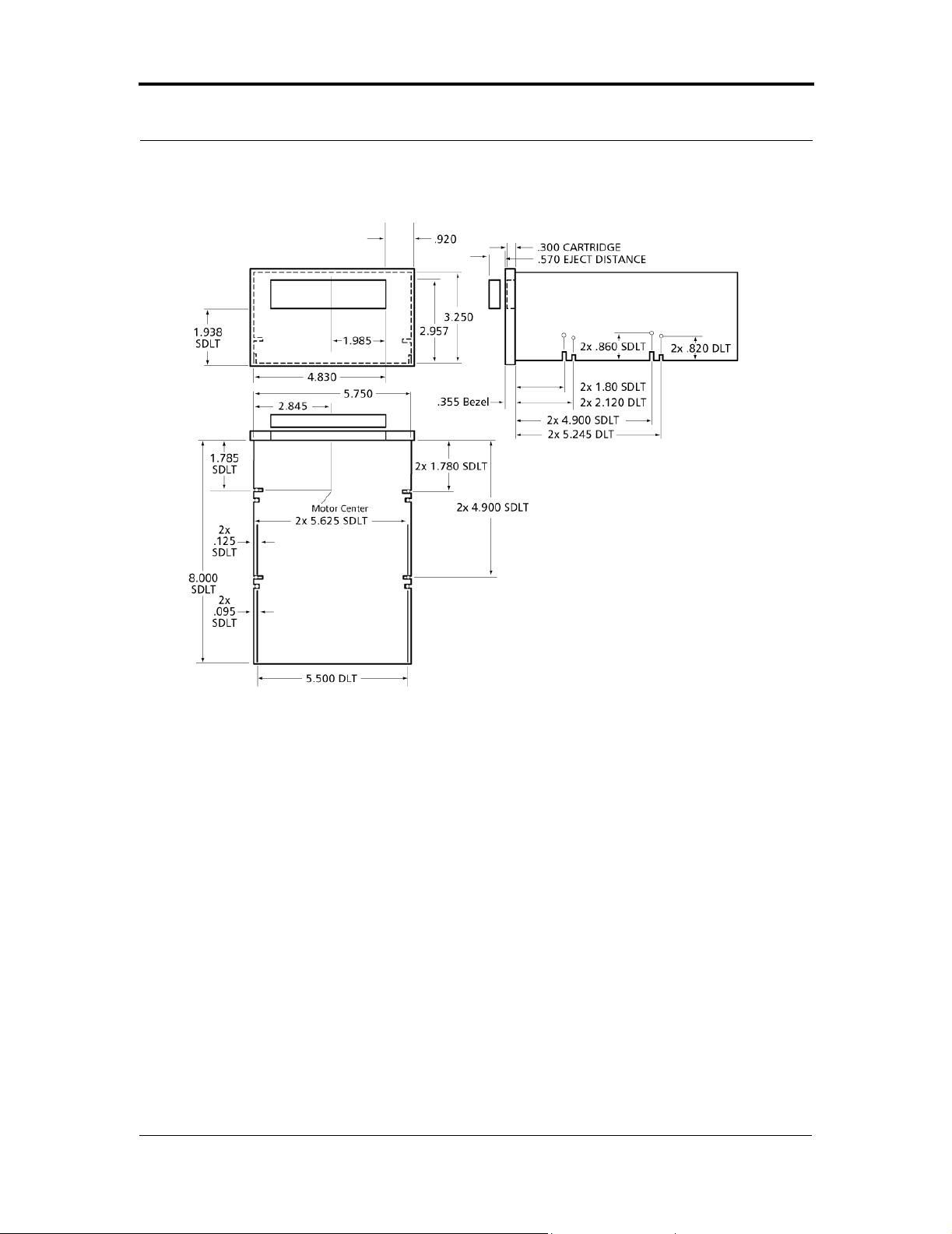
SDLT 220 and SDLT 320 Product Manual CHAPTER 4: Installing Your Tape Drive
2. Using four #6-32 UNC-2B screws, secure the tape drive in the bay or chassis.
Figure 4-5. Internal Drive Mounting Locations – Side and Bottom Views
Connecting the Internal Drive Cables
The three connectors on the back of the internal SDLT drive that are discussed in
this section are: 1) SCSI, 2) power, and 3) optional library/loader connectors. For
the tabletop model, typical connectors (power cords) are shown in Figure 4-8 on
page 4-24.
SCSI and Power Connectors
Figure 4-6 on page 4-15 shows the pin orientation for the 68-pin SCSI connector
and 4-pin power connector located on the back of the internal tape drive.
81-85002-01 March 2004 4-13
Page 66

CHAPTER 4: Ins talling Your Tape Drive SDLT 220 and SDLT 320 Prod uc t Ma nu al
Pin assignments for the three possible SCSI connectors are listed in a series of
tables: Multimode Single-Ended (MSE) Single Ended (SE) mode in Table 4-3 on
page 4-15, MSE Low Voltage Differential (LVD) mode in Table 4-4 on page 4-17,
and High Voltage Differential (HVD) mode in Table 4-5 on page 4-18. Pin
assignments for the power connector are listed in Table 4-6 on page 4-20.
1. Prior to connecting the SDLT drive to the host computer, make sure the drive
and computer are turned OFF.
2. If you are connecting several devices to the SCSI bus, connect only the drive
to the host computer at this time. Conf irm that the host compute r and drive are
communicating correctly before adding additional devices.
3. The SCSI bus must be terminated at each end. This drive may need to be
terminated:
if the SDLT drive is the only device connected to the SCSI bus, OR
if the SDLT drive is one of several devices connected to the SCSI bus,
and it is the last device connected to the SCSI bus.
4. If the answer to step 3 was affirmative, attach a “Y” connector to the drive’s
SCSI connector; then attach the SCSI cable to one leg of the “Y” and attach
the terminator to the other leg. Carefully connect the cables, to avoid bending
or damaging the connector pins.
5. Attach the power cables to the drive. Check the SCSI cable and termination
connections and ensure that they are attached correctly and seated firmly.
NOTE: The “Y” connector is not provided by Quantum.
Optional Loader Connector
The 8-pin optional loader connector provides signals to be used when the tape
drive is part of a loader/library configuration. Figure 4-6 on page 4-15 shows the
location of this connector; pin assignments for the loader connector are listed in
Table 4-7 on page 4-20.
4-14 March 20 04 81-850 02 - 01
Page 67

SDLT 220 and SDLT 320 Product Manual CHAPTER 4: Installing Your Tape Drive
Figure 4-6. Connectors on the Back Panel (Dra wn to Scale)
Table 4-3 . MSE and SE Mode SCSI Connector Pin Assignments
Signal Name Pin Number Pin Number Signal Name
Ground 1 35 -DB(12)
Ground 2 36 -DB(13)
Ground 3 37 -DB(14)
Ground 4 38 -DB(15)
Ground 5 39 -DB(P1)
Ground 6 40 -DB(0)
Ground 7 41 -DB(1)
Ground 8 42 -DB(2)
Ground 9 43 -DB(3)
Ground 10 44 -DB(4)
Ground 11 45 -DB(5)
Ground 12 46 -DB(6)
Ground 13 47 -DB(7)
Ground 14 48 -DB(P0)
Ground 15 49 Ground
81-85002-01 March 2004 4-15
Page 68

CHAPTER 4: Ins talling Your Tape Drive SDLT 220 and SDLT 320 Prod uc t Ma nu al
Table 4-3 . MSE and SE Mode SCSI Connector Pin Assignments (Continued)
DIFFSENS 16 50 Ground
TERMPWR 17 51 TERMPWR
TERMPWR 18 52 TERMPWR
Reserved 19 53 Reserved
Ground 20 54 Ground
Ground 21 55 -ATN
Ground 22 56 Ground
Ground 23 57 -BSY
Ground 24 58 -ACK
Ground 25 59 -RST
Ground 26 60 -MSG
Ground 27 61 -SEL
Ground 28 62 -C/D
Ground 29 63 -REQ
Ground 30 64 -I/O
Ground 31 65 -DB(8)
Ground 32 66 -DB(9)
Ground 33 67 -DB(10)
Ground 34 68 -DB(11)
Note: The min us sign (-) next to a signal indicates active low.
4-16 March 20 04 81-850 02 - 01
Page 69

SDLT 220 and SDLT 320 Product Manual CHAPTER 4: Installing Your Tape Drive
Table 4-4 . MSE LVD Mode SCSI Connector Pin Assignments
Signal Name Pin Number Pin Number Signal Name
+DB(12) 1 35 -DB(12)
+DB(13) 2 36 -DB(13)
+DB(14) 3 37 -DB(14)
+DB(15) 4 38 -DB(15)
+DB(P1) 5 39 -DB(P1)
+DB(0) 6 40 -DB(0)
+DB(1) 7 41 -DB(1)
+DB(2) 8 42 -DB(2)
+DB(3) 9 43 -DB(3)
+DB(4) 10 44 -DB(4)
+DB(5) 11 45 -DB(5)
+DB(6) 12 46 -DB(6)
+DB(7) 13 47 -DB(7)
+DB(P) 14 48 -DB(P)
Ground 15 49 Ground
DIFFSENS 16 50 Ground
TERMPWR 17 51 TERMPWR
TERMPWR 18 52 TERMPWR
Reserved 19 53 Reserved
Ground 20 54 Ground
+AT N 21 55 -ATN
Ground 22 56 Ground
+BSY 23 57 -BSY
+ACK 24 58 -ACK
+RST 25 59 -RST
+MSG 26 60 -MSG
+SEL 27 61 -SEL
+C/D 28 62 -C/D
+REQ 29 63 -REQ
+I/O 30 64 -I/O
81-85002-01 March 2004 4-17
Page 70

CHAPTER 4: Ins talling Your Tape Drive SDLT 220 and SDLT 320 Prod uc t Ma nu al
Table 4-4 . MSE LVD Mode SCSI Connector Pin Assignments (Continued)
+DB(8) 31 65 -DB(8)
+DB(9) 32 66 -DB(9)
+DB(10) 33 67 -DB(10)
+DB(11) 34 68 -DB(11)
Table 4-5 . HVD Mode SCSI Connector Pin Assignments
Signal Name Pin Number Pin Number Signal Name
+DB(12) 1 35 -DB(12)
+DB(13) 2 36 -DB(13)
+DB(14) 3 37 -DB(14)
+DB(15) 4 38 -DB(15)
+DB(P1) 5 39 -DB(P1)
Ground 6 40 Ground
+DB(0) 7 41 -DB(0)
+DB(1) 8 42 -DB(1)
+DB(2) 9 43 -DB(2)
+DB(3) 10 44 -DB(3)
+DB(4) 11 45 -DB(4)
+DB(5) 12 46 -DB(5)
+DB(6) 13 47 -DB(6)
+DB(7) 14 48 -DB(7)
+DB(P) 15 49 -DB(P)
DIFFSENS 16 50 Ground
TERMPWR 17 51 TERMPWR
TERMPWR 18 52 TERMPWR
Reserved 19 53 Reserved
+AT N 20 54 -ATN
Ground 21 55 Ground
+BSY 22 56 -BSY
+ACK 23 57 -ACK
+RST 24 58 -RST
4-18 March 20 04 81-850 02 - 01
Page 71

SDLT 220 and SDLT 320 Product Manual CHAPTER 4: Installing Your Tape Drive
Table 4-5 . HVD Mode SCSI Connector Pin Assignments (Continued)
+MSG 25 59 -MSG
+SEL 26 60 -SEL
+C/D 27 61 -C/D
+REQ 28 62 -REQ
+I/O 29 63 -I/O
Ground 30 64 Ground
+DB(8) 31 65 -DB(8)
+DB(9) 32 66 -DB(9)
+DB(10) 33 67 -DB(10)
+DB(11) 34 68 -DB(11)
81-85002-01 March 2004 4-19
Page 72

CHAPTER 4: Ins talling Your Tape Drive SDLT 220 and SDLT 320 Prod uc t Ma nu al
Table 4-6 . 4-Pin Power Connector Pin Assignments
Pin Numb er Signal Name
1 +12 VDC
2 Ground (+12V return)
3 Ground (+5V return)
4 +5 VDC
Table 4-7 . 8-Pin Loader Connector Pin Assignments
Signal Name Pin Number Pin Number Signal Name
Ground 1 5 SEND_TO_LOADER_H
REC_FROM_LOADER_H 2 6 SEND_TO_LOADER_L
REC_FROM_LOADER_L 3 7 Ground
Ground 4 8 LOADER_PRESENT_L
4-20 March 20 04 81-850 02 - 01
Page 73
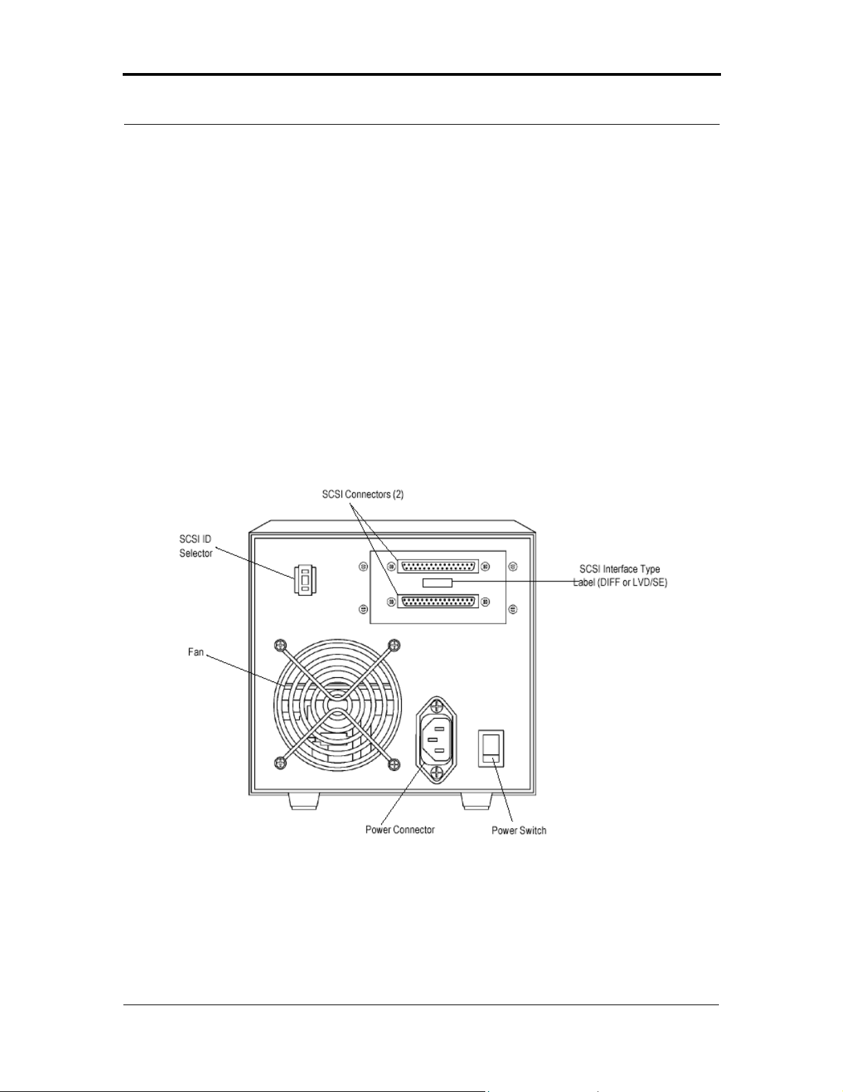
SDLT 220 and SDLT 320 Product Manual CHAPTER 4: Installing Your Tape Drive
4.4 Configuring and Inst alling a Tabletop Drive
This section provides instructions for configuring and installing the SDLT tabletop
drive.
4.4.1 Configuring the Drive
Figure 4-7 shows the location of the controls and connectors for the tabletop drive.
This model tape drive is normally configured to meet customer specifications
before leaving the factory, so should not require any internal configuration changes
on-site.
Figure 4-7. Back Panel of the Tabletop Model
SCSI ID The SCSI ID default for the tabletop drive is set to 3; the drive can be
configured for SCSI ID addresses that range from 0 to 15 using the SCSI ID
pushbutton. Press the button above or below the ID number display to set the
81-85002-01 March 2004 4-21
Page 74

CHAPTER 4: Ins talling Your Tape Drive SDLT 220 and SDLT 320 Prod uc t Ma nu al
desired SCSI ID. The top button increases the ID number, the bottom button
decreases the ID number.
TERMPWR The TERMPWR setting for the tabletop drive is preconfigured at
the factory according to specific customer requirements. TERMPWR is not
selectable on-site.
4.4.2 Ins ta lling t he Tabletop Dri ve
Tabletop drive installation consists of connecting SCSI bus and power cables.
Figure 4-7 on page 4-21 shows the location of the two SCSI bus connectors and
power connector on the back of the tabletop drive.
SCSI Cables
The SCSI bus cable leading f rom the host adapter can be connected to either of the
connectors. If the tape unit is the last device on the bus, then a terminator s hould be
installed on the open connector . If the bus continues from the tape dri ve to another
SCSI device, then install a SCSI bus cable between the open connector and the
next device on the bus.
1. Prior to connecting the SDLT drive to the host computer, make sure the drive
and computer are turned OFF.
2. If you are connecting several devices to the SCSI bus, connect only the drive
to the host computer at this time. Conf irm that the host compute r and drive are
communicating correctly before adding additional devices.
3. The SCSI bus must be terminated at each end. Depending on the terminator
supplied (Quantum 68-pin LVD/single-ended terminator with part number 1260308-01 or Quantum 68-pin HVD differential terminator with part number
12-41769-01); snap the wire cable clamps into place or tighten the screws to
secure the terminator.
If the SDLT drive is the only device connected to the SCSI bus, attach the
SCSI terminator to one of the connectors on the back of the drive.
4-22 March 20 04 81-850 02 - 01
Page 75

SDLT 220 and SDLT 320 Product Manual CHAPTER 4: Installing Your Tape Drive
If the SDLT drive is one of several devices connected to the SCSI bus,
and it is the last device connected to the SCSI bus, attach the SCSI
terminator to one of the connectors on the back of the drive.
4. Align the appropriate SCSI cable to its matching connector on the drive.
Carefully connect the cable, to avoid bending or damaging the connector pins.
Check the SCSI cable and termination connections and ensure that they are
attached correctly and seated firmly.
5. Snap the wire cable clamps into place to secure the cables.
AC Power Cable
An AC power cord is supplied with each tabletop unit. Carefully inspect the power
cord and ensure that the cord is the appropriate cord for your country or region
based on the criteria below.
W
ARNING: Do not attempt to modify or use a tabletop 100–115
VAC power cord for 220–240 VAC input power.
Modifying the power cord in any way can cause
personal injury and severe equipment damage.
The AC power cord used with the tabletop unit must meet the following criteria:
• The power cord should be a minimum of 18/3 AWG, 60°C, type SJT or SVT.
• UL and CSA certified cordage rated for use at 250 VAC with a current rating
that is at least 125% of the current rating of the product.
• The AC plug must be terminated in a grounding-type male plug designed for
use in your country or region. It must also have marks showing certification
by an agency acceptable in your country or region.
• The tabletop unit cord connector must be an IEC type CEE-22 female
connector.
• The cord must be no longer than 4.5 meters (14.5 feet).
• The cord must be FCC compliant with emissions specifications.
Figure 4-8 on page 4-24 shows the AC power cord plug-end types for 115 VAC
and 220/240 VAC usage.
81-85002-01 March 2004 4-23
Page 76

CHAPTER 4: Ins talling Your Tape Drive SDLT 220 and SDLT 320 Prod uc t Ma nu al
Figure 4-8. AC Power Cord Connector Types
The power supply of the tabletop unit has an auto-sensing feature; no adjustment
or switch setting changes are required for different AC sources.
Refer to Figure 4-7 and Figure 4-8. Connect one end of the AC cord into the power
connector on the back of the tabletop drive; connect the other end of the cord to the
AC outlet. Upon completion, proceed to the next section to confirm the
installation.
4.5 Confirming the Installation
T o confirm the installation, power on the SDLT system and the host computer. The
screens displayed at power-up contain BIOS, operating system, and SCSI
controller information. If the first screen displays host adapter and SCSI ID
information, then the system is being recognized and the installation is successful.
Refer to “Tr oubleshooting” on page 5-17 if the installation is not successful.
4-24 March 20 04 81-850 02 - 01
Page 77

CHAPTER 5 Using You r Ta pe Drive
This chapter describes how to start using your tape drive system. This includes
making a trial back-up, cleaning the tape mechanism, and various troubleshooting
information. This chapter also includes information on the LEDs and buttons on
the front panel of the system.
This chapter covers the following topics:
• “Power On Self Test” describes the sequence of activities that occur when
power is first applied to the drive.
• “Performing a Trial Back-up” describes how to backup a sample f ile to ensure
proper operation of the system.
• “Updating the Firmware” describes how to update the firmware (microcode)
that resides inside the tape drive and controls its behavior.
• “Cleaning the Tape Mechanism” describes the considerations to keep in mind
when using SDLT cleaning cartridges.
• “Front Panel Controls and LEDs” describes the functionality of the front
panel controls and LEDs.
• “Density Selection” describes how to write to (or read from) data cartridges
using specific formats of your choice.
• “Troubleshooting” lists troubleshooting tips and diagnostic tools in the event
that the tape system fails.
81-8500 2 - 01 March 20 04 5-1
Page 78

CHAPTER 5: U si ng Your Tape D ri ve SDLT 220 and SDLT 320 Prod uc t Ma nual
5.1 Power On Self Test
When power is applied to the tape system, the system performs a Power On Self
Test (POST). POST completes in approximately ten seconds. While POST is
running, the tape system responds BUSY to SCSI commands. The tape system
also responds to various SCSI messages during POST.
During this time, if a host tries to negotiate Synchronous or Wide transfers, the
tape system will negotiate to Asynchronous or Narrow . It may take longer than the
duration of POST for the drive to become ready.
Table 5-1 . Indicator Pattern During POST
Stage What Can Be Observed
1 The LEDs light in a progressing pattern from left to right.
2 The red and yellow LEDs are extinguished and the green L ED
flashes until PO S T completes.
3 If POST fails, th e green and yellow LED will illuminate
steadily and the red LED will blink.
5-2 March 20 04 81-850 02-01
Page 79

SDLT 220 and SDLT 320 Product Manual CHAPTER 5: Using Your Tape Drive
5.2 Performing a Trial Back-up
Complete the following steps to perform a trial back-up and verify the tape drive
has been correctly installed:
• Insert a cartridge. Push the cartridge completely into the system. The tape will
load automatically.
• Choose a sample file set from the host computer.
• Perform a back-up and then restore the file set. The system has been correctly
installed if the back-up is completely restored without any errors. If you
experience errors, doublecheck the drive’ s configuration and setup, using the
ideas provided in “Troubleshooting” on page 5-17. After you have exhausted
all troubleshooting alternatives, contact your service representative.
• Press the Eject button to unload the cartridge. If you are unsure which button
is the Eject button, refer to Figure 5-1 on page 5-11.
NOTE: Y ou can review specific instructions for loading a tape
cartridge in Appendix A, “Super DL Ttape I Data
Cartridge,” and Appendix B, “DLTtape IV Data
Cartridge.”
81-85002-01 March 2004 5-3
Page 80

CHAPTER 5: U si ng Your Tape D ri ve SDLT 220 and SDLT 320 Prod uc t Ma nual
5.3 Updating the Firmware
When you need to update the firmware in a drive, you can do it either of t wo ways:
• Build a firmware image tape; this tape can be used in either a manual
firmware update or in a Library setting.
• Update the firmware over the SCSI bus.
Both of these approaches are described briefly in the following subsections.
NOTE: For more information about the suite of diagnostics tools
provided by Quantum, refer to Quantum’s web site,
http://www.quantum.com. Follow the path Support =>
Drivers and Software .
5.3.1 U pda te the Fir m w ar e U sing t h e SCSI Bus
SDLT Update is a tool that allows you to update a drive’s firmware (using the
SCSI bus), or to create a code update (CUP/FUP) tape for an SDL T drive.
SDLT Update is available on Quantum’s web site, http://www.quantum.com.
Follow the path Support =>Drivers and Software and download the SDLT
Update package. For detailed instructions to use while updating the firmware,
refer to that tool’s built-in online help.
5-4 March 20 04 81-850 02-01
Page 81

SDLT 220 and SDLT 320 Product Manual CHAPTER 5: Using Your Tape Drive
5.3.2 Making a FUP/CUP Tape
SDLT Update is a tool that allows you to update a drive’s firmware (using the
SCSI bus), or to create a code update (CUP/FUP) tape for an SDL T drive.
SDLT Update is available on Quantum’s web site, http://www.quantum.com.
Follow the path Support =>Drivers and Software and download the SDLT
Update package. For detailed instructions about how to make the tape, refer to that
tool’s built-in online help.
5.3.3 U sing a C UP/FUP Tape
Follow these steps to use a CUP/FUP tape that was previously created by you or
someone else:
1. Verify that the drive is turned on (power is applied), and the Green (Drive
Status) LED is on, but not blinking.
2. Verify that the drive’s tape opening is empty . (In other words, if any other tape
cartridge is in the drive, unload and eject it.)
3. Press and hold the Eject button for six seconds; after six seconds, the Amber
(Write Protect) LE D will begin to blink.
4. Release the Eject button, then quickly press and release the Eject button again.
At this point, the Amber and Green LEDs start blinking synchronously in a
regular, rhythmic pattern. The drive is now in Firmware Upgrade mode.
You now have a “window” of one minute to insert the tape cartridge. If you do
not insert a CUP/FUP tape and the one minute time window expires, both
LEDs will stop blinking, although the Green LED will remain on (steadily
illuminated). The drive is now out of Firmware Upgrade mode and can be
used in a normal manner (once you insert a data tape cartridge). To put the
drive back in Firmware Upgrade mode, repeat steps 2, 3, and 4 above.
5. Insert the CUP/FUP tape that was previously created.
6. After you insert the tape, the Amber LED and the Green LED will change
their pattern, and start blinking in an alternating pattern. The drive is now
performing the Firmware Upgrade.
81-85002-01 March 2004 5-5
Page 82

CHAPTER 5: U si ng Your Tape D ri ve SDLT 220 and SDLT 320 Prod uc t Ma nual
NOTE: The Firmware Upgrade will fail the microcode update
process if the firmware personalities do not match; this
will be noted in the history log, along with the reason for
the failure.
7. Wait several minutes for the update process to complete. The Amber and
Green LEDs will blink the entire time that memory is being updated.
8. When the update is complete, the drive resets itself and goes through POST.
The tape is rewound, unloaded, and ejected from the drive. SCSI status will
indicate that microcode has been updated (06h, 3F, 01).
NOTE: If the drive is mounted in a tape automation library, the
tape is not automatically ejected, but it is rewound to
BOT and unbuckled in preparation for unloading.
5.3.4 Troubleshooting th e Firmwa re (Code ) Up dat e
Try these remedial actions if the drive’s firmware (code) update fails:
• Updating the same revision
If a Code Update is requested and the code revision being updated is the same
as the code revision already in the unit, the system updates controller code but
not servo-specific code. The steps for this type of update are the same as for a
normal update.
• Updating fails, which causes the drive to be reset; the problem can result from
any of the following circumstances:
Cartridge contains incompatible update image.
Cartridge does not contain an update image.
No cartridge in the drive.
5-6 March 20 04 81-850 02-01
Page 83

SDLT 220 and SDLT 320 Product Manual CHAPTER 5: Using Your Tape Drive
5.4 Cleaning the Tape Mechanism
This section discusses the SDL T cleaning tape, maintenance considerations, and
important compatibility issues you need to be aware of.
NOTE: Use the SDLT cleaning tape if cleaning is indicated
through your backup software or when the yellow alert
light is ON. Do not clean the drive unless the drive
specifically indicates cleani ng is necess ar y.
5.4.1 O cca si onal Cleaning of Tape Head
SDLT drives may not require preventative cleaning, because of improvements in
the head design. The frequency of cleaning is dictated, to a large degree, by the
amount of ambient pollution and particulates in the environment. For details , refer
to “Particulate Contamination Limits” on page 3-15.
Do not clean your drive unless cleaning is indicated. Your backup software or the
yellow alert light (LED) notify you if you need to clean the drive.
CAUTION: Never use a DLT cleaning tape in an SDL T drive; DLT
cleaning tapes are incompatible wit h the SDLT heads.
81-85002-01 March 2004 5-7
Page 84

CHAPTER 5: U si ng Your Tape D ri ve SDLT 220 and SDLT 320 Prod uc t Ma nual
5.4.2 When to Use the Cleaning Tape
SDLT uses a built-in tape cleaning algorithm in conjunction with a cleaning tape.
The SDLT cleaning tape is housed in a plastic case, and is light gray in color.
A yellow LED (light) located on the front bezel of the tape drive indicates when
cleaning is needed; the location of this LED (and other front bezel LEDs) is shown
in Figure 5-1 on page 5-11.
NOTE: The tape cleaning algorithm is not used for the backward
read compatible (BRC) head; this head style does not need
cleaning.
5.4.3 Life Expectancy o f the C leaning Tape
Each SDLT cleaning tape is good for 20 uses. Use one of the Quantum-supplied
labels that come with the tape to keep track of the number of uses.
5.4.4 Compatibility of the Cleaning Tape
The SDLT cleaning tape is intended for use in SDLT drives, autoloaders and
libraries only. Alternatively stated, the cleaning t ape only cleans the SDLT MRC
heads.
AUTION: Never use a DLT cleaning tape in an SDL T drive; DLT
C
cleaning tapes are incompatible wit h the SDLT heads.
5-8 March 20 04 81-850 02-01
Page 85

SDLT 220 and SDLT 320 Product Manual CHAPTER 5: Using Your Tape Drive
5.4 . 5 Lo ading the Clean ing Tape Into a T abletop Drive
NOTE: To use the cleaning cartridge in an Autoloader or Library
drive, refer to your owner’s manual.
Follow these steps to load an SDLT cleaning tape into an SDLT tabletop drive:
1. Insert the cleaning cartridge, with the Front Slide Label Slot facing outward,
into the drive until the drive engages with the cartridge and begins to take up
the cleaning media. The green Drive Status LED blinks and the cleaning cycle
begins automatically.
2. When the cleaning cycle completes, the cartridge automatically ejects from
the drive and the yellow alert LED turns off.
NOTE: On the last cleaning, the cleaning cartridge wi ll not eject.
Use the Eject button on the front of the drive to eject the
expired cleaning cartridge and dispose of the cartridge.
3. Remove the cartridge, place it back into its plastic case, and mark the label
after each cleaning.
81-85002-01 March 2004 5-9
Page 86

CHAPTER 5: U si ng Your Tape D ri ve SDLT 220 and SDLT 320 Prod uc t Ma nual
5.5 Front Panel Controls and LEDs
All controls and LEDs are located on the tape drive’s front panel. See Figure 5-1
on page 5-11 for details. Control and LED functionality a re de scri bed i n Table 5-2
and Table 5-3. Use these controls and LEDs to operate the tape system and monitor
the tape system’ s activities.
This section also describes the behavior of the amber-colored LED (formerly Write
Protect) on the SDLT 320 drive. This LED is now defined as the Density Indicator,
as shown in Table 5-2.
Table 5-2 . Behavior of the Amber LED When a Tape Cartridge is Loaded
Cartridge Type SDLT 220 SDLT 320*
DLTtape IV [includes DLT 1
(Benchmark)]
Super DLTtape I LED is not illuminated LED is illuminated for oth er
* Firmware revision V45 or higher.
‡ Amber LED is used as a Density Indicator on SDLT 320.
LED is il lu minat e d LE D is not illu mina te d
reasons
‡
5-10 March 20 04 81-850 02 - 01
Page 87
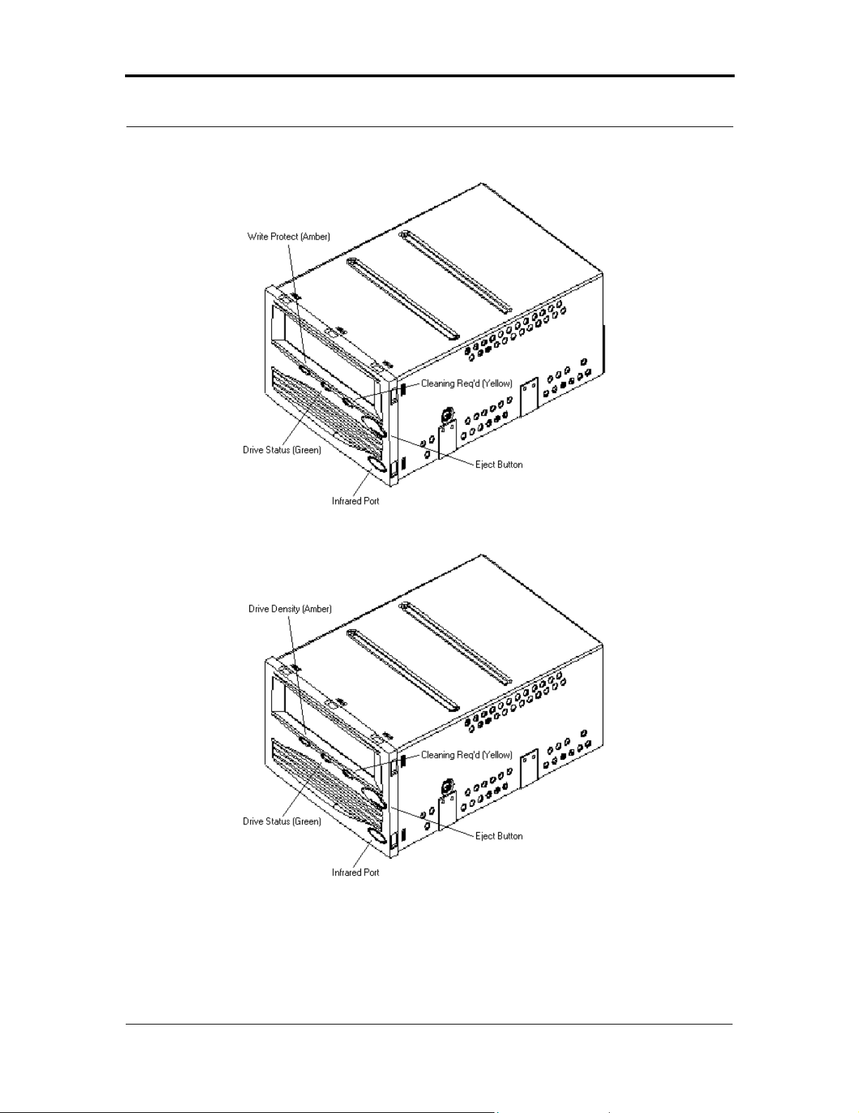
SDLT 220 and SDLT 320 Product Manual CHAPTER 5: Using Your Tape Drive
SDL T 220
SDL T 320
Figure 5-1. SDLT 220 and SDLT 320 Front Panels (A Comparison)
81-85002-01 March 2004 5-11
Page 88
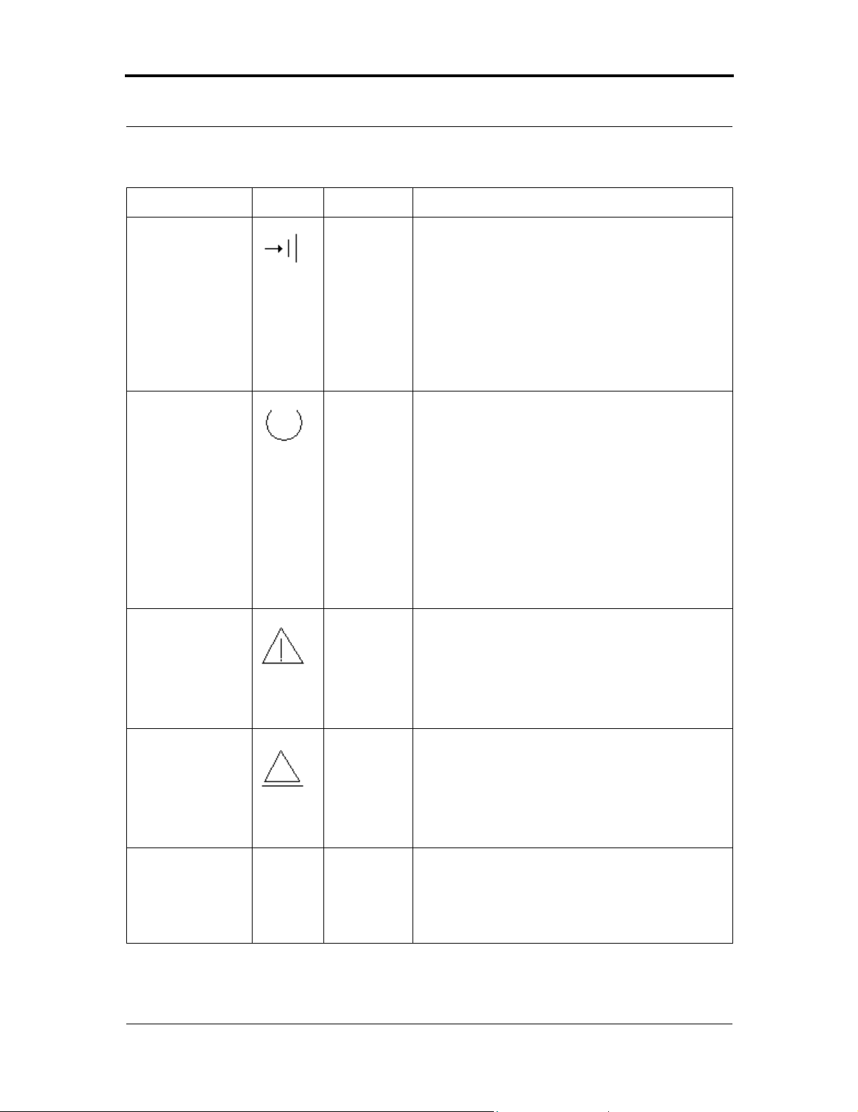
CHAPTER 5: U si ng Your Tape D ri ve SDLT 220 and SDLT 320 Prod uc t Ma nual
Table 5-3 . Front Panel LED/Control Functionality
LED/Button Symbol LED Color Description
Write P rotect L E D
(Left on SDLT 220)
OR
Drive Density LED
(Left on SDLT 320)
Drive Status LED
(Center)
Cleaning Required
LED (Right)
220
Amber For the SDLT 320 drive, th is LED functions as the
“Drive Density Indicator” LED; for the SDLT 220
drive, this LED is the “Write Protect” LED.
On =
220: The tape is write-protected
320: The tape is 220-formatted
Off =
220: The tape is write-enabled
320: The tape is 320-formatted
Green Blinking = The drive is in use; this includes functions
such as:
• The tape is moving
• The drive is calibrating, reading, writing, or
rewinding the tape
• The tape is loading, unloading or rewinding.
On = The drive is idle. There may or may not be a
cartridge in the tape drive.
Off = The tape drive has not been turned on or is not
plugged into a power sou r ce .
Yellow On = Cleaning required. See “Cleani n g th e Tape
Mechanism” on page 5-7.
Off = Cleaning is not required.
Eject Button Use the Eject button to eject the tape cartridge from the
drive. When you press the button, the drive completes
any active writing of data to the tape, then ejects the
cartridge.
Refer to the applicabl e ta pe cartridge appendix for
detailed tape cartridge handling procedures.
Infrared
Communication
Port
5-12 March 20 04 81-850 02 - 01
This infrared port, also known as the Global Storage
Link (GS Link), provides a wireless remote testing
base for custome rs and integ rat or s to access syst em
diagnostic in form ation. See your Quantum sales
representative for more information.
Page 89

SDLT 220 and SDLT 320 Product Manual CHAPTER 5: Using Your Tape Drive
5.6 Density Selection
This section describes the SDLT drive’s density select features. Density selection
is a feature that enables you to specify that your SDLT 320 tape drive write data
cartridges that are backward compatible with your SDL T 220 tape drives. For
example, if you load a new Super DLTtape I data cartridge in the tape drive and
use a commercially available backup utility , your SDLT 320 tape drive writes data
in SDLT 320 format. However, by using Density Select to specify SDLT 220
format, the SDLT 320 tape drive reads and writes data in that format, enabling
SDLT 220 tape drives to read the data cartridge.
5.6.1 Selecting Tape Density
Selecting Density via the Host over the SCSI Bus
1. Use the SCSI MODE SELECT command to indicate the desired density.
NOTE: Any of the following events cause the drive to reve rt to its
default density: loading a new data cartridge, power on
reset, bus reset, and bus device reset.
2. Write data to the tape from BOT.
When writing from BOT , tape density may be changed by using the operating
system to issue a density designation, or override. In this case, the amber Drive
Density LED on the tape drive’s front panel behaves as shown in Table 5-4 on
page 5-16, indicating an automatic or host density selection.
NOTE: On all READ and all WRITE APPEND operations, the
data density that already exists on the tape cartridge
remains the density.
81-85002-01 March 2004 5-13
Page 90

CHAPTER 5: U si ng Your Tape D ri ve SDLT 220 and SDLT 320 Prod uc t Ma nual
CAUTION: If a prerecorded tape is reused and a WRITE from the beginning of tape
(BOT) executes (No Append Write), any data already recorded on the tape
will be lost.
SDLT 220 and S DLT 320 C ompatibility Issues
For more information about what happens when a 320-formatted cartridge is
inserted into a SDLT 220 drive, refer to Section A.7, “Overwriting 320-Formatted
Super DLTtape I Data Cartridges” on page A-11.
Forcing Tape Density with MODE SELECT Parameters
The Default Density Override parameter on the Vendor Specific Configuration
Page (25h) can be used to override the default density for the tape until a new data
cartridge is loaded.
NOTE: For more specific information about tape density codes,
refer to the SCSI command descriptions for MODE
SELECT and MODE SENSE. You can find these in a
separate document published by Quantum, SDLT 220 and
SDLT 320 SCSI Interface Guide, 81-85001-01.
5-14 March 20 04 81-850 02 - 01
Page 91

SDLT 220 and SDLT 320 Product Manual CHAPTER 5: Using Your Tape Drive
5.6.2 Tape Density and t he D r ive D ensity Indicat or
This section describes the behavior of the left-most LED on the Quantum SDLT
320 data tape drive. This amber-colored LED is now defined as the Drive Density
indicator (formerly Write Protect).
On the SDLT 320 drive only (not SDLT 220), the amber LED is illuminated when
the density has been set to 220 mode or when an inserted cartridge is detected by
the drive as being formatted in 220 mode. This LED is not illuminated when the
drive is operating in 320 mode, which is the default. See Table 5-4 for specific
scenarios.
Refer to T able 5-4 to help you interpret the behavior of the Drive Density Indicator
LED. Also, please note that the Drive Density LED is not illuminated while the
drive is reading DLT BRC cartridges (DLTtape 4000, 7000, 8000, and DLT1).
81-85002-01 March 2004 5-15
Page 92

CHAPTER 5: U si ng Your Tape D ri ve SDLT 220 and SDLT 320 Prod uc t Ma nual
Table 5-4 . Behavior of the Amber (Drive Density) LED in Various Scenarios
Possible Tape
Scenario
No Tape Inserted OFF 49h ON 48h OFF 49h
Blank Tape Inserted OFF 49h ON 48h OFF 49h
220 Formatted Tape at
BOT
220 Formatted Tape
Reading or Appending
220 Formatted Tape
Write Protected
220 Formatted Tape at
BOT and Received
Write Command
320 Formatted Tape at
BOT
No Selected
Density Mode
Density
LED
ON 48h ON 48h BLINK 48h
ON 48h ON 48h BLINK 48h
ON 48h ON 48h ON 48h
ON 48h ON 48h OFF * 49h*
OFF 49h BLINK 49h OFF 49h
Code LED
Host Selected
SDLT 220 Mode
Density
Code LED
Host Selected
SDLT 320 Mode
Density
Code
320 Formatted Tape
Reading or Appending
320 Formatted Tape
Write Protected
320 Formatted Tape at
BOT and Received
Write Command
DLT Type IV Tape
(BRC)
* Converts tape to 320 format before processing the write command.
** Converts tape to 220 form at before processing the write co mmand.
† Returns proper DLT density code based on format (DLTtape 4000, 7000, 8000, or DLT1).
5-16 March 20 04 81-850 02 - 01
OFF 49h BLINK 49h OFF 49h
OFF 49h OFF 49h OFF 49h
OFF 49h ON** 48h** OFF 49h
OFF
DLT
†
OFF
DLT
†
OFF
DLT
†
Page 93

SDLT 220 and SDLT 320 Product Manual CHAPTER 5: Using Your Tape Drive
5.7 Troubleshooting
The following subsections provide troubleshooting information that might be
helpful should the system fail its Power-On Self Text (POST).
Refer to the tape cartridge appendices in this manual (Appendix A, “Super
DLTtape I Data Cartridge” and Appendix B, “DLTtape IV Data Cartridge” ) fo r
complete visual inspection instructions for Super DLTtape I and DL Ttape data
cartridges.
The web site http://www.quantum.com/sdlt includes much valuable information
about SDLT systems.
5.7.1 POST Troubleshooting
Table 5-5 provides troubleshooting tips that you will find useful in the event that
your tape system fails its POST.
If, after attempting the recommended actions listed in the table, the problem still
exists or recurs, a hardware failure may be the cause. Contact your service
representative.
Table 5-5 . Troubleshooting Chart
If… T he n… Yo u s houl d …
System does not
recognize the tape
system.
System may not be configured to
recognize the SCSI ID.
SCSI ID may not be unique. Change the SCSI ID and reconfigure the
SCSI adapter parameters may not be
correct.
SCSI signal cable may be loose. Ensure SCSI cable is fully seated at each
SCSI terminator may be loos e or not
present on the bus.
Configure system to recognize the tape
system’s ID.
system. The new ID becomes effective at
the next power on or SCSI bus reset.
Check SCSI adapter docum entation.
connector end.
Ensure correct, secure termination of bus.
81-85002-01 March 2004 5-17
Page 94

CHAPTER 5: U si ng Your Tape D ri ve SDLT 220 and SDLT 320 Prod uc t Ma nual
Table 5-5 . Troubleshooting Chart (Continued)
System does not
recognize the tape
system. (cont.)
SCSI bus may not be terminated
correctly.
If tape system is las t or only device on
bus (except for adapter), make sure
terminator is installed on tape system.
If tape system is not the la st or only
device on the bus, ch ec k the cable
connections and ensure that the bus is
properly terminated at ea ch en d.
SCSI terminator may not be at end
of bus or more than two terminators
may be present.
Ensur e that a terminator is insta ll ed at
each end of the bus. One terminator is
usually installed at the host end of the
bus.
SCSI bus may be too long. Limit bus length to ANSI SCSI standard
for the SCSI interface being used.
Too m any devices on the bus. Limit the number of devices on the bus
(including the SCSI adapter) to match the
limits of the interface being used.
A device may not have been turned
on and a valid SCSI ID may not
have been configured prior to the
system powering on and loading
Turn drive power on firs t, and then turn
on power to the system. Do this so that
the drive is properly recognized by the
system.
BIOS.
The tape system does
not power up.
Nonfatal or fatal errors
have occurred for
which the cause
cannot be determined.
No power is reaching the tape
system.
SCSI bus termination or the SCSI
bus cable connections ma y be
incorrect.
The AC power source grounding
may be incorrect (tabletop version).
Check the tape system’s power cable
connection at the back of the system.
Ensure the S CSI bus is terminated and
that all connections are secure. Use an
AC outlet for the ta bletop t ape unit on the
same AC line used by the host s ystem.
5-18 March 20 04 81-850 02 - 01
Page 95

SDLT 220 and SDLT 320 Product Manual CHAPTER 5: Using Your Tape Drive
5.7.2 O ver Temperatur e C ondition
An Overtemp condition is defined to be when the calculated Tape Path Temp =
52 degrees C. When this condition is detected, the tape is rewound, unloaded, and
ejected from the drive. (As long as the drive is not mounted in a tape automation
library, the tape is ejected.) SCSI status will indicate the drive is in the over
temperature condition.
NOTE: If the drive is mounted in a tape automation library, the
tape is not automatically ejected; for details , refe r to a
separate document, SDLT 220 and SDLT 320 Design and
Integration Guide, 81-81148-01.
81-85002-01 March 2004 5-19
Page 96

CHAPTER 5: U si ng Your Tape D ri ve SDLT 220 and SDLT 320 Prod uc t Ma nual
5-20 March 20 04 81-850 02 - 01
Page 97

CHAPTER 6 SCSI Description
This chapter covers the following topics:
• “SCSI Overview” introduces the SCSI specification.
• “SCSI-2 Commands” lists the SCSI-2 commands implemente d by
SDLT 220/320.
• “SCSI-3 Commands” lists the SCSI-3 commands implemente d by
SDLT 220/320.
• “Parity” defines the meaning of data parity checking.
• “Signal States” defines the meaning of SCSI signal values and SCSI IDs.
• “SCSI Signals” defines SCSI signals and provides bus timing values.
6.1 SCSI Overview
The Small Computer System Interface (SCSI) is a specification for a peripheral
bus and command set that is an ANSI standard. The standard defines an I/O wide
SCSI bus that supports up to 16 devices (15 SCSI devices and one host adapter).
ANSI defines three primary objectives for SCSI-2:
1. T o provide host computers with device-independence within a class of
devices.
2. To be backward-compatible with SCSI-1 devices that support bus parity and
that meet conformance level 2 of SCSI-1.
3. To move device-dependent intelligence to the SCSI-2 devices.
81-8500 2 - 01 March 20 04 6-1
Page 98

CHAPTER 6: SCSI Description SDLT 220 and SDLT 320 Product Manual
Important features of SCSI-2 implementation include the following:
• Efficient peer-to-peer I/O bus with up to 15 devices
• Asynchronous transfer rates that depend only on device implementation and
cable length
• Logical addressing for all data blocks (rather than physical addressing)
• Multiple initiators and multiple targets
• Distributed arbitration (bus contention logic)
• Command set enhancement.
For more details about specific SCSI commands or messages, refer to a separate
document published by Quantum, SDLT 220 and 320 SCSI Interface Guide,
81-85001-01.
6-2 March 20 04 81-850 02-01
Page 99

SDLT 220 and SDLT 320 Product Manual CHAPTER 6: SCSI Description
6.2 SCSI-2 Commands
ANSI classifies SCSI commands as mandatory, optional, or vendor-specific.
The mandatory and optional SCSI-2 commands implemented for the drives are
summarized in Table 6-1.
Table 6-1 . Implemented ANSI SCSI-2 Commands
Command Cod e Class Description
ERASE 19h Mandatory Causes part or all of the tape medium to be
erased, beginni ng at the current position on th e
logical unit.
INQUIRY 12h Mandatory Requests that information be sent to the initiator.
LOAD UNLOAD 1Bh Optional Causes tape to move from not ready to ready.
Prior to performing the load unload, the target
ensures that all data, filemarks, and/ or setmarks
shall have transf erred to the tape medium.
LOCATE 2Bh Optional Causes the target to position the lo gical unit to
the spec ified block address in a sp ecified
partition. When complete, the logical position is
before the specified position.
LOG SELECT 4Ch Optional Provides a means for the ini tiator to manage
statistical in f o r m a ti o n m a in tained by th e d ri v e
about the drive. This standard defines the format
of the log pages but does no t define the exact
conditions a nd events that are logged.
LOG SENSE 4Dh Optional Provides a means for the initiator to retrieve
statistical in f o r m a ti o n m a in tained by th e d ri v e
about th e d rive.
MODE SELECT (6)/(10) 15h/
55h
MODE SENSE (6)/(10) 1Ah/
5Ah
PREVENT ALLOW
MEDIUM REMOVAL
READ 08h Mandatory Requests the drive to transfer data to the initiator.
1Eh Optional Requests that the target enable or disable the
Optional Provides a means for the initiator to specify
device parameters.
Optional Provides a means for a dri ve to r eport pa ramete rs
to the in it iator.
removal of th e medium in the logica l unit.
Medium cannot be removed if any initiator has
medium removal prevente d.
READ BLOCK LIMITS 05h Mandatory Requests that the logical unit’s block length
limits ca pability be returned.
81-85002-01 March 2004 6-3
Page 100

CHAPTER 6: SCSI Description SDLT 220 and SDLT 320 Product Manual
Table 6-1 . Implemented ANSI SCSI-2 Commands (Continued)
Command Cod e Class Description
READ BUFFER 3Ch Optional Used in conjunction with the WRITE BUFFER
command as a diagnostic function for testing
target m em ory and the integrity of the SCSI bus.
This command does not alt er the medium.
READ POSITION 34h Optional Reports the current position of the logical unit
and any data blocks in the buffer.
RECEIVE DIAG
RESULTS
1Ch Optional Requests analysis data to be sent to the initiator
after completion of a SEND DIAGNOSTIC
command.
RELEASE UNIT 17h Mandatory Used to release a previous ly reserved logical
unit.
REQUEST SENSE 03h Mandatory Requests the drive to transfer sense data to the
initiator.
RESERVE UNIT 16h Mandat ory Used to reserve a logical unit.
SEND DIAGNOSTIC 1Dh Mandatory Requests the drive to perform diagnostic
operations on its elf.
SPACE 11h Mandatory Provides a selection of positioning functions
(both forward a nd b ackward) t hat a re det ermined
by the code and count.
TEST UNIT READY 00h Mandatory Pr ovides a means to check if the logi ca l unit is
ready.
VERIFY 2Fh Optional Requests the drive to ve rify the data written to
the medium.
WRITE 0Ah Mandatory Requests the drive to write data transferred from
the initiator to the medium.
WRITE BUFFER 3Bh Optional Used in conjunction with the READ BUFFER
command as a diagnostic for testing target
memory and the integrity of the SCSI bus.
WRITE FILEMARKS 10h Mandatory Requests that the target write the specified
number of filemarks or setmarks to the current
position on the logical unit.
6-4 March 20 04 81-850 02-01
 Loading...