

Page 1

®
Scalar
Distributed Library Controller
Installation Guide
™
2.7
Page 2

Scalar Distributor Library Controller Reference Guide, 6-00659-04, September 2007, Made in USA.
Quantum Corporation provides this publication “as is” without warranty of any kind, either express or implied, including
but not limited to the implied warranties of merchantability or fitness for a particular purpose. Quantum Corporation
may revise this publication from time to time without notice.
COPYRIGHT STATEMENT
Copyright 2007 by Quantum Corporation. All rights reserved.
Your right to copy this manual is limited by copyright law. Making copies or adaptations without prior written
authorization of Quantum Corporation is prohibited by law and constitutes a punishable violation of the law.
TRADEMARK STATEMENT
Quantum, DLT, DLTtape, ADIC, the Quantum logo, and the DLTtape logo are all registered trademarks of Quantum
Corporation.
SDLT and Super DLTtape are trademarks of Quantum Corporation.
Reference Guide
Published: September 2007 Document Number: 6-00659-04 Rev. A
Page 3

Table of Contents
1 About This Guide and Your Product 1
Explanation of Symbols and Notes . . . . . . . . . . . . . . . . . . . . . . . . . . . . . . . . . . . . . . . . . . . . . . . . . . . . . 1
Other Documents You Might Need . . . . . . . . . . . . . . . . . . . . . . . . . . . . . . . . . . . . . . . . . . . . . . . . . . . . . 1
Getting More Information or Help . . . . . . . . . . . . . . . . . . . . . . . . . . . . . . . . . . . . . . . . . . . . . . . . . . . . . . 2
2 System Description 3
Platforms . . . . . . . . . . . . . . . . . . . . . . . . . . . . . . . . . . . . . . . . . . . . . . . . . . . . . . . . . . . . . . . . . . . . . . . . . 5
Solutions . . . . . . . . . . . . . . . . . . . . . . . . . . . . . . . . . . . . . . . . . . . . . . . . . . . . . . . . . . . . . . . . . . . . . . . . . 5
Standard Solution . . . . . . . . . . . . . . . . . . . . . . . . . . . . . . . . . . . . . . . . . . . . . . . . . . . . . . . . . . . . . . . 5
Failover Solution . . . . . . . . . . . . . . . . . . . . . . . . . . . . . . . . . . . . . . . . . . . . . . . . . . . . . . . . . . . . . . . . 6
Self-Domain Solution. . . . . . . . . . . . . . . . . . . . . . . . . . . . . . . . . . . . . . . . . . . . . . . . . . . . . . . . . . . . . 6
Compatibility Matrix. . . . . . . . . . . . . . . . . . . . . . . . . . . . . . . . . . . . . . . . . . . . . . . . . . . . . . . . . . . . . . . . . 7
3 Setting Up the Scalar DLC 9
Setting Up the Standard Solution . . . . . . . . . . . . . . . . . . . . . . . . . . . . . . . . . . . . . . . . . . . . . . . . . . . . . . 9
Single-aisle Requirements. . . . . . . . . . . . . . . . . . . . . . . . . . . . . . . . . . . . . . . . . . . . . . . . . . . . . . . . 10
Dual-aisle Requirements . . . . . . . . . . . . . . . . . . . . . . . . . . . . . . . . . . . . . . . . . . . . . . . . . . . . . . . . . 11
Setup Roadmap. . . . . . . . . . . . . . . . . . . . . . . . . . . . . . . . . . . . . . . . . . . . . . . . . . . . . . . . . . . . . . . . 12
Collecting Setup Data . . . . . . . . . . . . . . . . . . . . . . . . . . . . . . . . . . . . . . . . . . . . . . . . . . . . . . . . . . . 12
Setting Up the Host . . . . . . . . . . . . . . . . . . . . . . . . . . . . . . . . . . . . . . . . . . . . . . . . . . . . . . . . . . . . . 13
Installing the Scalar DLC Software . . . . . . . . . . . . . . . . . . . . . . . . . . . . . . . . . . . . . . . . . . . . . . . . . 15
Configuring the Logical Library . . . . . . . . . . . . . . . . . . . . . . . . . . . . . . . . . . . . . . . . . . . . . . . . . . . . 15
Setting Up the Failover Solution . . . . . . . . . . . . . . . . . . . . . . . . . . . . . . . . . . . . . . . . . . . . . . . . . . . . . . 15
Single-aisle Requirements. . . . . . . . . . . . . . . . . . . . . . . . . . . . . . . . . . . . . . . . . . . . . . . . . . . . . . . . 16
Dual-aisle Requirements . . . . . . . . . . . . . . . . . . . . . . . . . . . . . . . . . . . . . . . . . . . . . . . . . . . . . . . . . 17
Setup Roadmap. . . . . . . . . . . . . . . . . . . . . . . . . . . . . . . . . . . . . . . . . . . . . . . . . . . . . . . . . . . . . . . . 18
Collecting Setup Data . . . . . . . . . . . . . . . . . . . . . . . . . . . . . . . . . . . . . . . . . . . . . . . . . . . . . . . . . . . 19
Installing the Nodes. . . . . . . . . . . . . . . . . . . . . . . . . . . . . . . . . . . . . . . . . . . . . . . . . . . . . . . . . . . . . 20
Installing ADTX RAID . . . . . . . . . . . . . . . . . . . . . . . . . . . . . . . . . . . . . . . . . . . . . . . . . . . . . . . . . . . 22
Configuring SCSI for RAID and Library. . . . . . . . . . . . . . . . . . . . . . . . . . . . . . . . . . . . . . . . . . . . . . 23
Setting Up IP Address, Node Name, and Joining Domain . . . . . . . . . . . . . . . . . . . . . . . . . . . . . . . 26
Setting Up the RAID . . . . . . . . . . . . . . . . . . . . . . . . . . . . . . . . . . . . . . . . . . . . . . . . . . . . . . . . . . . . 28
Configuring Cluster Service. . . . . . . . . . . . . . . . . . . . . . . . . . . . . . . . . . . . . . . . . . . . . . . . . . . . . . . 29
Installing Scalar DLC Software . . . . . . . . . . . . . . . . . . . . . . . . . . . . . . . . . . . . . . . . . . . . . . . . . . . . 32
Configuring the Logical Library . . . . . . . . . . . . . . . . . . . . . . . . . . . . . . . . . . . . . . . . . . . . . . . . . . . . 35
Post-install checklist . . . . . . . . . . . . . . . . . . . . . . . . . . . . . . . . . . . . . . . . . . . . . . . . . . . . . . . . . . . . 36
Installation Guide iii
Page 4

Setting Up the Self-Domain Solution. . . . . . . . . . . . . . . . . . . . . . . . . . . . . . . . . . . . . . . . . . . . . . . . . . . 37
Setup Roadmap. . . . . . . . . . . . . . . . . . . . . . . . . . . . . . . . . . . . . . . . . . . . . . . . . . . . . . . . . . . . . . . . 37
Collecting Setup Data . . . . . . . . . . . . . . . . . . . . . . . . . . . . . . . . . . . . . . . . . . . . . . . . . . . . . . . . . . . 38
Installing ADTX RAID . . . . . . . . . . . . . . . . . . . . . . . . . . . . . . . . . . . . . . . . . . . . . . . . . . . . . . . . . . . 39
Configuring SCSI for RAID and Library. . . . . . . . . . . . . . . . . . . . . . . . . . . . . . . . . . . . . . . . . . . . . . 39
Setting Up Network, IP Address and Computer Names . . . . . . . . . . . . . . . . . . . . . . . . . . . . . . . . . 39
Configuring Domain Controllers . . . . . . . . . . . . . . . . . . . . . . . . . . . . . . . . . . . . . . . . . . . . . . . . . . . 40
Setting Up the RAID disk. . . . . . . . . . . . . . . . . . . . . . . . . . . . . . . . . . . . . . . . . . . . . . . . . . . . . . . . . 44
Configuring Cluster Service. . . . . . . . . . . . . . . . . . . . . . . . . . . . . . . . . . . . . . . . . . . . . . . . . . . . . . . 45
Installing Scalar DLC Software . . . . . . . . . . . . . . . . . . . . . . . . . . . . . . . . . . . . . . . . . . . . . . . . . . . . 48
Post-install Checklist . . . . . . . . . . . . . . . . . . . . . . . . . . . . . . . . . . . . . . . . . . . . . . . . . . . . . . . . . . . . 48
Common Setup Notes . . . . . . . . . . . . . . . . . . . . . . . . . . . . . . . . . . . . . . . . . . . . . . . . . . . . . . . . . . . . . . 49
4 Installing the Scalar DLC 51
Solution Checkup . . . . . . . . . . . . . . . . . . . . . . . . . . . . . . . . . . . . . . . . . . . . . . . . . . . . . . . . . . . . . . . . . 51
Software Components. . . . . . . . . . . . . . . . . . . . . . . . . . . . . . . . . . . . . . . . . . . . . . . . . . . . . . . . . . . . . . 52
Silent Mode . . . . . . . . . . . . . . . . . . . . . . . . . . . . . . . . . . . . . . . . . . . . . . . . . . . . . . . . . . . . . . . . . . . 52
Windows Service Pack . . . . . . . . . . . . . . . . . . . . . . . . . . . . . . . . . . . . . . . . . . . . . . . . . . . . . . . . . . 53
Microsoft Internet Explorer . . . . . . . . . . . . . . . . . . . . . . . . . . . . . . . . . . . . . . . . . . . . . . . . . . . . . . . 54
Java 2 Runtime Environment . . . . . . . . . . . . . . . . . . . . . . . . . . . . . . . . . . . . . . . . . . . . . . . . . . . . . 54
Apache HTTP Server . . . . . . . . . . . . . . . . . . . . . . . . . . . . . . . . . . . . . . . . . . . . . . . . . . . . . . . . . . . 55
Microsoft SQL Server Desktop Engine 2000. . . . . . . . . . . . . . . . . . . . . . . . . . . . . . . . . . . . . . . . . . 55
MSDE 2000 Service Pack 4 . . . . . . . . . . . . . . . . . . . . . . . . . . . . . . . . . . . . . . . . . . . . . . . . . . . . . . 56
Scalar DLC Software. . . . . . . . . . . . . . . . . . . . . . . . . . . . . . . . . . . . . . . . . . . . . . . . . . . . . . . . . . . . . . . 56
5 DAS Client 71
Installing DAS Client . . . . . . . . . . . . . . . . . . . . . . . . . . . . . . . . . . . . . . . . . . . . . . . . . . . . . . . . . . . . . . . 71
Installing the DAS Administration Utility . . . . . . . . . . . . . . . . . . . . . . . . . . . . . . . . . . . . . . . . . . . . . 73
Installing the DAS/ACI Firewall . . . . . . . . . . . . . . . . . . . . . . . . . . . . . . . . . . . . . . . . . . . . . . . . . . . . 74
Removing DAS Client . . . . . . . . . . . . . . . . . . . . . . . . . . . . . . . . . . . . . . . . . . . . . . . . . . . . . . . . . . . . . . 75
6 Upgrade, Remove, Repair 77
Add/Remove Scalar DLC Software . . . . . . . . . . . . . . . . . . . . . . . . . . . . . . . . . . . . . . . . . . . . . . . . . . . . 77
Remove. . . . . . . . . . . . . . . . . . . . . . . . . . . . . . . . . . . . . . . . . . . . . . . . . . . . . . . . . . . . . . . . . . . . . . 78
Repair . . . . . . . . . . . . . . . . . . . . . . . . . . . . . . . . . . . . . . . . . . . . . . . . . . . . . . . . . . . . . . . . . . . . . . . 79
Modify . . . . . . . . . . . . . . . . . . . . . . . . . . . . . . . . . . . . . . . . . . . . . . . . . . . . . . . . . . . . . . . . . . . . . . . 81
Upgrading the Scalar DLC. . . . . . . . . . . . . . . . . . . . . . . . . . . . . . . . . . . . . . . . . . . . . . . . . . . . . . . . . . . 82
Using Database from a Previous Version . . . . . . . . . . . . . . . . . . . . . . . . . . . . . . . . . . . . . . . . . . . . 83
Upgrading from 2000 to 2003 . . . . . . . . . . . . . . . . . . . . . . . . . . . . . . . . . . . . . . . . . . . . . . . . . . . . . 84
Simple Upgrade. . . . . . . . . . . . . . . . . . . . . . . . . . . . . . . . . . . . . . . . . . . . . . . . . . . . . . . . . . . . . . . . 84
Advanced Upgrade . . . . . . . . . . . . . . . . . . . . . . . . . . . . . . . . . . . . . . . . . . . . . . . . . . . . . . . . . . . . . 88
Upgrade Issues . . . . . . . . . . . . . . . . . . . . . . . . . . . . . . . . . . . . . . . . . . . . . . . . . . . . . . . . . . . . . . . . 92
Installing Scalar DLC Service Packs . . . . . . . . . . . . . . . . . . . . . . . . . . . . . . . . . . . . . . . . . . . . . . . . 92
Renaming and Repair . . . . . . . . . . . . . . . . . . . . . . . . . . . . . . . . . . . . . . . . . . . . . . . . . . . . . . . . . . . . . . 93
Change Cluster IP Address and Domain Name . . . . . . . . . . . . . . . . . . . . . . . . . . . . . . . . . . . . . . . 94
Change Scalar DLC Node Names. . . . . . . . . . . . . . . . . . . . . . . . . . . . . . . . . . . . . . . . . . . . . . . . . . 96
Change Cluster Name. . . . . . . . . . . . . . . . . . . . . . . . . . . . . . . . . . . . . . . . . . . . . . . . . . . . . . . . . . . 98
Replacing Old RAID . . . . . . . . . . . . . . . . . . . . . . . . . . . . . . . . . . . . . . . . . . . . . . . . . . . . . . . . . . . . 99
iv Table of Contents
Page 5

Startup and Shutdown. . . . . . . . . . . . . . . . . . . . . . . . . . . . . . . . . . . . . . . . . . . . . . . . . . . . . . . . . . 104
Manually Rebuilding RAID. . . . . . . . . . . . . . . . . . . . . . . . . . . . . . . . . . . . . . . . . . . . . . . . . . . . . . . 105
Back up Scalar DLC Database . . . . . . . . . . . . . . . . . . . . . . . . . . . . . . . . . . . . . . . . . . . . . . . . . . . 105
Restore Scalar DLC Database . . . . . . . . . . . . . . . . . . . . . . . . . . . . . . . . . . . . . . . . . . . . . . . . . . . 106
Updating Drivers . . . . . . . . . . . . . . . . . . . . . . . . . . . . . . . . . . . . . . . . . . . . . . . . . . . . . . . . . . . . . . 106
Failure Recovery . . . . . . . . . . . . . . . . . . . . . . . . . . . . . . . . . . . . . . . . . . . . . . . . . . . . . . . . . . . . . . 109
Downgrading the Scalar DLC . . . . . . . . . . . . . . . . . . . . . . . . . . . . . . . . . . . . . . . . . . . . . . . . . . . . . . . 112
7 SCSI/FC Target Drivers 115
SCSI and Fibre Channel Hardware. . . . . . . . . . . . . . . . . . . . . . . . . . . . . . . . . . . . . . . . . . . . . . . . . . . 115
Two-channel Adapters. . . . . . . . . . . . . . . . . . . . . . . . . . . . . . . . . . . . . . . . . . . . . . . . . . . . . . . . . . 116
Initiator Driver . . . . . . . . . . . . . . . . . . . . . . . . . . . . . . . . . . . . . . . . . . . . . . . . . . . . . . . . . . . . . . . . . . . 117
Installing the SCSI/FC Target Drivers . . . . . . . . . . . . . . . . . . . . . . . . . . . . . . . . . . . . . . . . . . . . . . . . . 118
Activating Target Mode . . . . . . . . . . . . . . . . . . . . . . . . . . . . . . . . . . . . . . . . . . . . . . . . . . . . . . . . . . . . 121
Add/Remove SCSI Target Drivers. . . . . . . . . . . . . . . . . . . . . . . . . . . . . . . . . . . . . . . . . . . . . . . . . . . . 122
8 Troubleshooting 125
Troubleshooting Applications . . . . . . . . . . . . . . . . . . . . . . . . . . . . . . . . . . . . . . . . . . . . . . . . . . . . . . . 125
Scalar DLC Installation . . . . . . . . . . . . . . . . . . . . . . . . . . . . . . . . . . . . . . . . . . . . . . . . . . . . . . . . . 125
Scalar DLC Database Utility . . . . . . . . . . . . . . . . . . . . . . . . . . . . . . . . . . . . . . . . . . . . . . . . . . . . . 126
Scalar DLC Online Help . . . . . . . . . . . . . . . . . . . . . . . . . . . . . . . . . . . . . . . . . . . . . . . . . . . . . . . . 127
SCSI and Fibre Channel Target Mode Driver . . . . . . . . . . . . . . . . . . . . . . . . . . . . . . . . . . . . . . . . 127
SQL Server . . . . . . . . . . . . . . . . . . . . . . . . . . . . . . . . . . . . . . . . . . . . . . . . . . . . . . . . . . . . . . . . . . 127
Client Applications. . . . . . . . . . . . . . . . . . . . . . . . . . . . . . . . . . . . . . . . . . . . . . . . . . . . . . . . . . . . . 128
Force Restart. . . . . . . . . . . . . . . . . . . . . . . . . . . . . . . . . . . . . . . . . . . . . . . . . . . . . . . . . . . . . . . . . . . . 130
Scalar DLC Force Removing. . . . . . . . . . . . . . . . . . . . . . . . . . . . . . . . . . . . . . . . . . . . . . . . . . . . . . . . 130
A Advanced Setup Instructions 131
Setting Up the Library . . . . . . . . . . . . . . . . . . . . . . . . . . . . . . . . . . . . . . . . . . . . . . . . . . . . . . . . . . . . . 131
Host/Library Communication using Fibre Channel and SNC . . . . . . . . . . . . . . . . . . . . . . . . . . . . . . . 135
Installation and Configuration . . . . . . . . . . . . . . . . . . . . . . . . . . . . . . . . . . . . . . . . . . . . . . . . . . . . 135
SNC Setup. . . . . . . . . . . . . . . . . . . . . . . . . . . . . . . . . . . . . . . . . . . . . . . . . . . . . . . . . . . . . . . . . . . 135
Standard Solution . . . . . . . . . . . . . . . . . . . . . . . . . . . . . . . . . . . . . . . . . . . . . . . . . . . . . . . . . . . . . 137
Failover and Self-Domain Solution . . . . . . . . . . . . . . . . . . . . . . . . . . . . . . . . . . . . . . . . . . . . . . . . 138
Notes. . . . . . . . . . . . . . . . . . . . . . . . . . . . . . . . . . . . . . . . . . . . . . . . . . . . . . . . . . . . . . . . . . . . . . . 139
Building Client Connections. . . . . . . . . . . . . . . . . . . . . . . . . . . . . . . . . . . . . . . . . . . . . . . . . . . . . . . . . 139
DAS . . . . . . . . . . . . . . . . . . . . . . . . . . . . . . . . . . . . . . . . . . . . . . . . . . . . . . . . . . . . . . . . . . . . . . . . 139
SCSI . . . . . . . . . . . . . . . . . . . . . . . . . . . . . . . . . . . . . . . . . . . . . . . . . . . . . . . . . . . . . . . . . . . . . . . 140
ROBAR . . . . . . . . . . . . . . . . . . . . . . . . . . . . . . . . . . . . . . . . . . . . . . . . . . . . . . . . . . . . . . . . . . . . . 142
Installing SCSI/FC Target Adapters on a Live Machine . . . . . . . . . . . . . . . . . . . . . . . . . . . . . . . . . . . 142
Securing the Scalar DLC. . . . . . . . . . . . . . . . . . . . . . . . . . . . . . . . . . . . . . . . . . . . . . . . . . . . . . . . . . . 143
Antivirus Strategy . . . . . . . . . . . . . . . . . . . . . . . . . . . . . . . . . . . . . . . . . . . . . . . . . . . . . . . . . . . . . 144
Installation Guide v
Page 6

vi Table of Contents
Page 7
About This Guide and Your Product
WARNING
CAUTION
Note
This manual contains reference information and instructions for setting up, installing, and upgrading the
Scalar Distributed Library Controller (Scalar DLC) software. This guide is intended for customers, customer
engineers, and administrators who use the Scalar DLC software.
Explanation of Symbols and Notes
The following symbols appear throughout this document to highlight important information.
INDICATES A POTENTIALLY HAZARDOUS SITUATION WHICH, IF NOT
AVOIDED, COULD RESULT IN DEATH OR BODILY INJURY.
Indicates a situation that may cause possible damage to equipment, loss of
data, or interference with other equipment.
Indicates important information that helps you make better use of your system.
Other Documents You Might Need
The following documents are also available for this product. These documents ca n be found on the pro duct
CD or at www.quantum.com/suppo
• Scalar DLC Release Notes (6-00335-xx)
• DAS Administration Guide (6-00345-xx)
• DAS/ACI Interfacing Guide (6-00346-xx)
• Scalar 10K SCSI Reference Guide
• SCSI Primary Commands 2 (SPC-2)
• SCSI Primary Commands 3 (SPC-3)
Scalar DLC Installation Guide 1
rt:
Page 8

• ROBAR Interfacing Guide
• Scalar 10K Operator Guide
• RMU Reference Guide
Getting More Information or Help
More information about this product is available on the Service and Support website at
www.quantum.com/support
frequently asked questions (FAQs). You can also access software, firmware, and drivers through this site.
For further assistance, or if training is desired, contact Quantum:
. The website contains a collection of information, including answers to
Global Call Center 1-800-284-5101
For additional contact information: www.quantum.com/support
To open a Service Request: www.quantum.com/esupport
2 About This Guide and Your Product
Page 9
System Description
Note
The Scalar DLC software runs as a service under Windows 2000 / 2003. It serves as a centralized library
management tool that simplifies and automates the tracking and management of all system resources for
optimal performance and maximum availability. The Scalar DLC software provides network and Systems
Administrators with a Java-based interface that allows library monitoring from anywhere on the Web.
If a firewall is being used, outside access by web browsers might be denied
The Scalar DLC also allows administrators to select parameters that define which library events provide
notifications to customers and the Global Call Center (GCC) via email and Simple Network Management
Protocol (SNMP) alerts.
The main working tool of the Scalar DLC software is the Managemen t GUI. All the actions of management
and configuration are executed via this tool. See the Scalar DLC Reference Guide for details.
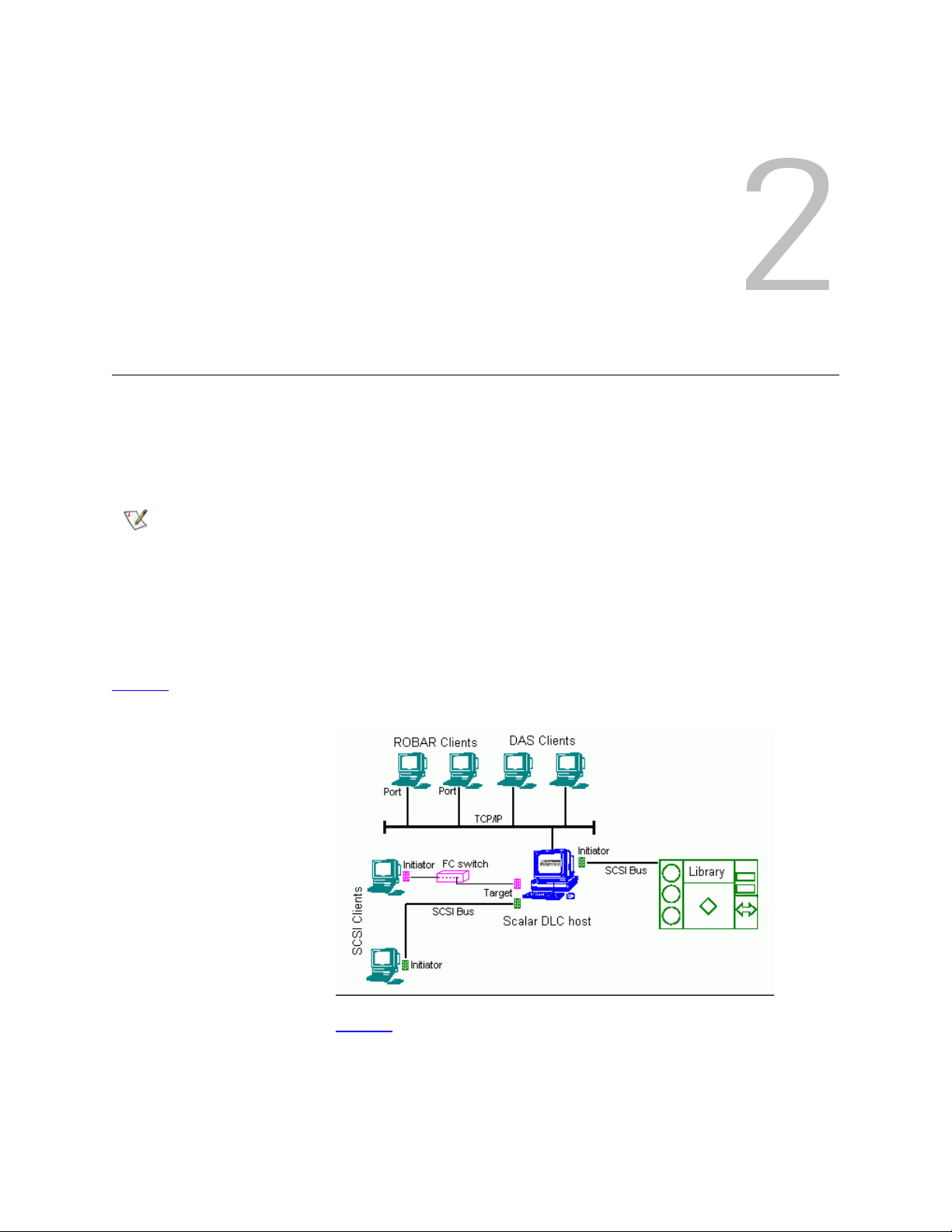
Figure 1
Figure 1 Scalar DLC Structure
illustrates the structure of a typical Scalar DLC system.
Figure 2 illustrated the data flow and the Scalar DLC components.
Installation Guide 3
Page 10
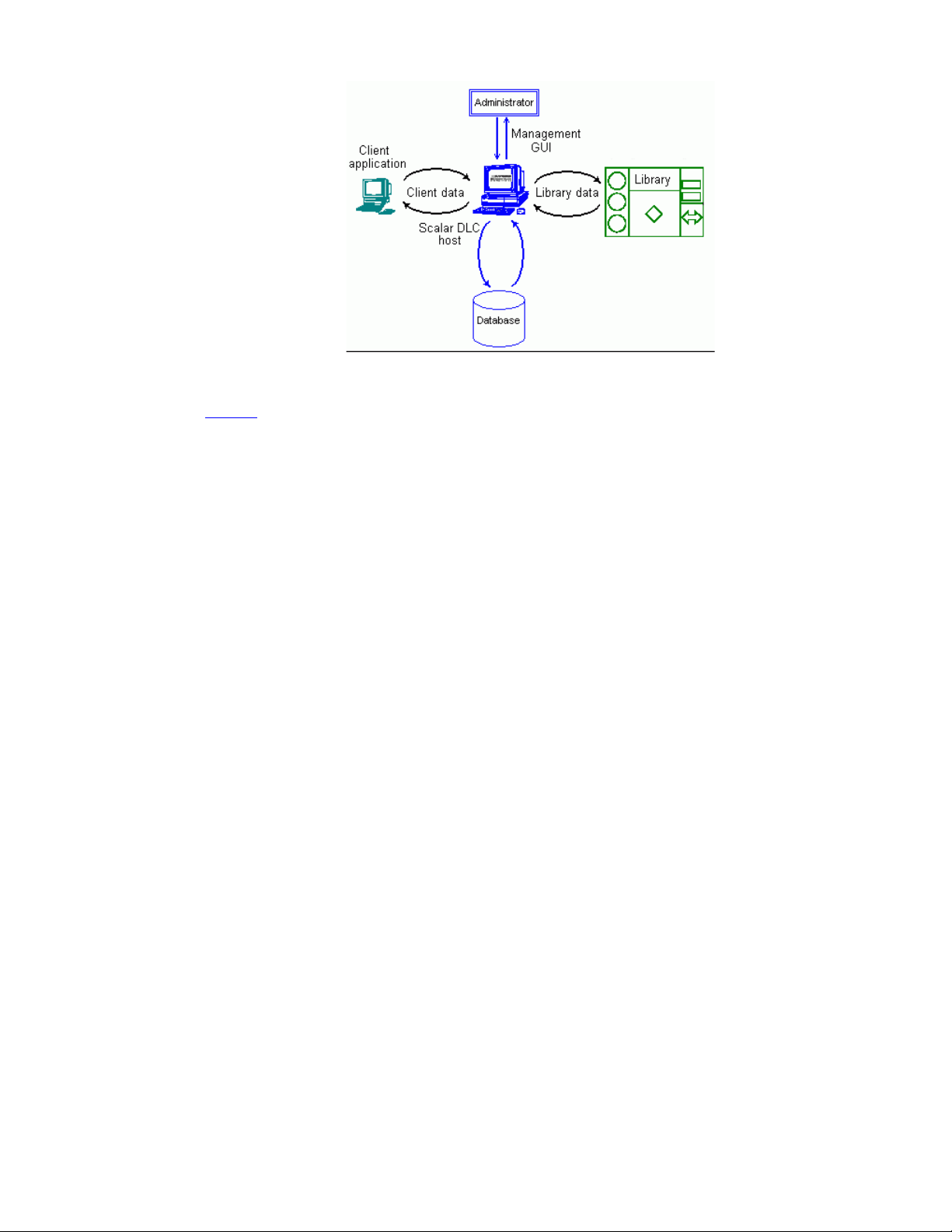
Figure 2 Scalar DLC
Components
As shown on figure 2, the client (user/backup application) sends the request/command to the Scalar DLC
host (server) via the client interface; several interfaces are used (SCSI/FC, DAS, and ROBAR).
Depending on the request, the Scalar DLC either should search the information in the database and send
the response back to the client, or transfer the command to the library via the libr ary inte rf ac e.
After the library has executed the requested op er a tion , th e re sp on se is sent ba ck to the Scala r DLC
indicating that the operation was executed.
The Scalar DLC server updates the database according to the information received from the library and
transfers the response (operation executed) back to the client.
The Management GUI serves as the configuration tool to create a working configuration for clients, and also
as the monitoring tool for the Administrator when it is necessary to watch the system activity.
The details for using Management GUI and other tools of the Scalar DLC software are described in the
Scalar DLC Reference Guide.
4 System Description
Page 11

Platforms
The Scalar DLC software can be installed on the operating systems (platforms) listed in table 1.
Table 1 Scalar DLC Platforms
OS/Platform Service Pack Referred as
32-bit Windows
Server 2003
Enterprise Edition
32-bit Windows
Server 2003
Standard Edition
Windows 2000
Advanced Server
Windows 2000
Server
The OS update with the required hot fixes and/or service packs is performed on regular basis, see Securing
the Scalar DLC on page 135.
SP1 Windows 2003 Server
SP1 Windows 2003
SP4 Windows 2000 Advanced Server
SP4 Windows 2000
Solutions
According to the customer requirements, the Scalar DLC introduce a basic (standar d) solution or a failover
(redundant, cluster) solution. The latter can be provided in plain version and in self-domain version, also
called the self-domain solution. See <Teal underline>Standard Solution on page 4, <Teal
underline>Failover Solution on page 5, and <Teal underline>Self-Domain Solution on page 5.
Depending on the library used by the customer, the solution and system co nfiguration shou ld be sele cted,
as shown in table 2
.
Table 2 Libraries, Solutions, and OS/Platform
Library Scalar DLC Solution OS/Platform
Scalar 10K Failover / Self-domain Windows 2000 Advanced Server
Windows 2003 Server
Standard Windows 2000 (all platforms)
Windows 2003 (all platforms)
Scalar 10K
dual-aisle
(DA)
Installation Guide 5
Failover / Self-domain Windows 2000 Advanced Server
Windows 2003 Server
Standard (only as an
exception)
Windows 2000 (all platforms)
Windows 2003 (all platforms)
Page 12

Standard Solution
The Scalar DLC standard (basic) solution keeps all Scalar DL C components (server, database) on a single
host / PC that is connected to both the library and client(s). The client can work with the library when the
Scalar DLC software is started and the library is online.
The Scalar DLC standard solution requires a single PC, the libr ary , an d the in te rfac e cabl es to provide the
connection between PC (Scalar DLC host) and lib r ary. Additional cabling may be required to provide the
client connections (SCSI/FC) and using SNC.
For the requirements and installation instructions see Setting Up the Standard Solution
on page 7.
Failover Solution
The Scalar DLC Failover (redundant, cluster) solution is provided for the clients using the Microsoft Cluster
service. This solution allows the user to have a shared disk with the Scalar DLC database and two hosts
containing the installed components of Scalar DLC software; for redundancy reasons, one host is online
and the other is offline. If an error occurs and the online Scalar DLC host turns offline, the other host is
immediately online, so the user may not even notice there has been a problem with the host, and the
customer engineer can work with the problem host without stopping the work of Scalar DLC software.
The Scalar DLC failover solution requires two identical PCs, a RAID system, the library, and the interface
cables to provide the connections between PCs (Scalar DLC hosts), RAID (shared database) , and librar y.
Additional cabling may be required to provide the client connections (SCSI/FC) and using SNC.
For the requirements and installation instructions, see Setting Up the Failover Solution
on page 13.
Self-Domain Solution
From version 2.5, Scalar DLC also offers a self-domain solution. This configuration of the Scalar DLC acts
the same way as basic failover solution and has the same har dw ar e requ ir em e nts , ho wever it is installed
without an external domain controller, thus the setup does not exactly duplicate the failover solution
instructions.
In terms of the network security, the self-domain solution is the most reliable method that Scalar DLC
currently can provide.
For the details see Setting Up the Self-Domain Solution
6 System Description
on page 33.
Page 13

Compatibility Matrix
The Scalar DLC compatibility with other hardware and third-party applications is described in table 1.
Table 1 Scalar DLC
Compatibility Matrix
Software/Hardware SW/FW Level
Scalar 10K (both single- and dual-aisle models) 320A.00004
SNC 5100 4.45.22
Scalar DLC 2.7
RMU 210A
AMC 4.5.1
SNMS (StorNext Management System) 2.7
LTO-1 5AU1 (SCSI/FC)
LTO-2 67U1 (SCSI/FC)
LTO-3 64D0 (FC)
LTO-4 75X2
AIT-2 0203 001
AIT-3 0209_0001
DLT8000 V80
SDLT 220 V94
SDLT 320 V96
3590 D0IF_2D4
3592 D310_A0D
TS1120 D3I1_B25
Installation Guide 7
Page 14

8 System Description
Page 15
Setting Up the Scalar DLC
Depending on the configuration used, follow the setup instructions:
• Setting Up the Standard Solution
• Setting Up the Failover Solution
• Setting Up the Self-Domain Solution
Review also Common Setup Notes
solutions only, other instructions are for all solutions.
.
on page 13.
on page 33.
on page 44. Some instructions are for Failover and Self-domain
Setting Up the Standard Solution
The Scalar DLC standard solution can be installed on any Windows 2000 or Windows 2003-b ased system.
• Check the system requirements. Depending on the tape device used with the Scalar DLC, Single-
aisle Requirements on page 7 is for the single-aisle library, and Dual-aisle Requirements on page
8 is for the dual-aisle library.
• Follow the Setup Roadmap
Single-aisle Requirements
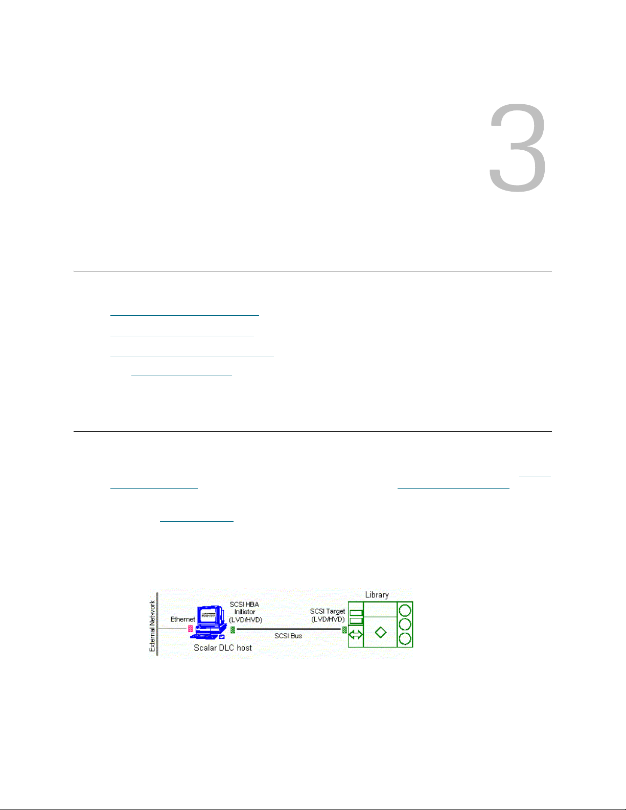
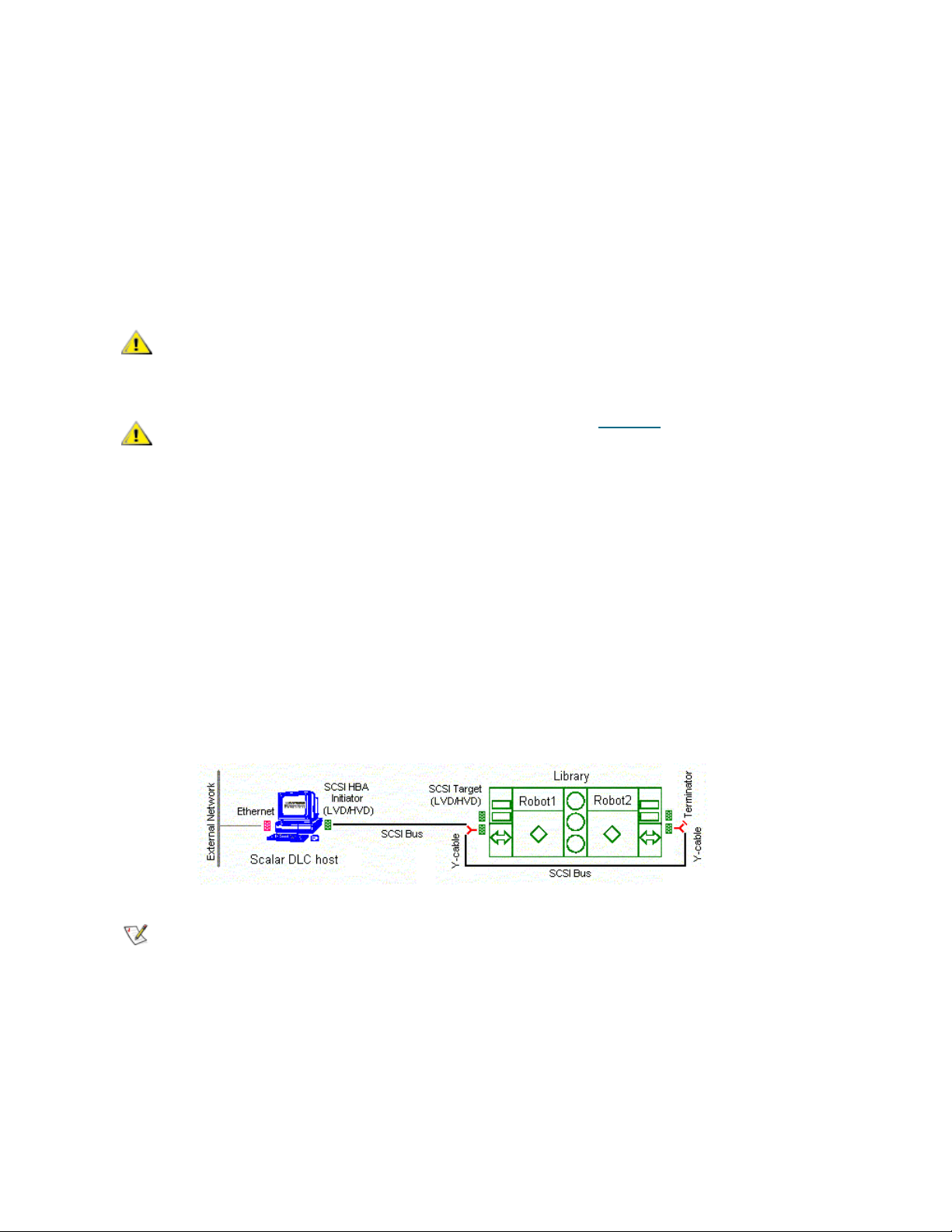
Figure 1 Scalar DLC Basic Solution: Single-aisle
on page 9 to set up the Scalar DLC.
The minimum PC system hardware requirements are summarized in following list.
•A single PC:
• 1G MHZ or faster Intel Xeon or equivalent CPU
• 512 MB RAM
• Dual 18Gb SCSI Hard Drives
Installation Guide 9
Page 16
• Single On-Board NICS (build-in Ethernet)
CAUTION
CAUTION
Note
• CD-RW
• 3.5” inch Diskette Drive
*Required for 2.5 installation only
• Redundant AC Power
• 15" or greater SVGA Display
• Standard keyboard & mouse
• NT/2000 compliant LVD/HVD SCSI initiator adapter, library connection
Do not use anteries (brand) SCSI adapters that do not allow setting reset on
startup via BIOS.
Adaptec 39160 is an LVD/SE adapter, so note Table 16 on page 71 when
choosing SCSI adapter for the library.
• 1 middle length (2-3 m) SCSI cable (68 pins) for the library connection.
• Recovery CD (Windows 2000 or 2003)
The following hardware (not shown on the scheme) is optional.
• SCSI/FC target adapter(s)
• Appropriate SCSI/FC cable(s)
• Fibre Channel switch
•SNC
Dual-aisle Requirements
Figure 2 Scalar DLC Basic Solution: Dual-aisle
Although it is not recommended to use DA libraries in a Scalar DLC standard solution,
this configuration is possible.
The minimum PC system hardware requirements are summarized in following list.
•A single PC:
• 1G MHZ or faster Intel Xeon or equivalent CPU
• 512 MB RAM
• Dual 18Gb SCSI Hard Drives
• Single On-Board NICS (build-in Ethernet)
10 Setting Up the Scalar DLC
Page 17

• CD-RW
CAUTION
CAUTION
• 3.5” inch Diskette Drive
*Required for 2.5 installation only
• Redundant AC Power
• 15" or greater SVGA Display
• Standard keyboard & mouse
• NT/2000 compliant LVD/HVD SCSI initiator adapter, library connection
Do not use anteries (brand) SCSI adapters that do not allow setting reset on
startup via BIOS.
Adaptec 39160 is an LVD/SE adapter, so note Table 16 on page 71 when
choosing SCSI adapter for the library.
• 1 middle length (2-3 m) SCSI cable (68 pins) for the library connection.
• 1 middle length (4-5 m) SCSI cable (68 pins) for the aisle connection.
The total length of two SCSI cables required for the dual-aisle library connection (see Figure 4
page 8) must not exceed 12 m for LVD adapters and 25 m for HVD adapters.
on
• 2 SCSI Y-block connectors (Y-cable) to terminate the SCSI Bus on library.
• 1 SCSI Terminator, LVD/HVD for the library connection.
• Recovery CD (Windows 2000 or 2003)
The following hardware (not shown on the scheme) is optional.
• SCSI/FC target adapter(s)
• Appropriate SCSI/FC cable(s)
• Fibre Channel switch
•SNC
Setup Roadmap
Complete the following steps to set up the basic solution.
1 Collecting Setup Data
2 Setting Up the Host
3 Installing the Scalar DLC Software
4 Configuring the Logical Library
For the optional additional activity, see Setting Up the Library
page 131, and Host/Library Communication using Fibre Channel and SNC
Remove, Repair on page 81.
on page 9.
on page 10.
on page 12.
on page 12.
on page 123, Building Client Connections on
on page 127. See also Upgrade,
Collecting Setup Data
Collect the following information before starting setup.
• Computer
Installation Guide 11
Page 18

• computer name (max 14 symbols)
Note
Note
• public IP address
• public Subnet mask
• public default Gateway
• public preferred DNS
• public Alternate DNS
• public Primary WINS
• public Secondary WINS
• private IP address
• private subnet mask
• Local administrator login name and password
• Scalar DLC serial number
• Domain
• domain name
• domain admin login name and password
Table 3 Standard Solution: Installation Time
Installation procedure Time
Provide cabling and setup for PC system 10 min
Set IP address and computer name 10 min
Install Scalar DLC on PC 50 min
Setting Up the Host
Step 1 Set up the host hardware (network adapters, SCSI and FC ada pters if required). Note Table 18
on page 72.
Step 2 Connect the PC to a local network. Install Windows 2000 / 2003. Resolve the network name
and TCP/IP. Join the PC to the domain, if required (domain admin password is required).
Enter BIOS. Go to Chipset section. Hyper threading parameter should be disabled.
Step 3 Install all required software services, for example, antivirus packages and firewall. Install all
required device drivers (for example, initiator SCSI and RAID). Install the latest Microsoft
Service Pack (SP4 for Win2000 and SP1 for Windows 2003 is required).
For installation and re-installation of all 2.6 configurations, use the Recovery CD. The
Recovery CD contains the appropriate drivers and the requ ire d SP1 installations.
Step 4 When the operation system is installed successfully, reboot and ensure all services work
correctly.
12 Setting Up the Scalar DLC
Page 19

Note
Unplug the target card SCSI cable if the server has trouble booting (may be a termination
Note
Note
problem).
Configuring SCSI for Library
Step 1 Configure the SCSI ID's for the LVD/HVD adapter connected to the library.
•Set termination mode to automatic
•Set Reset SCSI Bus parameter to disabled
• Set the SCSI ID of this board to 5
Adapter ID must not overlap with the single aisle LIBRARY SCSI ID.
Adapter ID must not overlap with the either
libraries.
Any number could be used as SCSI IDs as long as it follows the rules above.
Step 2 Log on. Update drivers (Adaptec, QLA, etc.) as described in Updating Drivers
Step 3 Reboot host PC.
of the LIBRARY SCSI IDs for the dual-aisle
Setting Up IP Address, Host Name, and Joining Domain
Step 1 Log in host PC as administrator.
Step 2 Set up Public network.
• <pause> Right click “My Network Places” and select “Properties”.
• Right click “Local Area Connection” and rename it to ‘Public’. Select “Properties”.
• Select “Show Icon in the Task Bar when Connected”.
• Select “Internet Protocol (TCP/IP)” and select “Properties”.
• Select “Use the Following IP Address”
•Set IP Address (208.230.5.100 in lab)
on page 110.
•Set Subnet Mask to 255.255.255.0
•Set Preferred DNS Server to 208.230.5.4 (in lab)
Also enter any additional customer networking information (additional DNS, WINS etc.).
• Press “OK” and “OK”.
Step 3 Join computer to the domain
• Right click “My Computer” and select “Properties”.
• (on Windows 2000) Open “Network Identification” and select “Properties”.
Installation Guide 13
Page 20
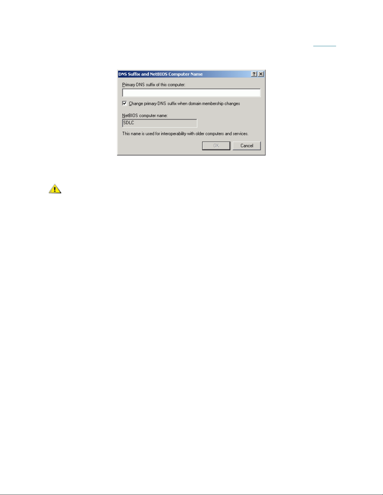
• (on Windows 2003) Open Computer Name > Change > More. Ensure that the checkbox
CAUTION
‘Change primary DNS suffix when domain membership changes’ is enabled (see Figure 5
on page 12). Press OK.
Figure 3 Windows 2003: DNS suffix enabled
• Set “Computer name” (SDLC)
Computer name must not be longer than 14 symbols.
• Select “Domain” and enter <domain name without postfix> and OK (“domain” for lab)
• Enter domain admin name and password and OK (“adicuser” and “pa$$w0rd”)
•Wait for Welcome to domain.
• Press “OK” and then “OK” to reboot. Press “OK” and then “Yes”.
Step 4 Press ‘Yes’ to reboot now. Wait until reboot completes.
14 Setting Up the Scalar DLC
Page 21

Installing the Scalar DLC Software
CAUTION
Step 1 Log in as administrator or as a domain user with the local administration rights.
Step 2 If it has not already been done, set up the library media changer. See Setting Up the Library
page 123.
Step 3 Install the Scalar DLC software with all required components (see Installing the Scalar DLC
page 45).
Do not install Scalar DLC Clustering until both nodes are fully installed with
Scalar DLC.
on
on
Configuring the Logical Library
Step 1 Log in as administrator or as a domain user with the local administration rights and start the
Scalar DLC software if it is not started automatically.
Step 2 Double click Scalar DLC Manager to start the Scalar DLC Management GUI from a local
computer. From a remote computer, use
http://ScalarDLC-machine-name in current browser.
Step 3 The first start of the Scalar DLC Management GUI launches the configuration engine. Select
either the Automatic or Manual configuration option to configure the logical library
automatically. If more than one logical library should be created, select the Advanced
configuration option. Refer to the Configuration chapter of the Scalar DLC Reference Guide for
the instructions.
Setting Up the Failover Solution
The Scalar DLC Failover (Redundant, Cluster) solution can be installed only on a Windows 2000 Advanced
Server or Windows 2003 Enterprise Server because it uses the Microsoft Cluster Service that is not
available under Windows 2000 Professional, Windows 20 00 Server, an d Windows 2003. Cluster ing is only
provided on the Windows 2003 Enterprise CD.
• Check the system requirements. Depending on the tape device used with the Scalar DLC, Single-
aisle Requirements on page 13 is for the single-aisle library, and Dual-aisle Requirements on page
14 is for the dual-aisle library.
• Follow the Setup Roadmap
on page 15 to set up the Scalar DLC.
Installation Guide 15
Page 22
Single-aisle Requirements
CAUTION
CAUTION
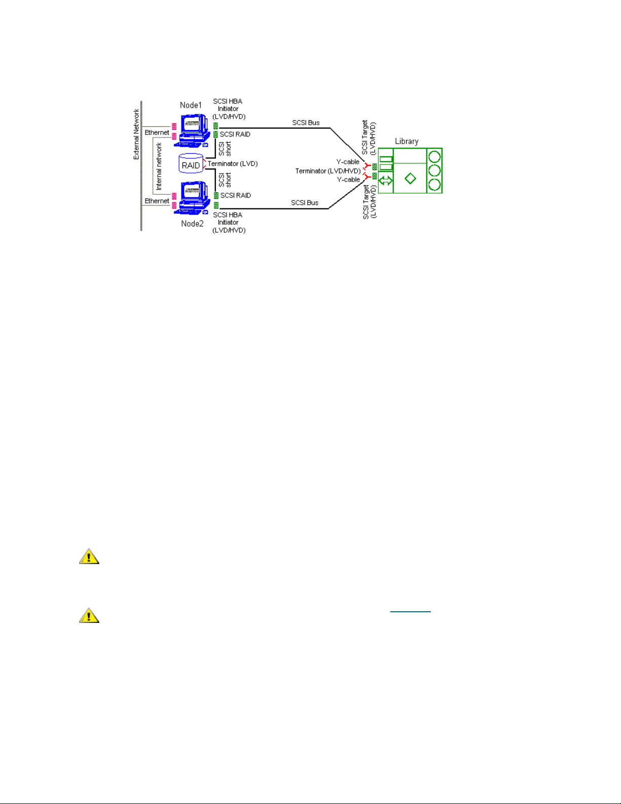
Figure 4 Scalar DLC Failover Solution: Single-aisle
The minimum PC system hardware requirements are summarized in following list.
• Two PCs with identical hardware and software:
• 1G MHZ or faster Intel Xeon or equivalent CPU
• 512 MB RAM
• Dual 18Gb SCSI Hard Drives
• PERC3-DI, 128MB Battery Backed Cache, two Internal Channel - Embe dded RAID Controlle r
(1, 2 Drives connected to on-board RAID)
• Dual On-Board NICS (build-in Ethernet)
• CD-RW
• 3.5” inch Diskette Drive
*Required for 2.5 installation only
• Redundant AC Power
• 15" or greater SVGA Display
• Standard keyboard & mouse
• NT/2000 compliant LVD SCSI initiator adapter, RAID connection
• NT/2000 compliant LVD/HVD SCSI initiator adapter, library connection
Do not use anteries (brand) SCSI adapters that do not allow setting reset on
startup via BIOS.
Adaptec 39160 is an LVD/SE adapter, so note Table 16 on page 71 when
choosing SCSI adapter for the library.
• 1 ArrayMasStor P-Series ADTX RAID System.
• 1 Network cross cable (twisted-pair) (~1 m), for the internal cluster network.
• 2 short (~1 m) SCSI cables (68 pins), for the RAID connections.
• 2 middle length (2-3 m) SCSI cable (68 pins), for the library connections.
• 2 Y-Block connectors to terminate the SCSI Bus on library.
• 2 LVD SCSI Terminators for the RAID connections.
16 Setting Up the Scalar DLC
Page 23
• 2 LVD/HVD SCSI Terminators for the library connections.
CAUTION
• Recovery CD (Windows 2000 Advanced Server or 2003 Server)
The hardware configuration of both cluster nodes must be identical, and they
must remain identical. For example, all cards/adapters must be identical and
need to be placed in identical slots.
The following hardware (not shown on the scheme) is optional.
• SCSI/FC target adapter(s)
• Appropriate SCSI/FC cable(s)
• Fibre Channel switch
•SNC
Dual-aisle Requirements
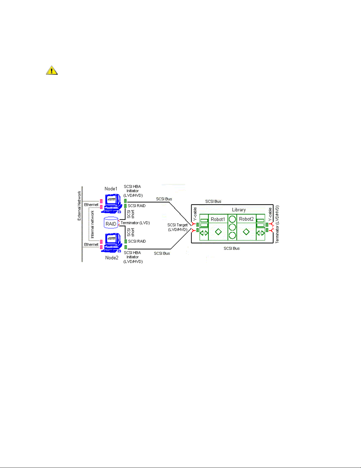
Figure 5 Scalar DLC Failover Solution: Dual-aisle
The minimum PC system hardware requirements are summarized in following list.
• Two PCs with identical hardware and software:
• 1G MHZ or faster Intel Xeon or equivalent CPU
• 512 MB RAM
• Dual 18Gb SCSI Hard Drives
• PERC3-DI, 128MB Battery Backed Cache, two Internal Channel - Embe dded RAID Controlle r
(1, 2 Drives connected to on-board RAID)
• Dual On-Board NICS (build-in Ethernet)
• CD-RW
• 3.5” inch Diskette Drive
*Required for 2.5 installation only
• Redundant AC Power
• 15" or greater SVGA Display
• Standard keyboard & mouse
• NT/2000 compliant LVD SCSI initiator adapter, RAID connection
• NT/2000 compliant LVD/HVD SCSI initiator adapter, library connection
Installation Guide 17
Page 24

CAUTION
Do not use anteries (brand) SCSI adapters that do not allow setting reset on
CAUTION
CAUTION
startup via BIOS.
Adaptec 39160 is an LVD/SE adapter, so note Table 16 on page 71 when
choosing SCSI adapter for the library.
• 1 ArrayMasStor P Series ADTX RAID System.
• 1 Network cross cable (twisted-pair) (~1 m), for the internal cluster network.
• 2 short (~1 m) SCSI cables (68 pins), for the RAID connections.
• 2 middle length (2-3 m) SCSI cable (68 pins), for the library connections.
• 2 middle length (4-5 m) SCSI cable (68 pins), for the aisle connections.
The total length of two SCSI cables required for the dual-aisle library connection (see Figure 7
page 14) must not exceed 12 m for LVD adapters and 25 m for HVD adapters.
• 4 Y-Block connectors to terminate the SCSI Bus on library.
• 2 LVD SCSI Terminators for the RAID connections.
• 2 LVD/HVD SCSI Terminators for the library connections.
• Recovery CD (Windows 2000 Advanced Server or 2003 Server)
on
The hardware configuration of both cluster nodes must be identical, and they
must remain identical. For example, all cards/adapters must be identical and
need to be placed in identical slots.
The following hardware (not shown on the scheme) is optional.
• SCSI/FC target adapter(s)
• Appropriate SCSI/FC cable(s)
• Fibre Channel switch
•SNC
Setup Roadmap
Complete the following steps to set up the Failover solution.
1 Collecting Setup Data
2 Installing the Nodes
3 Installing ADTX RAID
4 Configuring SCSI for RAID and Library
5 Setting Up IP Address, Node Name, and Joining Domain
on page 16.
on page 17.
on page 18.
on page 20.
on page 22.
6 Setting Up the RAID
7 Configuring Cluster Service
8 Installing Scalar DLC Software
9 Configuring the Logical Library
18 Setting Up the Scalar DLC
on page 24.
on page 26
on page 28.
on page 31.
Page 25

For the optional additional activity, see Setting Up the Library on pa ge 123, Building Client Connections on
page 131, Installing SCSI/FC Target Adapters on a Live Machine
Communication using Fibre Channel and SNC on page 127. See also Upgrade, Remove, Repair on page
81.
on page 134, and Host/Library
Collecting Setup Data
Collect the following information before starting setup.
• Nodes
• Node1 computer name (14 symbols max)
• Node1 public IP address
• Node2 computer name (14 symbols max)
• Node2 public IP address
• public Subnet mask
• public default Gateway
• public preferred DNS
• public alternate DNS (optional)
• public primary WINS (optional)
• public secondary WINS (optional)
• Node1 private IP address
• Node2 private IP address
• private subnet mask
• Local administrator login name and password (same on both nodes)
• Scalar DLC serial number (same on both nodes
• Cluster
• name (14 symbols max)
• IP address
• Subnet mask = public subnet mask
• Domain
•name
• domain admin name and password
• directory services restore mode password
Table 4 Failover Solution: Installation Time
Installation procedure Time
Provide cabling and setup for dual PC failover system 30 min
SCSI configuration for RAID and library 20 min
Set IP addresses and computer names 30 min
Configure primary and secondary domain controllers 45 min
Installation Guide 19
Page 26
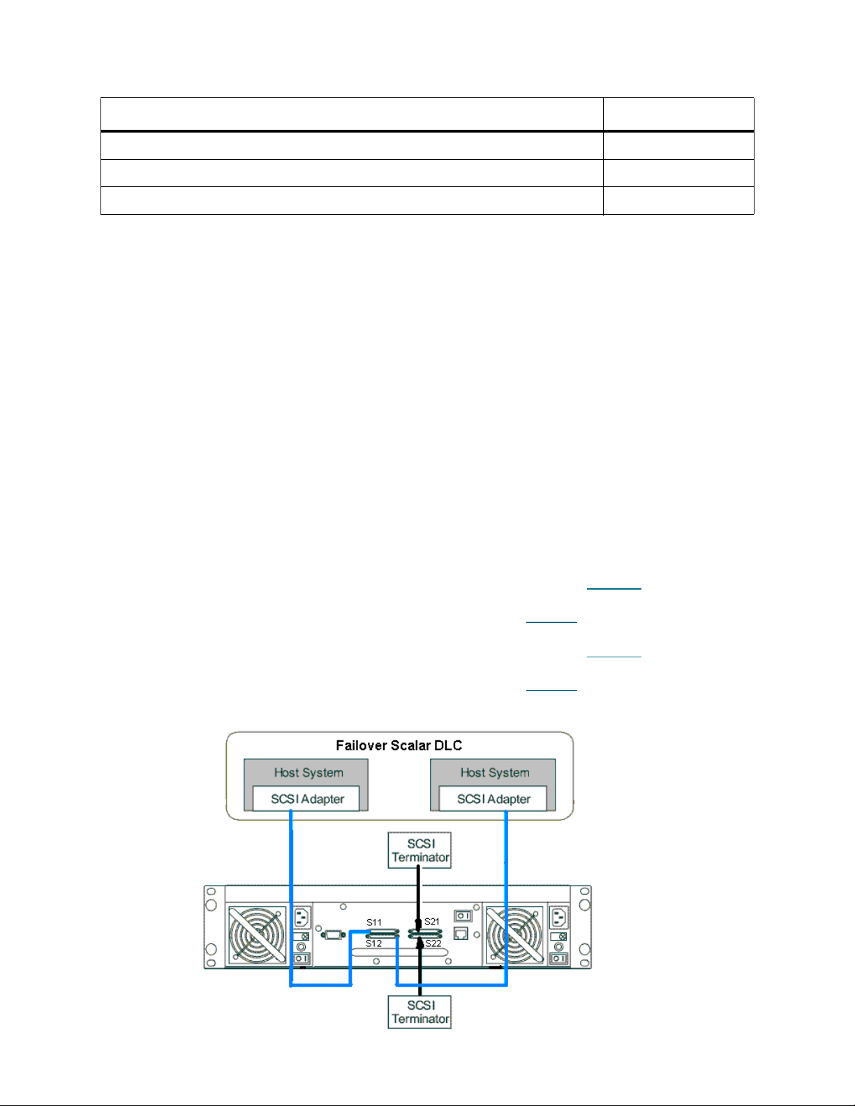
Table 4 Failover Solution: Installation Time (Continued)
Installation procedure Time
Setup RAID 10 min
Configure cluster service 20 min
Install Scalar DLC on both PC 120 min
Active Directory Account Information
Contact the local network administrator and ensure that the following settings are performed.
• User account created with domain admin rights and the following options:
• User must not change password under next logon.
• User cannot change password.
• Password never expires.
• All other options are disabled.
• Logon hours for this user are set to 24/7.
• Log on rights are set either to all computers or to all Scalar DLC nodes.
Installing the Nodes
Step 1 Turn off external RAID.
Step 2 Insert the RAID SCSI HBA into the PCI slot of Node1 according to Table 18
Connect it and RAID SCSI channel (S11) with the short SCSI cable. Terminate the second
RAID SCSI channel (S21) with the SCSI terminator (see Figure 8
Step 3 Insert the RAID SCSI HBA into the PCI slot of Node2 according to Table 18 on page 72.
Connect it and RAID SCSI channel (S12) with the short SCSI cable. Terminate the second
RAID SCSI channel (S22) with the SCSI terminator (see Figure 8
Figure 6 RAID SCSI cabling
on page 18).
on page 18).
on page 72.
20 Setting Up the Scalar DLC
Page 27

Step 4 Connect the monitor, keyboard, mouse, and KVM.
Note
Step 5 Boot Node1. Log on (administrator / password).
Enter BIOS. Go to Chipset section. Hyper threading parameter should be disabled.
Step 6 <pause> select “I will configure the server later” and press Next. Clear “Show This Screen on
Startup” and close window.
Step 7 Shutdown Node1.
Step 8 Repeat steps 4 to 7 for Node2.
Step 9 Connect ethernet cables LAN 1 (public network) and LAN 2 (private network).
Installation Guide 21
Page 28

Installing ADTX RAID
Step 1 Power on RAID.
Step 2 Set SCSI ID.
• The default setting is SCSI ID 0 for both channels. In order to verify the SCSI ID for both
channels use the Operator Panel on the RAID.
RAID SUBSYSTEM
•MAIN MENU
• [MAIN MENU]
♥ SYSTEM INFO
• [MAIN MENU]
♥ VIEW CONFIG
• [VIEW CONFIG]
♥ SCSI
• [SCSI]
♥ CHANNEL 1
♥ SCSI ID
♥ 0
The same steps for channel 2.
• In order to change the SCSI ID for both channels use the following steps.
RAID SUBSYSTEM
•MAIN MENU
• [MAIN MENU]
♥ SYSTEM INFO
• [MAIN MENU]
♥ CHANGE CONFIG
• ENTER PASSWORD 1234
• [CHANGE CONFIG]
♥ SCSI
• [SCSI]
♥ CHANNEL 1
♥ SCSI ID
♥ SET 0
The same steps for channel 2.
Step 3 Change the RAID 'WRITE CACHE' setting.
• In order to change the RAID 'WRITE CACHE' setting via Operator Panel use the following
steps.
RAID SUBSYSTEM
•MAIN MENU
22 Setting Up the Scalar DLC
Page 29
• [MAIN MENU]
♥ SYSTEM INFO
• [MAIN MENU]
♥ CHANGE CONFIG
• ENTER PASSWORD 1234
• [CHANGE CONFIG]
♥ OPTION SETTING
• [OPTION SETTING]
♥ CACHE SETTING
• [CACHE SETTING]
♥ WRITE CACHE
• [WRITE CACHE]
♥ SET 'DISABLE'
Step 4 Reset RAID by turning it off.
Configuring SCSI for RAID and Library
Step 1 Plug the SCSI cable directly in to the RAID vhdci connector.
Step 2 Power on Node1, then power on RAID.
If Write Signature does not appear, the RAID is not initialized.
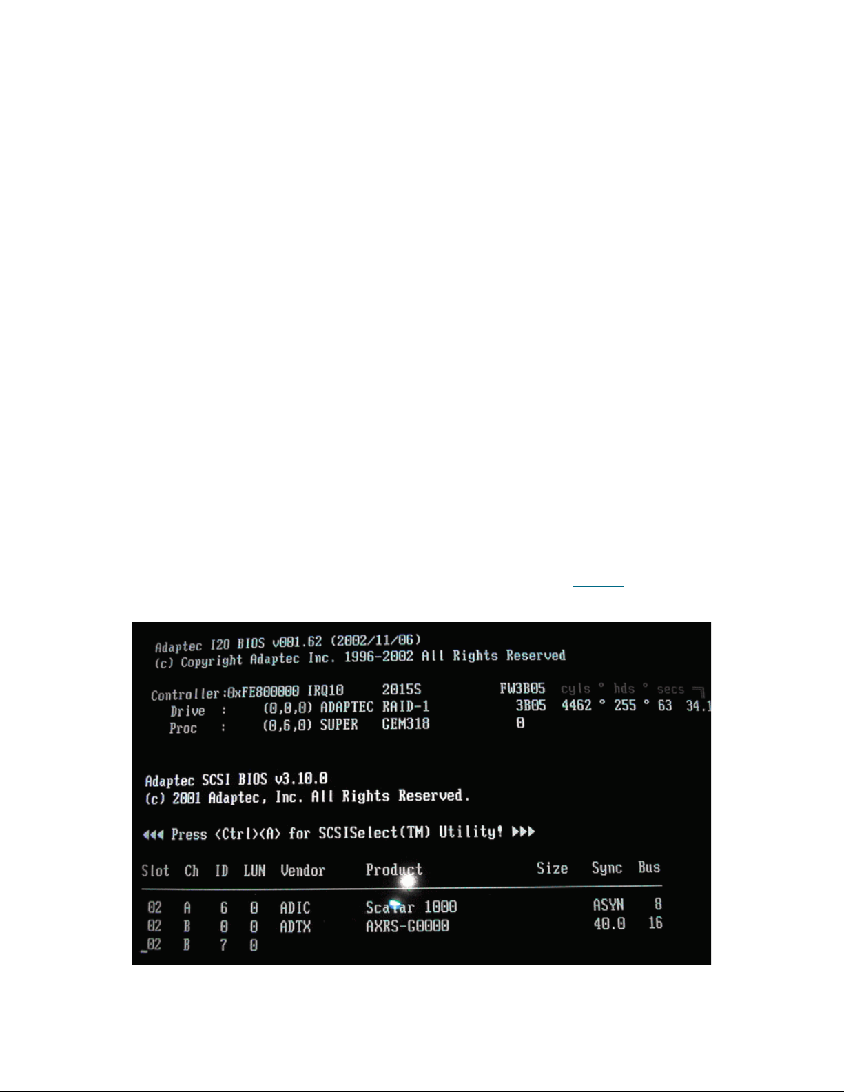
Step 3 <Ctrl>+A to enter Bios for Adaptec SCSI card at Bios 3.10.0 (see Figure 9
Figure 7 Adaptec SCSI Bios
).
• Select B for RAID configuration.
•Select SCSI disk utilities to scan for RAID device.
Installation Guide 23
Page 30
• Press “Esc”.
Note
• Select “Configure / view SCSI settings”.
• Set SCSI controller ID (14 for Node1 and 15 for Node2).
• Set SCSI termination to Automatic.
•Go to Advanced configuration.
• Set “Reset SCSI bus at IC Initialization” to Disabled.
• Set “SCSI controller Int 13 Support“ to Disabled: NOT scan.
• Press “Esc”.
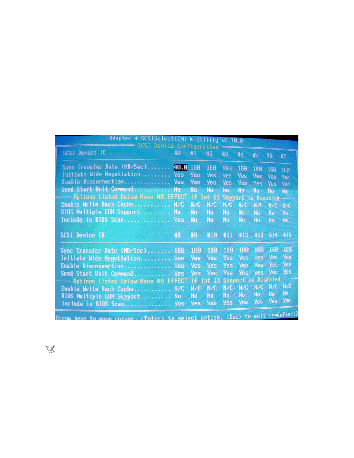
• Go to “SCSI device configuration” (see Figure 10
Figure 8 Adaptec SCSI Bios: SCSI Device Configuration
on page 21).
• Set “Sync Transfer Rate” to 40
Rate is 160 for L and P series RAIDs
• Set “Start unit command” to No for #0.
• Set “Include in Bios scan” to Yes for Node1 and No for Node2 for #0.
• Press “Esc”, and “Esc”, and “Save changes”.
• Press “Esc”.
• Select A for library configuration
• Select “Configure / view SCSI settings”
24 Setting Up the Scalar DLC
Page 31

• Set termination to Automatic
Note
Note
•Go to Advanced configuration
♥ Set “Reset SCSI bus at IC Initialization” to Disabled
♥ Press “Esc”, and “Esc”, and “Save changes”.
• Press “Esc”, and “Esc”, and exit utility.
Step 4 Configure the SCSI ID's for the LVD/HVD adapters (connected to the library) on the cluster
nodes.
• Enter the LVD/HVD SCSI BIOS Setup on Node1 for the adapter connected to the library:
•Set termination mode to automatic
•Set Reset SCSI Bus parameter to disabled
• Set the SCSI ID of this board to 5
• Enter the LVD/HVD SCSI BIOS Setup on Node2 for the adapter connected to the library.
•Set termination mode to automatic
•Set Reset SCSI Bus parameter to disabled
• Set the SCSI ID of this board to 6
Both adapters must have different SCSI IDs.
Adapter IDs must not overlap with the single aisle LIBRARY SCSI ID.
Adapter IDs must not overlap with the either
of the LIBRARY SCSI IDs for the dual-aisle
libraries.
Any number could be used as SCSI IDs as long as it follows the rules above.
Step 5 Log on. Update drivers (Adaptec, QLA, etc.) as described in Updating Drivers
Step 6 Shutdown Node1.
Step 7 Repeat steps 2 - 5 using Node2 instead of Node1.
Step 8 Initialize LUN 0.
To initialize LUN 0, go to Main Menu > Change Configuration > Password
In the Password field, type: 1 2 3 4
then Raid Config > Initialize LU
In the Initialize LU field, type: Yes
On the keyboard, press 0
on page 110.
The RAID initialization takes a minimum of 3 hours.
Installation Guide 25
Page 32

Setting Up IP Address, Node Name, and Joining Domain
Note
Note
Step 1 Power on Node1 and log in.
“HDD changed” message may appear. F1 to enter setup and esc and ok.
During logging in ignore duplicate name message if it appears.
Step 2 Set up Public network.
• <pause> Right click “My Network Places” and select “Properties”.
• Right click “Local Area Connection” and rename in to ‘Public’. Select “Properties”.
• Select “Show Icon in the Task Bar when Connected”.
• Select “Internet Protocol (TCP/IP)” and select “Properties”.
• Select “Use the Following IP Address”
•Set IP Address (208.230.5.100 for Node1 and 208.230.5.200 for Node2 in lab)
•Set Subnet Mask to 255.255.255.0
•Set Preferred DNS Server to 208.230.5.4 (in lab)
•Set Public default Gateway to 208.230.5.4 (in lab)
Also enter any additional customer networking information (additional DNS, WINS etc.).
• Press “OK” and “OK”.
Step 3 (This step is for Windows 2000 system only. On Windows 2003 follow the Step 4)
Right click “Public” and “Disable” then right click and “Enable”. A new item “Local Area
Connection 2” will appear.
Step 4 Set up Private network
• Right click “Local Area Connection 2” and rename it to ‘Private’. Select “Properties”
• Select “Show Icon in the Task Bar when Connected”
• Select “Internet Protocol (TCP/IP)” and select “Properties”
• Select “Use the Following IP Address”
• Set IP Address to (10.10.10.1 and 10.10.10.2 in lab) (use here a completely different IP
than for “Local Area Connection”).
• Set Subnet Mask to 255.0.0.0.
• Press “OK” and “OK”.
Step 5 (This step is for Windows 2000 system only. On Windows 2003 follow the Step 6)
Right click “Local Area Connection 2” and “Disable” then right click and “Enable”.
Step 6 Join node to the domain
• Right click “My Computer” and select “Properties”.
26 Setting Up the Scalar DLC
Page 33

• (on Windows 2000) Open “Network Identification” and select “Properties”.
CAUTION
CAUTION
• (on Windows 2003) Open Computer Name > Change > More. Ensure that the checkbox
‘Change primary DNS suffix when domain membership changes’ is enabled (see Figure
11). Press OK.
Figure 9 Windows 2003: DNS suffix enabled
• Set “Computer name” (sdlc1 for Node1 and sdlc2 for Node2)
Both Node1 and Node2 names must not be longer than 14 symbols.
• Select “Domain” and enter <domain name without postfix> and OK (“domain” for the computers
in lab)
• Enter domain user name and password and OK (“adicuser” and “pa$$w0rd”)
•Wait for Welcome to domain.
• Press “OK” and “OK” to reboot and “OK” and “Yes”.
Step 7 ‘Yes’ to reboot now. Wait until reboot.
Step 8 Repeat steps 1 to 6 for Node2. ‘No’ to reboot now.
Using Start > Run do the following:
From Node2 run: ping <Node1 public IP address>
From Node2 run: ping <Node1 private IP address>
From Node1 run: ping <Node2 public IP address>
From Node1 run: ping <Node2 private IP address>
From Node1 or Node2 run: ping <Domain name>
If any of these commands returns “Request timed out“ response, that mea ns
the network settings are configured incorrectly, for example, the network
connection that has been configured as ‘public’, is in fact internal cluster
(private) network connection.
Step 9 Shutdown both nodes.
Installation Guide 27
Page 34

Setting Up the RAID
Same on both Windows 2000 and Windows 2003 unless the other specified.
Step 1 Power up Node1 and log in as Administrator for SDLC1 (this computer)
Step 2 Prepare to Format RAID disk
• Right click “My Computer” and select “Manage”.
• Select Device Manager and open Disk Drives. Scan for new devices (see Figure 12
Figure 10 Device Manager: Disk Drives
).
• Verify that the ADTX RAID is present.
• Select “Disk Management”. Write Signature Wizard should start. Press “Next”.
If Write Signature does not appear, the RAID is not initialized. Return to Step 1.
• Select “Disk 1” to write a Signature and press “Next”.
• Unselect “Disk 1” to Upgrade (Convert on Windows 2003), press “Next” and then “Finish”.
Step 3 Format RAID
• Right click unallocated space and select “Create Partition”. Create Partition Wizard starts. Click
Next.
• Select “Primary Partition” and press “Next”.
• Set maximum value in “Amount of Disk Space to Use” and press “Nex t”.
• Select “Assign a Drive Letter” and select “R :” and press “Next”.
• Select “Format this Partition with the Following Settings”
• Set “File System” to “NTFS”
• Set “Allocation Unit Size” to “Default”
28 Setting Up the Scalar DLC
Page 35

• Set “Volume Label” to “RAID”
• Select “Perform A Quick Format” (see Figure 13
Figure 11 Format RAID Partition
• Press “Next” and “Finish” and let format complete.
)
• Shutdown Node1, turn RAID off.
Step 4 Power up Node2 and log in as Administrator for SDLC2 (this computer). Turn RAID on and wa it
for it to come ready.
Step 5 Join RAID disk
• Right click “My Computer” and select “Manage”.
• Select Device Manager and open Disk Drives. Scan for new devices.
• Verify that the ADTX RAID is present.
• Select “Disk Management”. Right click “RAID”. Select “Change Drive Letter and Path”.
• Select “Edit” and “Assign Drive Letter” to “R”. Press OK. Press “Yes” to confirm.
• Shutdown Node2.
Configuring Cluster Service
Under WIndows 2000 and Windows 2003 the cluster is installed differently.
Windows 2000
Step 1 Power up Node1 and log in as Administrator to SDLC1 (this computer)
Step 2 Configure Cluster Service on Node1.
•Select Start > Settings > Control panel > Add/Remove Programs > Add/Remove Windows
Components >> Cluster Service. Press Next.
Installation Guide 29
Page 36

• Insert Windows 2000 Advanced Server SP4 CD and press OK. Cluster Service Configuration
CAUTION
Wizard will start. Press “Next”.
• Click “I Understand” and “Next”.
• Select “The First Node in the Cluster” and “Next”.
• Set cluster name to SDLC-CLUSTER and “Next”.
The cluster name must not be longer than 14 symbols.
• Set User Name to “adicuser” and Password to “pa$$w0rd”. Set Domain to <domain> and
“Next”.
• Click “Yes” to adding account to the Administrators Group.
• Ensure that “R: Raid” is in managed disks and “Next”.
• Select “R: Raid” and “Next” and “Next”.
• Set up Cluster Network
• For Network Name “Public” select “Enable this Network for Cluster Use”.
• Select “All Communications (mixed network)” and “Next”.
• For Network Name “Private” select “Enable this network for cluster use”.
• Select “Internal Cluster Communications Only (Private Network)” and “Next”.
• Ensure that “Private” is at the top of Networks list and “Next”
♥ Set “Cluster IP address” to <ip address> (208.230.5.3 in lab)
♥ Set “Subnet Mask” to 255.255.255.0
♥ Set “Network” to “Public” and “Next”.
• “Finish” and “OK” to Cluster Service Started Successfully.
• Finish and eject CD and close all windows.
Step 3 Power up Node2 and log in as Administrator for SDLC2 (this computer)
Step 4 Configure Cluster Service on Node2.
•Select Start > Settings > Control panel > Add/Remove Programs > Add/Remove Windows
Components >> Cluster Service. Press Next.
• Insert Windows 2000 Advanced Server SP4 CD and press OK.
• Cluster Service Configuration Wizard will start and Next
• Click “I Understand” and “Next”.
• Select “Second or Next Node in the Cluster” and “Next”.
• Set cluster name as SDLC-CLUSTER
• Select “Connect to Cluster As”.
• Set User Name to “adicuser” and Password to “pa$$w0rd”.
• Set Domain to <domain> and “Next”.
• Set password as “pa$$w0rd” and “Next”.
• “Yes” to Specified Account not a Member
30 Setting Up the Scalar DLC
Page 37

• “Finish” and “OK” and “Finish”.
CAUTION
Step 5 Remove CD and close all windows.
Step 6 Verify Cluster service.
• On Node2 select Start > Settings > Control Panel > Administrative Tools > Cluster
Administrator.
• Select Groups > Cluster Group
• Select File > Move Group to verify the cluster is working properly
• Move group again and return ownership to Node1
Windows 2003
Step 1 Power on Node1. Log on as Administrator.
Step 2 Create Cluster on Node1.
• Start > Administrative Tools > Cluster Administrator
• Choose 'Create new cluster' and OK. Next. Enter cluster name (SDLCCLUSTER2003) a nd
Next.
The cluster name must not be longer than 14 symbols.
• Review Node1 name and Next. The wizard will analyze an existing configuration.
• Next. Enter cluster IP (static, unique) and Next.
• Enter domain user account & password. Next.
• Review cluster summary and Next. Wizard creates a cluster.
• Next and Finish.
Step 3 Join Node2 to Cluster
• Power on Node2 and wait till it comes up. Wait circa 5 min until the virtual cluster name will
be available from Node2. Switch to Node2.
• Start > Administrative Tools > Cluster Administrator. Choose 'Open Connection to cluster'
and enter the cluster name (SDLCCLUSTER2003).
• OK. Then Fine > New > Node. Add new Node wizard starts.
• Next. Add, then Next. The wizard will analyze an existing configuration.
• Enter domain user account & password. Next.
• Review cluster summary and Next. Wizard adds node to a cluster.
• Next and Finish. The cluster is ready.
Step 4 Ensure the cluster works.
• Select Start > Administrative Tools > Cluster Administrator
• Select Groups > Cluster Group
Installation Guide 31
Page 38

• Select File > Move Group to verify the cluster is working properly
CAUTION
CAUTION
Note
• Move group again and return ownership to Node1.
Installing Scalar DLC Software
Same on both Windows 2000 and Windows 2003 unless the other specified.
When entering the backup directory information in the required setup
screens and fields, make certain the backup directory information is
accurate. After the installation is complete, verify that the backup directory
path is correct.
Do not install Scalar DLC Clustering until both nodes are fully installed with
Scalar DLC.
Step 1 If it has not been done, set up the library media changer. See Setting Up the Library
123.
Step 2 Install Scalar DLC on Node1.
• Log in as the domain admin.
• Insert Scalar DLC 2.7CD. Select Scalar DLC Install to install the Scalar DLC with all required
components (see Installing the Scalar DLC
• Set SQL Destination to “R:”.
• Specify Scalar DLC settings, as required for Scalar DLC Software
• Set SDLC User Name to <SDLC user name>. Set password to <SDLC user password>.
Select domain account and “Check”. Wait (~5 min) and Submit.
As the SDLC user is a domain account, the user name and password sh ould match the
local network security policy. Contact the local network administrator for the details.
• Set Database Name as “SDLC”. Select Compact Database Weekly, Backup Database
None.
• Unselect
• Select “Complete”.
“Turn On Email Notifications”.
on page 45).
on page 50.
on page
• Select “Install immediately” for Target Drivers (if required).
• Install.
• Java 2 install: “I accept” and “Next” and “Typical” and “Next” and “Finish”.
• MSDE2000 install: “No”, then “Yes“.
• Set Network Domain as <domain name>. Set Server name as <computer name>.<domain
name>. Set Administrators Email as “admin@<domain name>. Set “Run as a service for
all Users” and “Next”.
• Select “Complete” and “Next” and “Next” and “Install” and “Finish”. “OK” to “the system
being restarted now” and restart (15 min for SQL).
32 Setting Up the Scalar DLC
Page 39

• OK to restart and wait for <ctrl><alt><del>. Remove Scalar DLC Install disk from Node1.
Note
Note
Step 3 Install Scalar DLC on Node2.
• Power on Node2. Log in as the domain admin.
• Insert Scalar DLC 2.7 CD. Select Scalar DLC Install to install the Scalar DLC with all required
components (see Installing the Scalar DLC
• Set SQL Destination to “R:”.
on page 45).
• Specify Scalar DLC settings, as required for Scalar DLC Software
• Set SDLC User Name to <SDLC user name>. Set password to <SDLC user password>.
Select domain account and “Check”. Wait (~5 min) and Submit.
As the SDLC user is a domain account, the user name and password sh ould match the
local network security policy. Contact the local network administrator for the details.
• Set Database Name as “SDLC”. Select Compact Database Weekly, Backup Database
None.
• Unselect “Turn On Email Notifications”.
• Select “Complete”.
• Select “Install immediately” for Target Drivers (if required).
• Install.
• Java 2 install: “I accept” and “Next” and “Typical” and “Next” and “Finish”.
• MSDE2000 install: “No”, then “Yes“.
• Set Network Domain as <domain name>. Set Server name as <computer name>.<domain
name>. Set Administrators Email as “admin@<domain name>. Set “Run as a service for
all Users” and “Next”.
• Select “Complete” and “Next” and “Next” and “Install” and “Finish”. “Ok” to “the system
being restarted now” and restart (15 min for SQL).
on page 50.
• Remove Scalar DLC Install disk from Node2.
Step 4 Finish installing Scalar DLC on Node1
• Load Scalar DLC Install disk on Node1. Log in as the domain admin; installation should
continue. Cancel immediately.
• Open Cluster Administrator and go to Groups > Cluster Group. Verify that Node1 has
ownership now.
• Manually run <CD>:\autorun. Select Scalar DLC Install. Next and I Accept and Next and Next.
• Specify Scalar DLC settings
• Set user name to ADIC User and organization to ADIC. Enter serial number. Select Anyone
(all Users) and “Next”
• Set SDLC User Name to <SDLC user name>. Set password to <SDLC user password>.
Select domain account and “Check”. Wait (~5 min) and Submit.
As the SDLC user is a domain account, the user name and password sh ould match the
local network security policy. Contact the local network administrator for the details.
Installation Guide 33
Page 40

• Look for successful component registration and “Next”.
Note
Note
Note
• Set Database Name as “SDLC”. Select Compact Database Monthly, Backup Database
Weekly, set backup file “SDLC_backup” in folder “R:\MSSQL\Backup” and Next
The Backup directory is to be created manually.
When entering the backup directory information in the r equired setup screens and fields,
make certain the backup directory information is accurate. After the installation is
complete, verify that the backup directory path is correct.
• Unselect “Turn On Email Notifications” and “Next”.
• Select “Complete” and “Next”.
• Select “Do not Install” for Target Drivers and “Next”. Install.
• Install Scalar DLC.
• Enter Registration Information and Next
• Unselect Send License request to ADIC Now and Next. Unselect Read Installation Summary
Now and Finish.
• Remove Scalar DLC Installation CD. “Yes” to restart Node1. Wait for <ctrl><alt><del> screen.
Step 5 Finish installing Scalar DLC on Node2
• Load Scalar DLC Install disk on Node2. Log in as the domain admin; install should continue.
Cancel immediately.
• Open Cluster Administrator and go to Groups > Cluster Group. Verify that Node2 has
ownership now.
• Manually run <CD>:\autorun. Select Scalar DLC Install. Next and I Accept and Next and Next.
• Specify Scalar DLC settings
• Set user name to ADIC User and organization to ADIC. Enter serial number. Select Anyone
(all Users) and “Next”.
• Set SDLC User Name to <SDLC user name>. Set password to <SDLC user password>.
Select domain account and “Check”. Wait (~5 min) and Submit.
As the SDLC user is a domain account, the user name and password sh ould match the
local network security policy. Contact the local network administrator for the details.
• Look for successful component registration and “Next”.
• Set Database Name as “SDLC”. Select Compact Database Monthly, Backup Database
Weekly, set backup file “SDLC_backup” in folder “R:\MSSQL\Backup” and Next
The Backup directory is to be the same one as for Node1.
When entering the backup directory information in the r equired setup screens and fields,
make certain the backup directory information is accurate. After the installation is
complete, verify that the backup directory path is correct.
• Select “Use Existing Database” and Next. Do not ch oo se “Cre at e ne w da ta ba se “ or the
Scalar DLC will not function.
• Select “Do not Install” for Target Drivers and “Next”. Install.
34 Setting Up the Scalar DLC
Page 41

• Install. Cancel License wizard.
Note
• Unselect “Read Installation Summary Now” and “Finish”.
• Remove Scalar DLC Install CD. “Yes” to restart Node2. Wait for <ctrl><alt><del> screen
Step 6 Install Target Drivers (optional, only for SCSI/FC clients with Scalar DLC. If no SCSI/FC Client
will be used with the Scalar DLC software, proceed to Step 7)
• Insert Scalar DLC install CD in Node1. Autorun will start.
• Follow the installation sequence for Installing the SCSI/FC Target Drivers
• Remove CD and reboot Node1.
• Insert Scalar DLC install CD in Node2. Autorun will start.
• Follow the installation sequence for Installing the SCSI/FC Target Drivers
• Remove CD and reboot Node2.
• On Node1 enable Target mode for the a dapter, see Activating Targ et Mode
reboot Node1.
• On Node2 enable Target mode for the a dapter, see Activating Targ et Mode
reboot Node2.
Step 7 Set Scalar DLC to Failover (cluster) mode
• Log in as the domain user with local admin rights.
• Insert Scalar DLC Install CD. Close Autorun. Run
<CD>:\Scalar_DLC\Cluster\SDLC_ClusterConfig.exe
• Verify that both nodes show as up in the SDLC Cluster Configurator.
• Click Make SDLC Cluster Configuration.
• “OK” when complete and close all windows.
on page 74.
on page 74.
on page 77. Then
on page 77. Then
• Reboot Node1 and Node2.
Configuring the Logical Library
Step 1 Using any node, log in as administrator or as a domain user with the local administration rights
and start the Scalar DLC software if it is not started automatically.
Step 2 Double click the Scalar DLC Manager icon to start the Scalar DLC Management GUI from a
local computer. From a remote computer, use
http://ScalarDLC-machine-name in current browser.
It is strongly recommended to use the virtual Cluster name here (for example,
SDLC-CLUSTER).
Step 3 The first start of the Scalar DLC Management GUI launches the configuration engine. Select
either the Automatic or Manual option to configure the lo gical library automatically, or Advanced
option in case of more then one logical library should be created. Refer to the Configuration
chapter of the Scalar DLC Reference Guide for further instructions.
Installation Guide 35
Page 42

CAUTION
The operating system and its service packs on both cluster nodes must be
Note
Note
identical and they must remain identical. Otherwise it may cause cluster
service malfunctions.
If the network parameters are changed, the cluster service will not function and should
be repaired or re-configured manually. See Renaming and Repair
Never turn the RAID shared disk off. Otherwise, the Scalar DLC will not work.
Never remove the SCSI terminators from RAID or library. Doing so will cause the Scalar
DLC to malfunction.
Post-install checklist
• Nodes
• Node1 computer name (14 symbols max)
• Node1 public IP address
on page 97.
• Node2 computer name (14 symbols max)
• Node2 public IP address
• public Subnet mask
• public default Gateway
• public preferred DNS
• public Alternate DNS (optional)
• public Primary WINS (optional)
• public Secondary WINS (optional)
• Node1 private IP address
• Node2 private IP address
• private subnet mask
• Local administrator login name and password (same on both nodes)
• Scalar DLC serial number (same on both nodes
• Cluster
• name (14 symbols max)
• IP address
• Subnet mask = public subnet mask
• Domain
•name
• domain admin name and password
• directory services restore mode password
36 Setting Up the Scalar DLC
Page 43

• Configuration
• library SN
• backup to RAID
• backup to floppy
• clients configured and tested
• hardware configured and tested
• email address settings
• contact information
• client type(s)
• target card model
•License
• Node1 SID
• Node1 license string
• Node2 SID
• Node2 license string
Setting Up the Self-Domain Solution
Installing the Failover solution as Self-domain system, without an external domain controller, means that the
Scalar DLC will be installed on both the Primary Domain Controller and the Backup Domain Controller. This
configuration is possible but requires the extended setup, not the same as for the plain Failover solution that
described in details in Setting Up the Failover Solution
Setup Roadmap
1 Collecting Setup Data on page 34.
2 Installing the Nodes
3 Installing ADTX RAID
4 Configuring SCSI for RAID and Library
5 Setting Up Network, IP Address and Computer Names
6 Configuring Domain Controllers
7 Setting Up the RAID disk
8 Configuring Cluster Service
on page 34.
on page 35.
on page 35.
on page 36.
on page 40.
on page 40.
on page 13.
on page 35.
9 Installing Scalar DLC Software
For the optional additional activity, see Setting Up the Library
page 131, Installing SCSI/FC Target Adapters on a Live Machine
Communication using Fibre Channel and SNC on page 127. See also Upgrade, Remove, Repair on page
81.
Installation Guide 37
on page 43.
on page 123, Building Client Connections on
on page 134, and Host/Library
Page 44

Collecting Setup Data
• Nodes
• Node1 computer name (14 symbols max)
• Node1 public IP address
• Node2 computer name (14 symbols max)
• Node2 public IP address
• public Subnet mask
• public default Gateway = Node1 public IP
• public preferred DNS = Node1 public IP
• public alternate DNS = Node2 public IP
• Node1 private IP address
• Node2 private IP address
• private subnet mask
• private preferred DNS = Node1 private IP
• private alternate DNS = Node2 private IP
• Local administrator login name and password (same on both nodes)
• Scalar DLC serial number (same on both nodes
• Cluster
• name (14 symbols max)
• IP address
• Subnet mask = public Subnet mask
• Domain
• name (14 symbols max; a compound name must be used, for example, SDLCDOMAIN.INT;
the 14-symbol-length limit does not include postfix .INT)
• domain admin name and password
• directory services restore mode password
• Contact information of IT person for connection questions
38 Setting Up the Scalar DLC
Page 45

Installing ADTX RAID
Same as in plain Failover solution. See Installing ADTX RAID on page 18.
Configuring SCSI for RAID and Library
Same as in plain Failover solution. See Configuring SCSI for RAID and Library on page 20.
Setting Up Network, IP Address and Computer Names
The procedure is more or less the same on both Win2000 and Win2003.
Step 1 Power on Node1 and log in (ignore duplicate name message).
Step 2 Set up Public network.
• On Windows 2000, right click “My Network Places” and select “Properties”.
On Windows 2003, use Start > Control Panel > Network Connections (right-click) > Open.
• Right click “Local Area Connection”. Rename it to ‘Public’. Right-click and select “Properties”.
• Select “Show Icon in the Task Bar/Notification Area when Connected”. Select “Internet Protocol
(TCP/IP)” and select “Properties”.
• Select “Use the Following IP Address”
•Set IP Address (192.168.0.220 for Node1 and 192.168.0.221 for Node2 in lab)
•Set Subnet Mask to 255.255.255.0
•Set Default gateway to same
•Set Preferred DNS to same
•Set Alternate DNS to static IP of Node2 (192.168.0.221)
• Press “OK” and “OK”. (OK and Close on Windows 2003).
Step 3 (This step is for Windows 2000 system only. On Windows 2003 follow the Step 4)
Right click “Public” and “Disable” then right click and “Enable”. A new item “Local Area
Connection 2” will appear.
Step 4 Set up Private (cluster) network.
• Rename Local Area Connection 2 to ‘private’.
• Right click “Private” and select “Properties”.
• Select “Show Icon in the Task Bar when Connected”. Select “Internet Protocol (TCP/IP)” and
select “Properties”
• Select “Use the Following IP Address”
• Set IP Address to (10.0.0.1 for Node1 and 10.0.0.2 for Node2 in lab) (use a completely
different IP than Local Area Connection that is on a higher subnet)
as static IP of Node1 (192.168.0.220)
as static IP for Node1 (192.168.0.220)
• Set Subnet Mask to 255.0.0.0
• Set preferred DNS to static IP of Node1 (10.0.0.1)
• Set alternate DNS to static IP of Node2 (10.0.0.2)
• Press “OK” and “OK” (OK and Close on WIndows 2003).
Installation Guide 39
Page 46

Step 5 Set computer name.
CAUTION
CAUTION
• Right click “My Computer” and select “Properties”.
• (on Windows 2000) Open “Network Identification” and select “Properties”.
• (on Windows 2003) Open Computer Name > Change > More. Ensure that the checkbox
‘Change primary DNS suffix when domain membership changes’ is enabled (see Figure 11
on page 23). Press OK.
• Set “Computer name” (sdlc1 for Node1 and sdlc2 for Node2)
Both Node1 and Node2 names must not be longer than 14 symbols.
• Press “OK” and “OK” to reboot and “OK” and “No” to reboot server.
Step 6 Restart Node1.
Step 7 Repeat steps 1 to 6 for Node2.
Using Start > Run do the following:
From Node2 run: ping <Node1 public IP address>
From Node2 run: ping <Node1 private IP address>
From Node1 run: ping <Node2 public IP address>
From Node1 run: ping <Node2 private IP address>
If any of these commands returns “Request timed out“ response, that mea ns
the network settings are configured incorrectly, for example, the network
connection that has been configured as ‘public’, is in fact internal cluster
(private) network connection.
Step 8 Shutdown Node2.
Configuring Domain Controllers
Under WIndows 2000 Advanced Server and Windows 2003 Server, this procedu re is not quite the same.
Windows 2000
Step 1 Configure Primary domain controller (Node1)
• Power on Node1 and log in. In “Configure your server” window select “Active Directory”.
• Select “Start the Active Directory Wizard” and “Next”.
• Select “new domain” and “next”.
• Select “create new domain tree” and “next”.
• Select “create new forest of domain trees” and “next”.
• Enter domain name (sdlcdomain.int) and next.
• Accept short NetBIOS name and next
• Accept default locations and next.
• Accept default folder location and next
40 Setting Up the Scalar DLC
Page 47

• OK to unable to find DNS server
Note
• Yes to install DNS and next
• Select permissions “compatible only with windows 2000 servers” and “Next”. Set directory
services restore mode password. Confirm and Next and Next
• Insert Windows 2000 Advanced Server CD and OK and Finish.
• Unselect show this screen at startup in Configure your server window.
• Remove CD.
• Restart Node1.
Make changes to domain user account information on Node1 at this time.
Step 2 Bring Node2 to the domain
• Power on Node2 and log in
• Right click My Computer and select Properties.
• Open Network Identification and Properties
• Select Domain and enter <domain name> and OK (sdlcdomain)
• Enter user name and password and OK (administrator and password)
• Wait for Welcome to domain and OK and OK to reboot and OK and Yes.
• Log on to domain as administrator.
Step 3 Set up Backup Domain Controller (Node2)
• In the Configure your server window select Active Directory.
• Select Start the Active Directory Wizard and Next
• Select “additional domain controller” and next
• Enter user name and password (administrator and password) and Next
• Accept domain name and next
• Accept default locations and next
• Accept default folder location and next
• Set “directory services restore mode password” (password). Confirm and Next.
• Finish and unselect Show this Screen at startup in Configure your server window. Restart.
• After restart, launch Start > Settings > Control panel > Add/Remove Pr ograms > Add/Remove
Windows Components > Networking Services > Details
• Select Domain Name System and OK and next
• Insert Windows 2000 Advanced Server SP4 CD and OK and Finish.
• Remove CD.
• Restart Node2.
Step 4 Review network settings on both nodes (Public and Privat e) . Rest or e DNS to the value s
described in Step 2
Installation Guide 41
on page 35 and Step 4 on page 35.
Page 48

Step 5 Review the Domain Operations mode, it should be ‘Native’. Change if required.
• On Node1 open Start > Programs > Administrative Tools > Active Directory Domains
and Trusts.
• Right-click <Domain name> > Properties > General.
• If Domain operation mode is Native, just close the dialog pane, otherwise p ress Change
mode button and then Yes to confirm changing mode.
Windows 2003
Step 1 Configure Primary domain controller (Node1)
• Power Up Node1. Insert Windows 2003 Server CD. Start > Manage Your Server
• Add or remove a role
• Next. The wizard will detect network settings.
• For Configure Server Wizard, select Continue.
• Typical configuration for first server and Next
• Enter full DNS name for new domain (SDLCDOMAIN.INT) and click Next. To confirm, click
Next again.
• Select 'No, it should not forward queries' and Next.
• Review summary and Next.
• Press OK to confirm restart when needed.
• Choose 'Public' network.
• Unselect "Enable security on the selected interface”. Next.
• (for the PC with three and more network interfaces) Select ‘Private’ and Next.
• Finish.
• When the ‘ready-to-shutdown’ window appears remove Windows 2003 Server CD. Node1
will auto-restart and continue the setup.
• Next. Finish, Close 'Manage Your Server'.
• Correct Network Settings for Node1, as described in Step 4
Step 2 Join Node2 to domain.
• Power up Node2. Start > My Computer (right-click) > Properties > Computer name.
• Add description (optional) and press Change.
• Choose domain and enter domain name (SDLCDOMAIN). OK. The domain admin login is
required.
• OK. wait till the Node2 joins to domain.
on page 37.
• OK. 'You must restart' and OK.
• OK, OK, and Yes for restart Node2.
Step 3 Configure Backup Domain Controller on Node2
• After Node2 is power up log on into SDLCDOMAIN domain (Options button, change Node2
name SDLCCLUST2 to domain name SDLCDOMAIN) as domain admin.
42 Setting Up the Scalar DLC
Page 49

• Start > Manage Your Server > Add or remove a role
CAUTION
• Next. The wizard will detect network settings.
• Choose Domain Controller (Active DIrectory) and Next.
• Summary and Next and Next and Next.
• Choose 'Additional domain controller' and Next.
• Enter domain admin name/password and Next. Next.
• Review the active directory DB and log folders (do NOT change unless necessary). Next.
• Review the System Volume folder (do NOT change unless necessary). Next.
• Enter domain admin password and confirm. Next.
Windows 2003 contains advanced security that strictly declines plain
passwords like 'password', 'qwerty123', etc. The pass word must contain both
letters and numbers or other symbols like '+' or '_' and its length must be at
least 8 symbols.
• Review summary and Next. The wizard will install Active Directory service. Finish. Restart
Now to complete.
• Finish configure Backup Domain Controller. Node2 is restarted. Log o n as domain admin, then
Finish.
• Insert Windows 2003 Server CD. Start > Manage Your Server > Add or remove a role.
• Next. The wizard will detect network settings.
• For Configure Server message, select continue.
• Choose DNS Server and Next.
• Summary and Next and Next.
• Select 'Create forward lookup zone for small networks' and Next
• Select 'An ISP maintains the zone...', as the Node2 is the secondary DNS, and Next.
• Enter the zone name (any user-friendly, for example, SDLCZONE2) an d Next.
• Enter Master DNS (Node1 IP - 192.168.0.201), press Add, then Next.
• Select 'No, it should not forward queries' and Next.
• Finish, and Finish.
• Remove Windows 2003 CD and shutdown Node2.
Step 4 Review the Domain functional level, it should be ‘Windows 2000 native’. Change if required.
• On Node1 open Start > Programs > Administrative Tools > Active Directory Domains
and Trusts.
• Right-click <Domain name> > Rais e Domain Functional Level.
• If Current domain functional level is Windows 2000 native, just close the dialog pane,
otherwise select ‘Windows 2000 native’ level and then OK and OK to confirm changing
level.
• Restart Node1.
Installation Guide 43
Page 50

Setting Up the RAID disk
Same on both Windows 2000 and WIndows 2003.
Step 1 Prepare to Format RAID disk
• Power on RAID. Wait for RAID to perform POST.
• Right click “My Computer” and select “Manage”. Scan disk drives.
• Select “Disk Management”. Write Signature Wizard should start. Press “Next”.
• Select “Disk 1” to write a Signature (Initialize) and press “Next”.
• Unselect “Disk 1” to Upgrade, press “Next” and then “Finish”.
Note: If you are using Windows 2000, it is Upgrade. If you are using Windows 2003 it is Convert.
Step 2 Format RAID
• Right click unallocated space and select “Create Partition”. Create Partition Wizard starts. Click
Next.
• Select “Primary Partition” and press “Next”.
• Set maximum value in “Amount of Disk Space to Use” and press “Nex t”.
• Select “Assign a Drive Letter” and select “R :” and press “Next”.
• Select “Format this Partition with the Following Settings”
• Set “File System” to “NTFS”
• Set “Allocation Unit Size” to “Default”
• Set “Volume Label” to “Cluster Raid”
• Select “Perform A Quick Format”
• Press “Next” and “Finish” and let format complete.
Step 3 Shutdown RAID. Power up Node2 and log in as Administrator for SDLCCLUSTER (cluster).
• Power on RAID. Wait for RAID to perform POST.
• Right click “My Computer” and select “Manage”. Scan disk drives.
Step 4 Join RAID disk.
• Select “Disk Management”.
• Right click “Cluster Raid”. Select “Change Drive Letter and Path”.
• Select “Edit” and “Assign Drive Letter” to “R”.
• Press OK. Press “Yes” to confirm.
Step 5 Shutdown Node2. The RAID is on.
44 Setting Up the Scalar DLC
Page 51

Configuring Cluster Service
CAUTION
Windows 2000 Advanced Server and Windows 2003 Server require completely different procedures.
Windows 2000
Step 1 Power up Node1 and log in as Administrator to SDLC1 (this computer)
Step 2 Configure Cluster Service on Node1
•Select Start > Settings > Control panel > Add/Remove Programs > Add/Remove Windows
Components >> Cluster Service. Press Next.
• Insert Windows 2000 Advanced Server SP4 CD and press OK. Cluster Service Configuration
Wizard will start. Press “Next”.
• Click “I Understand” and “Next”.
• Select “The First Node in the Cluster” and “Next”.
• Set cluster name to SDLCCLUSTER and “Next”.
The cluster name must not be longer than 14 symbols.
• Set User Name and Password (“administrator” and “password”). Set Domain to “sdlcdomain”
and “Next”.
• Ensure that “R: Cluster Raid” is in managed disks and “Next”
• Select “R: Cluster Raid” and “Next” an d “Ne xt”.
• Set up Cluster Network
• For Network Name “public” select “Enable this Network for Cluster Use”.
• Select “All Communications (mixed network)” and “Next”.
• For Network Name “private” select “Enable this network for cluster use”.
• Select “Internal Cluster Communications Only (Private Network)” and “Next”.
• Ensure that “private is at the top of Networks list and “Next”
• Set “Cluster IP address” to <ip address> (192.168.0.222 in lab)
• Set “Subnet Mask” to 255.255.255.0
• Set “Network” to “public” and “Next”.
• “Finish” and “OK” to Cluster Service Started Successfully.
• Finish and eject CD and close all windows and shutdown Node1
Step 3 Power up Node2 and log in as Administrator for SDLC2 (this computer)
Step 4 Configure Cluster Service on Node2.
•Select Start > Settings > Control panel > Add/Remove Programs > Add/Remove Windows
Components >> Cluster Service. Press Next.
• Insert Windows 2000 Advanced Server SP4 CD and press OK.
• Power on Node1 and wait for <ctrl><alt><del> (log in) screen.
Installation Guide 45
Page 52

• On Node2 Cluster Service Configuration Wizard will start and Next
• Click “I Understand” and “Next”.
• Select “Second or Next Node in the Cluster” and “Next”.
• Set cluster name as SDLCCLUSTER
• Select “Connect to Cluster As”.
• Set User Name and Password (“administrator” and “password”). Set Domain to “sdlcdomain”
and “Next”.
• Set password as “password” and “Next”.
• “Finish” and “OK” and “Finish”.
Step 5 Remove CD and close all windows.
Step 6 Ensure the cluster works.
• Select Start > Programs > Administrative Tools > Cluster Administrator
• Select Groups > Cluster Group
• Select File > Move Group to verify the cluster is working properly
• Move group again and return ownership to Node1.
Step 7 Shutdown Node2
Windows 2003
Step 1 Prior to cluster installation, ensure that the routing and remote access are disabled.
• Right click on My Computer > Computer Management > Services and Applications
The Computer Management screen appears.
Figure 12 Routing and Remote Access Configuration
• If the Routing and Remote Access is enabled, right-click on it and choose “disable.” No
restart is required.
46 Setting Up the Scalar DLC
Page 53

Step 2 Create Cluster on Node1.
CAUTION
• Start > Administrative Tools > Cluster Administrator
• Choose 'Create new cluster' and OK. Next. Enter cluster name (SDLCCLUSTER2003) a nd
Next.
The cluster name must not be longer than 14 symbols.
• Review Node1 name and Next. The wizard will analyze an existing configuration.
• Next. Enter cluster IP (static, unique) and Next.
• Enter domain admin account & Password. Next.
• Review cluster summary and Next. Wizard creates a cluster.
• Next and Finish.
Step 3 Join Node2 to Cluster
• Power on Node2 and wait till it comes up. Wait circa 5 min until the virtual cluster name will
be available from Node2. Switch to Node2.
• Start > Administrative Tools > Cluster Administrator. Choose 'Open Connection to cluster'
and enter the cluster name (SDLCCLUSTER2003).
• OK. Then File > New > Node. Add new Node wizard starts.
• Next. Add, then Next. The wizard will analyze an existing configuration.
• Enter domain user account & password. Next.
• Review cluster summary and Next. Wizard adds node to a cluster.
• Next and Finish. The cluster is ready.
Step 4 Ensure the cluster works.
• Select Start > Administrative Tools > Cluster Administrator
• Select Groups > Cluster Group
• Select File > Move Group to verify the cluster is working properly
• Move group again and return ownership to Node1.
Installation Guide 47
Page 54

Installing Scalar DLC Software
CAUTION
Note
Same as in plain Failover solution. See Installing Scalar DLC Software on page 28.
Do not install Scalar DLC Clustering until both nodes are fully installed with
Scalar DLC.
If required the user security policy can be modified on Primary domain controller
(Node1) via Start > Administrative Rules > Domain security policy; choose
Account policies > Password policies.
Post-install Checklist
• Nodes
• Node1 computer name (14 symbols max)
• Node1 public IP address
• Node2 computer name (14 symbols max)
• Node2 public IP address
• public Subnet mask
• public default Gateway = Node1 public IP
• public preferred DNS = Node1 public IP
• public alternate DNS = Node2 public IP
• Node1 private IP address
• Node2 private IP address
• private subnet mask
• private preferred DNS = Node1 private IP
• private alternate DNS = Node2 private IP
• Local administrator login name and password (same on both nodes)
• Scalar DLC serial number (same on both nodes
• Cluster
• name (14 symbols max)
• IP address
• Subnet mask = public Subnet mask
• Domain
•name
• domain admin name and password
• directory services restore mode password
• Configuration
• library SN
48 Setting Up the Scalar DLC
Page 55

• DB backup to RAID
• DB backup to floppy
• clients configured and tested
• hardware configured and tested
• email address settings
• contact information
• client type(s)
• target card model
•License
• Node1 SID
• Node1 license string
• Node2 SID
• Node2 license string
Common Setup Notes
• If changes are made to the RAID or it is powered off/on a Hard Disk Chang ed message may appear
during reboot.
• F1 to enter bios
• Esc without making changes
•OK
• The above will also happen when using a Jump Drive.
• If a Jump Drive is in the USB during boot up an invalid disk error may happen
• Reset the time when finished with the installation.
• If the RAID is not new initialize it before starting it. The whole procedure takes approximately 6
hours.
• WinZip needs to be installed and is not by default
• Leave RAID off for a minimum of 20 seconds before powering back on
• Hang on boot up at ATI Rage SDRAM Bios is not an uncommon condition
• Immediately after the install is finished, if the cluster groups do not move from Node1 to Node2,
shutdown Node1 and restart Node2. Make sure that Scalar DLC goes online for Node2, then restart
Node1.
• SqlServerAgent service should be adjusted to use SDLC logon account, instead of using
LocalSystem account. The form should be: <ClusterName>\SDLC (this can be taken from SDLC
service parameters). This adjustment should be performed on both nodes.
• Set the event logs to overwrite when necessary. They will fill up often otherwise.
• If the Ethernet card is installed with Wake on Lan Feature, disable it.
• Typical user account security policy requires the password more than 6 symbols long and contained
both numbers and letters in both small and capital.
Installation Guide 49
Page 56

50 Setting Up the Scalar DLC
Page 57

Installing the Scalar DLC
Note
The Scalar DLC software must be installed on a PC running Windows 2000 / 2003. The Managem ent GUI
is installed as a part of the Scalar DLC software. After the software is installed, a remote user can connect
to the Scalar DLC host.
To install the Scalar DLC software and all required components, local administrator
rights are required.
The cluster solutions (both failover and self-domain) require the doma in user with either
local or domain administrator rights.
During the installation process, all required components are inst alled. System restart may be necessary
after the installation of certain components. The system will warn the user that the restart is required, and
the installation process will continue until all files have been installed.
•Before
• Using the Scalar DLC setup engine install the required Software Components
•After
installing the Scalar DLC perform the Solution Checkup on page 51.
this is finished, install Scalar DLC Software on page 56.
Solution Checkup
Make sure the appropriate solution is set up before installing the Scalar DLC.
See Setting Up the Standard Solution
Up the Self-Domain Solution on page 37.
on page 9, Setting Up the Failover Solution on page 15, and Setting
on page 52.
Installation Guide 51
Page 58

Software Components
Note
Figure 13 on page 52 shows the components that are to be installed during the Scalar DLC setup process.
The required components that are currently not
Figure 13 Scalar DLC Setup Components
installed are marked automatically for the installation.
The following components must be installed and configured for the proper performan ce of the Scalar DLC
software service:
• Microsoft Windows 2000 Service Pack 4 (only for Windows 2000)
• Microsoft Internet Explorer ver. 6.0 or newer (only for Windows 2000)
™
•Java
• Secure Socket layer (SSL), optional
• Microsoft SQL Server 2000 Desktop Engine (MSDE 2000)
• MSDE 2000 Service Pack 4
2 Runtime Environment (Java 2) 1.4.2_09
Silent Mode
When a customer selects silent mode, all information that is required for the selected installation must be
entered before the install process starts.
The install process continues until everything is complete, including automatically restarting the computer
and logging on.
Note that the complete installation of both the required components and Scalar DLC software will take some
time (circa 15-30 minutes).
It is recommended that you do not use silent mode when installing Scalar DLC failover /
self-domain solution.
52 Installing the Scalar DLC
Page 59

Windows Service Pack
Note
Note
The SP4 for Windows 2000 operating system must be used with the Scalar DLC software. After the service
pack is installed, a restart is required. Then the system will configure the installed tools and services.
Scalar DLC supports the Win2000 SP4 developed by the Microsoft. This service pack
can be used with all versions of Windows 2000 (Professional, Server, Advanced Server,
etc.).
The SP1 for Windows 2003 is required for the Scalar DLC but not included onto the
Scalar DLC Install CD. It must be installed with Windows 2003.
Disabling SYN Attack Detection Setting
If you are running Windows 2003 with SP1 or later, prior to initiating the installation of the SDLC 2.7
software, the system automatically performs a check of the Windows registry to determine if a parameter
for tuning the TCP/IP settings is enabled or disabled. This parameter handles firewall protection for SYN
attacks. To prevent MS SQL conflicts and Scalar DLC abnormal termination, it is recommended that you
disable the SYN attack detection setting.
After choosing Software > Scalar DLC > Install, you will be prompted to disable the detection parameters.
If the parameter check starts o n a Windows 200 0, system, or a Win dows system where
the detection setting is already disabled, the parameter check will silently exit and the
Scalar DLC installation will continue.
Figure 14 SYN Attack Detection Options
1 To disable the detection parameter, click Disable SYN attack det ection. To continue without disabling
the detection parameter, click Cancel.
Installation Guide 53
Page 60

2 If you choose to disable the SYN attack detection, you must reboot Windows to activate the changes.
CAUTION
Note
Note
Note
Figure 15 Restart Windows Prompt
3 To reboot your Windows system immediately, click OK. To reboot later, click Cancel. If you do not
reboot the system immediately after choosing to disable the SYN attack detection parameter, the
parameter setting will remain enabled until the system is rebooted.
Do not continue with the Scalar DLC installation without rebooting and
activating the new setting.
Microsoft Internet Explorer
The Scalar DLC software is compatible with the MS IE browser 6.0 or newer version. The MS IE 6.0
installation kit is available. After the MS IE is installed, a restart is required. After rebooting, the system
continues to configure the installed Internet Explorer tools and services.
The installation of MS IE 6.0 under Windows 2003 is not required.
Java 2 Runtime Environment
The Java 2 component installs over an existing Java runtime environment without producing a warning
message. By default, the Java 2 is installed in the
<%SystemDrive%>\Program Files\Java\j2re1.5.2=0_10-windows-i586-p.exe\ directory.
An advanced user can install the Java 2 to any directory desired, but this action is not recommended.
The Java 2 installation may request a restart. It is recommended that you reboot the PC.
Remove
Removing Java is performed via standard Windows Add/Remove Programs engine. A restart may be
required afterwards.
It is recommended also to check <%SystemDrive%>\Program Files\ afterwards. If
Java folder is not removed, remove it manually.
54 Installing the Scalar DLC
Page 61

Apache HTTP Server
Note
The new Apache2 version is built within the Scalar DLC software and it cannot be
installed or removed separately.
It is recommended that you do not install the Scalar DLC software on a machine with a previously installed
copy of Apache Server. During installation, the configuration file overwrites any configuration file present on
the hard drive without providing a warning. By defau lt, the Ap ach e HTTP Serv er is insta lle d in the
<%SystemDrive%>\Program Files\Apache Group\Apache\ directory. An advanced user can install
the Apache HTTP Server in any desired directory.
If the default Apache directory exists, the installation provides a warning message.
Figure 16 Warning: Apache
Microsoft SQL Server Desktop Engine 2000
If the Microsoft SQL Server 2000 is installed already, it is not required to install the MSDE 2000. If there is
either MSDE 7.0, or MS SQL Server 7.0 installed on the PC, the installation upgrades it for the MS SQL
system service remains workable.
By default, the MSDE 2000 is installed in the
<%SystemDrive%>\Program Files\Microsoft SQL Server\ directory. An advanced user can
install the MSDE 2000 in any desired directory. After the MSDE 2000 install ation is completed, re -start the
system if required.
If the Scalar DLC should be installed as a Failover solution, the MS SQL 2000 should be installed on a
shared disk (RAID - R:) to the ‘specified’ folder that must be shared, too.
Installation Guide 55
Page 62

Figure 17 MSDE 2000 Installation
Note
CAUTION
MSDE 2000 Service Pack 4
The SP4 for MSDE 2000 was designed to fix bugs and security holes found in the basic version of the
software (MSDE 2000). Because the Scalar DLC uses the SQL database to store all system information this
service pack is required for the correct performance of the Scalar DLC software.
If there is no MSDE 2000 but complete MS SQL 2000 installed, do not install this service
pack. Go to the http://www.microsoft.com
SQL 2000, and install it manually
It is recommended that you install Service Pack 4 for MSDE 2000. Ot herwise a
security hole in MSDE 2000 remains open and could be used by internet
viruses or worms (for example, Slammer).
instead, download the Service Pack 4 for MS
Remove
Removing MSDE with the service pack is performed via standard Windows Add/Remove Programs engine.
The MSDE SP4 separately cannot be removed. Restart is not required.
Scalar DLC Software
All Setup windows contain the following buttons:
•Back
•Next
•Cancel
Follow the directions on the Setup Start window to install the Scalar DLC software.
56 Installing the Scalar DLC
Page 63

Figure 18 Start Setup
Figure 19 Licensing
To continue the Scalar DLC Installation, accept the License Agreement. Click Next to proceed to the next
screen (a copy of Figure 13
on page 52).
Proceed only after all of the required components are installed. Otherwise, the Scalar DLC Installation
should be cancelled and launched again after the missing software is installed.
Click Next to proceed to the following screen.
Installation Guide 57
Page 64

Figure 20 Personal Information
Table 5 Personal Information
Name Operation Description
User name Enter The user name (PC owner, by default).
Organization Enter The organization name (PC owner organization, by default)
Scalar DLC serial
number
Enter The Scalar DLC serial number (5 digits). This nu mber is shown
on the back of the Scalar DLC Installation CD.
Next, the installation process creates an account and registers the Scalar DLC internal components. See
Figure 21
for the local account, see Figure 22 on page 59 for the domain account, and see Figure 24 on
page 60 for the registration.
Figure 21 Create Local User Account
58 Installing the Scalar DLC
Page 65

Enter the user account settings.
Note
Table 6 Create User Account
Name Operation Description
User name Enter User account name, ‘SDLC’ by default
User
password
Confirm Enter Password must be confirmed.
User account
to be created
On host Supplied Local host name.
Domain Supplied The domain name (not editable for the local account).
Server Supplied The domain server name, not editable.
Check (for
domain
account only)
Figure 22 Create Domain User Account
Enter User account password.
Select Local specifies the account type as local (default).
Domain specifies the account type as domain.
Enter The domain name (editable for the domain account).
Click Check the rights on the domain. For a domain admin, the Next button
appears; otherwise, domain account installation is not available.
The user account should be entered in this window. Refer to Table 6
Domain administrator rights are required to install Scalar DLC under a domain account.
If the account name already exists and the password does not match the existing account’s password, the
User Account warning appears. See Figure 23
successfully, the Component Registration window appears. See Figure 24
Installation Guide 59
on page 60. Otherwise, if the user account is created
for the details. Click Next to proceed.
on page 60.
Page 66

Figure 23 User Account Warning
Note
Go back and specify another user account or enter the correct password.
Figure 24 Component Registration
Do not use system tools to change the Scalar DLC user account created during
installation. If a change is made, the Scalar DLC system will not start. To correct this
situation, launch the Scalar DLC Add/Remove engine in the Repair mode.
60 Installing the Scalar DLC
Page 67

Figure 25 Database Information
CAUTION
Note
When entering the backup directory information in the required setup
screens and fields, make certain the backup directory information is
accurate. After the installation is complete, verify that the backup directory
path is correct.
See Table 7
for the additional information.
Table 7 Database Information
Name Operation Description
SDLC Database
name
Enter The default Scalar DLC database name, ‘SDLC’, will be used
unless the user specifies another name.
MS SQL Server Supplied The default host name where th e da tabase shou ld be cre at ed .
Compact Select The C ompact Database sched u le ca n be set he re .
Backup Select The Backup Database schedule can be set here.
Backup file Enter Default database backup file, ‘SDLC_backup’ by default.
In folder Select Default database backup folder. The default is
%SystemDrive%\Program Files\Microsoft SQL
Server\ (for standard solution) and
%RAIDDrive%\Program Files\Microsoft SQL
Server\ (for failover or self-domain solution).
The schedules for Backup and Compact jobs are described in more detail in the
Database Utility section of the Scalar DLC Reference Guide. The backup and compact
schedules can be changed later, as the database backup folder and filename, though
the database name itself cannot be changed.
Installation Guide 61
Page 68

Specify the database name and backup/compact schedules, and press Next to proceed.
Note
If the specified Scalar DLC database already exists, either keep it or create a new, clean database. See
Figure 26
it or create a new, clean database. See Figure 27
If a new database is installed, the next window, Email Notifications settings, appears. See Figure 28
63.
Figure 26 Selecting Database: Create or Keep
on page 62. If the database was created by an older version of Scalar DLC software, either update
on page 62.
on page
The old database may be used only with the same version of the Scalar DLC.
If a new database is created, click Next to proceed to the Figure 28
final screen.
Figure 27 Selecting Database: Create or Upgrade
on page 63; otherwise, proceed to the
See Table 8
62 Installing the Scalar DLC
for the additional information.
Page 69

Table 8 Database Upgrade
Old Scalar DLC Version Additional activity
2.1
2.2, 2.2 SP1, 2.2 SP2, 2.2 SP3
2.3, 2.3 SP1, 2.3 SP2
2.4
2.5, 2.5 SP1, 2.5 SP2
2.6
2.7
Reconfigure SCSI Target manually after the database
upgrade. See U
pgrading the Scalar DLC on page 82.
Upgrade database.
Upgrade database.
Upgrade database.
Upgrade database.
Upgrade database.
Use existing database
If a new database is created, click Next to proceed to Figure 28 on page 63; otherwise, proceed to the final
screen.
Figure 28 Email Not ification Settings
Enter the email settings. See Table 9
for details.
Table 9 Email Notification Settings
Name Operation Description
Support service email
address (To:)
Supplied The email address for Scalar DLC technical support:
‘watchman@adic.com’. Not changeable.
Local email address (From:) Enter The email address shown in the From: field of emails.
Outgoing mail server: Name Enter The SMTP mail server name.
Outgoing mail server: Port Enter The SMTP mail server port.
Installation Guide 63
Page 70

Note
Table 9 Email Notification Settings
Name Operation Description
Turn on email notifications Check Turn the email notifications on if the box is checked.
If the email settings are not properly configured, notifications will not be sent via email.
The email parameters cannot be changed after the Scalar DLC is installed.
Sending of email notification itself (on/off) can be changed later in Management GUI
(Main Menu > Extended Service > Registration Information)
Click Next to proceed to the figure below.
Figure 29 Setup Type
There are two types of Scalar DLC software installations: Complete and Custom.
The Complete Setup requires more disk space than various types of custom installs and places all Scalar
DLC software components in the default directory: <%SystemDrive%>\Program Files\ADIC\SDLC\.
The Custom Setup allows to choose both the destination directory and the internal Scalar DLC software
features that will be installed (if some features are not required, for example, Scalar DLC SCSI Client
support). See Figure 30
Specify the installation type and click Next to proceed.
64 Installing the Scalar DLC
for details.
Page 71

Figure 30 Custom Setup
Table 10 Custom Setup
Name Operation Description
Scalar DLC
Supplied Mark/unmark the component for installation.
Components
Kernel Supplied The kernel of Scalar DLC software. Installed always.
Clients Supplied GUI The Scalar DLC Management GUI, main administrator
tool. Installed always.
Check SCSI The SCSI Client support. Installed optionally.
Check DAS and
The DAS Client support. Installed optionally.
NobleNet
Check ROBAR The ROBAR Client support. Inst alled optionally.
Physical
Libraries
Supplied Scalar 10K The support of Scalar 10K single-aisle library . Installed
always.
Supplied
Scalar 10K DA
The support of Scalar 10K dual-aisle library. Installed always.
Feature
Supplied The component name an d dis k space requ ire m en ts.
Description
Install to Supplied The current destination folder where the Scalar DLC should be
installed. The default is
%SystemDrive%\Program Files\ADIC\SDLC\
Change Click Change the destination folder.
Installation Guide 65
Page 72

CAUTION
If the Scalar DLC destination folder already exists ensure that it is empty.
Note
Never put any files in this folder because they will be removed with the Sca lar
DLC when the software is to be remove d. See Add/
Remove Scalar DLC
Software on page 77.
Specify the components to install and the destination folder, and click Next to proceed.
Figure 31 Install SCSI Target Driver
When the SCSI Client component is selected for installation in either the Complete or Custom Setup, the
installation process requests to install the SCSI and Fibre Channel Target driver. If this option is accepted ,
the SCSI Target Mode Driver installation proceeds after the Scalar DLC software is installed successfully.
Otherwise the Scalar DLC software installation proceeds but the SCSI Target software features remain not
operable if no SCSI Target driver is present in the system (for example, from a previous installation).
The SCSI/Fibre Channel Target drivers are needed to operate ad ditional hardwa re (the
SCSI card or FC card) required for using the Scalar DLC SCSI Target features. If this
card is physically absent, the driver can be installed, but the Scalar DLC SCSI Target
features will not work.
This request is shown every time the Scalar DLC SCSI Client component is selected for the installation. It
recommended that you accept the option and installing the drivers. If the drivers are installed already,
decline this option. The drivers may be installed later manually as well.
For the details on SCSI Target Mode Driver installation and configuration process, see Inst
alling the SCSI/
FC Target Drivers on page 118.
After the Scalar DLC components are installed, enter the registration information. See Figure 32
on page 67.
66 Installing the Scalar DLC
Page 73

Figure 32 Registration Form
Note
For licensing purposes, enter the registration information. Fields marked with the asterisk must contain valid
information.
Table 11 Registration Form
Name Operation Description
Company name Enter The company’s name.
Company address Enter The company’s mailing address.
Contact name Enter The contact person’s name.
Contact email * Enter The contact email address.
SMTP Server * Enter The SMTP server name.
Port * Enter The SMTP server port.
Contact telephone Enter The contact phone number.
Contact fax Enter The contact fax number.
Service contract Check Marks the service contract feature as ‘signed’ if
checked.
Site ID Enter The site ID (for the signed service contract).
Scalar DLC S/N Supplied The Scalar DLC serial number.
Scalar DLC location Enter The Scalar DLC location.
Scalar DLC dial-in number Enter The Scalar DLC dial-in number.
GCC contact Select The Scalar DLC GCC contact region (North America or
Europe)
The registration information can be changed later via the Manag ement GUI (Main Menu
> Extended service > Registration information).
After entering the data, click Next to proceed. Review the information and make changes if necessary. See
the following figure.
Installation Guide 67
Page 74

Figure 33 Review Registration Form
The request form can be printed out and/or send via email to customer support to obtain a license. See
Table 12
for additional information.
Table 12 Review Registration Form
Name Operation Description
Send license request Check If checked, sends license request.
Print now Click Print the registration form for mail or fax delivery.
Send email Click Send the registration form via email (see Figure 34
).
Figure 34 Email Registration Form
The email can be sent to any number of recipients. See Table 13
68 Installing the Scalar DLC
on page 69 for details.
Page 75

Table 13 Email Registration Form
Name Operation Description
From: Enter ‘From’ email address
To: Enter ‘To’ email address (list of addresses)
Subject Supplied Not changeable. Email ‘Subject’.
SMTP Server Enter The SMTP server name must be set here
Port Enter The SMTP server port must be set here.
Send Click Send email.
Exit Click Return to the previous dialog without sending email.
The Scalar DLC software is installed successfully. If no additional configuration steps are required, re-start
the computer.
All activity concerning removing Scalar DLC software is described in Add/
page 77
Remove Scalar DLC Software on
Installation Guide 69
Page 76

70 Installing the Scalar DLC
Page 77

DAS Client
The DAS Client software allows the customer to use DAS interface with the Scalar DLC.
Installing DAS Client
The DAS Client software will be completely functional after the following configuration steps.
Step 1 Install the Scalar DLC software with the DAS support on the server PC. See S
Software on page 56. The server PC requires a restart.
Step 2 Start the Management GUI. Create the library configuration that the client require s. Create the
required mailboxes and clean/scratch pools. Create a DAS client and assign it to the created
library. Refer to the Scalar DLC Reference Guide, Configuration chapter.
Step 3 Install the client application on the client PC.
• Figure 35
Client software.
Figure 35 Select Scalar DLC DAS Client Components
shows the DAS Client components selection during the installation of Scalar DLC DAS
calar DLC
Installation Guide 71
Page 78

• The installation will place the selected components in the
Note
Note
<%SystemDrive%>\Program Files\ADIC\SDLC\ directory. Change the destination folder if it
is required.
• The DAS Administration Utility should be installed on a PC that will run the DAS Client software.
See Ins
• If there is a firewall between the Scalar DLC (server) host and the client host, the DAS/ACI firewall
software should be installed on a PC inside the firewall. See Ins
74.
talling the DAS Administration Utility on page 73.
talling the DAS/ACI Firewall on page
The DAS/ACI firewall software can be installed directly on Scalar DLC host. In case of
the Redundant solution, it should be installed on both cluster nodes.
• Figure 36
Figure 36 Scalar DLC DAS Client Network
• The installation configures appropriate server, client, and media type values (see Table 14
Table 14 DAS Variables
Variable Explanation
illustrates the typical network structure.
).
DAS_SERVER Network names (TCP/IP) of the server which are accesse d by the dasadmin
program. Both names are entered separated by a comma, only when installing
dual DAS. The names must be resolvable on the computer into TCP/IP
addresses.
For the firewall connection, the DAS/ACI Firewall PC name is used here.
DAS_PORT A port being used to send DAS commands (for the firewall connection only).
DAS_CLIENT Name of the client under which the DAS PC is to access the server. The name
must be defined in the Scalar DLC database.
ACI_MEDIA_TYPE Defau lt media type selected when using dasadmin if the parameter -t is omitted
from the command. See DAS Administration Guide for the details.
These variables can be also set manually. This is very useful when several DAS Clients
have to share one client host.
72 DAS Client
Page 79

• Once the variables are set, the restart is requested. It is recommended that you accept the restart
so that the Scalar DLC DAS-Client software works properly.
Step 4 After the configuration is complete, the Scalar DLC software is ready to accept commands fro m
a DAS client.
Installing the DAS Administration Utility
The connection settings must be entered during the installation o f the dasadmin software. See Figure 37 for
a firewall-based connection and see Figure 38 on page 74
Figure 37 DAS Client Connec tions Using Firewall
for a direct (firewall-free) connection.
Property Operation Description
DAS Client
connection
DAS/ACI
firewall
server name
Port Enter The firewall port (shown for Using DAS/ACI firewall selection only).
Scalar DLC
server name
DAS Client
name
ACI Media
type
Select Not using firewall should be selected if there is no firewall between the
client host and the Scalar DLC host.
Using DAS/ACI firewall should be selected if a firewall exists between
the client host and the Scalar DLC host.
Enter Name of the PC where the DAS/ACI Firewall software is installed
(shown for Using DAS/ACI firewall selection only).
Enter The Scalar DLC server name (shown for Not using firewall selection
only).
Enter The default DAS Client name. Refer to Table 14
Select The default ACI media type. Refer to Table 14
on page 72.
on page 72.
Installation Guide 73
Page 80

Figure 38 DAS Client Connec tion without Firewall
Note
Note
If the connection type is specified incorrectly, the DAS Client software will install
successfully but the connection with the Scalar DLC host cannot be established.
Installing the DAS/ACI Firewall
If there is a firewall between the Scalar DLC host and the client host, the DAS/ACI firewall software should
be installed on the PC inside the firewall; this PC can be the Scalar DLC host itself. See Figure 36
72.
The DAS/ACI firewall software can be launched only under Windows or OS/2 platforms.
Launch the DAS Client installation and when the component selection screen appears (see Figure 35
page 71), select a DAS/ACI Firewall component. See Figure 39
screen.
on page 75 for a DAS/ACI Firewall settings
on page
on
74 DAS Client
Page 81

Figure 39 DAS/ACI Firewall
Property Operation Description
Scalar DLC host name Enter The Scalar DLC server name.
Port Enter The firewall port to receive client commands.
After the DAS/ACI firewall is installed, the restart is requested. A new software service DAS-ACI Firewall
appears in system services list.
Removing DAS Client
Using Add-Remove Software, launch Scalar DLC DAS Client and remove the software.
Installation Guide 75
Page 82

76 DAS Client
Page 83

Upgrade, Remove, Repair
CAUTION
Note
Note
Note
• Add/Remove Scalar DLC Software on page 77 holds the basic instructio ns on Update, Remove, or
Repair the Scalar DLC software.
• U
pgrading the Scalar DLC on page 82 contains the detailed Upgrade instructions.
• R
enaming and Repair on page 93 contains the detailed Repair instructions.
Add/Remove Scalar DLC Software
To add/remove the Scalar DLC software components launch: Control panel > Administrative Tools >
Add-Remove Programs > Scalar DLC. This will run the Scalar DLC Add/Remove engine used to repair,
modify, or remove the Scalar DLC software installed on the PC.
For the Failover and Self-domain solution make sure that the Add/Remove is
launched on the active
ownership to the current node, and start Add/Remove engine again.
Before removing Scalar DLC software from any cluster node, launch SDLC Cluster
Configurator and remove cluster configuration from the Scalar DLC resource s (Remove
button).
node. If not, cancel the operation, move Cluster group
Local administrator rights are required to execute this procedure . Domain administra tor
rights are required if the Scalar DLC is installed under domain account and/or as the
failover or self-domain solution.
The additional Repair instructions can be found at Renaming and Repair on page 93.
Additional upgrade instructions can be found at U
Installation Guide 77
pgrading the Scalar DLC on page 82.
Page 84

Figure 40 Starting the Scalar DLC Add/Remove
CAUTION
Click Next to proceed to the following screen.
Figure 41 Modify/Repair/Remove
Specify the activity type and click Next to proceed.
Remove
After removing the Scalar DLC software, always remove its SCSI Target
drivers, too. See A
The Remove process deletes all of the Scalar DLC software features except for the Scalar DLC account
name and password that were set up during installation. For installation information, refer to Installing the
Scalar DLC on page 51
78 Upgrade, Remove, Repair
dd/Remove SCSI Target Drivers on pag e 12 2 .
Page 85

Figure 42 Saving the Database
Note
The Scalar DLC database can be either removed, or saved for future use. Click Next to proc ee d to the
remove and the final screen.
Software programs such as Java 2, MS IE, MSDE 2000, and so forth, are not removed and shou ld continue
to function normally. The Remove process also restores the old web server configuration software.
To remove the required Scalar DLC software packages, use Control panel > Add-
Remove Programs.
Repair
The Repair process allows the user to repair the damaged Scalar DLC configuration without re-installing the
software.
Figure 43 Repair Options
Installation Guide 79
Page 86

Choose either the Server option to repair damaged Scalar DLC software components (see Server on page
80), or Database option to repair the damaged Scalar DL C database (see Da
to proceed.
tabase on page 81). Click Next
Server
The Repair Scalar DLC Server process allows you to re-register the Scalar DLC software components
under new user account without re-installing them. This section has been added to avoid problems
concerning the changes of user account name/password. This section also allows to repair the installed
Scalar DLC software after the PC is renamed.
Figure 44 Repair Server Options
Select the repair options and click Next to proceed. See Table 15
Table 15 Repair Options
Name Operation Description
Computer
renaming
Repair user
account
If the Computer renaming mode is selected, the Repair checks all needed software components. If no
software upgrade is needed, the Repair process proceeds to the user account section. See User Account
on page 80.
Check Repair the Scalar DLC sof tware af ter the computer has been rename d.
The Scalar DLC user account is also repaired.
Check Repair the damaged Scalar DLC user account. See User Account
page 80.
for details.
on
User Account
The repair user account screens look exactly the same as the user account creation screens appear during
the Scalar DLC installation. See Figure 21
the domain account.
See Table 6
on page 59 for the user account settings.
on page 58 for the local account, and Figure 22 on page 59 for
80 Upgrade, Remove, Repair
Page 87

Note
To repair the Scalar DLC installed under a domain account, the domain administrator
rights are required.
If the account name already exists and the password does not match the existing account’s password, the
User Account warning appears. See Figure 23
another user account.
on page 60. Go back and specify correct password, or
If the account is repaired successfully, the Component Registration window appears. See Figure 24
60.
on page
Database
The Repair Scalar DLC Database process allows the user to repair the damaged Scalar DLC database. It
contains the same database upgrade engine as the Scalar DLC installation and offers the same
functionality.
Figure 45 Repair Database
Choose either the “recreate database” option to acquire the new, clean database, or “upgrade” option to
update existing database according to current standards (the upgrade details are described at Table 8
page 63). Click Next to proceed to the upgrade and the final screen.
on
Modify
The Modify process allows to add or remove a number of Scalar DLC software features and to install the
necessary software drivers. All changes will be applied only after system restart.
Installation Guide 81
Page 88

Figure 46 Modifying the System
Note
CAUTION
Note
CAUTION
During the installation process, all files are written to the hard drive but do not appear at startup on the
configuration list. All of these files can be accessed and activated in the Modify process mode. It is allowed
to add, register, or un-register the Scalar DLC software features that are the parts of the SCSI, or ROBAR,
or DAS-interface. The un-register procedure leaves the software written on the hard drive but makes it
inaccessible to the user.
The SCSI Client software feature cannot be installed completely without SCSI hardware
(the SCSI/FC adapter) being present on the PC.
After Add/Remove process is finished, it is recommended that you restart the PC.
Upgrading the Scalar DLC
Although the upgrade engine is a part of Scalar DLC installation, some additional actions may be required.
Depending on the configuration used, see S
The instructions on which upgrade type is more preferable are located in Using Database from a Previous
Version on page 83 and Upgrading from 2000 to 2003 on page 84. Note also the Upgrade Issues on page
92.
If you are upgrading from version 2.5 to version 2.6 or 2.7, you may be
required to enter your license key information during the upgrade process.
If the MSSQL scripts fail to install during the upgrade process, you must reboot the
system. After rebooting, restart the upgrade installation process.
imple Upgrade on page 84 or Advanced Upgrade on page 88.
Do not install Scalar DLC Clustering until both nodes are fully installed with
Scalar DLC.
82 Upgrade, Remove, Repair
Page 89

CAUTION
To prevent Cluster failure:
Note
• Always perform the work on the active mode.
• Use the Cluster Administrator tool (on any node) to control the active
node and transfer ownership to other node, if necessary.
• Reboot changes the nodes automatically. To continue the Scalar DLC
installation after a required reboot, do not log onto the original node until
ownership is returned to it through manual intervention from the Clust er
Administrator on other node.
• When making or removing SDLC Cluster configuration, make certain both
nodes are up and running, and that Scalar DLC is stopped on both
nodes.
• Use the correct Scalar DLC Cluster Configuration utility.
If Scalar DLC 2.5 is installed, use SDLC_ClusterConfig from the Scalar DLC
2.5 CD; make certain it is not from the 2.7 CD.
Using Database from a Previous Version
If the customer has worked before with the older version of the Scalar DLC software, an upgrade must be
performed in order to import the old database content to the ne w version. Use Table 16
upgrade method.
to select the correct
The Advanced Upgrade can be used always, however sometimes it is possible to use
the Simple Upgrade method.
Table 16 Database Upgrade Methods
Old Database Version Old Solution
Standard Standard A
2.1
2.2, 2.2 SP1, 2.2 SP2, 2.2
SP3
2.3, 2.3 SP1, 2.3 SP2
Standard Standard A
Standard Standard A
Failover Standard A
Standard Standard S
New
Solution
Failover A
Failover A
Failover A
Failover A
Preferable Upgrade Method
dvanced Upgrade on page 88.
dvanced Upgrade on page 88.
dvanced Upgrade on page 88.
dvanced Upgrade on page 88.
dvanced Upgrade on page 88.
dvanced Upgrade on page 88.
dvanced Upgrade on page 88.
dvanced Upgrade on page 88.
imple Upgrade on page 84.
Failover A
2.4
Failover Standard A
Failover S
Installation Guide 83
dvanced Upgrade on page 88.
dvanced Upgrade on page 88.
imple Upgrade on page 84.
Page 90

CAUTION
Note
Table 16 Database Upgrade Methods (Continued)
Old Database Version Old Solution
Standard Standard S
2.5, 2.5 SP1, 2.5 SP2
Failover Standard A
Standard Standard S
2.6
Failover Standard A
Standard Standard S
2.7
Failover Standard A
New
Solution
Failover A
Failover S
Failover A
Failover S
Failover A
Failover S
Preferable Upgrade Method
imple Upgrade on page 84.
dvanced Upgrade on page 88
dvanced Upgrade on page 88
imple Upgrade on page 84.
imple Upgrade on page 84.
dvanced Upgrade on page 88
dvanced Upgrade on page 88
imple Upgrade on page 84.
imple Upgrade on page 84.
dvanced Upgrade on page 88
dvanced Upgrade on page 88
imple Upgrade on page 84.
Upgrading from 2000 to 2003
Plain upgrading the Scalar DLC from 2000 to 2003 platform is not supported, so if the customer wants to
perform such operation, the setup order should be following:
Step 1 Backup the database to RAID disk, network resource or floppy (see B
Database on page 105).
Step 2 Install the Scalar DLC 2.7 from scratch on Windows 2003 platform (see Setting Up the Scalar
DLC on page 9). Note that RAID needs no initialization in this case.
Step 3 Perform Recover database from old backup
on page 112.
ack up Scalar DLC
Simple Upgrade
Follow this sequence to install the Scalar DLC on the host where the older version of the Scalar DLC
software is working.
It is strongly recommended to backup the Scalar DLC database to a file on a
network resource or a floppy disk before launching Scalar DLC removing. If
the Simple upgrade procedure fails, this backup file can be later used for the
Advanced upgrade, as described in A
dvanced Upgrade on page 88.
The procedure below is used for both Standard and Failover solutions. Unless one is
specified, each operation is assumed to be executed on Node1.
84 Upgrade, Remove, Repair
Page 91

Step 1 (For Scalar DLC ver. 2.1 only; for other versions, skip this step.)
Note
Verify the current SCSI Target assignment. Log into the Scalar DLC Manager GUI (Start >
Programs > ADIC
SCSI Target > SCSI Management. Note which SCSI target cards are assigned to SCSI target
IDs.
Step 2 (For Failover solution only; for Standard solution, skip this step.)
Remove Scalar DLC Cluster configuration.
• Insert Scalar DLC Install CD. Close Autorun. Run
<CD>:\Scalar_DLC\Cluster\SDLC_ClusterConfig.exe.
• Click Remove SDLC Cluster Configuration button. “OK” when complete
Step 3 Using Add-Remove Programs remove all following components.
• Remove all Scalar DLC Hot Fixes (mentioned separately from Scalar DLC itself) in descending
order. Do not
reboot now.
Distributed Library Controller > Scalar DLC Manager) and look under
• Remove DAS Client software (if installed), as described in Removing DAS Client
SCSI Target Drivers, as described in A
now.
• Initiate the install process for Scalar DLC. This will start by removing old release. During this
process the system prompts, “Delete the Scalar DLC MS SQL Server database ‘SDLC’.” Select
“No.” (see Figure 47
machine. Be sure to save the database so that it can be a pplied to the new release. Do not
Figure 47 Remove old Scalar DLC: do not
). This will preserve the configuration currently running on the Scalar DLC
dd/Remove SCSI Target Drivers on page 122. Do not re boot
delete the database
on page 75, and
reboot.
• (optional) Remove Apache and Java. The newer/latest versions will be installed with the Scalar
DLC 2.7.
It is recommended also to check <%SystemDrive%>\Program Files\ afterwards. If
Java and Apache folders are not removed, remove them manually.
• Reboot.
Installation Guide 85
Page 92

Step 4 (For Failover solution only; for Standard solution skip this step.)
Repeat Step 3
on page 85 for the Node2.
Step 5 Insert Scalar DLC 2.7 Install CD. Install the Scalar DLC and all required components, as
described in Installing the Scalar DLC
on page 51.
• Follow the Scalar DLC installation sequence.
• During the installation of latest release the system informs that a database exists and requests
whether the existing ‘SDLC’ database should be upgr ad ed. Sele ct “U pgra d e” (see Figure 48
proceed.
• (For Failover solution only; for Standard solution skip this substep.)
When the Scalar DLC is installed on Node2, select “Use existing database“ and proceed.
Figure 48 Install Scalar DLC: Upgrade database
) and
• (optional) Install the required SCSI Target drivers (see Inst
alling the SCSI/FC Target Drivers on
page 118). Then configure/activate the SCSI/FC Target adapter(s) via SCSI Target Port Tool, as
described in Activating Target Mode
• (optional) Install DAS Client software if required (see Ins
on page 121.
talling DAS Client on page 71).
• Reboot the PC.
Step 6 (For Failover solution only; for Standard solution skip this step.)
Repeat Step 5
on page 86 for the Node2.
Step 7 (For Failover solution only; for Standard solution skip this step.)
Restore Scalar DLC Cluster configuration.
• Insert Scalar DLC Install CD. Close Autorun. Run
<CD>:\Scalar_DLC\Cluster\SDLC_ClusterConfig.exe
• Click Make SDLC Cluster Configuration button. “OK” when complete.
Step 8 Launch the Scalar DLC Manager (Start > Programs > ADIC
Distributed Library Controller
> Scalar DLC Manager).
86 Upgrade, Remove, Repair
Page 93

Step 9 (For upgrade from Scalar DLC ver. 2.1 only, otherwise skip this step.)
Note
Resolve Port-Target assignment.
• Log on as ‘admin’. Above the main Management GUI the SCSI configuration pop-up screen
appears.
Figure 49 SCSI Configuration Screen
• Set the associations between Targets and Ports. Use the << button to associate Targe t with Target
port. Remember that the customer may have multiple SCSI Targets.
Each Target will have LUN 0; in case when a SCSI client exist for the target, the LUN 0 will be active
with a client assigned to it.
The two-port adapters are shown in the Management GUI as two different single-port
adapters.
Figure 50 SCSI configuration: assign target(s) to port(s)
• After this is completed, click OK. A pop-up confirmation window opens.
Figure 51 Confirmation to Restart Scalar DLC
• Close the Scalar DLC Manager. Right-click on the three-penguin icon on the toolbar and select
‘Stop Scalar DLC’.
Installation Guide 87
Page 94

Figure 52 Access to Stop Scalar DLC
Note
Note
• The Scalar DLC software service will be stopped.
Figure 53 Scalar DLC is successfully stopped
• Re-start Scalar DLC using the Scalar DLC icon on the toolbar.
Figure 54 Access to Start Scalar DLC
• After a successful start an appropriate message displays.
Figure 55 Scalar DLC is successfully started
Step 10 When the upgrade is complete verify that all target cards are correctly assigned and work
properly.
Advanced Upgrade
Follow these steps to perform the upgrade of the Scalar DLC software on any PC and/or to restore the
Scalar DLC configuration from an old version of the software.
Only the Advanced upgrade procedure can restore the Scalar DLC configuration from
standard (basic) to failover (redundant) solution, or vica verse.
The instruction below is applied for both Standard and Failover solution. Unless the
other is specified, each operation is assumed to be executed on Node1.
88 Upgrade, Remove, Repair
Page 95

Step 1 Before removing the old release: backup an old database and keep it.
• On the toolbar there will be a small Three Penguin Icon. Right click this icon and select Tools >
Scalar DLC DB Tool.
Figure 56 Access to DB Tool
• Launch Scalar DLC DB Tool and log on (see Figure 57
). If the Scalar DLC database has been
installed under Trusted connection, only the local admin rights are required. If the Scalar DLC
database has been installed under user account, either the SQL administrator logon name/
password, or the Scalar DLC SQL user name/password are required.
Figure 57 DB Tool Log On
• Backup the database to file (for example, " OldSDLC.db"). Keep this file in any temporary folder or
at floppy disk.
Installation Guide 89
Page 96

Figure 58 Backup Database
Note
Step 2 (For Failover solution only; for Standard solution skip this step.)
Remove Scalar DLC Cluster configuration.
• Insert Scalar DLC Install CD. Close Autorun. Run
<CD>:\Scalar_DLC\Cluster\SDLC_ClusterConfig.exe
• Click Remove SDLC Cluster Configuration button. “OK” when complete
Step 3 Using Add-Remove Programs remove all following components.
• Remove all Scalar DLC Hot Fixes (mentioned separately from Scalar DLC itself) in descending
order. Do not
• Remove DAS Client software (if installed), as described in Removing DAS Client
SCSI Target Drivers, as described in A
now.
• Remove the old release of Scalar DLC with the database. Do not
• Remove Java and MS SQL 7.0. The newer/latest versions will be installed with the Scalar DLC 2.7.
reboot now.
on page 75, and
dd/Remove SCSI Target Drivers on page 122. Do not re boot
reboot now.
It is recommended also to check <%SystemDrive%>\Program Files\ afterwards. If
Java and Apache folders are not removed, remove them manually.
• Reboot the PC.
90 Upgrade, Remove, Repair
Page 97

Step 4 (For Failover solution only; for Standard solution skip this step.)
Repeat Step 3
on page 90 for the Node2.
Step 5 Insert Scalar DLC 2.7 Install CD. Install the Scalar DLC and all required components, as
described in Installing the Scalar DLC
on page 51.
• Install Java. Install MSDE 2000 if required (note that MSDE must be installed on RAID disk for the
failover solution, use ‘specified’ and ‘R:”).
• Follow the Scalar DLC installation sequence till the Scalar DLC is installed with a new, clean
database.
• (For Failover solution only; for Standard solution skip this substep.)
When the Scalar DLC is installed on Node2, select “Use existing database“ and proceed.
• (optional) Install the required SCSI Target drivers (see Inst
alling the SCSI/FC Target Drivers on
page 118). Then configure/activate the SCSI/FC Target adapter(s) via SCSI Target Port Tool, as
described in Activating Target Mode
• (optional) Install DAS Client software if required (see Ins
on page 121.
talling DAS Client on page 71).
• Reboot the PC.
Step 6 (For Failover solution only; for Standard solution skip this step.)
Repeat Step 5
on page 91 for the Node2.
Step 7 (For Failover solution only; for Standard solution skip this step.)
Restore Scalar DLC Cluster configuration.
• Insert Scalar DLC Install CD. Close Autorun. Run
<CD>:\Scalar_DLC\Cluster\SDLC_ClusterConfig.exe
• Click Make SDLC Cluster Configuration button. “OK” when complete.
Step 8 Restore the Database from Backup.
• Stop Scalar DLC supervisor (see Figure 52
on page 88). Launch Scalar DLC DB Too l ( see Figure
56 on page 89).
• Log on the DB Tool (see Figure 57
on page 89). Open Restore tab and restore database from
device (that is, from backup file "OldSDLC.db"), as shown in Figure 59
on page 92.
Installation Guide 91
Page 98

Figure 59 Restore Database from Backup file
Note
Do not start Scalar DLC software at this time. It will not be functional.
• Launch Add/Remove Scalar DLC > Repair > Repair database mode (see Figure 45
Select "Upgrade".
• When upgrade is finished, restart PC.
Step 9 Launch Scalar DLC Management GUI. If required, re-configure SCSI targets and LUNs (see
Figure 49
on page 87 and Figure 50 on page 87).
on page 81).
Upgrade Issues
When the upgrade is performed always check whether all names are correctly mapped and all SCSI adapter
models used in previous versions of the Scalar DLC software are still supported. Remove old SCSI client(s)
and create new client assigned to an old library if it is required. Executing the complete inventory is strongly
recommended afterwards to maintain the database integrity.
Installing Scalar DLC Service Packs
The Scalar DLC service pack usually comes on its own CD with its own build-in autorun.
Note that the service pack may contain fixes with features not do cu m ente d in the Sc alar DLC Refe r en ce
Guide, so always check the readme and release notes that can be found on the Scalar DLC Service Pack
CD.
92 Upgrade, Remove, Repair
Page 99

CAUTION
Install only the latest Service Pack, as it includes the previous, too.
Note
CAUTION
The data in this section is valid for all latest Service Pack that will come after the released
version of Scalar DLC. The latest version is 2.7.
After the Scalar DLC Database is restored from a backup file created before
the service pack installation, alwa ys
Otherwise the Scalar DLC will not be functional.
re-install the service pack again.
Standard Solution
Step 1 Close Management GUI and Event log. Stop Scalar DLC.
Step 2 Insert CD for Scalar DLC Service Pack. Select Install and Next and Next
Step 3 Select Yes to restart and Finish.
Step 4 Remove Scalar DLC SP CD. Restart.
Failover and Self-Domain Solution
Step 1 Shutdown Node2. Close Management GUI and Event log on Node1. Take Scalar DLC offline.
Step 2 Insert CD for Scalar DLC Service Pack. Select Install and Next and Next. Select Yes to restart
and Finish.
Step 3 Remove Scalar DLC SP CD. Shutdown Node1.
Step 4 Start Node2. Repeat steps 2 - 4 for Node2.
Step 5 Start up Node1 then start up Node2.
Renaming and Repair
It is strongly recommended that you do not rename t he PC or rebuild the PC network configuration after the
Scalar DLC is successfully installed and configured. Such actions, however, may be necessary, and requi re
the update of most software installed on the appropriate hosts.
When the Scalar DLC Standard solution is installed, after
configuration is changed, launch the Scalar DLC Repair en gine. See Add/
page 77 and Rep
For the Scalar DLC Failover and Self-domain solution the following additional procedures are required:
air on page 79.
the PC is renamed and/or the network
Remove Scalar DLC Softw are on
• Change Cluster IP Address and Domain Name
• Change Scalar DLC Node Names
• Change Cluster Name
Note also the following
Installation Guide 93
on page 98.
on page 96.
on page 94.
Page 100

• Startup and Shutdown on page 104.
CAUTION
• B
ack up Scalar DLC Database on page 105.
estore Scalar DLC Database on page 106.
• R
• Updating Drivers
• Failure R
ecovery on page 109.
on page 106.
After either the DNS, or the n ame of cluster, or the names of cluster nodes are
changed, and after the Scalar DLC software is successfully started, inform
the customers who use the client interfaces ( DAS or ROBAR) to work with the
Scalar DLC as a server. The client environment variables (for example,
DAS_SERVER) may require an update.
The SCSI-based clients do not r equire update and can start the work as soon
as the Scalar DLC configuration is complete.
Change Cluster IP Address and Domain Name
Step 1 Shutdown both nodes then power on Node1 and log in as Administrator for SDLC1 (this
computer)
Step 2 Set public (mixed network) properties on Node1.
• Right click My Network Places and select Properties. Right click “public” and select properties.
Select Internet Protocol (TCP/IP) and select Properties.
• Set IP Address to <new ip address> (208.230.5.1 in lab).
• Set Subnet mask.
• Set Preferred DNS Server to <new DNS ip address> (208.230.5.4 in lab)
• OK and OK.
• (For Windows 2000 only; for Windows 2003 skip this substep.)
Right click “public” and “Disable” then right click and “Enable”. Rename “public” if necessary.
• Right click My Computer and select Properties. Select Network Identification tab and Properties.
Select “More Box” and Remove the “Primary DNS” suffix and “OK”.
• Enter Domain Name without postfix and OK (customerdomain)
• Enter name and Password for Domain user Account and OK (customeracct and customerpass)
• OK when welcome to domain appears
• OK to reboot computer to take affect.
• OK in System Properties and Yes to restart computer
Step 3 Manage New Account on Node1.
• Log on Node1 as Administrator for SDLC1 (this computer)
• Right click My Computer and select Manage.
• Select “Local Users and Groups” and “Groups”. Right click Ad ministrators and select Add to Group
and Add.
• Look in <domain name.com>.
94 Upgrade, Remove, Repair
 Loading...