

Page 1
m
®
Scalar
Distributed Library Controller
Reference Guide
™
2.6
ADVANCED DIGITAL INFORMATION CORPORATION
www.adic.co
Page 2

Copyright © 2006 ADIC
The information contained in this document is subject to change without notice.
This document contains proprietary information which is protected by copyright. All rights are reserved. No part of this
document may be reproduced, modified, distributed, or translated to another language without prior written consent of
ADIC.
ADIC USA
11431 Willows Road NE
Redmond, Washington
98052-4952
Tel.: 1-800-336-1233
Fax: 1-425-881-2296
This document may describe designs for which patents are pending, or have been granted. By publishing this
information, ADIC conveys no license under any patent or any other right.
ADIC shall not be liable for errors contained herein or for incidental or consequential damages (including lost profits) in
connection with the furnishing, performance or use of this material whether based on warranty, contract, or other legal
theory. ADIC makes no representation or warranty with respect to the contents of this document and specifically
disclaims any implied warranties of merchantability or fitness for any particular purpose. Further, ADIC reserves the right
to revise or change this document without obligation on the part of ADIC to notify any person or organization of such
revision or change.
Every effort has been made to acknowledge trademarks and their owners. All trademarks within this document are the
property of their respective owners. Trademarked names are used solely for identification or exemplary purposes, and
any omissions are unintentional. ADIC is a registered trademark of Advanced Digital Information Corporation.
Reference Guide
Published: May 2006 Document Number: 6-00658-03 Rev. A
Page 3

Table of Contents
1 About This Guide and Your Product 1
Explanation of Symbols and Notes . . . . . . . . . . . . . . . . . . . . . . . . . . . . . . . . . . . . . . . . . . . . . . . . . . . . . 1
Other Documents You Might Need . . . . . . . . . . . . . . . . . . . . . . . . . . . . . . . . . . . . . . . . . . . . . . . . . . . . . 1
Getting More Information or Help . . . . . . . . . . . . . . . . . . . . . . . . . . . . . . . . . . . . . . . . . . . . . . . . . . . . . . 2
2 Description 3
System Description . . . . . . . . . . . . . . . . . . . . . . . . . . . . . . . . . . . . . . . . . . . . . . . . . . . . . . . . . . . . . . . . . 3
Logical Library Concepts . . . . . . . . . . . . . . . . . . . . . . . . . . . . . . . . . . . . . . . . . . . . . . . . . . . . . . . . . . 4
PC System Requirements . . . . . . . . . . . . . . . . . . . . . . . . . . . . . . . . . . . . . . . . . . . . . . . . . . . . . . . . . 5
Redundant Solution Requirements . . . . . . . . . . . . . . . . . . . . . . . . . . . . . . . . . . . . . . . . . . . . . . . . . . 6
Tape Library Requirements . . . . . . . . . . . . . . . . . . . . . . . . . . . . . . . . . . . . . . . . . . . . . . . . . . . . . . . . 7
Remote Browser Requirements . . . . . . . . . . . . . . . . . . . . . . . . . . . . . . . . . . . . . . . . . . . . . . . . . . . . 7
Graphical User Interface . . . . . . . . . . . . . . . . . . . . . . . . . . . . . . . . . . . . . . . . . . . . . . . . . . . . . . . . . . . . . 8
Command Line Interface . . . . . . . . . . . . . . . . . . . . . . . . . . . . . . . . . . . . . . . . . . . . . . . . . . . . . . . . . . . . . 8
Service and Maintenance Alerts . . . . . . . . . . . . . . . . . . . . . . . . . . . . . . . . . . . . . . . . . . . . . . . . . . . . . . . 8
3 Configuration 9
Autostart Installation . . . . . . . . . . . . . . . . . . . . . . . . . . . . . . . . . . . . . . . . . . . . . . . . . . . . . . . . . . . . . . . . 9
Scalar DLC Management GUI. . . . . . . . . . . . . . . . . . . . . . . . . . . . . . . . . . . . . . . . . . . . . . . . . . . . . . . . . 9
Resizing Windows and Panes . . . . . . . . . . . . . . . . . . . . . . . . . . . . . . . . . . . . . . . . . . . . . . . . . . . . . 10
Browser Pre-Installation . . . . . . . . . . . . . . . . . . . . . . . . . . . . . . . . . . . . . . . . . . . . . . . . . . . . . . . . . 11
Launch the Management GUI from a Browser . . . . . . . . . . . . . . . . . . . . . . . . . . . . . . . . . . . . . . . . 14
Launch the Management GUI as an Application . . . . . . . . . . . . . . . . . . . . . . . . . . . . . . . . . . . . . . . 15
Configuration . . . . . . . . . . . . . . . . . . . . . . . . . . . . . . . . . . . . . . . . . . . . . . . . . . . . . . . . . . . . . . . . . . . . . 16
Automatic Configuration . . . . . . . . . . . . . . . . . . . . . . . . . . . . . . . . . . . . . . . . . . . . . . . . . . . . . . . . . 17
Manual Configuration . . . . . . . . . . . . . . . . . . . . . . . . . . . . . . . . . . . . . . . . . . . . . . . . . . . . . . . . . . . 18
Advanced Configuration . . . . . . . . . . . . . . . . . . . . . . . . . . . . . . . . . . . . . . . . . . . . . . . . . . . . . . . . . 18
Additional Configuration . . . . . . . . . . . . . . . . . . . . . . . . . . . . . . . . . . . . . . . . . . . . . . . . . . . . . . . . . 23
Operating the Tape Library Doors . . . . . . . . . . . . . . . . . . . . . . . . . . . . . . . . . . . . . . . . . . . . . . . . . . 26
Managing the Database . . . . . . . . . . . . . . . . . . . . . . . . . . . . . . . . . . . . . . . . . . . . . . . . . . . . . . . . . 27
4 Management GUI 29
Main Menu Bar . . . . . . . . . . . . . . . . . . . . . . . . . . . . . . . . . . . . . . . . . . . . . . . . . . . . . . . . . . . . . . . . . . . 30
Scalar DLC Reference Guide iii
Page 4

Screen Refresh Icon . . . . . . . . . . . . . . . . . . . . . . . . . . . . . . . . . . . . . . . . . . . . . . . . . . . . . . . . . . . . 31
Connection . . . . . . . . . . . . . . . . . . . . . . . . . . . . . . . . . . . . . . . . . . . . . . . . . . . . . . . . . . . . . . . . . . . 31
Wizards . . . . . . . . . . . . . . . . . . . . . . . . . . . . . . . . . . . . . . . . . . . . . . . . . . . . . . . . . . . . . . . . . . . . . . 32
Extended Service . . . . . . . . . . . . . . . . . . . . . . . . . . . . . . . . . . . . . . . . . . . . . . . . . . . . . . . . . . . . . . 54
Help . . . . . . . . . . . . . . . . . . . . . . . . . . . . . . . . . . . . . . . . . . . . . . . . . . . . . . . . . . . . . . . . . . . . . . . . . 60
GUI Tabs . . . . . . . . . . . . . . . . . . . . . . . . . . . . . . . . . . . . . . . . . . . . . . . . . . . . . . . . . . . . . . . . . . . . . . . . 61
Tabs Structure . . . . . . . . . . . . . . . . . . . . . . . . . . . . . . . . . . . . . . . . . . . . . . . . . . . . . . . . . . . . . . . . . 68
GUI Log . . . . . . . . . . . . . . . . . . . . . . . . . . . . . . . . . . . . . . . . . . . . . . . . . . . . . . . . . . . . . . . . . . . . . . . . . 69
5 Library Tab 71
Library . . . . . . . . . . . . . . . . . . . . . . . . . . . . . . . . . . . . . . . . . . . . . . . . . . . . . . . . . . . . . . . . . . . . . . . . . . 73
Library Properties . . . . . . . . . . . . . . . . . . . . . . . . . . . . . . . . . . . . . . . . . . . . . . . . . . . . . . . . . . . . . . 73
Library Diagnostics . . . . . . . . . . . . . . . . . . . . . . . . . . . . . . . . . . . . . . . . . . . . . . . . . . . . . . . . . . . . . 74
Cartridges . . . . . . . . . . . . . . . . . . . . . . . . . . . . . . . . . . . . . . . . . . . . . . . . . . . . . . . . . . . . . . . . . . . . . . . 76
Cartridge State . . . . . . . . . . . . . . . . . . . . . . . . . . . . . . . . . . . . . . . . . . . . . . . . . . . . . . . . . . . . . . . . 78
Home Position . . . . . . . . . . . . . . . . . . . . . . . . . . . . . . . . . . . . . . . . . . . . . . . . . . . . . . . . . . . . . . . . . 79
Move Cartridge to Element . . . . . . . . . . . . . . . . . . . . . . . . . . . . . . . . . . . . . . . . . . . . . . . . . . . . . . . 80
Drag and Drop Operations . . . . . . . . . . . . . . . . . . . . . . . . . . . . . . . . . . . . . . . . . . . . . . . . . . . . . . . 81
Pool . . . . . . . . . . . . . . . . . . . . . . . . . . . . . . . . . . . . . . . . . . . . . . . . . . . . . . . . . . . . . . . . . . . . . . . . . . . . 82
Mailbox . . . . . . . . . . . . . . . . . . . . . . . . . . . . . . . . . . . . . . . . . . . . . . . . . . . . . . . . . . . . . . . . . . . . . . . . . 84
Drives . . . . . . . . . . . . . . . . . . . . . . . . . . . . . . . . . . . . . . . . . . . . . . . . . . . . . . . . . . . . . . . . . . . . . . . . . . 85
6 Configuration Tab 87
Logical Tab . . . . . . . . . . . . . . . . . . . . . . . . . . . . . . . . . . . . . . . . . . . . . . . . . . . . . . . . . . . . . . . . . . . . . . 88
Library . . . . . . . . . . . . . . . . . . . . . . . . . . . . . . . . . . . . . . . . . . . . . . . . . . . . . . . . . . . . . . . . . . . . . . . 89
Partition . . . . . . . . . . . . . . . . . . . . . . . . . . . . . . . . . . . . . . . . . . . . . . . . . . . . . . . . . . . . . . . . . . . . . . 93
Cartridge . . . . . . . . . . . . . . . . . . . . . . . . . . . . . . . . . . . . . . . . . . . . . . . . . . . . . . . . . . . . . . . . . . . . . 94
Pool . . . . . . . . . . . . . . . . . . . . . . . . . . . . . . . . . . . . . . . . . . . . . . . . . . . . . . . . . . . . . . . . . . . . . . . . . 97
Mailbox . . . . . . . . . . . . . . . . . . . . . . . . . . . . . . . . . . . . . . . . . . . . . . . . . . . . . . . . . . . . . . . . . . . . . . 99
Storage Slot. . . . . . . . . . . . . . . . . . . . . . . . . . . . . . . . . . . . . . . . . . . . . . . . . . . . . . . . . . . . . . . . . . 101
Mailbox Slot . . . . . . . . . . . . . . . . . . . . . . . . . . . . . . . . . . . . . . . . . . . . . . . . . . . . . . . . . . . . . . . . . . 102
Drive . . . . . . . . . . . . . . . . . . . . . . . . . . . . . . . . . . . . . . . . . . . . . . . . . . . . . . . . . . . . . . . . . . . . . . . 104
Create Library . . . . . . . . . . . . . . . . . . . . . . . . . . . . . . . . . . . . . . . . . . . . . . . . . . . . . . . . . . . . . . . . 107
Assign Partition . . . . . . . . . . . . . . . . . . . . . . . . . . . . . . . . . . . . . . . . . . . . . . . . . . . . . . . . . . . . . . . 108
Create Pool . . . . . . . . . . . . . . . . . . . . . . . . . . . . . . . . . . . . . . . . . . . . . . . . . . . . . . . . . . . . . . . . . . 109
Create Mailbox . . . . . . . . . . . . . . . . . . . . . . . . . . . . . . . . . . . . . . . . . . . . . . . . . . . . . . . . . . . . . . . 110
Physical Tab . . . . . . . . . . . . . . . . . . . . . . . . . . . . . . . . . . . . . . . . . . . . . . . . . . . . . . . . . . . . . . . . . . . . 112
Library . . . . . . . . . . . . . . . . . . . . . . . . . . . . . . . . . . . . . . . . . . . . . . . . . . . . . . . . . . . . . . . . . . . . . . 113
Robot . . . . . . . . . . . . . . . . . . . . . . . . . . . . . . . . . . . . . . . . . . . . . . . . . . . . . . . . . . . . . . . . . . . . . . . 118
Partition . . . . . . . . . . . . . . . . . . . . . . . . . . . . . . . . . . . . . . . . . . . . . . . . . . . . . . . . . . . . . . . . . . . . . 119
Offline Cartridge . . . . . . . . . . . . . . . . . . . . . . . . . . . . . . . . . . . . . . . . . . . . . . . . . . . . . . . . . . . . . . 121
Storage Slots . . . . . . . . . . . . . . . . . . . . . . . . . . . . . . . . . . . . . . . . . . . . . . . . . . . . . . . . . . . . . . . . . 124
Mailboxes . . . . . . . . . . . . . . . . . . . . . . . . . . . . . . . . . . . . . . . . . . . . . . . . . . . . . . . . . . . . . . . . . . . 125
Drives . . . . . . . . . . . . . . . . . . . . . . . . . . . . . . . . . . . . . . . . . . . . . . . . . . . . . . . . . . . . . . . . . . . . . . 126
Create Partition . . . . . . . . . . . . . . . . . . . . . . . . . . . . . . . . . . . . . . . . . . . . . . . . . . . . . . . . . . . . . . . 127
Users Tab . . . . . . . . . . . . . . . . . . . . . . . . . . . . . . . . . . . . . . . . . . . . . . . . . . . . . . . . . . . . . . . . . . . . . . 128
User . . . . . . . . . . . . . . . . . . . . . . . . . . . . . . . . . . . . . . . . . . . . . . . . . . . . . . . . . . . . . . . . . . . . . . . . 131
Create User . . . . . . . . . . . . . . . . . . . . . . . . . . . . . . . . . . . . . . . . . . . . . . . . . . . . . . . . . . . . . . . . . . 132
Clients Tab . . . . . . . . . . . . . . . . . . . . . . . . . . . . . . . . . . . . . . . . . . . . . . . . . . . . . . . . . . . . . . . . . . . . . 134
DAS . . . . . . . . . . . . . . . . . . . . . . . . . . . . . . . . . . . . . . . . . . . . . . . . . . . . . . . . . . . . . . . . . . . . . . . . 135
DAS Client . . . . . . . . . . . . . . . . . . . . . . . . . . . . . . . . . . . . . . . . . . . . . . . . . . . . . . . . . . . . . . . . . . . 135
iv Table of Contents
Page 5

Create DAS Client . . . . . . . . . . . . . . . . . . . . . . . . . . . . . . . . . . . . . . . . . . . . . . . . . . . . . . . . . . . . . 144
SCSI . . . . . . . . . . . . . . . . . . . . . . . . . . . . . . . . . . . . . . . . . . . . . . . . . . . . . . . . . . . . . . . . . . . . . . . 146
SCSI Client . . . . . . . . . . . . . . . . . . . . . . . . . . . . . . . . . . . . . . . . . . . . . . . . . . . . . . . . . . . . . . . . . . 147
Create SCSI Client . . . . . . . . . . . . . . . . . . . . . . . . . . . . . . . . . . . . . . . . . . . . . . . . . . . . . . . . . . . . 155
ROBAR . . . . . . . . . . . . . . . . . . . . . . . . . . . . . . . . . . . . . . . . . . . . . . . . . . . . . . . . . . . . . . . . . . . . . 156
ROBAR Client . . . . . . . . . . . . . . . . . . . . . . . . . . . . . . . . . . . . . . . . . . . . . . . . . . . . . . . . . . . . . . . . 158
Create ROBAR Client . . . . . . . . . . . . . . . . . . . . . . . . . . . . . . . . . . . . . . . . . . . . . . . . . . . . . . . . . . 160
SCSI Target Tab . . . . . . . . . . . . . . . . . . . . . . . . . . . . . . . . . . . . . . . . . . . . . . . . . . . . . . . . . . . . . . . . . 162
Port . . . . . . . . . . . . . . . . . . . . . . . . . . . . . . . . . . . . . . . . . . . . . . . . . . . . . . . . . . . . . . . . . . . . . . . . 164
Target . . . . . . . . . . . . . . . . . . . . . . . . . . . . . . . . . . . . . . . . . . . . . . . . . . . . . . . . . . . . . . . . . . . . . . 166
Logical Unit Number (LUN) . . . . . . . . . . . . . . . . . . . . . . . . . . . . . . . . . . . . . . . . . . . . . . . . . . . . . . 168
Create Target . . . . . . . . . . . . . . . . . . . . . . . . . . . . . . . . . . . . . . . . . . . . . . . . . . . . . . . . . . . . . . . . 169
Create LUN . . . . . . . . . . . . . . . . . . . . . . . . . . . . . . . . . . . . . . . . . . . . . . . . . . . . . . . . . . . . . . . . . . 170
7 Events Tab 173
Queue Tab. . . . . . . . . . . . . . . . . . . . . . . . . . . . . . . . . . . . . . . . . . . . . . . . . . . . . . . . . . . . . . . . . . . . . . 174
Monitoring Tab. . . . . . . . . . . . . . . . . . . . . . . . . . . . . . . . . . . . . . . . . . . . . . . . . . . . . . . . . . . . . . . . . . . 176
Acknowledge Tab . . . . . . . . . . . . . . . . . . . . . . . . . . . . . . . . . . . . . . . . . . . . . . . . . . . . . . . . . . . . . . . . 178
History Tab . . . . . . . . . . . . . . . . . . . . . . . . . . . . . . . . . . . . . . . . . . . . . . . . . . . . . . . . . . . . . . . . . . . . . 179
Rules Tab . . . . . . . . . . . . . . . . . . . . . . . . . . . . . . . . . . . . . . . . . . . . . . . . . . . . . . . . . . . . . . . . . . . . . . 179
8 Service Tab 183
Logs Tab . . . . . . . . . . . . . . . . . . . . . . . . . . . . . . . . . . . . . . . . . . . . . . . . . . . . . . . . . . . . . . . . . . . . . . . 183
Command Log . . . . . . . . . . . . . . . . . . . . . . . . . . . . . . . . . . . . . . . . . . . . . . . . . . . . . . . . . . . . . . . . 184
Error Log . . . . . . . . . . . . . . . . . . . . . . . . . . . . . . . . . . . . . . . . . . . . . . . . . . . . . . . . . . . . . . . . . . . . 186
Diagnostic Tab. . . . . . . . . . . . . . . . . . . . . . . . . . . . . . . . . . . . . . . . . . . . . . . . . . . . . . . . . . . . . . . . . . . 187
ATAC Calls Tab. . . . . . . . . . . . . . . . . . . . . . . . . . . . . . . . . . . . . . . . . . . . . . . . . . . . . . . . . . . . . . . . . . 189
Operator Panel Tab . . . . . . . . . . . . . . . . . . . . . . . . . . . . . . . . . . . . . . . . . . . . . . . . . . . . . . . . . . . . . . . 195
Cluster Tab . . . . . . . . . . . . . . . . . . . . . . . . . . . . . . . . . . . . . . . . . . . . . . . . . . . . . . . . . . . . . . . . . . . . . 198
SNMP Tab . . . . . . . . . . . . . . . . . . . . . . . . . . . . . . . . . . . . . . . . . . . . . . . . . . . . . . . . . . . . . . . . . . . . . . 199
Agents . . . . . . . . . . . . . . . . . . . . . . . . . . . . . . . . . . . . . . . . . . . . . . . . . . . . . . . . . . . . . . . . . . . . . . 200
Traps . . . . . . . . . . . . . . . . . . . . . . . . . . . . . . . . . . . . . . . . . . . . . . . . . . . . . . . . . . . . . . . . . . . . . . . 201
Security . . . . . . . . . . . . . . . . . . . . . . . . . . . . . . . . . . . . . . . . . . . . . . . . . . . . . . . . . . . . . . . . . . . . . 203
9 Tools and Utilities 205
Database Tool . . . . . . . . . . . . . . . . . . . . . . . . . . . . . . . . . . . . . . . . . . . . . . . . . . . . . . . . . . . . . . . . . . 206
Database Backup . . . . . . . . . . . . . . . . . . . . . . . . . . . . . . . . . . . . . . . . . . . . . . . . . . . . . . . . . . . . . 207
Extended Mode . . . . . . . . . . . . . . . . . . . . . . . . . . . . . . . . . . . . . . . . . . . . . . . . . . . . . . . . . . . . . . . 209
Database Compact . . . . . . . . . . . . . . . . . . . . . . . . . . . . . . . . . . . . . . . . . . . . . . . . . . . . . . . . . . . . 212
Database Restore . . . . . . . . . . . . . . . . . . . . . . . . . . . . . . . . . . . . . . . . . . . . . . . . . . . . . . . . . . . . . 214
Database Save . . . . . . . . . . . . . . . . . . . . . . . . . . . . . . . . . . . . . . . . . . . . . . . . . . . . . . . . . . . . . . . 216
SCSI Target Port Tool . . . . . . . . . . . . . . . . . . . . . . . . . . . . . . . . . . . . . . . . . . . . . . . . . . . . . . . . . . . . . 217
Cluster Configurator Tool . . . . . . . . . . . . . . . . . . . . . . . . . . . . . . . . . . . . . . . . . . . . . . . . . . . . . . . . . . 219
Problem Report Tool . . . . . . . . . . . . . . . . . . . . . . . . . . . . . . . . . . . . . . . . . . . . . . . . . . . . . . . . . . . . . . 220
Log Viewer Utility. . . . . . . . . . . . . . . . . . . . . . . . . . . . . . . . . . . . . . . . . . . . . . . . . . . . . . . . . . . . . . . . . 221
Trace Manager Utility . . . . . . . . . . . . . . . . . . . . . . . . . . . . . . . . . . . . . . . . . . . . . . . . . . . . . . . . . . . . . 226
Trace Viewer Utility . . . . . . . . . . . . . . . . . . . . . . . . . . . . . . . . . . . . . . . . . . . . . . . . . . . . . . . . . . . . . . . 230
Scalar DLC Software Licensing. . . . . . . . . . . . . . . . . . . . . . . . . . . . . . . . . . . . . . . . . . . . . . . . . . . . . . 232
Scalar DLC Reference Guide v
Page 6

Standard License. . . . . . . . . . . . . . . . . . . . . . . . . . . . . . . . . . . . . . . . . . . . . . . . . . . . . . . . . . . . . . 232
Cluster License . . . . . . . . . . . . . . . . . . . . . . . . . . . . . . . . . . . . . . . . . . . . . . . . . . . . . . . . . . . . . . . 237
A Application Notes 239
Glossary . . . . . . . . . . . . . . . . . . . . . . . . . . . . . . . . . . . . . . . . . . . . . . . . . . . . . . . . . . . . . . . . . . . . . . . 239
Element Addressing . . . . . . . . . . . . . . . . . . . . . . . . . . . . . . . . . . . . . . . . . . . . . . . . . . . . . . . . . . . . . . 244
Application Notes. . . . . . . . . . . . . . . . . . . . . . . . . . . . . . . . . . . . . . . . . . . . . . . . . . . . . . . . . . . . . . . . . 245
Media Types . . . . . . . . . . . . . . . . . . . . . . . . . . . . . . . . . . . . . . . . . . . . . . . . . . . . . . . . . . . . . . . . . 246
Storage Types . . . . . . . . . . . . . . . . . . . . . . . . . . . . . . . . . . . . . . . . . . . . . . . . . . . . . . . . . . . . . . . . 247
Mailbox Types . . . . . . . . . . . . . . . . . . . . . . . . . . . . . . . . . . . . . . . . . . . . . . . . . . . . . . . . . . . . . . . . 248
Drive Types . . . . . . . . . . . . . . . . . . . . . . . . . . . . . . . . . . . . . . . . . . . . . . . . . . . . . . . . . . . . . . . . . . 249
Error Codes . . . . . . . . . . . . . . . . . . . . . . . . . . . . . . . . . . . . . . . . . . . . . . . . . . . . . . . . . . . . . . . . . . 251
B DAS Guide 259
System Description . . . . . . . . . . . . . . . . . . . . . . . . . . . . . . . . . . . . . . . . . . . . . . . . . . . . . . . . . . . . . . . 259
Starting DAS Client Software . . . . . . . . . . . . . . . . . . . . . . . . . . . . . . . . . . . . . . . . . . . . . . . . . . . . 260
Commands Overview . . . . . . . . . . . . . . . . . . . . . . . . . . . . . . . . . . . . . . . . . . . . . . . . . . . . . . . . . . . . . 260
Media Management. . . . . . . . . . . . . . . . . . . . . . . . . . . . . . . . . . . . . . . . . . . . . . . . . . . . . . . . . . . . 260
DAS Management . . . . . . . . . . . . . . . . . . . . . . . . . . . . . . . . . . . . . . . . . . . . . . . . . . . . . . . . . . . . . 260
Client Management . . . . . . . . . . . . . . . . . . . . . . . . . . . . . . . . . . . . . . . . . . . . . . . . . . . . . . . . . . . . 261
Scratch Pool Management . . . . . . . . . . . . . . . . . . . . . . . . . . . . . . . . . . . . . . . . . . . . . . . . . . . . . . 261
Define and Reserve . . . . . . . . . . . . . . . . . . . . . . . . . . . . . . . . . . . . . . . . . . . . . . . . . . . . . . . . . . . . 261
DAS Commands . . . . . . . . . . . . . . . . . . . . . . . . . . . . . . . . . . . . . . . . . . . . . . . . . . . . . . . . . . . . . . . . . 263
C SCSI Guide 267
Installation and Configuration . . . . . . . . . . . . . . . . . . . . . . . . . . . . . . . . . . . . . . . . . . . . . . . . . . . . . . . 267
General Characteristics . . . . . . . . . . . . . . . . . . . . . . . . . . . . . . . . . . . . . . . . . . . . . . . . . . . . . . . . . . . . 268
SCSI Bus . . . . . . . . . . . . . . . . . . . . . . . . . . . . . . . . . . . . . . . . . . . . . . . . . . . . . . . . . . . . . . . . . . . 269
SCSI Communications . . . . . . . . . . . . . . . . . . . . . . . . . . . . . . . . . . . . . . . . . . . . . . . . . . . . . . . . . 270
SCSI Message System . . . . . . . . . . . . . . . . . . . . . . . . . . . . . . . . . . . . . . . . . . . . . . . . . . . . . . . . . 271
SCSI Commands. . . . . . . . . . . . . . . . . . . . . . . . . . . . . . . . . . . . . . . . . . . . . . . . . . . . . . . . . . . . . . 272
SCSI Operations . . . . . . . . . . . . . . . . . . . . . . . . . . . . . . . . . . . . . . . . . . . . . . . . . . . . . . . . . . . . . . 274
D ROBAR Guide 277
Installation and Configuration . . . . . . . . . . . . . . . . . . . . . . . . . . . . . . . . . . . . . . . . . . . . . . . . . . . . . . . 277
ROBAR Commands . . . . . . . . . . . . . . . . . . . . . . . . . . . . . . . . . . . . . . . . . . . . . . . . . . . . . . . . . . . . . . 278
ROBAR Command Format . . . . . . . . . . . . . . . . . . . . . . . . . . . . . . . . . . . . . . . . . . . . . . . . . . . . . . . . . 280
Command Header . . . . . . . . . . . . . . . . . . . . . . . . . . . . . . . . . . . . . . . . . . . . . . . . . . . . . . . . . . . . . 280
Command Structure . . . . . . . . . . . . . . . . . . . . . . . . . . . . . . . . . . . . . . . . . . . . . . . . . . . . . . . . . . . 281
ROBAR Coordinates . . . . . . . . . . . . . . . . . . . . . . . . . . . . . . . . . . . . . . . . . . . . . . . . . . . . . . . . . . . 283
vi Table of Contents
Page 7

Figures
Figure 1 Client Connection . . . . . . . . . . . . . . . . . . . . . . . . . . . . . . . . . . . . . . . . . . . . . . . . . . . . . . . . . . 4
Figure 2 Physical Libraries connected to the Scalar DLC . . . . . . . . . . . . . . . . . . . . . . . . . . . . . . . . . . . 4
Figure 3 Partitions and Logical Libraries . . . . . . . . . . . . . . . . . . . . . . . . . . . . . . . . . . . . . . . . . . . . . . . . 5
Figure 4 Clients and Logical Libraries . . . . . . . . . . . . . . . . . . . . . . . . . . . . . . . . . . . . . . . . . . . . . . . . . . 5
Figure 5 About Scalar DLC . . . . . . . . . . . . . . . . . . . . . . . . . . . . . . . . . . . . . . . . . . . . . . . . . . . . . . . . . 10
Figure 6 ADIC Scalar DLC Home Page . . . . . . . . . . . . . . . . . . . . . . . . . . . . . . . . . . . . . . . . . . . . . . . . 12
Figure 7 Tools and Utilities Page . . . . . . . . . . . . . . . . . . . . . . . . . . . . . . . . . . . . . . . . . . . . . . . . . . . . . 13
Figure 8 Scalar DLC GUI Logon Dialog . . . . . . . . . . . . . . . . . . . . . . . . . . . . . . . . . . . . . . . . . . . . . . . . 14
Figure 9 Host Connection Window . . . . . . . . . . . . . . . . . . . . . . . . . . . . . . . . . . . . . . . . . . . . . . . . . . . 15
Figure 10 Configuration Window . . . . . . . . . . . . . . . . . . . . . . . . . . . . . . . . . . . . . . . . . . . . . . . . . . . . . 16
Figure 11 Management GUI . . . . . . . . . . . . . . . . . . . . . . . . . . . . . . . . . . . . . . . . . . . . . . . . . . . . . . . . 30
Figure 12 Main Menu Bar . . . . . . . . . . . . . . . . . . . . . . . . . . . . . . . . . . . . . . . . . . . . . . . . . . . . . . . . . . 30
Figure 13 Select Physical Library . . . . . . . . . . . . . . . . . . . . . . . . . . . . . . . . . . . . . . . . . . . . . . . . . . . . 33
Figure 14 Select Logical Library . . . . . . . . . . . . . . . . . . . . . . . . . . . . . . . . . . . . . . . . . . . . . . . . . . . . . 33
Figure 15 Select Configuration Method . . . . . . . . . . . . . . . . . . . . . . . . . . . . . . . . . . . . . . . . . . . . . . . . 34
Figure 16 Select Media . . . . . . . . . . . . . . . . . . . . . . . . . . . . . . . . . . . . . . . . . . . . . . . . . . . . . . . . . . . . 35
Figure 17 Select Library Prototype . . . . . . . . . . . . . . . . . . . . . . . . . . . . . . . . . . . . . . . . . . . . . . . . . . . 35
Figure 18 Select Mailbox . . . . . . . . . . . . . . . . . . . . . . . . . . . . . . . . . . . . . . . . . . . . . . . . . . . . . . . . . . . 36
Figure 19 Select Client . . . . . . . . . . . . . . . . . . . . . . . . . . . . . . . . . . . . . . . . . . . . . . . . . . . . . . . . . . . . 36
Figure 20 Configuration Summary . . . . . . . . . . . . . . . . . . . . . . . . . . . . . . . . . . . . . . . . . . . . . . . . . . . . 37
Figure 21 Configuration Complete . . . . . . . . . . . . . . . . . . . . . . . . . . . . . . . . . . . . . . . . . . . . . . . . . . . . 38
Figure 22 Partitions Contained . . . . . . . . . . . . . . . . . . . . . . . . . . . . . . . . . . . . . . . . . . . . . . . . . . . . . . 38
Figure 23 Partitions Not Contained . . . . . . . . . . . . . . . . . . . . . . . . . . . . . . . . . . . . . . . . . . . . . . . . . . . 39
Figure 24 Partition List . . . . . . . . . . . . . . . . . . . . . . . . . . . . . . . . . . . . . . . . . . . . . . . . . . . . . . . . . . . . . 39
Scalar DLC Reference Guide vii
Page 8

Figure 25 Partitions Summary . . . . . . . . . . . . . . . . . . . . . . . . . . . . . . . . . . . . . . . . . . . . . . . . . . . . . . . 40
Figure 26 Ticket Registration . . . . . . . . . . . . . . . . . . . . . . . . . . . . . . . . . . . . . . . . . . . . . . . . . . . . . . . . 41
Figure 27 Ticket Priority and Description . . . . . . . . . . . . . . . . . . . . . . . . . . . . . . . . . . . . . . . . . . . . . . . 41
Figure 28 Ticket Category . . . . . . . . . . . . . . . . . . . . . . . . . . . . . . . . . . . . . . . . . . . . . . . . . . . . . . . . . . 42
Figure 29 Ticket Device, Library, and Client . . . . . . . . . . . . . . . . . . . . . . . . . . . . . . . . . . . . . . . . . . . . 43
Figure 30 Ticket Service Code . . . . . . . . . . . . . . . . . . . . . . . . . . . . . . . . . . . . . . . . . . . . . . . . . . . . . . 44
Figure 31 Ticket Summary . . . . . . . . . . . . . . . . . . . . . . . . . . . . . . . . . . . . . . . . . . . . . . . . . . . . . . . . . . 45
Figure 32 Rule Name . . . . . . . . . . . . . . . . . . . . . . . . . . . . . . . . . . . . . . . . . . . . . . . . . . . . . . . . . . . . . . 50
Figure 33 Rule Event . . . . . . . . . . . . . . . . . . . . . . . . . . . . . . . . . . . . . . . . . . . . . . . . . . . . . . . . . . . . . . 50
Figure 34 Rule Event Location . . . . . . . . . . . . . . . . . . . . . . . . . . . . . . . . . . . . . . . . . . . . . . . . . . . . . . 51
Figure 35 Rule Notification Sent Dialog . . . . . . . . . . . . . . . . . . . . . . . . . . . . . . . . . . . . . . . . . . . . . . . . 51
Figure 36 Rule Notification Receiver . . . . . . . . . . . . . . . . . . . . . . . . . . . . . . . . . . . . . . . . . . . . . . . . . . 52
Figure 37 Rule Email Destination . . . . . . . . . . . . . . . . . . . . . . . . . . . . . . . . . . . . . . . . . . . . . . . . . . . . 53
Figure 38 Rule Email . . . . . . . . . . . . . . . . . . . . . . . . . . . . . . . . . . . . . . . . . . . . . . . . . . . . . . . . . . . . . . 53
Figure 39 Rule Summary . . . . . . . . . . . . . . . . . . . . . . . . . . . . . . . . . . . . . . . . . . . . . . . . . . . . . . . . . . . 54
Figure 40 Registration Information . . . . . . . . . . . . . . . . . . . . . . . . . . . . . . . . . . . . . . . . . . . . . . . . . . . 55
Figure 41 Connect to RMU . . . . . . . . . . . . . . . . . . . . . . . . . . . . . . . . . . . . . . . . . . . . . . . . . . . . . . . . . 56
Figure 42 View Log: standard mode . . . . . . . . . . . . . . . . . . . . . . . . . . . . . . . . . . . . . . . . . . . . . . . . . . 57
Figure 43 View Log: advanced mode . . . . . . . . . . . . . . . . . . . . . . . . . . . . . . . . . . . . . . . . . . . . . . . . . 58
Figure 44 Log Message Details . . . . . . . . . . . . . . . . . . . . . . . . . . . . . . . . . . . . . . . . . . . . . . . . . . . . . . 59
Figure 45 Scalar DLC Software Version Code . . . . . . . . . . . . . . . . . . . . . . . . . . . . . . . . . . . . . . . . . . 60
Figure 46 GUI Tabs: Working Areas . . . . . . . . . . . . . . . . . . . . . . . . . . . . . . . . . . . . . . . . . . . . . . . . . . 61
Figure 47 GUI Log . . . . . . . . . . . . . . . . . . . . . . . . . . . . . . . . . . . . . . . . . . . . . . . . . . . . . . . . . . . . . . . . 69
Figure 48 Library Controller . . . . . . . . . . . . . . . . . . . . . . . . . . . . . . . . . . . . . . . . . . . . . . . . . . . . . . . . . 72
Figure 49 Library Properties . . . . . . . . . . . . . . . . . . . . . . . . . . . . . . . . . . . . . . . . . . . . . . . . . . . . . . . . 73
Figure 50 Library Diagnostics . . . . . . . . . . . . . . . . . . . . . . . . . . . . . . . . . . . . . . . . . . . . . . . . . . . . . . . 74
Figure 51 Stop Current Test . . . . . . . . . . . . . . . . . . . . . . . . . . . . . . . . . . . . . . . . . . . . . . . . . . . . . . . . 75
Figure 52 Random Move: Select Media Type . . . . . . . . . . . . . . . . . . . . . . . . . . . . . . . . . . . . . . . . . . . 75
Figure 53 Random Mount: Select Media Type . . . . . . . . . . . . . . . . . . . . . . . . . . . . . . . . . . . . . . . . . . 76
Figure 54 Cartridges . . . . . . . . . . . . . . . . . . . . . . . . . . . . . . . . . . . . . . . . . . . . . . . . . . . . . . . . . . . . . . 76
Figure 55 Multiple Mailbox Selection . . . . . . . . . . . . . . . . . . . . . . . . . . . . . . . . . . . . . . . . . . . . . . . . . . 77
viii Figures
Page 9

Figure 56 Move Cartridge to Destination . . . . . . . . . . . . . . . . . . . . . . . . . . . . . . . . . . . . . . . . . . . . . . . 80
Figure 57 Pool . . . . . . . . . . . . . . . . . . . . . . . . . . . . . . . . . . . . . . . . . . . . . . . . . . . . . . . . . . . . . . . . . . . 82
Figure 58 Mailbox . . . . . . . . . . . . . . . . . . . . . . . . . . . . . . . . . . . . . . . . . . . . . . . . . . . . . . . . . . . . . . . . 84
Figure 59 Drives . . . . . . . . . . . . . . . . . . . . . . . . . . . . . . . . . . . . . . . . . . . . . . . . . . . . . . . . . . . . . . . . . 85
Figure 60 Logical Controller . . . . . . . . . . . . . . . . . . . . . . . . . . . . . . . . . . . . . . . . . . . . . . . . . . . . . . . . . 88
Figure 61 Logical Library Properties . . . . . . . . . . . . . . . . . . . . . . . . . . . . . . . . . . . . . . . . . . . . . . . . . . 89
Figure 62 Logical Library Resources . . . . . . . . . . . . . . . . . . . . . . . . . . . . . . . . . . . . . . . . . . . . . . . . . . 91
Figure 63 Logical Library Statistics . . . . . . . . . . . . . . . . . . . . . . . . . . . . . . . . . . . . . . . . . . . . . . . . . . . 92
Figure 64 Logical Partition . . . . . . . . . . . . . . . . . . . . . . . . . . . . . . . . . . . . . . . . . . . . . . . . . . . . . . . . . . 93
Figure 65 Inventory Elements Range . . . . . . . . . . . . . . . . . . . . . . . . . . . . . . . . . . . . . . . . . . . . . . . . . 94
Figure 66 Normal Cartridge . . . . . . . . . . . . . . . . . . . . . . . . . . . . . . . . . . . . . . . . . . . . . . . . . . . . . . . . . 94
Figure 67 Foreign Cartridge . . . . . . . . . . . . . . . . . . . . . . . . . . . . . . . . . . . . . . . . . . . . . . . . . . . . . . . . . 96
Figure 68 Pool . . . . . . . . . . . . . . . . . . . . . . . . . . . . . . . . . . . . . . . . . . . . . . . . . . . . . . . . . . . . . . . . . . . 97
Figure 69 Assign/Unassign Cartridges to Pool . . . . . . . . . . . . . . . . . . . . . . . . . . . . . . . . . . . . . . . . . . 98
Figure 70 Mailbox . . . . . . . . . . . . . . . . . . . . . . . . . . . . . . . . . . . . . . . . . . . . . . . . . . . . . . . . . . . . . . . . 99
Figure 71 Assign/Unassign Slots to Mailbox . . . . . . . . . . . . . . . . . . . . . . . . . . . . . . . . . . . . . . . . . . . 100
Figure 72 Storage Slot . . . . . . . . . . . . . . . . . . . . . . . . . . . . . . . . . . . . . . . . . . . . . . . . . . . . . . . . . . . . 101
Figure 73 Mailbox Slot . . . . . . . . . . . . . . . . . . . . . . . . . . . . . . . . . . . . . . . . . . . . . . . . . . . . . . . . . . . . 102
Figure 74 Drive Properties . . . . . . . . . . . . . . . . . . . . . . . . . . . . . . . . . . . . . . . . . . . . . . . . . . . . . . . . . 104
Figure 75 Drive Statistics . . . . . . . . . . . . . . . . . . . . . . . . . . . . . . . . . . . . . . . . . . . . . . . . . . . . . . . . . . 106
Figure 76 Logical Library Creation . . . . . . . . . . . . . . . . . . . . . . . . . . . . . . . . . . . . . . . . . . . . . . . . . . . 107
Figure 77 Partition Assign . . . . . . . . . . . . . . . . . . . . . . . . . . . . . . . . . . . . . . . . . . . . . . . . . . . . . . . . . 108
Figure 78 Pool Creation . . . . . . . . . . . . . . . . . . . . . . . . . . . . . . . . . . . . . . . . . . . . . . . . . . . . . . . . . . . 109
Figure 79 Mailbox Creation . . . . . . . . . . . . . . . . . . . . . . . . . . . . . . . . . . . . . . . . . . . . . . . . . . . . . . . . 110
Figure 80 Physical Controller . . . . . . . . . . . . . . . . . . . . . . . . . . . . . . . . . . . . . . . . . . . . . . . . . . . . . . . 112
Figure 81 Physical Library Properties . . . . . . . . . . . . . . . . . . . . . . . . . . . . . . . . . . . . . . . . . . . . . . . . 113
Figure 82 Media Rules . . . . . . . . . . . . . . . . . . . . . . . . . . . . . . . . . . . . . . . . . . . . . . . . . . . . . . . . . . . . 115
Figure 83 Media Rule Creation . . . . . . . . . . . . . . . . . . . . . . . . . . . . . . . . . . . . . . . . . . . . . . . . . . . . . 116
Figure 84 Apply Media Rule . . . . . . . . . . . . . . . . . . . . . . . . . . . . . . . . . . . . . . . . . . . . . . . . . . . . . . . 117
Figure 85 Physical Library Statistics . . . . . . . . . . . . . . . . . . . . . . . . . . . . . . . . . . . . . . . . . . . . . . . . . 117
Figure 86 Robot Online . . . . . . . . . . . . . . . . . . . . . . . . . . . . . . . . . . . . . . . . . . . . . . . . . . . . . . . . . . . 118
Scalar DLC Reference Guide ix
Page 10

Figure 87 Robot Offline . . . . . . . . . . . . . . . . . . . . . . . . . . . . . . . . . . . . . . . . . . . . . . . . . . . . . . . . . . . 119
Figure 88 Physical Partition . . . . . . . . . . . . . . . . . . . . . . . . . . . . . . . . . . . . . . . . . . . . . . . . . . . . . . . . 120
Figure 89 Offline Cartridges . . . . . . . . . . . . . . . . . . . . . . . . . . . . . . . . . . . . . . . . . . . . . . . . . . . . . . . . 122
Figure 90 Offline Cartridge . . . . . . . . . . . . . . . . . . . . . . . . . . . . . . . . . . . . . . . . . . . . . . . . . . . . . . . . 123
Figure 91 Physical Storage Slots . . . . . . . . . . . . . . . . . . . . . . . . . . . . . . . . . . . . . . . . . . . . . . . . . . . . 124
Figure 92 Physical Mailboxes . . . . . . . . . . . . . . . . . . . . . . . . . . . . . . . . . . . . . . . . . . . . . . . . . . . . . . 125
Figure 93 Physical Drives . . . . . . . . . . . . . . . . . . . . . . . . . . . . . . . . . . . . . . . . . . . . . . . . . . . . . . . . . 126
Figure 94 Partition Creation . . . . . . . . . . . . . . . . . . . . . . . . . . . . . . . . . . . . . . . . . . . . . . . . . . . . . . . . 127
Figure 95 User Controller . . . . . . . . . . . . . . . . . . . . . . . . . . . . . . . . . . . . . . . . . . . . . . . . . . . . . . . . . 130
Figure 96 User . . . . . . . . . . . . . . . . . . . . . . . . . . . . . . . . . . . . . . . . . . . . . . . . . . . . . . . . . . . . . . . . . . 131
Figure 97 User Creation . . . . . . . . . . . . . . . . . . . . . . . . . . . . . . . . . . . . . . . . . . . . . . . . . . . . . . . . . . 132
Figure 98 DAS Interface Pane . . . . . . . . . . . . . . . . . . . . . . . . . . . . . . . . . . . . . . . . . . . . . . . . . . . . . . 135
Figure 99 DAS Client Properties . . . . . . . . . . . . . . . . . . . . . . . . . . . . . . . . . . . . . . . . . . . . . . . . . . . . 136
Figure 100 DAS Client Drives . . . . . . . . . . . . . . . . . . . . . . . . . . . . . . . . . . . . . . . . . . . . . . . . . . . . . . 138
Figure 101 Define Drives . . . . . . . . . . . . . . . . . . . . . . . . . . . . . . . . . . . . . . . . . . . . . . . . . . . . . . . . . . 140
Figure 102 DAS Client Volsers . . . . . . . . . . . . . . . . . . . . . . . . . . . . . . . . . . . . . . . . . . . . . . . . . . . . . 141
Figure 103 Reserve/Define Volser Range . . . . . . . . . . . . . . . . . . . . . . . . . . . . . . . . . . . . . . . . . . . . . 142
Figure 104 DAS Client Aliasing . . . . . . . . . . . . . . . . . . . . . . . . . . . . . . . . . . . . . . . . . . . . . . . . . . . . . 143
Figure 105 DAS Client Creation . . . . . . . . . . . . . . . . . . . . . . . . . . . . . . . . . . . . . . . . . . . . . . . . . . . . 144
Figure 106 SCSI Pane . . . . . . . . . . . . . . . . . . . . . . . . . . . . . . . . . . . . . . . . . . . . . . . . . . . . . . . . . . . . 146
Figure 107 SCSI Client Properties . . . . . . . . . . . . . . . . . . . . . . . . . . . . . . . . . . . . . . . . . . . . . . . . . . . 148
Figure 108 SCSI Client Mode . . . . . . . . . . . . . . . . . . . . . . . . . . . . . . . . . . . . . . . . . . . . . . . . . . . . . . 150
Figure 109 SCSI Client Drives . . . . . . . . . . . . . . . . . . . . . . . . . . . . . . . . . . . . . . . . . . . . . . . . . . . . . . 152
Figure 110 SCSI Client I/E Slots . . . . . . . . . . . . . . . . . . . . . . . . . . . . . . . . . . . . . . . . . . . . . . . . . . . . 153
Figure 111 SCSI Client Storages . . . . . . . . . . . . . . . . . . . . . . . . . . . . . . . . . . . . . . . . . . . . . . . . . . . . 154
Figure 112 SCSI Client Creation Properties . . . . . . . . . . . . . . . . . . . . . . . . . . . . . . . . . . . . . . . . . . . 155
Figure 113 ROBAR Interface Pane . . . . . . . . . . . . . . . . . . . . . . . . . . . . . . . . . . . . . . . . . . . . . . . . . . 156
Figure 114 ROBAR Client Properties . . . . . . . . . . . . . . . . . . . . . . . . . . . . . . . . . . . . . . . . . . . . . . . . 158
Figure 115 ROBAR Client Creation . . . . . . . . . . . . . . . . . . . . . . . . . . . . . . . . . . . . . . . . . . . . . . . . . . 160
Figure 116 Port: SCSI . . . . . . . . . . . . . . . . . . . . . . . . . . . . . . . . . . . . . . . . . . . . . . . . . . . . . . . . . . . . 164
Figure 117 Port: Fibre Channel . . . . . . . . . . . . . . . . . . . . . . . . . . . . . . . . . . . . . . . . . . . . . . . . . . . . . 165
x Figures
Page 11

Figure 118 SCSI Target . . . . . . . . . . . . . . . . . . . . . . . . . . . . . . . . . . . . . . . . . . . . . . . . . . . . . . . . . . . 166
Figure 119 SCSI LUN . . . . . . . . . . . . . . . . . . . . . . . . . . . . . . . . . . . . . . . . . . . . . . . . . . . . . . . . . . . . 168
Figure 120 SCSI Target Creation . . . . . . . . . . . . . . . . . . . . . . . . . . . . . . . . . . . . . . . . . . . . . . . . . . . 169
Figure 121 SCSI LUN Creation . . . . . . . . . . . . . . . . . . . . . . . . . . . . . . . . . . . . . . . . . . . . . . . . . . . . . 170
Figure 122 Queue Tab . . . . . . . . . . . . . . . . . . . . . . . . . . . . . . . . . . . . . . . . . . . . . . . . . . . . . . . . . . . . 174
Figure 123 Monitoring Tab . . . . . . . . . . . . . . . . . . . . . . . . . . . . . . . . . . . . . . . . . . . . . . . . . . . . . . . . . 176
Figure 124 Acknowledge Tab . . . . . . . . . . . . . . . . . . . . . . . . . . . . . . . . . . . . . . . . . . . . . . . . . . . . . . 178
Figure 125 History Tab . . . . . . . . . . . . . . . . . . . . . . . . . . . . . . . . . . . . . . . . . . . . . . . . . . . . . . . . . . . 179
Figure 126 Rules Tab . . . . . . . . . . . . . . . . . . . . . . . . . . . . . . . . . . . . . . . . . . . . . . . . . . . . . . . . . . . . 180
Figure 127 Command Log . . . . . . . . . . . . . . . . . . . . . . . . . . . . . . . . . . . . . . . . . . . . . . . . . . . . . . . . . 184
Figure 128 Email Data . . . . . . . . . . . . . . . . . . . . . . . . . . . . . . . . . . . . . . . . . . . . . . . . . . . . . . . . . . . . 185
Figure 129 Error Log . . . . . . . . . . . . . . . . . . . . . . . . . . . . . . . . . . . . . . . . . . . . . . . . . . . . . . . . . . . . . 186
Figure 130 Diagnostic Tab . . . . . . . . . . . . . . . . . . . . . . . . . . . . . . . . . . . . . . . . . . . . . . . . . . . . . . . . . 187
Figure 131 Diagnostic Description . . . . . . . . . . . . . . . . . . . . . . . . . . . . . . . . . . . . . . . . . . . . . . . . . . . 188
Figure 132 ATAC Calls Tab . . . . . . . . . . . . . . . . . . . . . . . . . . . . . . . . . . . . . . . . . . . . . . . . . . . . . . . . 189
Figure 133 Start Repair . . . . . . . . . . . . . . . . . . . . . . . . . . . . . . . . . . . . . . . . . . . . . . . . . . . . . . . . . . . 191
Figure 134 Repair . . . . . . . . . . . . . . . . . . . . . . . . . . . . . . . . . . . . . . . . . . . . . . . . . . . . . . . . . . . . . . . 192
Figure 135 Fixed Problem Confirmation . . . . . . . . . . . . . . . . . . . . . . . . . . . . . . . . . . . . . . . . . . . . . . 193
Figure 136 Not Fixed Problem Confirmation . . . . . . . . . . . . . . . . . . . . . . . . . . . . . . . . . . . . . . . . . . . 193
Figure 137 Repair History . . . . . . . . . . . . . . . . . . . . . . . . . . . . . . . . . . . . . . . . . . . . . . . . . . . . . . . . . 194
Figure 138 Operator Panel Tab for the Scalar 10K . . . . . . . . . . . . . . . . . . . . . . . . . . . . . . . . . . . . . . 195
Figure 139 Operator Panel Tab for the Scalar 1000 . . . . . . . . . . . . . . . . . . . . . . . . . . . . . . . . . . . . . 197
Figure 140 Cluster Tab . . . . . . . . . . . . . . . . . . . . . . . . . . . . . . . . . . . . . . . . . . . . . . . . . . . . . . . . . . . 198
Figure 141 SNMP Agents . . . . . . . . . . . . . . . . . . . . . . . . . . . . . . . . . . . . . . . . . . . . . . . . . . . . . . . . . 200
Figure 142 SNMP Service Configuration: Trap Destination . . . . . . . . . . . . . . . . . . . . . . . . . . . . . . . 202
Figure 143 SNMP Security . . . . . . . . . . . . . . . . . . . . . . . . . . . . . . . . . . . . . . . . . . . . . . . . . . . . . . . . 203
Figure 144 SNMP Service Configuration: Security . . . . . . . . . . . . . . . . . . . . . . . . . . . . . . . . . . . . . . 204
Figure 145 Log On Dialog . . . . . . . . . . . . . . . . . . . . . . . . . . . . . . . . . . . . . . . . . . . . . . . . . . . . . . . . . 206
Figure 146 Database Backup . . . . . . . . . . . . . . . . . . . . . . . . . . . . . . . . . . . . . . . . . . . . . . . . . . . . . . 207
Figure 147 Backup Schedule Dialog . . . . . . . . . . . . . . . . . . . . . . . . . . . . . . . . . . . . . . . . . . . . . . . . . 208
Figure 148 Database Extended Mode Dialog . . . . . . . . . . . . . . . . . . . . . . . . . . . . . . . . . . . . . . . . . . 209
Scalar DLC Reference Guide xi
Page 12

Figure 149 Backup Log Schedule Dialog . . . . . . . . . . . . . . . . . . . . . . . . . . . . . . . . . . . . . . . . . . . . . 210
Figure 150 Database Compact Dialog . . . . . . . . . . . . . . . . . . . . . . . . . . . . . . . . . . . . . . . . . . . . . . . . 212
Figure 151 Compact Schedule Dialog . . . . . . . . . . . . . . . . . . . . . . . . . . . . . . . . . . . . . . . . . . . . . . . . 213
Figure 152 Database Restore Dialog (by backup) . . . . . . . . . . . . . . . . . . . . . . . . . . . . . . . . . . . . . . . 214
Figure 153 Database Restore Dialog (restore from device) . . . . . . . . . . . . . . . . . . . . . . . . . . . . . . . 215
Figure 154 Database Save Dialog . . . . . . . . . . . . . . . . . . . . . . . . . . . . . . . . . . . . . . . . . . . . . . . . . . . 216
Figure 155 SCSI Target Port Tool . . . . . . . . . . . . . . . . . . . . . . . . . . . . . . . . . . . . . . . . . . . . . . . . . . . 217
Figure 156 Advanced Port Settings . . . . . . . . . . . . . . . . . . . . . . . . . . . . . . . . . . . . . . . . . . . . . . . . . . 218
Figure 157 Cluster Configuration Utility: no configuration . . . . . . . . . . . . . . . . . . . . . . . . . . . . . . . . . 219
Figure 158 Cluster Configuration Utility: configuration complete . . . . . . . . . . . . . . . . . . . . . . . . . . . . 219
Figure 159 Problem Report Tool . . . . . . . . . . . . . . . . . . . . . . . . . . . . . . . . . . . . . . . . . . . . . . . . . . . . 220
Figure 160 Log Viewer Main Window . . . . . . . . . . . . . . . . . . . . . . . . . . . . . . . . . . . . . . . . . . . . . . . . 221
Figure 161 Log Viewer: Command Tracking . . . . . . . . . . . . . . . . . . . . . . . . . . . . . . . . . . . . . . . . . . . 222
Figure 162 View Event . . . . . . . . . . . . . . . . . . . . . . . . . . . . . . . . . . . . . . . . . . . . . . . . . . . . . . . . . . . . 222
Figure 163 Result Description . . . . . . . . . . . . . . . . . . . . . . . . . . . . . . . . . . . . . . . . . . . . . . . . . . . . . . 224
Figure 164 Search . . . . . . . . . . . . . . . . . . . . . . . . . . . . . . . . . . . . . . . . . . . . . . . . . . . . . . . . . . . . . . . 224
Figure 165 Goto Event . . . . . . . . . . . . . . . . . . . . . . . . . . . . . . . . . . . . . . . . . . . . . . . . . . . . . . . . . . . . 224
Figure 166 Logging Options . . . . . . . . . . . . . . . . . . . . . . . . . . . . . . . . . . . . . . . . . . . . . . . . . . . . . . . 224
Figure 167 Filtering Options . . . . . . . . . . . . . . . . . . . . . . . . . . . . . . . . . . . . . . . . . . . . . . . . . . . . . . . 225
Figure 168 Viewing Options . . . . . . . . . . . . . . . . . . . . . . . . . . . . . . . . . . . . . . . . . . . . . . . . . . . . . . . . 225
Figure 169 Trace Manager Main Window . . . . . . . . . . . . . . . . . . . . . . . . . . . . . . . . . . . . . . . . . . . . . 226
Figure 170 Group Level . . . . . . . . . . . . . . . . . . . . . . . . . . . . . . . . . . . . . . . . . . . . . . . . . . . . . . . . . . . 227
Figure 171 Class Level . . . . . . . . . . . . . . . . . . . . . . . . . . . . . . . . . . . . . . . . . . . . . . . . . . . . . . . . . . . 227
Figure 172 Add Object . . . . . . . . . . . . . . . . . . . . . . . . . . . . . . . . . . . . . . . . . . . . . . . . . . . . . . . . . . . . 228
Figure 173 Add Existing Object . . . . . . . . . . . . . . . . . . . . . . . . . . . . . . . . . . . . . . . . . . . . . . . . . . . . . 228
Figure 174 Object Level . . . . . . . . . . . . . . . . . . . . . . . . . . . . . . . . . . . . . . . . . . . . . . . . . . . . . . . . . . . 228
Figure 175 Start Tracing . . . . . . . . . . . . . . . . . . . . . . . . . . . . . . . . . . . . . . . . . . . . . . . . . . . . . . . . . . 229
Figure 176 Tracing Options . . . . . . . . . . . . . . . . . . . . . . . . . . . . . . . . . . . . . . . . . . . . . . . . . . . . . . . . 229
Figure 177 Trace Viewer Main Window . . . . . . . . . . . . . . . . . . . . . . . . . . . . . . . . . . . . . . . . . . . . . . . 230
Figure 178 View Trace Record . . . . . . . . . . . . . . . . . . . . . . . . . . . . . . . . . . . . . . . . . . . . . . . . . . . . . 231
Figure 179 Licensing Dialog . . . . . . . . . . . . . . . . . . . . . . . . . . . . . . . . . . . . . . . . . . . . . . . . . . . . . . . 232
xii Figures
Page 13

Figure 180 About License . . . . . . . . . . . . . . . . . . . . . . . . . . . . . . . . . . . . . . . . . . . . . . . . . . . . . . . . . 233
Figure 181 License Request File . . . . . . . . . . . . . . . . . . . . . . . . . . . . . . . . . . . . . . . . . . . . . . . . . . . . 233
Figure 182 Licensing Review . . . . . . . . . . . . . . . . . . . . . . . . . . . . . . . . . . . . . . . . . . . . . . . . . . . . . . . 234
Figure 183 Send License via Email . . . . . . . . . . . . . . . . . . . . . . . . . . . . . . . . . . . . . . . . . . . . . . . . . . 235
Figure 184 Licensing Before Installation . . . . . . . . . . . . . . . . . . . . . . . . . . . . . . . . . . . . . . . . . . . . . . 235
Figure 185 Authorization String . . . . . . . . . . . . . . . . . . . . . . . . . . . . . . . . . . . . . . . . . . . . . . . . . . . . . 236
Figure 186 Time-based License . . . . . . . . . . . . . . . . . . . . . . . . . . . . . . . . . . . . . . . . . . . . . . . . . . . . 236
Figure 187 Finishing License . . . . . . . . . . . . . . . . . . . . . . . . . . . . . . . . . . . . . . . . . . . . . . . . . . . . . . . 237
Figure 188 Element Addressing (single-aisle library) . . . . . . . . . . . . . . . . . . . . . . . . . . . . . . . . . . . . 244
Figure 189 Element Addressing (dual-aisle library) . . . . . . . . . . . . . . . . . . . . . . . . . . . . . . . . . . . . . . 245
Scalar DLC Reference Guide xiii
Page 14

xiv Figures
Page 15

Tables
Table 1 SCSI and Fibre Channel Adapters . . . . . . . . . . . . . . . . . . . . . . . . . . . . . . . . . . . . . . . . . . . . . . 6
Table 2 Required Firmware Version . . . . . . . . . . . . . . . . . . . . . . . . . . . . . . . . . . . . . . . . . . . . . . . . . . . 7
Table 3 Scalar DLC Service State . . . . . . . . . . . . . . . . . . . . . . . . . . . . . . . . . . . . . . . . . . . . . . . . . . . . 10
Table 4 Scalar DLC Home Page Name . . . . . . . . . . . . . . . . . . . . . . . . . . . . . . . . . . . . . . . . . . . . . . . . 11
Table 5 Management GUI Default Users . . . . . . . . . . . . . . . . . . . . . . . . . . . . . . . . . . . . . . . . . . . . . . 14
Table 6 Object name limitations . . . . . . . . . . . . . . . . . . . . . . . . . . . . . . . . . . . . . . . . . . . . . . . . . . . . . 16
Table 7 Wizard Buttons . . . . . . . . . . . . . . . . . . . . . . . . . . . . . . . . . . . . . . . . . . . . . . . . . . . . . . . . . . . . 32
Table 8 Event Specification . . . . . . . . . . . . . . . . . . . . . . . . . . . . . . . . . . . . . . . . . . . . . . . . . . . . . . . . . 45
Table 9 Tree Objects . . . . . . . . . . . . . . . . . . . . . . . . . . . . . . . . . . . . . . . . . . . . . . . . . . . . . . . . . . . . . . 62
Table 10 Logical Library States . . . . . . . . . . . . . . . . . . . . . . . . . . . . . . . . . . . . . . . . . . . . . . . . . . . . . . . 63
Table 11 Physical Library States . . . . . . . . . . . . . . . . . . . . . . . . . . . . . . . . . . . . . . . . . . . . . . . . . . . . . . 64
Table 12 Robot States . . . . . . . . . . . . . . . . . . . . . . . . . . . . . . . . . . . . . . . . . . . . . . . . . . . . . . . . . . . . . . 64
Table 13 Partition Class and State . . . . . . . . . . . . . . . . . . . . . . . . . . . . . . . . . . . . . . . . . . . . . . . . . . . . 65
Table 14 Storage Slots . . . . . . . . . . . . . . . . . . . . . . . . . . . . . . . . . . . . . . . . . . . . . . . . . . . . . . . . . . . . . 65
Table 15 Mailbox Slots . . . . . . . . . . . . . . . . . . . . . . . . . . . . . . . . . . . . . . . . . . . . . . . . . . . . . . . . . . . . . 66
Table 16 Drive Slots . . . . . . . . . . . . . . . . . . . . . . . . . . . . . . . . . . . . . . . . . . . . . . . . . . . . . . . . . . . . . . . 67
Table 17 Element Properties: Icons . . . . . . . . . . . . . . . . . . . . . . . . . . . . . . . . . . . . . . . . . . . . . . . . . . . 67
Table 18 Operational Buttons . . . . . . . . . . . . . . . . . . . . . . . . . . . . . . . . . . . . . . . . . . . . . . . . . . . . . . . . 68
Table 19 Cartridge States . . . . . . . . . . . . . . . . . . . . . . . . . . . . . . . . . . . . . . . . . . . . . . . . . . . . . . . . . . . 78
Table 20 User Access Level . . . . . . . . . . . . . . . . . . . . . . . . . . . . . . . . . . . . . . . . . . . . . . . . . . . . . . . . 128
Table 21 User Rights . . . . . . . . . . . . . . . . . . . . . . . . . . . . . . . . . . . . . . . . . . . . . . . . . . . . . . . . . . . . . 129
Table 22 SCSI Target Icons . . . . . . . . . . . . . . . . . . . . . . . . . . . . . . . . . . . . . . . . . . . . . . . . . . . . . . . . 162
Table 23 SCSI and Fibre Channel Adapter Target-LUN Settings . . . . . . . . . . . . . . . . . . . . . . . . . . . . 163
Table 24 Event Classes . . . . . . . . . . . . . . . . . . . . . . . . . . . . . . . . . . . . . . . . . . . . . . . . . . . . . . . . . . . 176
Scalar DLC Reference Guide xv
Page 16

Table 25 Event Data . . . . . . . . . . . . . . . . . . . . . . . . . . . . . . . . . . . . . . . . . . . . . . . . . . . . . . . . . . . . . . 177
Table 26 Database Archive . . . . . . . . . . . . . . . . . . . . . . . . . . . . . . . . . . . . . . . . . . . . . . . . . . . . . . . . . 216
Table 27 Log Viewer Operations . . . . . . . . . . . . . . . . . . . . . . . . . . . . . . . . . . . . . . . . . . . . . . . . . . . . . 223
Table 28 Terms . . . . . . . . . . . . . . . . . . . . . . . . . . . . . . . . . . . . . . . . . . . . . . . . . . . . . . . . . . . . . . . . . . 239
Table 29 Element Mapping (Single-aisle libraries) . . . . . . . . . . . . . . . . . . . . . . . . . . . . . . . . . . . . . . . 244
Table 30 Element Mapping (Dual-aisle libraries) . . . . . . . . . . . . . . . . . . . . . . . . . . . . . . . . . . . . . . . . . 245
Table 31 Media Types . . . . . . . . . . . . . . . . . . . . . . . . . . . . . . . . . . . . . . . . . . . . . . . . . . . . . . . . . . . . 246
Table 32 Storage Types . . . . . . . . . . . . . . . . . . . . . . . . . . . . . . . . . . . . . . . . . . . . . . . . . . . . . . . . . . . 248
Table 33 Mailbox Types . . . . . . . . . . . . . . . . . . . . . . . . . . . . . . . . . . . . . . . . . . . . . . . . . . . . . . . . . . . 248
Table 34 Drive Types . . . . . . . . . . . . . . . . . . . . . . . . . . . . . . . . . . . . . . . . . . . . . . . . . . . . . . . . . . . . . 249
Table 35 Error Codes . . . . . . . . . . . . . . . . . . . . . . . . . . . . . . . . . . . . . . . . . . . . . . . . . . . . . . . . . . . . . 251
Table 36 Usage of Define and Reserve . . . . . . . . . . . . . . . . . . . . . . . . . . . . . . . . . . . . . . . . . . . . . . . 261
Table 37 Media Management . . . . . . . . . . . . . . . . . . . . . . . . . . . . . . . . . . . . . . . . . . . . . . . . . . . . . . . 263
Table 38 DAS Management . . . . . . . . . . . . . . . . . . . . . . . . . . . . . . . . . . . . . . . . . . . . . . . . . . . . . . . . 264
Table 39 Client Management . . . . . . . . . . . . . . . . . . . . . . . . . . . . . . . . . . . . . . . . . . . . . . . . . . . . . . . 265
Table 40 Scratch Management . . . . . . . . . . . . . . . . . . . . . . . . . . . . . . . . . . . . . . . . . . . . . . . . . . . . . . 265
Table 41 ROBAR Commands . . . . . . . . . . . . . . . . . . . . . . . . . . . . . . . . . . . . . . . . . . . . . . . . . . . . . . . 278
Table 42 Command Header format . . . . . . . . . . . . . . . . . . . . . . . . . . . . . . . . . . . . . . . . . . . . . . . . . . . 280
Table 43 Command format . . . . . . . . . . . . . . . . . . . . . . . . . . . . . . . . . . . . . . . . . . . . . . . . . . . . . . . . . 281
Table 44 ROBAR Coordinates . . . . . . . . . . . . . . . . . . . . . . . . . . . . . . . . . . . . . . . . . . . . . . . . . . . . . . 283
xvi Tables
Page 17
About This Guide and Your Product
This manual contains reference information and instructions for configuring and operating the Scalar
Distributed Library Controller (Scalar DLC) software. This guide is intended for customers and
administrators who use the Scalar DLC software.
Explanation of Symbols and Notes
The following symbols appear throughout this document to highlight important information.
WARNING
CAUTION
Note
INDICATES A POTENTIALLY HAZARDOUS SITUATION WHICH, IF NOT
AVOIDED, COULD RESULT IN DEATH OR BODILY INJURY.
Indicates a situation that may cause possible damage to equipment, loss of
data, or interference with other equipment.
Indicates important information that helps you make better use of your system.
Other Documents You Might Need
The following documents are also available for this product. These documents can be found on the product
CD or at www.adic.com/manuals
• Scalar DLC Installation Guide
• Scalar DLC Release Notes (6-00335-xx)
• DAS Administration Guide (6-00345-xx)
:
• DAS/ACI Interfacing Guide (6-00346-xx)
• Scalar 10K SCSI Reference Guide
• Scalar 1000 SCSI Reference Guide
Scalar DLC Reference Guide 1
Page 18

• SCSI Primary Commands 2 (SPC-2)
• SCSI Primary Commands 3 (SPC-3)
• ROBAR Interfacing Guide
• Scalar 10K Operator Guide
• Scalar 1000 Operator Guide
• RMU Reference Guide
Getting More Information or Help
More information about this product is available on the Customer Service Center website at
www.adic.com/csc
frequently asked questions (FAQs). You can also access software, firmware, and drivers through this site.
For further assistance, or if training is desired, contact ADIC:
ADIC Technical assistance center (ATAC) in the USA: 800-827-3822
ADIC Technical assistance center (ATAC) in Europe and Japan: 00-800-9999-3822
For additional contact information: www.adic.com/contact
To open a Service Request: www.adic.com/techsup
. The Customer Service Center contains a collection of information, including answers to
2 About This Guide and Your Product
Page 19
Description
This chapter provides an overview of the Scalar DLC software that supports the Scalar 1000 and Scalar
10K (single- and dual-aisle) tape libraries.
The sections contained are:
• System Description
• Graphical User Interface
software.
• Command Line Interface
• Service and Maintenance Alerts
on page 3 provides the description of Scalar DLC system.
on page 8 briefly describes the main administration tool of the Scalar DLC
on page 8 provides an information about command line interface.
on page 8 describes the alert features of the Scalar DLC.
System Description
The Scalar DLC software runs as a service under Windows 2000/2003. It serves as a centralized library
management tool that simplifies and automates the tracking and management of all system resources for
optimal performance and maximum availability. The Scalar DLC software provides network and System
Administrators with a Java-based interface that allows library monitoring from anywhere on the Web.
Note
The Scalar DLC also allows administrators to select parameters that define which library events provide
notifications to customers and ADIC Technical Assistance Center (ATAC) via email and, sometimes, the
Simple Network Management Protocol (SNMP) alerts.
The main working tool of the Scalar DLC software is the Management GUI. Refer to Graphical User
Interface on page 8. This tool executes all the actions of management and configuration.
If a firewall is being used, outside access by Web browsers might be denied.
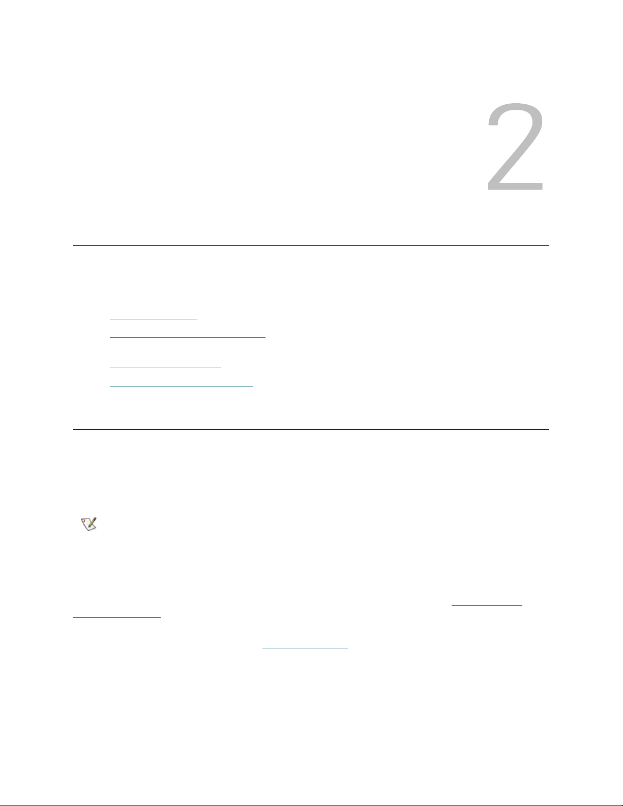
The Scalar DLC provides the connectivity between the library and the customer (client). The connection
type depends on client configuration. See Figure 1
Scalar DLC Reference Guide 3
on page 4.
Page 20
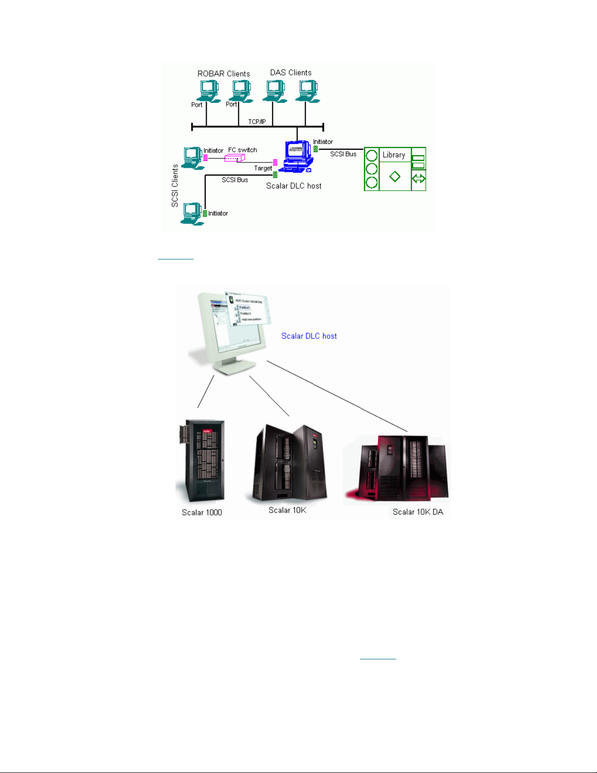
Figure 1 Client Connection
The Scalar tape libraries are connected to the Scalar DLC software host via the SCSI bus or the Fibre
Channel cable. See Figure 2
Figure 2 Physical Libraries connected to the Scalar DLC
.
For each tape library found during Scan SCSI Bus operation, the Scalar DLC software creates an object
called physical library. This object represents all aspects of the real tape device.
Logical Library Concepts
In order for clients to have a flexible way to share common resources (physical library), the Scalar DLC uses
virtual objects called logical libraries to represent the real device for the client. The Management GUI is used
to create and configure these logical libraries. The connection between the logical library and the device is
implemented by means of the partitioning features that are unique to the Scalar DLC software. The
partitioning operation creates a number of element ranges called partitions that are used by the physical
library. These ranges are then assigned to the logical libraries (see Figure 3
who uses a certain logical library can access the correct part of the physical library. This feature is very
useful when clients use a single physical library while the client has access to only a certain resource. The
logical library represents these resources, and the assigned partitions provide a connection between the
logical library and its physical equivalent.
4 Description
on page 5) so that the client
Page 21

This logical library concept is based on a partition containing the continuous range of elements of a single
type (for example, storage) and media domain (for example, DLT). The partitions cannot overlap; however,
a single partition can be assigned to two or more logical libraries. In that case, two logical libraries will have
a shared area, and the clients of the first library can access this area as well as the clients of the second
library.
CAUTION
Note
Figure 3 Partitions and Logical Libraries
Two or more clients either of the same type (for example, DAS-based) or of different types (for example,
DAS-based and ROBAR-based) may use a single logical library. This means that they have rights to use
common resources that are part of this library (cartridges, drives, and so forth). See Figure 4
Sharing the single partition between two or more logical libraries may cause
access problems, so this feature must be used with extreme caution.
The partition cannot contain both storage tower and storage shelf elements, even if they
consist of the identical storage slots (for example, Generic DLT). This means for the
single-media library with a storage tower (for example, Scalar 10K), no less than two
storage partitions should be created in order to cover its storage area completely; the
first partition will cover the tower, and the second will cover the linear storage (storage
shelves).
.
Figure 4 Clients and Logical Libraries
PC System Requirements
The minimum PC system hardware requirements are based on Microsoft PC 2000 System Design Guide
Specifications. The following list summarizes the Scalar DLC system requirements:
Required:
• 800 MHZ or faster Inter Pentium
• 256K L2 Cache
• 256 MB RAM
• Dual matched Hard Drives (10GB or more)
• CD RW
• 3.5" Diskette Drive
TM
or equivalent CPU (minimum 4 free PCI slots in chassis)
Scalar DLC Reference Guide 5
Page 22
• 15" or greater SVGA Display
• NT/2000 compliant SCSI adapter
• Standard keyboard and mouse
• Windows 2000 SP4 or Windows 2003 pre-installed
Optional:
• SCSI target HBA LSI 20860, LSI 8751D, and/or LSI 8951U
• Fibre Channel target HBA QLogic 2200F-33 and/or QLogic 23xxF
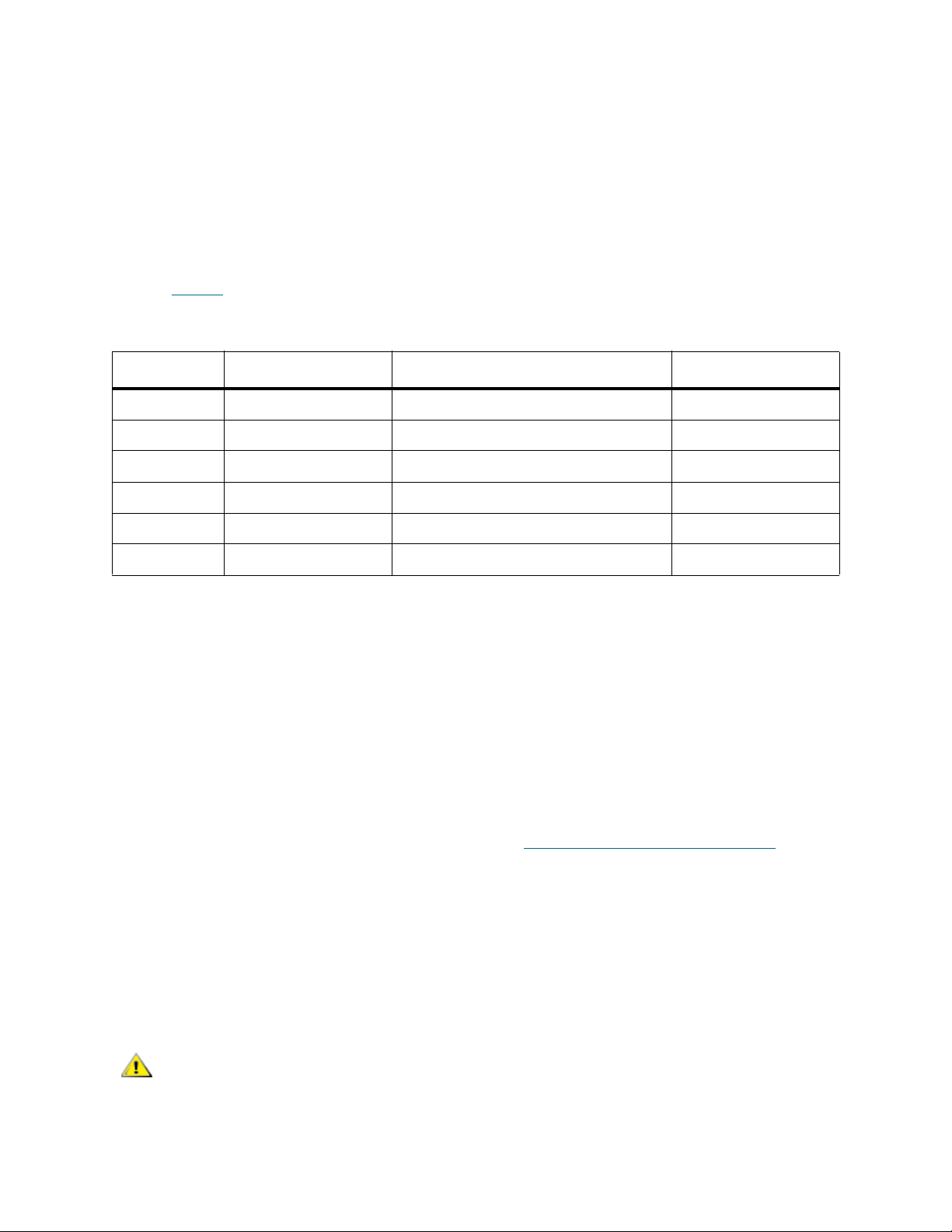
Refer to Table 1
for a description of SCSI and Fibre Channel adapters that can be used in the system.
Table 1 SCSI and Fibre Channel Adapters
Adapter Type Connection (external) Max cable length, m
LSI 20860 SCSI 50-pin high density SE 5
LSI 8751D SCSI 68-pin high density HVD 25
LSI 8951U SCSI 68-pin very high density LVD/SE 12(LVD), 5(SE)
QLA 2200 Fibre Channel SC duplex multi-mode -
QLA 23xx
Local
a. ‘xx’ means 00, 10, 40, and 42. No other models are currently supported.
b. The driver is designed by ADIC to execute the SCSI backup applications right on the Scalar DLC server PC. No SCSI/FC
a
Fibre Channel Small form factor multi-mode optic LC -
b
hardware is required.
SCSI - -
Redundant Solution Requirements
The Scalar DLC Redundant (failover) solution is provided using the Microsoft Cluster service. The user has
a shared disk with the Scalar DLC database and two hosts with the installed components of Scalar DLC
software; for redundancy reasons, one host is online and the other is offline. If an error occurs and the online
host goes offline, the other host turns online immediately, so the customer even does not notice a problem
with the host. The customer engineer can repair the problem host without stopping the Scalar DLC software.
The Scalar DLC Redundant solution is based on Microsoft Cluster service. The special requirements are:
• Two PCs, each meeting the standards described in PC System Requirements
on page 5.
• Microsoft Windows 2000 Advanced Server or Windows 2003 Server installed on each PC.
• Microsoft Cluster Service installed on each PC.
• For each PC, there should be a minimum of two disk controllers. The two disk controllers do not
need to be the same type. For example, using on-board IDE and SCSI is acceptable.
• At least one external (shared) RAID disk. The disk partition should have NTFS formatting.
• RAID adapter (on each PC) to access a shared disk.
The Scalar DLC failover solution in a redundant configuration requires the
CAUTION
Windows 2000 Advanced Server or Windows 2003 Server operating system.
By default, this system is configured without password protection for network
access. So ADIC strongly urges companies using this product to use all
customary procedures to protect Scalar DLC servers from external threats.
6 Description
Page 23
For the details about Scalar DLC Redundant solution, refer to the Scalar DLC Installation Guide.
Tape Library Requirements
The library firmware and hardware requirements are described in this topic.
Operating mode
For the Scalar 1000 library, the following operating modes are supported:
•Native
• EXABYTE compatibility
• Storage Technology compatibility
• EMASS compatibility
For the Scalar 10K library only native mode is supported.
For the Scalar 10K DA (dual-aisle) library:
• Both medium changers (aisles) must run in native mode.
• Both medium changers (aisles) must operate in non-compressed mode.
• At the time of the first configuration, both medium changers (aisles) must be in the online state.
Ready state is not required.
CAUTION
Additionally, for the libraries with towers (Scalar 10K and Scalar 10K DA):
• At the time of the first configuration all towers (if any) must be in the library (online) state.
The Scalar DLC software may not work properly if the tape library operates in
the unsupported mode.
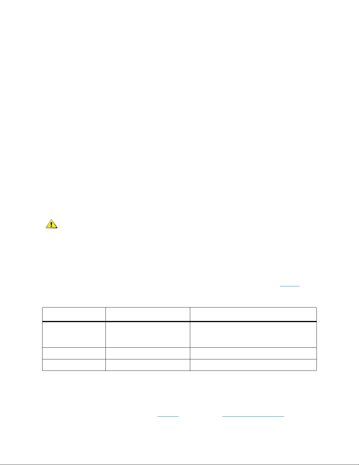
Firmware Version
Make certain the firmware version of each tape library meets the Scalar DLC requirements (Table 2).
Table 2 Required Firmware Version
Tape Library Required Firmware Comment
Scalar 1000 641A or later If the current version is 2.3 or earlier, contact
ATAC. A customer engineer will upgrade the
library with the appropriate firmware version.
Scalar 10K 300A or later
Scalar 10K DA 300A or later (for both robots)
Remote Browser Requirements
The Scalar DLC Management GUI takes advantage of very advanced Java2 features that are not supported
by all browsers. The browser updates can be initiated from the Scalar DLC software splash page by
selecting the Tools and Utilities tab. Refer to Figure 7
Scalar DLC Reference Guide 7
on page 13 and Browser Pre-Installation on page 11.
Page 24

Graphical User Interface
The Scalar DLC software GUI (also called Management GUI) is based on Web browser technology that
guarantees a consistent user interface across all UNIX and Windows platforms. The GUI is available to
users, system administrators, and customer engineers. The Management GUI consists of the following
components:
• Main Menu bar
•GUI Tabs
• Library tab
• Configuration tab
• Events tab
• Service tab
• GUI Log
Each component is covered in detail in the following chapters.
Command Line Interface
The command line interface is supported by the DAS version 3.12 SP2 application. The DAS interface
supports numerous third party software applications.
Additional information about DAS is contained on this CD-ROM in the DAS Administration Guide document.
Service and Maintenance Alerts
The Scalar DLC software monitors all system resources and automatically notifies the ADIC Technical
Assistance Center (ATAC) whenever a service call is required. The information supplied to ATAC includes:
• Error detection
• Event logging and tracing
• Error recovery
Notification is generated by means of applications in the following list:
• GUI Messenger
• Email Home
• Call Home
•SNMP
Each component is covered in detail in the following chapters.
8 Description
Page 25
Configuration
This chapter provides information about logical configuration of the Scalar DLC system for the customer.
Note
The sections are:
• Autostart Installation
• S
calar DLC Management GUI on page 9 contains information on launching the Management GUI.
• Configuration
Local administrator rights are required to install the Scalar DLC software and all required
components.
on page 9 describes the installation order.
on page 16 describes the configuration order.
Autostart Installation
To launch the autostart program, load the CD-ROM in the CD-ROM drive. If the autostart program does not
launch, use the Run option from the Start button on the task bar to execute the autorun.exe program.
For a description of the installation process, refer to Scalar DLC Installation Guide.
Note
The Adobe Acrobat Reader version 4.0 or later is required to view the documentation in
PDF format. Download the most recent version of the software from the Adobe Web site
at http://www.adobe.com
.
Scalar DLC Management GUI
The Scalar DLC Management GUI is started by either the browser-launched applet or the supervisory
desktop application. Before using any of them, determine that the Scalar DLC service is running.
Note
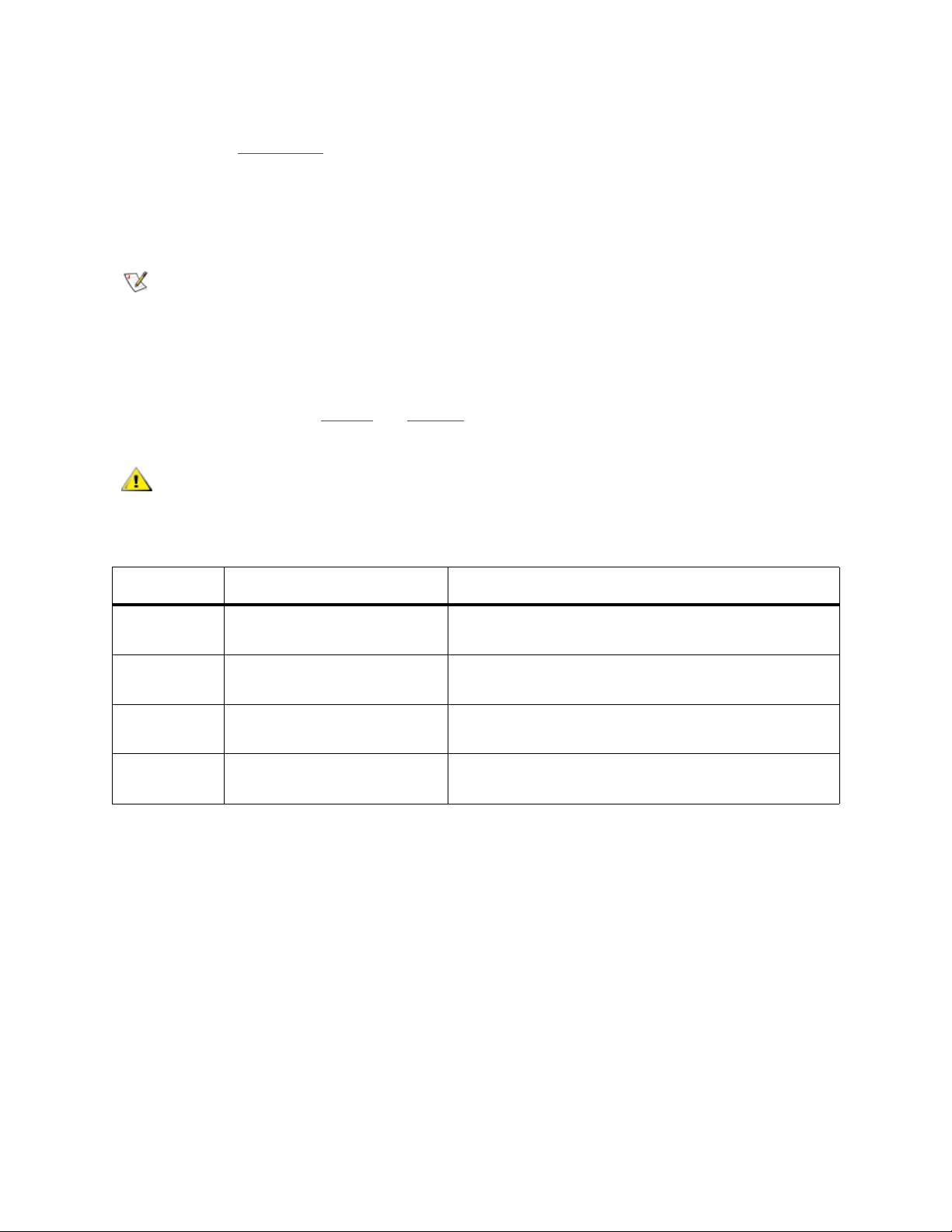
To check the service state (refer to Table 3
the task bar.
Scalar DLC Reference Guide 9
Before starting the Management GUI, verify that the display resolution setting is 800 x
600 pixels or higher and the display color setting is more
on page 10), examine either the Control Panel > Services or
than 256 colors
Page 26

Table 3 Scalar DLC Service State
Task Icon Description
The Scalar DLC supervisor service is stopped (Offline for the Scalar DLC Cluster
solution). Double click the icon to display Figure 5
The Scalar DLC supervisor service is started (Online for the Scalar DLC Cluster
solution). Double click the icon to display Figure 5
The Scalar DLC supervisor service is either starting or stopping (turning online/offline
for the Scalar DLC failover solution).
Figure 5 About Scalar DLC
.
.
The About dialog shows the version of installed Scalar DLC software and its internal components. All Scalar
DLC hot fixes and service packs (if any) are enlisted here, too.
Resizing Windows and Panes
Some Management GUI panes contains data that cannot fit into the standard screen string (for example,
long names of SCSI Adapter objects, or partitions), or a long list of properties that would be useful to see
all in one screen without scrolling. Especially for such cases both the browser-based and application-based
Management GUI allow you to modify the size of the main Scalar DLC window screen as well as to resize
some internal Scalar DLC panes.
Note
Do not reduce the Scalar DLC screen below its original size.
10 Configuration
Page 27
Browser Pre-Installation
Both Netscape Navigator and Internet Explorer browsers must be updated by installing the Java Plugin, as described in Java Plug-In
a remote browser, the update is required before the browser can launch the Scalar DLC software. For a
local browser, the update could be executed manually; but it is best practice to install the browser(s) before
launching the Scalar DLC software installation. The update steps should be executed by either a system
administrator or an expert PC user.
on page 14, to take full advantage of the Scalar DLC Management GUI. For
Note
Start the update procedure by entering the Host name location of the Scalar DLC software server on the
browser address line (for example, http://computer). This establishes a connection with the Scalar DLC
software home page. Refer to Table 4
CAUTION
Table 4 Scalar DLC Home Page Name
Name / ID Value (example only) Explanation
DNS host
name
Cluster name sdlccluster The cluster virtual name (redundant solution only),
DNS address 192.168.1.14 The host network IP address, refer to the Scalar DLC
The Internet Explorer browser is a required component for the Scalar DLC software
installation. If Internet Explorer is not present, the Scalar DLC CD autorun program
installs Internet Explorer as a part of the Scalar DLC Installation process. No preinstallation is required for a complete installation.
and Figure 6 on page 12.
If the Scalar DLC software is installed with SSL support (refer to the Scalar
DLC Installation Guide), always use https:// instead of http://.
computer The host network name used in DNS.
refer to the Scalar DLC Installation Guide.
Installation Guide.
Cluster DNS
address
Scalar DLC Reference Guide 11
192.168.1.10 The virtual cluster IP address (redundant solution
only), refer to the Scalar DLC Installation Guide .
Page 28

Figure 6 ADIC Scalar DLC Home Page
The only required component for the browser update is a Java Plug-in. Click the Launch Java Interface
button when it appears. Refer to Java Plug-In
Selecting the Tools and Utilities tab displays the Tools and Utilities pane (see Figure 7
on page 14 for the description of update process.
on page 13).
12 Configuration
Page 29
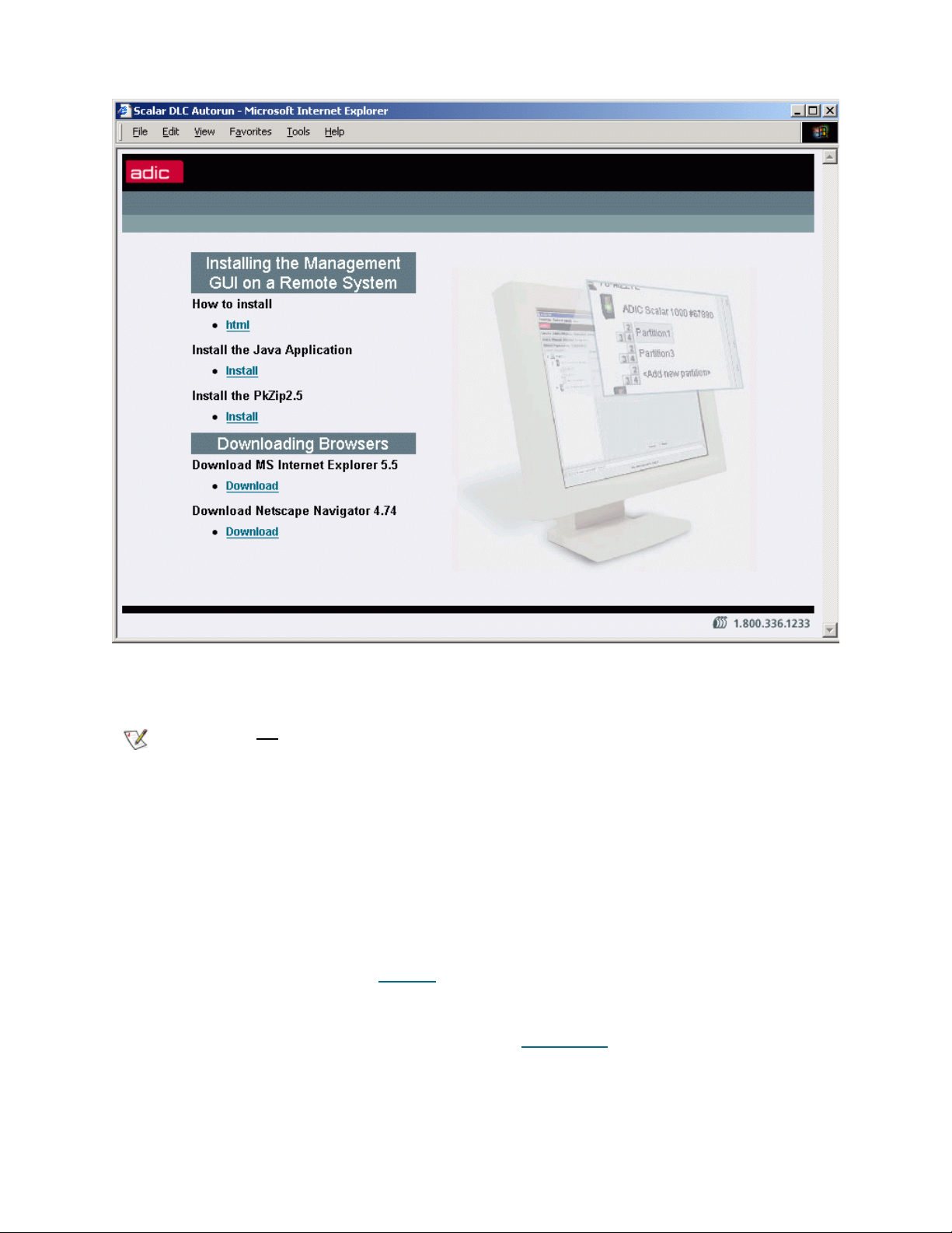
Figure 7 Tools and Utilities Page
The latest required versions of both Netscape Navigator
downloaded from this page.
Note
The Scalar DLC Management GUI that is designed to launch the Scalar DLC software application from a
remote host can be downloaded also. The installation steps of the Scalar DLC Management GUI are
described on this page as well.
Do not download the browser unless your browser version (always shown under Help >
About) is lower than required.
and Internet Explorer browsers can be
Remote Management GUI
The Java-based GUI software is used as a Scalar DLC management tool. It is always installed on the Scalar
DLC server, however the same software can be downloaded from server and launched from a remote host
as well.
From the Tools and Utilities page (see Figure 7
archive containing all files for the remote Management GUI. The “How to install“ link contains the complete
instruction on how to install the package and launch the application.
Also download and install the Java Plug-In, as described in Java Plug-In
) click on “Install Java Application" and download the zip
on page 14.
Scalar DLC Reference Guide 13
Page 30
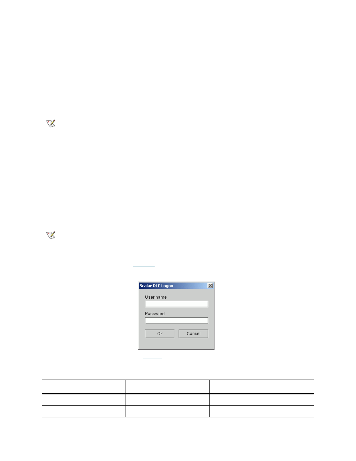
Java Plug-In
When running versions of Netscape Navigator prior to version 4.7, the Scalar DLC Management GUI
requires the Java 2 plug-in 1.4.2_09 release. Installing the plug-in enables direct Java2 applets to run while
using Sun’s JRE (Java Remote Environment). Therefore, the j2re-1_4_2_09-windows-i586-p.exe file must
be executed so that files are added to a specific directory.
Begin the procedure by selecting the hyperlink associated with the Java Plug-in. Save the file to a temporary
directory and then launch it.
The same update procedure should be executed when the Management GUI is used with the remote Scalar
DLC host.
Note
The Java plug-in patch is also required for both the Microsoft Internet Explorer and
Netscape Navigator browsers when the user desires to use the applet-based GUI (refer
to Launch the Management GUI from a Browser
based (Launch the Management GUI as an Application
However, the MS IE browser installs the Java plug-in patch automatically when the
browser-based Management GUI is launched for the first time.
The Netscape Navigator browser needs to be updated manually.
on page 14) rather than application-
on page 15).
Launch the Management GUI from a Browser
Enter the Hostname location of the Scalar DLC server on the browser. This procedure establishes a
connection with the Scalar DLC home page. See Figure 6
Note
When the Scalar DLC home page appears, press the Launch Java Interface button. The Scalar DLC
Logon dialog window appears (see Figure 8
Figure 8 Scalar DLC GUI Logon Dialog
Disk write operations (upload) are not allowed from the browser-launched Scalar DLC
Management GUI due to security restrictions.
).
on page 12.
The default login settings are shown in Table 5
Table 5 Management GUI Default Users
Default user name Default password Access level
admin password Admin (administrator)
atac guardian CE (customer engineer)
14 Configuration
.
Page 31

CAUTION
For the details on user access level and settings refer to Users Tab on page 128.
Because of security reasons it is strongly recommended to change the default
admin and CE passwords after the configuration is complete.
Firewall and Proxy Issues
If the Scalar DLC Management GUI starts but can not connect to the Scalar DLC server, a firewall or proxy
server could be present between the browser and the Scalar DLC server. The remote methods invocation
transport layer normally attempts to open a direct socket connection to the host on the Internet. However,
many intranets have firewalls or proxies that do not allow this procedure.
The Management GUI cannot communicate with the Scalar DLC software server through a firewall if port
1099 is not open. Connections also are easier to make if the browser is not configured to use a proxy. If
necessary, contact the System Administrator to resolve any connectivity issues.
Launch the Management GUI as an Application
From the Windows desktop, launch the Scalar DLC Manager shortcut (Start > Programs > ADIC
Distributed Library Controller > Scalar DLC Manager, or double-click on the Scalar DLC Manager
desktop icon) to enable the host connection window (see Figure 9
The operation can be executed either from local host where the Scalar DLC software is installed or from a
remote host after installing the Management GUI, as described in Remote Management GUI
).
on page 13.
Figure 9 Host Connection Window
Enter the Scalar DLC hostname in the dialog window. Then the Scalar DLC log on dialog appears. See
Figure 8
on page 14.
Note
Disk write operations (upload, download) are allowed from the application-based Scalar
DLC Management GUI.
Scalar DLC Reference Guide 15
Page 32

Configuration
When a user is logged into the Management GUI and no previously configured physical library has been
found, a configuration selection pane opens automatically (see Figure 10
performed, this pane will not appear. Choose the configuration method.
Figure 10 Configuration Window
Either accept the default configuration or select the desired configuration method.
• A
utomatic Configuration on page 17 is recommended for the first-time users that have no
experience in configuring the Scalar DLC system.
); if the configuration has been
• Wizard-based Manual Configuration
knowledge about the configuration of the Scalar DLC.
• Advanced Configuration
experience to perform all configuration manually.
• After the basic configuration is finished, an Additional Configuration
Some client interfaces have certain limitations concerning the names of used objects, for example, some
DAS-based applications do not recognize the mailbox name for Insert command other than Ixx (xx means
any two alphanumeric characters). To avoid such issues, be sure that the objects created and configured
by means of the Scalar DLC Management GUI are named as shown in the Table 6
Note
Table 6 Object name limitations
Object GUI Manager DAS / ACI ROBAR SCSI
Some customer (client) applications do understand the capitalization difference (A and
a), the others do not. ADIC recommends using the common alpha-model (either capitals
or small letters in all object names).
ADIC also strongly does not
(“-”) and other symbols in the object names. Even when the Scalar DLC Management
GUI permits this, the client application may not recognize the appropriate object.
on page 18 is designed for the advanced users that have enough
on page 18 is recommended for the users with basic
on page 23 could be performed.
.
recommend using spaces (“ “), underscores (“_”), hyphens
Host 40 an
Logical library 30 an, a first None (absent) None
16 Configuration
a
, a first 40 an, a first An None
None
(absent)
Page 33

Table 6 Object name limitations (Continued)
Object GUI Manager DAS / ACI ROBAR SCSI
Partition 30 an, a first None (absent) None
(absent)
Client 80 an, a first 80 an, a first 80 an, a first None
Scratch pool 30 an, a first 16 an, a first None
(absent)
Clean pool 30 an, a first 16 an, a first Paa None
Data cartridge, volser 30 an 16 an (6
recommended)
Cleaning cartridge,
volser
Mailbox area, eject
operations
Mailbox area, insert
operations
Drive 40 an, a first 30 an
a. alphanumeric; “a” means “alpha” (A-Z), “n” means “numeric” (0-9).
b. Only for DAS ACI ver. 3.12 and higher.
30 an 16 an (CL + 4 an
recommended)
30 an, a first 3 an, Enn
recommended
30 an, a first 3 an, Inn
recommended
b
(9 an, a first
recommended)
6 an None
CL + 4 an None
Enn None
Inn None
Dnn None
None
None
Automatic Configuration
ADIC recommends the automatic configuration for typical or first time users. Using the automatic
configuration, create a default Scalar DLC configuration for each detected physical library.
The automatic configuration creates the configuration by executing the following procedures:
Step 1 Scans the SCSI bus for physical libraries.
Step 2 Creates partitions for all the physical library elements.
Step 3 Creates a logical library.
Step 4 Assigns all created partitions to the logical library making it a representation of the whole
physical library.
Step 5 For the logical library, creates two identical mailboxes (I01 and E01) that include all the mailbox
slots.
Step 6 Creates a client and assigns it to the logical library.
Note
By default, if the DAS Client support is installed, the created client is the DAS Client; if
not, no client can be created because the SCSI and ROBAR interfaces need certain preconfiguration.
Scalar DLC Reference Guide 17
Page 34

Manual Configuration
For advanced users, the wizard-based configuration automatically scans for libraries and creates physical
library objects by executing the following step-by-step procedures:
Step 1 Scans the SCSI bus for physical libraries.
Step 2 Creates partitions for all the physical library elements.
Step 3 Creates a logical library. The library name can be specified. Also refer to Table 6
Step 4 Assigns the partitions to the logical library. It is possible to select a method of assignment:
single-media library, single-robot library, and the complete library selection are available for the
first-time manual configuration.
Step 5 Creates two identical mailboxes covering all the mailbox slots. The mailbox names can be
specified. Also refer to Table 6
Step 6 Creates a client and assigns it to the logical library. The client name can be specified. Also refer
to Table 6
Note
Refer also to Create Configuration
on page 16.
By default, if the DAS Client support is installed, the created client is the DAS Client; if
not, no client can be created because the SCSI and ROBAR interfaces need certain preconfiguration.
on page 32 for the detailed description of steps.
on page 16.
on page 16.
Advanced Configuration
ADIC recommends this mode for expert or administrator users. In this mode, only the icon associated with
the Scalar DLC software system appears.
To enable all the Management GUI functions, create a working configuration by performing the procedures
in the following sections:
Rescan SCSI Bus
Create the device objects associated with a physical library by using the Rescan SCSI Bus button on the
Configuration > Physical > Controller pane. Refer to P
hysical Tab on page 112.
Create Partitions
Create the partition objects representing desired parts of the Physical Library. That can be done on
Configuration > Physical > Library pane (Add new Partition button). Refer to C
127.
Note
The partition properties can be modified later, even after the partition is assigned to a logical library, via the
Configuration > Physical > Partition pane. Refer to Partition
There should be at least three partitions created for each physical library: storage, I/E,
and drive. Refer to Partition
on page 119 for the details.
on page 119.
reate Partition on page
18 Configuration
Page 35

Create a Logical Library
Create a logical library. That can be done on the Configuration > Logical pane (Add new Library button).
Refer to C
Immediately after creation, the logical library is shown as Invalid. That is correct: Invalid state indicates that
the library does not contain a proper set of partitions.
reate Library on page 107.
Assign Partitions to a Library
Assign the previously created partitions to the new logical library. That can be done through the
Configuration > Logical > Library pane (Assign new Partition button) or Assign Partitions wizard in Main
Menu > Wizards section. Refer to Assign Partition
on page 108 or Assign Partitions on page 38.
Note
The partitions can also be assigned or unassigned at a later time.
There should be at least three partitions assigned to each logical library: storage, I/E,
and drive. The partition can be shared between two or more logical libraries. Refer to
Partition
on page 93 for details.
Create Mailbox
Create one or more mailboxes for a logical library. They will represent its insert/eject areas. This can be
done through the Configuration > Logical > Library pane (Add new Mailbox button). Refer to Create
Mailbox on page 110.
Note
The mailbox name and assigned range of insert/eject slots also can be changed later through the
Configuration > Logical > Mailbox pane (Add/Remove new Slots button). Refer to Assign Slots to
Mailbox on page 100.
Although Management GUI does not have name restrictions for the mailbox name, some
backup applications do have them. Refer to Table 6
on page 16.
Create Client
Create the client object(s) that will represent the customer(s) that will work with the library. Depending on
the interface used, the clients are DAS Clients, SCSI Clients, or ROBAR Clients. Some clients may share
a single logical library.
CAUTION
Setting up the SCSI client to share the logical library with any DAS- or ROBARbased client may cause problems in the work of the client application. Both
DAS and ROBAR interfaces do have the same concept of the cartridge home
position (refer to Home Position
uses only ‘move’ commands.
on page 79) but the SCSI does not because it
DAS
The DAS Client can be created via the Configuration > Clients > DAS pane (Add new Client button).
Refer to Create DAS Client
on page 144.
SCSI
The SCSI Client can be created via the Configuration > Clients > SCSI pane (Add new Client button).
Refer to Create SCSI Client
Scalar DLC Reference Guide 19
on page 155.
Page 36

Note that the Target and LUN objects must be created before via the Configuration > SCSI Target > Port
pane (Add new Target button), and Configuration > SCSI Target > Port > Target pane (Add new LUN
button). Refer to C
reate Target on page 169 and Create LUN on page 170.
Note
It is strongly recommended to create Targets and LUNs as a continuous range of
elements starting from 0 (Target0, Target1, Target2, etc.; LUN 0, LUN1, etc.).
ROBAR
The ROBAR Client can be created via the Configuration > Clients > ROBAR pane (Add new Client
button). Refer to Create ROBAR Client
Note that the ROBAR Port must be configured before the clients can send commands (refer to ROBAR
page 156).
on page 160.
on
Initialize the Logical Library
The library must be initialized for its internal elements and cartridges to be created. It can be done by using
the Inventory button. The same command can be done via the client interface.
Once the initialization process is completed, the library functions are available.
Assign Drives to Cartridges
After the cartridges are created, they may be assigned to the appropriate drives for use by the Generic
mount operation. This will use the assigned drive as the first position in the list of possible mount
destinations. A cartridge can be assigned to one and only one drive, but the drive can be assigned to
multiple cartridges.
The assignment executes (and can be changed later) through the Configuration > Logical > Cartridge
pane (Cartridge properties > Assigned Drive >> Save changes). Refer to Cartridge
on page 94.
Note
This optional feature is not required for SCSI or ROBAR clients, but some DAS clients
do use it.
Inserting New Media
After adding new cartridges to the library through the mailbox always execute Import (insert) operation
(either via client interface or in Management GUI) before starting actually using the new media. The
cartridge that was not inserted can not receive the valid home position (refer to Home Position
and thus a lot of basic functions will be not available.
Note
Assigning a home position via import/insert operation is sometimes the only way to put the cartridge in the
correct logical library.
Example: two libraries (Library1 and Library2) with two different clients (Client1 and Client2) have nonshared storage areas and a shared I/E area. The cartridge that should be accessed by Client2 is put to the
shared mailbox. Client2 (or Admin from GUI in the Library2) must execute the import/insert operation so the
cartridge will go to the storage area of Library2. But if the Client1 launches the import operation first
cartridge will go to the Library1 and become not accessible for the Client2.
The Home Position feature is not used by SCSI clients, but for DAS and ROBAR the
home position (home slot, home address) is a part of their concepse.
on page 79),
, the
20 Configuration
Page 37

Create Scratch Pool
Create the required scratch cartridge pools for a logical library. The scratch pools should contain the data
cartridges ready for writing. That can be done through the Configuration > Logical > Library pane (Add
new Scratch Pool button). Refer to Create Pool
on page 109.
Note
In the same dialog it is possible to add data cartridges to the new pool (Assign/Unassign button). Refer to
Assign Media to Pool
CAUTION
The pool name and assigned cartridge range can be changed later through the Configuration > Logical >
Pool pane. Refer to Pool
existing pool as well as remove them.
Note
Although Management GUI does not have name restrictions for the pool name, some
backup applications do have them. Refer to Table 6
on page 98.
Sharing a single data cartridge between two or more scratch pools is not
allowed.
on page 97. Some DAS and ROBAR clients may also assign cartridges to the
It is possible to create pools before Inventory, but the cartridges will appear in the library
only after it is initialized.
on page 16.
Mark Cleaning Cartridges
After the Inventory is performed, the logical library recognizes all cartridges that it contains. However, the
library cannot say which cartridge is of data type (readable and writable data carrier), and which is of
cleaning type (the tool used for drive cleaning). By default, all cartridges are recognized as data, so it is up
to Admin to mark the correct cartridges as cleaning.
This can be done through the Configuration > Logical > Cartridge pane (Cartridge properties > Type
(data/clean) >> Save changes). Refer to Cartridge
If the cartridge is marked as cleaning by mistake, and in fact it is data, change its type back the same way.
Note
The type of cartridges that are already assigned to the scratch or clean pool cannot be
changed.
on page 94.
Create Clean Pool
Create the required clean pools for a logical library. The clean pools should contain the cleaning cartridges
ready to perform drive cleaning operations. That can be done through the Configuration > Logical >
Library pane (Add new Clean Pool button). Refer to Create Pool
Note
In the same dialog it is possible to add cleaning cartridges to the new pool (Assign/Unassign button). Refer
to Assign Media to Pool
Although Management GUI does not have name restrictions for the pool name, some
backup applications do have them. Refer to Table 6
on page 98.
on page 109.
on page 16.
Scalar DLC Reference Guide 21
Page 38

CAUTION
The pool name and assigned cartridge range can be changed later through the Configuration > Logical >
Pool pane. Refer to Pool
existing pool as well as remove them.
Sharing a single clean cartridge between two or more cleaning pools is
allowed. Watch however the state of that cartridge with extreme caution.
on page 97. Some DAS and ROBAR clients may also assign cartridges to the
Note
The cartridges appear in the library during Inventory, but only Admin can mark the
cartridge as cleaning, as described in Mark Cleaning Cartridges
‘insert cleaning cartridges to pool’ operation can be executed via DAS by DAS Client.
on page 21. Also the
Configure Clean Manager
After the cleaning pools are created and configured, they can be assigned to the appropriate drives for the
drive cleaning operation. Cleaning can be executed either automatically or by client request. This can be
done via the Configuration > Logical > Drive pane (Drive properties > Cleaning). Refer to Drive
104. Specify the correct cleaning time according to the drive type and model. Specify also the cleaning rate
(the number of mounts between cleanings).
on page
Configure Aliasing
Some DAS Clients use old vertions of backup application that cannon correctly recognize the newest
models of media and drives, but must work with such models nevertheless. To fix this issue, Scalar DLC
provides an Aliasing feature.
Using Configuration > Clients > DAS > DAS Client pane > Aliasing (refer to Aliasing
either drive or media (or both) select the alias that the backup application ’understands’ instead of its default
type that the application cannot recognize. Then press Save button to update the client properties. The
Scalar DLC restart is not
Note
This feature is optional and used only by some DAS clients.
required, the client application restart is not required, too.
on page 143) for
Reserve Drives and Cartridges
Some DAS clients may reserve the drives and the cartridges which means no one but the client will access
the appropriate resource.
CAUTION
Enter the appropriate values through the Configuration > Clients > DAS > DAS Client pane (Reserved
Drives > (Select Drive) >> Reserve; Reserved Volsers >> Add Volserrange, Remove Volserrange). Refer
to Drives
reserve operation by using the special commands (allocd, allocv) from the client side.
22 Configuration
on page 138 and Reserve or Define Volsers on page 142. Also the customer may perform a
The drives and cartridges reserved/allocated by Client1 cannot be accessed
by other clients. The allocation must be removed before the other client can
access the reserved resource.
Removing the allocation made by another client is also possible from the
client side by the special command (allocd, allocv) if the client has Supervisor
privileges.
Page 39

Note
This feature is optional and used only by some DAS clients.
Note
Using the Management GUI Admin can execute any operation whether the used
medium and/or drive is reserved or not.
Also Admin can remove the allocation, either through Configuration > Clients > DAS
> DAS Client pane (Reserved Drives >> Specify >> Save changes; Reserved Volsers
>> Add Volserrange, Remove Volserrange), or through Configuration > Logical >
Drive (Drive properties > Owner >> None >> Save changes) and Configuration >
Logical > Cartridge (Cartridge properties > Owner >> None >> Save changes).
Define Drives and Cartridges
Some DAS clients may define the drives they will use and the cartridges they may access.
CAUTION
Define the appropriate values through the Configuration > Clients > DAS > DAS Client pane (Defined
Drives >> Specify >> Save changes; Defined Volsers >> Add Volserrange, Remove Volserrange). Refer to
Define Drives
temporary define operation by using the special command (scop2) from the client side.
on page 140 and Reserve or Define Volsers on page 142. Also the customer may perform a
The drives and cartridges defined by Client1 are in common use, but the
Client1 itself can access only the defined drives and media. ‘None defined’
means the Client1 can use all drives and all media in the library it is assigned
to.
Note
This feature is optional and used only by some DAS clients.
Configure Additional Libraries
Follow the sequence of the previous procedures to configure additional logical libraries.
Note
A re-initialization of the library is necessary if the library properties are changed.
Additional Configuration
The following actions can be performed to make the Scalar DLC more user-friendly.
Create User
By default, the Scalar DLC contains two pre-defined users to work with Management GUI: default
administrator (admin) and default customer engineer (atac). More users can be created.
Step 1 Log on the Management GUI as administrator.
Step 2 Using Users Tab (Configuration > Users tab >> Add new User) create the new user selecting
the user access level and user rights, and specifying login, password, and email settings. Refer
to C
reate User on page 132 and Table 21 on page 129.
Scalar DLC Reference Guide 23
Page 40

Update ATAC Settings
All problem reports (tickets) created by the customer will be sent by default to ATAC on
“watchman@adic.com“. This can be changed if required. Do the following:
Step 1 Log on the Management GUI as administrator. Check the Scalar DLC email notification settings
on Main Menu > Extended Service > Registration Information pane. Refer to R
Information on page 55. The “Email Notification“ field must be checked, and the “SMTP server”
and “port” parameters must contain valid information. Contact the local network administrator
for details.
egistration
Step 2 Open Configuration > Users Tab and select the default CE “atac“ (refer to U
Change the email settings from “watchman@adic.com“ to the required value.
Step 3 Restart the Scalar DLC service for the changes take effect.
ser on page 131).
Configure Email Notifications
To notify the customer via email that the given operation has been performed:
Step 1 Log on the Management GUI as administrator. Create the working configuration. Refer to
A
utomatic Configuration on page 17 or Advanced Configuration on page 18.
Step 2 Using the Rule Wizard (Main Menu > Wizards > Create Rule) create the rule that will react
when a certain event occurs in the system and will send a notification about this event to a
certain email address. Refer to Create Rule
Note
Step 3 After creating the rule, go to Events > Rules Tab and ensure that the rule is correct and active.
The Scalar DLC database contains the email addresses of all users (refer to User on
page 131) and the email addresses that were entered manually during rule creation (see
Figure 37
in this list, it can be selected during the rule creation process; if not, it can be entered
manually and will be thereby added to the database.
Refer to R
on page 53 and Figure 38 on page 53). If the required email address is present
ules Tab on page 179.
on page 45.
Step 4 Check the Scalar DLC email notification settings on Main Menu > Extended Service >
Registration Information pane. Refer to R
Notification“ field must be checked
valid information. Contact the local network administrator for the details.
Step 5 Restart the Scalar DLC service for the changes to take effect.
The received email shall look as follows:
Packet Type: <Automatically Open Ticket>
Packet Revision Level: <2.6 build 3>
Current Time: <Friday, Nov 19, 2005 04:07:08 PM>
Scalar DLC s/n: <DLC12345>
Packet Number: <{AFC3A8D1-EE87-4C45-913B-A949907E1D63}.92.3>
Site ID: {}
Source: <Automated: DLC12345>
Total call Time: <N/A>
# of times packet was sent: <0>
===================================
24 Configuration
, and the “SMTP server” and “port” parameters must contain
egistration Information on page 55. The “Email
Page 41

Site ID: {}
Caller Name: <Automated: DLC12345>
Caller Phone: <none>
Modem Phone: {}
Call-In Enabled: {yes}
Company Name: {Scalar DLC Installation}
Call Type: {not available}
Call Subtype: {not available}
Device: {not available}
System Serial Number: {ADIC Scalar 1000 #111111111}
Item Serial Number: {not available}
Service Action Code: 80
Service Action Code Modifier: <12345678>
Service Action Code Description: <Failures detected in the X-axis Servo
system.>
Priority: <not available>
Description: <General hardware problem>
Configuration Table: <not available>
Physical Library Name <ADIC Scalar 1000 #11111>
Note
Some fields may be empty, or contain <none> or <not available> which is correct
especially in case of the automatically created/opened tickets with the appropriate email
notification.
Installing New Slots
When the new slot (for example, drive) is installed in the physical library, perform the following actions so
that the Scalar DLC logical libraries have the correct reflection of the current hardware.
Step 1 Install the slot(s), make all proper connections according to the library Operator Guide.
Step 2 Execute Teach command from the robot Operator Panel. After the command is finished (that
may take some time) the slot will appear in appropriate range of the physical library.
Step 3 For each newly installed slot, verify the partition settings.
a. If the new slot has appeared in the unpartitioned space, then everything is correct and it can be
used as any other slot after adding to the appropriate partition.
b. If the new slot has appeared in the partitioned space and its type and media domain match the
existing partition properties, it is accessible for every client that can access the appropriate
partition.
c. If the new slot has appeared in the partitioned space and its type and media domain do not
match the existing partition properties (for example, SDLT 220 Drive appeared in the middle of
IBM LTO Drive partition), the newly installed slot becomes incompatible, and the Management
GUI shows it (see Table 16
Admin must manually correct the situation by changing the range of the existing partition until
it will not cover the new (not compatible) slot. Then another partition must be manually created
and assigned to the appropriate logical libraries. Perform a complete inventory after all
assignments are done.
on page 67 and Table 15 on page 66).
Scalar DLC Reference Guide 25
Page 42

Operating the Tape Library Doors
It is possible to stand up right before the tape library device and manipulate its doors when the Scalar DLC
is in work. Moreover, it is required sometimes.
The Scalar DLC will reflect as much as it could, but some operations (especially executed by the clients who
use backup applications and do not monitor the resource before launching the command) are to be failed
when the doors are opened.
Front Door
When the front door is in open state, the Scalar DLC resources can be described as follows:
Element State, single-aisle library State, dual-aisle library
Robot Offline Offline
Physical library Offline Online
Partition, drive, storage, mailbox Offline Online / offline
Logical library Offline Online / offline
a. That is, online if the second front door is closed and the second robot is online.
b. Depends on the state of the robot where the partition is physically located on, whether it is offline or online.
c. Depends on the partitions the library contain, whether all of them are offline or some are online.
a
b
c
When the front door of Robot1 on the dual-aisle system is opened, the Robot2 may still perform operations
that do not use resources managed by Robot1 (for example, mount from <Robot2 storage> to <Robot2
drive> shall pass). If the customer-requested resource is in Robot1 control, the Scalar DLC marks the
resource as ‘not accessible’ and the operation shall fail.
BE VERY CAREFUL WHEN OPENING THE FRONT DOOR. THE AISLE
WARNING
MECHANICS WILL GO OFFLINE WHEN THE DOOR IS OPENED BUT IT TAKES
TIME.
After the front door is closed the robot must be manually turned online from the operator panel. Then the
robot starts the complete inventory operation to check whether the new elements are installed, and if so,
map them correctly.
I/E Station Door
When the door of insert/eject station is opened the Scalar DLC marks the elements of this station as ‘not
accessible’. Any operation that involves the non-accessible resource (for example, move to the nonaccessible mailbox slot) will fail. The other operations (for example, dismount, clean, move to the mailbox
slot of the other insert/eject station) shall pass.
Closing the insert/eject door starts the partinventory (partial inventory) of the appropriate insert/eject
station to check whether the new cartridges were put in the library or the cartrigdes ejected to the mailbox
were removed.
26 Configuration
Page 43

Managing the Database
The separate Database Tool (refer to Database Tool on page 206) is used for every operation that is
allowed with the Scalar DLC database. The tool is launched from Start > Programs > ADIC Distributed
Library Controller > Scalar DLC DB Tool (or right-click on Scalar DLC tray icon and then Tools > Scalar
DLC DB Tool).
Set Up Database Backup Mode
Step 1 Launch DB tool, log in and open Extended mode tab (refer to Extended Mode on page 209).
Step 2 Check Full recovery mode box if the database is to be backed-up with full information. Uncheck
the box if only the database itself is to be backed-up.
Step 3 Press Apply button to apply settings, them Exit to close DB tool.
Schedule Database Backup
Step 1 Launch DB tool, log in and open Backup tab (refer to Database Backup on page 207).
Step 2 Set up the Backup destination in automatic backup. Check the Time-generated file names box
if the backup files are to be named according the backup date.
Step 3 Set up the Backup schedule and then check Enable schedule box.
Step 4 Press Apply button to apply settings, them Exit to close DB tool.
Schedule Transaction Logs Backup
Step 1 Launch DB tool, log in and open Extended mode tab (refer to Extended Mode on page 209).
Step 2 Set up the Destination in automatic transaction logs backup.
Step 3 Set up the Schedule and then check Enable schedule box.
Step 4 Press Apply button to apply settings, them Exit to close DB tool.
Backup Database Manually
Step 1 Launch DB tool, log in and open Backup tab (refer to Database Backup on page 207).
Step 2 Set up the Backup destination in Manual backup.
Step 3 Press Execute button to backup the database to a file, them Exit to close DB tool.
Schedule Database Compact
Step 1 Launch DB tool, log in and open Compact tab (refer to Database Compact on page 212).
Step 2 Set up the Compact schedule and then check Enable schedule box.
Step 3 Press Apply button to apply settings, them Exit to close DB tool.
Scalar DLC Reference Guide 27
Page 44

Compact Database Manually
Step 1 Launch DB tool, log in and open Compact tab (refer to Database Compact on page 212).
Step 2 Press Execute button to compact the database, them Exit to close DB tool.
Restore Database from Backup
Step 1 Launch DB tool, log in and open Restore tab (refer to Database Restore on page 214).
Step 2 Stop the Scalar DLC software (bring offline for a failover solution).
Step 3 Select Database to restore from a regular backup, then select a backup from a database
backup list.
Step 4 To restore the database with transaction logs, check also Restore with logs box and select the
transaction log.
Step 5 Press Restore button to restore the database, them Exit to close DB tool.
Step 6 Start/bring online Scalar DLC again.
Restore Database from File
Step 1 Launch DB tool, log in and open Restore tab (refer to Database Restore on page 214).
Step 2 Stop the Scalar DLC software (bring offline for a failover solution).
Step 3 Select From device to restore from a file, then select a device name (file) to restore the
database from.
Step 4 Change the names for a database file and transaction log file if the default values are not good
enough.
Step 5 Press Restore button to restore the database, them Exit to close DB tool.
Step 6 Start/bring online Scalar DLC again.
Archive Database
Step 1 Launch DB tool, log in and open Save tab (refer to Database Save on page 216).
Step 2 Set up the Destination.
Step 3 Press Save button to save the database archive to a file, them Exit to close DB tool.
28 Configuration
Page 45

Management GUI
This chapter describes the structure of Scalar DLC Management GUI and provides a brief description of its
functionality.
The Management GUI screen is divided into three areas (see Figure 11
• The upper portion of the screen contains the Main Menu bar. Refer to Main Menu Bar
• The center portion of the screen contains the library related menus, configuration and service tabs,
and more. Refer to GUI Tabs
• The lower portion of the screen holds the GUI Log. Refer to GUI Log
on page 61.
on page 30).
on page 30.
on page 69.
Scalar DLC Reference Guide 29
Page 46

Figure 11 Management GUI
Main Menu Bar
The Main Menu Bar contains five sections. See Figure 12 on page 30. The sections are:
• Screen Refresh Icon. Forces the Management GUI screen to refresh. Refer to Screen Refresh Icon
on page 31.
• Connection. Contains the user connection options. Refer to C
• Wizards. Contains the wizard-based engines for configuring logical libraries, assigning partitions,
creating tickets, and creating rules. Refer to Wizards
• Extended Service. Contains some service panes like registration information, online log viewer etc.
Refer to E
• Help. Contains Management GUI help panes. Refer to H
Figure 12 Main Menu Bar
xtended Service on page 54.
on page 32.
onnection on page 31.
elp on page 60.
30 Management GUI
Page 47
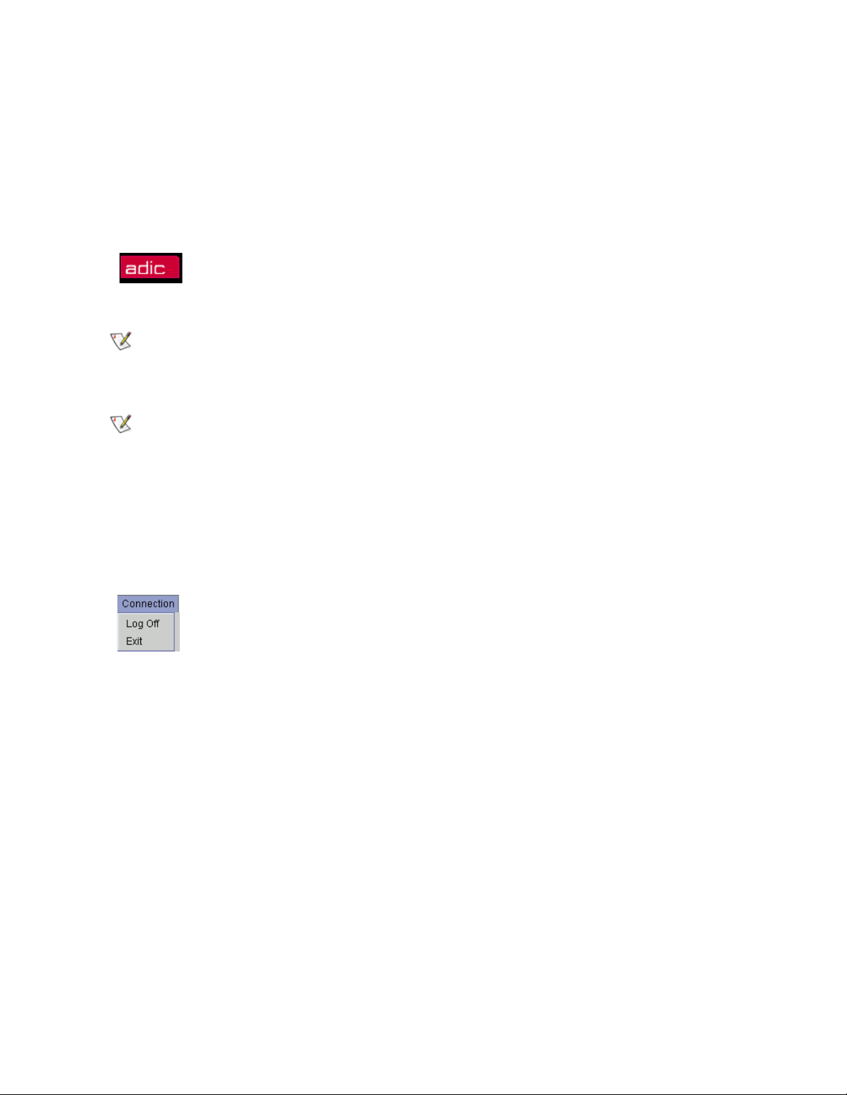
Screen Refresh Icon
The broad black bar containing the red ADIC logo is a screen refresh icon. It also contains the user-to-host
connection status (as at the example picture, User admin connected to computer, where admin is the user
name and computer is either the Scalar DLC host name or the Scalar DLC cluster name). This button
forces the Management GUI screen to refresh.
Icon Description
Refresh the Management GUI screen.
The black bar itself acts as the refresh button, too.
Note
Note
Depending on the PC performance and the current Scalar DLC configuration, the refresh
may take up to several minutes.
Some update (for example, library statistic) is not performed by the global refresh but
requires special refresh operarion initiated by an appropriate button.
Connection
This section contains the basic Log off and Exit operations.
Options Name Description
Log Off Log off the Management GUI. A new log on dialog appears.
Exit Close and exit the current applet or application and log off the user.
Scalar DLC Reference Guide 31
Page 48

Wizards
The Wizards section contains the wizard-based engines used to create some Scalar DLC internal elements.
It contains the following options:
Options Wizard Description Access
Create
Configuration
Assign
Partitions
Create Ticket Creates the report issue (ticket) which will be
Create Rule Creates the rule that will notify the specified
All wizards contain the same operational buttons (Table 7
Table 7 Wizard Buttons
Name Icon Operation Description
First Click Return to the first dialog (disabled at the first wizard dialog).
Creates the logical library according to the
user-specified values (library name, assigned
client, etc.). Refer to Create Configuration
page 32.
Either assigns a number of partitions to the
logical library, or removes a number of
partitions from the logical library (without
deleting these partitions physically). Refer to
Assign Partitions
immediately sent to the ADIC Technical
Support Center (ATAC). Refer to Create
Ticket on page 40.
user or person that a certain event has been
occurred. Refer to Create Rule
on page 38.
on page 45.
).
on
Admin only
Admin only
All users
Admin only
Previous Click Return to the previous dialog (disabled at the first wizard
dialog).
Next Click Go to the next wizard dialog.
Create/Finish Click Create (only at the last dialog).
Cancel/Exit Click Cancel creation or exit wizard after successful creation.
Create Configuration
The Configuration wizard: creates a logical library that covers all the parts of the selected physical library;
creates two identical mailboxes (I01 and E01) that cover the entire insert/eject area; and assigns a client to
the created library. The wizard automatically creates the required partitions in the ranges of a physical
library and assigns them to the logical library.
32 Management GUI
Page 49

Selecting the Create Configuration option activates the Configuration wizard. The first dialog is Physical
Library selection. See figure below.
Figure 13 Select Physical Library
Name Operation Description
Select Physical
Library
Select Select the physical library from the combo box. The created
library will be based on the selected device.
The next dialog is Logical Library Selection. See figure below.
Figure 14 Select Logical Library
Accept the default name or enter the desired name. ADIC recommends accepting the default name while
being sure not to duplicate the name of existing libraries.
Name Operation Description
Name of new Logical Library Enter Enter the new logical library name.
Scalar DLC Reference Guide 33
Page 50

The next dialog is Configuration Method selection. See figure below.
Figure 15 Select Configuration Method
Name Operation Description
Define the
method of
creating a
Logical
Library
Select by Media
Type
analogously
to existing
library
from unused
elements
from
elements by
R1
from
elements by
R2
from
elements by
R1 & R2
Create the single-media library.
The Next button will show the Figure 16
on page 35
with the media selection dialog.
Create the copy of already created library.
Enabled only when there is at least one logical library
already.
The Next button will show the Figure 17
on page 35
with the prototype selection dialog.
Create the library from the elements that are currently
not
assigned to any other logical library.
Enabled only when there is at least one not assigned
element in a physical library.
Create the library from the elements available for the
Robot1.
Create the library from the elements available for the
Robot2.
Enabled only for the dual-aisle physical library.
Create the library from the elements available for both
Robot1 and Robot2
Enabled only for the dual-aisle physical library.
34 Management GUI
Page 51

Figure 16 Select Media
Name Operation Description
Detect media type Select Select the media type for the single-media library. Refer to
Media Type
s on page 246.
Figure 17 Select Library Prototype
Name Operation Description
Select logical library Select Select the existing logical library which will be the prototype for
the new library.
Scalar DLC Reference Guide 35
Page 52

The next dialog is Mailbox selection.
Figure 18 Select Mailbox
Accept the default names or enter the desired names. ADIC recommends accepting the default names.
Name Operation Description
Name of new Maibox Enter Enter the name of the new mailbox (E01 for export).
Name of new Maibox Enter Enter the name of the new mailbox (I01 for import).
The next dialog is Client selection. See figure below.
Figure 19 Select Client
36 Management GUI
Page 53

Name Operation Description
Select the
type of new
Client
Select DAS Client creates the DAS client with all parameters by default.
Always available if the DAS Client support is installed.
SCSI Client creates the SCSI Client assigned to the first free LUN of
the first existing Target. Available only after the SCSI is configured (at
least one target is created and at least one LUN is free). Refer to
C
reate Target on page 169 and Create LUN on page 170.
ROBAR Client selects the ROBAR Client. Available only after the
ROBAR interface is configured (non-zero port is specified). Refer to
Name of new
ROBAR
Enter Enter the name of the new client.
on page 156.
Client
Accept the default name or enter the desired name. ADIC recommends accepting the default name while
being sure not to duplicate an existing client name.
The next dialog is Configuration Summary. See figure below.
Figure 20 Configuration Summary
Name Operation Description
Summary Supplied Be sure that the data entered from the previous dialogs is correct.
Scalar DLC Reference Guide 37
Page 54

The final configuration dialog then appears.
Figure 21 Configuration Complete
Name Operation Description
Operation list Supplied The list of operations executed by configuration wizard.
Assign Partitions
The Partition Assignment wizard assigns the partition(s) to the logical library or executes the backward
operation. The logical library and the partitions to assign must be created before launching the wizard.
Selecting the Assign Partitions option activates the Partition Assignment wizard.
There are two types of Partition Assignment wizard first screens. Figure below appears when the selected
logical library contains at least one partition.
Figure 22 Partitions Contained
38 Management GUI
Page 55

Figure below appears when the selected logical library contains no partitions.
Figure 23 Partitions Not Contained
Name Operation Description
Select Logical Library Select The logical library to assign/unassign partition(s).
Select Physical
Library
Supplied The physical library whose partition(s) are already assigned to
the selected logical library.
Select The physical library whose partition(s) should be assigned to
the selected logical library.
The next wizard screen shows the assign/unassign dialog.
Figure 24 Partition List
Name Operation Description
Library name Supplied The logical library to assign/unassign partition(s).
Partition(s) Check The checked partitions are, or should be, assigned to the logical
library. The not checked partitions currently are not assigned to the
library or should be unassigned from it. The changes are marked with
asterisks.
Scalar DLC Reference Guide 39
Page 56

Name Operation Description
Partition
properties
Figure 25 Partitions Summary
Supplied Name Partition name.
Class Partition class (Storage, I/E, Drive). See Table 13
page 65.
Type Partition media type. Refer to S
247, Mailbox Type
page 249.
Start Starting address in the range of the partition elements.
End Ending address in the range of the partition elements.
s on page 248, or Drive Types on
torage Types on page
on
Name Operation Description
Summary Supplied Shows the summary for the assign/unassign partition(s)
Create Ticket
Ticket is a brief report of the problem encountered by the user that should be solved by ADIC Technical
Assistance Center (ATAC). After the ticket that describes the problem is created, the email notification is
sent to ATAC. The ATAC solution will allow the CE (customer engineer) to begin working toward a solution
of the problem. Information supplied to the ticket becomes a part of the ATAC Calls pane. Refer to A
Calls Tab on page 189.
Selecting the Create Ticket option activates the Ticket wizard.
TAC
40 Management GUI
Page 57

Figure 26 Ticket Registration
Name Operation Description
Enter your name Enter The issue originator name.
Enter your phone
Enter The issue originator contact phone number.
number
System Serial
Number
Supplied The system serial number (taken directly from the Scalar DLC
Database).
The Ticket Priority and Description dialog is the next step in the wizard process. A priority is selected, and
a description of the problem is entered.
Figure 27 Ticket Priority and Description
Scalar DLC Reference Guide 41
Page 58

Name Operation Description
Select a
priority for
the ticket
Select Critical means the problem must be solved immediately. Highest
priority.
Urgent means that solving the problem is very important but not critical.
High priority.
Major means that the problem should be solved. Medium priority.
Minor means that the problem should be solved. Low priority.
Enhancement means that the problem should be solved. Lowest priority
Enter a brief
description of
Enter
A description of the problem.
the problem
The Ticket Category dialog is used to select a category for the problem. The frequency of the problem is
established.
Figure 28 Ticket Category
Name Operation Description
Select a
Select Do not know means the problem category is unknown.
problem
category that
describes the
problem
Operator means the problem source is an operator error.
Hardware means the problem source is a hardware error.
Firmware means the problem source is a software error.
Service call means the user has asked for service help.
Configuration means the problem source is a wrong system
configuration.
Statistical means the problem source is statistical data.
42 Management GUI
Page 59

Name Operation Description
Did the
problem
occur once or
repeatedly?
Select Do not know means the problem frequency is unknown.
Temporary means the problem occurred once and was not reproduced.
Permanent means the problem appeared several times.
The Ticket Device, Library, and Client dialog selects the problematic device, details the location of the
logical library that contains the device, and identifies the associated client.
Figure 29 Ticket Device, Library, and Client
Name Operation Description
Select the device where the
problem is
Select the logical library
where the device is located
Is the problem related to a
specific client
Select Select the device from the combo box if the problem is
somewhere in the device.
Select Select the logical library from the combo box if the
problem is with the logical library.
Select Select the client from the combo box if the problem
related with a client.
Scalar DLC Reference Guide 43
Page 60

The Ticket Service Code dialog establishes the service code associated with the problem.
Figure 30 Ticket Service Code
Name Operation Description
Select the
Service Code
for the
problem
Select Do not know means the code is unknown.
Unscheduled Repair means an unexpected repair is required.
Scheduled Repair means a pre-arranged time has been allocated for
the repair.
Information Call means information is sent to ATAC.
Customer Resp. means the problem is caused or belongs to the
customer.
Preventive Maint. means routine preventive maintenance is scheduled.
Installation means the ticket is generated to notify ATAC about the
installation of the system.
De-Installation means the ticket is generated to notify ATAC about a
system de-installation.
EC/Field Bill means a service call is the result of an EC/Field build
installation.
Feature Code Change means a new feature or function is added to the
system.
44 Management GUI
Page 61

The Ticket Summary dialog contains selected information from the previous dialogs. The wizard assembles
the data and requires a verification.
Figure 31 Ticket Summary
Name Operation Description
Summary Supplied Be sure that the data entered from the previous dialogs is correct.
Note
The Create button is disabled while the ticket is in the creation process. During this
period, the data is being integrated into the ATAC Calls pane.
Create Rule
The Scalar DLC software contains rules for monitoring system events either by sending notification via email
or directly to the Management GUI. In addition, system rules are generated by the Scalar DLC software
itself. The user can define rules that will operate in a similar manner. See Table 8
of the events and matching rules configuration.
Note
Table 8 Event Specification
Event Event Group Specific Event
Start
supervisor
In the table that follows, (Any) means selection “Any,” (None) means selection “None”,
(#) means exact selection (for example, Library1, or Client2).
For the details on Error code, if any, refer to Error Codes
Statistical SDLC supervisor has
been started
Error
code
0 None None None
Physical
Library
for the detailed description
on page 251.
Logical
Library
Client
Stop
supervisor
Scalar DLC Reference Guide 45
Statistical SDLC supervisor has
been stopped
0 None None None
Page 62

Table 8 Event Specification (Continued)
Event Event Group Specific Event
License
expiration
Statistical License is to expire in a
few days
warning
Physical
library is
Statistical New physical library is
created
created
Physical
library is
Statistical Physical library has
been deleted
deleted
Physical
library state
Statistical The library state has
changed
changed
Logical
library state
Statistical The library state has
changed
changed
Library Tape
Alert
Statistical Message about Drive
Tape Alert Flag
Error
code
Physical
Library
Logical
Library
Client
0 None None None
0 None None None
0 None None None
0 Any None Any
#
0 None # None
0 Any None Any
#
Drive Tape
Alert
Front door
closed
Inventory
(GUI)
Inventory
(auto)
Inventory
(common)
Move
cartridge
(common)
Move
cartridge
(client)
Move
cartridge
(GUI)
Statistical Message about Drive
Tape Alert Flag
Statistical Library door closed.
Context defined below.
Statistical Library elements have
been inventoried
Statistical Library elements have
been inventoried
Statistical Library elements have
been inventoried
Statistical A cartridge has been
successfully moved
Statistical A cartridge has been
successfully moved
Statistical A cartridge has been
successfully moved
0 # None Any
0 # None Any
0 None # None
0 # None Any
0##Any
0None##
0None#Any
#
0None#Any
Physical
element state
Statistical Library elements
changed its state
0##Any
changed
46 Management GUI
Page 63

Table 8 Event Specification (Continued)
Event Event Group Specific Event
Logical
element state
Statistical Library elements
changed its state
changed
New
firmware
loaded
New
firmware
loaded
Drive
cleaning
Statistical New firmware has
been loaded to
physical library
Statistical New firmware has
been loaded to
physical library
Statistical Message from Clean
Manager about drive
cleaning
Clean pool
requires
service
Element(s)
allocated by
client
Statistical A clean’s pool
condition has become
critical
Statistical Logical library element
has changed its
allocation state
Error
code
Physical
Library
Logical
Library
Client
0 None # None
0 # None Any
0None#Any
0None##
0 None # None
0None##
Cluster node
changed
Hardware
error:
generic, and
so forth
Hardware
error:
accessor
cannot pick a
cartridge
Hardware
error:
accessor
cannot put a
cartridge
Hardware
error:
destination
full
Hardware
error: source
empty
Statistical Cluster node has been
changed
Hardware An erroneous situation
has been encountered
Hardware An erroneous situation
has been encountered
Hardware An erroneous situation
has been encountered
Hardware An erroneous situation
has been encountered
Hardware An erroneous situation
has been encountered
0 None None Any
217 Any Any Any
#
216 Any Any Any
#
215 Any Any Any
#
223 Any Any Any
#
222 Any Any Any
#
Scalar DLC Reference Guide 47
Page 64

Table 8 Event Specification (Continued)
Event Event Group Specific Event
Hardware
error:
Hardware An erroneous situation
has been encountered
accessor
cannot move
Hardware
error:
Hardware An erroneous situation
has been encountered
common
General
failure:
General An erroneous situation
has been encountered
common
Not ready:
common
Not ready:
device is
General An erroneous situation
has been encountered
General An erroneous situation
has been encountered
becoming
ready
Illegal
request:
General An erroneous situation
has been encountered
destination
full
Error
code
Physical
Library
Logical
Library
Client
360 Any Any Any
#
220 Any Any Any
#
217 Any Any Any
##
205 Any Any Any
#
248 Any Any Any
#
223 Any Any Any
##
Illegal
request:
source empty
Illegal
request:
destination is
accessor
Illegal
request:
invalid CDB
field
Illegal
request: I/E
station door
open
Abort:
command
aborted
General
failure
(Scalar 1000)
General An erroneous situation
has been encountered
General An erroneous situation
has been encountered
General An erroneous situation
has been encountered
General An erroneous situation
has been encountered
General An erroneous situation
has been encountered
General An erroneous situation
has been encountered
222 Any Any Any
##
358 Any Any Any
##
363 Any Any Any
##
368 Any Any Any
##
376 Any Any Any
#
247 Any Any Any
#
48 Management GUI
Page 65

Table 8 Event Specification (Continued)
Event Event Group Specific Event
General
failure
(Scalar 1000)
General
failure
(Scalar 1000)
General
failure
(Scalar 1000)
General
failure
(Scalar 1000)
General
failure
(Scalar 1000)
Internal error Internal An erroneous situation
License
expired
General An erroneous situation
has been encountered
General An erroneous situation
has been encountered
General An erroneous situation
has been encountered
General An erroneous situation
has been encountered
General An erroneous situation
has been encountered
has been encountered
Configuration License has been
expired
Error
code
212 Any Any Any
354 Any Any Any
221 Any Any Any
355 Any Any Any
226 Any Any Any
0 Any Any Any
0 None None #
Physical
Library
Logical
Library
##
##
##
##
##
Client
Configuration
changed
Manually
created ticket
Automatic
created ticket
Ticket in
work
Close ticket Ticket Close ticket 0 None None Any
Note
Configuration Configuration changed 0 None None #
Ticket Open ticket (manually) 0 None None Any
Ticket Open ticket (auto) 0 None None Any
Ticket Continue ticket 0 None None Any
An incorrect rule cannot be created. Only the selections matching the selected event
group, event, and so forth, are enabled in the Rule wizard.
Scalar DLC Reference Guide 49
Page 66

Selecting the Create Rule option opens the Rule Name dialog. Specify the rule name here.
Figure 32 Rule Name
Entry Operation Description
Enter the name for
the new rule
Enter The rule name. ADIC recommends using names describing
the meaning of the rule.
The Rule Event dialog continues the wizard process. The event group and specific event are specified here.
Figure 33 Rule Event
Entry Operation Description
Event group Select Event group selection. See Table 8
Notification of events Select Event selection. See Table 8
50 Management GUI
on page 45.
on page 45
Page 67

The Rule Event dialog continues the wizard process The device, library, and client must be specified here.
Figure 34 Rule Event Location
Entry Operation Description
Device Select Device (Physical library) selection. See Table 8
Library Select Logical library selection. See Table 8
Client Select Client selection. See Table 8
Specific error
situation
The Rule Notification Sent dialog continues the wizard process. The way to send notification is specified
here.
Figure 35 Rule Notification Sent Dialog
Enter An error code listing. Refer to Error Codes
page 45.
on page 45.
on page 45.
on page 45.
on page 251 and Table 8 on
Note
Scalar DLC Reference Guide 51
Although there exist some predefined rules that send notification via SNMP, the usercreated rules other than predefined cannot deliver SNMP notification because of
interface properties.
Page 68

Entry Operation Description
Deliver notification by Select EMAIL sends notification via email.
GUI sends a notification to the Management GUI.
Generate ticket by
acknowledge
Check Enable/disable a service ticket generation request
(enable only when GUI selected).
Next Click If EMAIL is selected, the Rule Email Destination dialog
appears. See Figure 37
on page 53.
If GUI is selected, the Rule Notification Receiver
dialog appears. See Figure 36
.
The Notification Receiver dialog pane identifies the user who receives the notification.
Figure 36 Rule Notification Receiver
Entry Operation Description
Notification receiver Select A selection from the user list.
Next Click Go to the next wizard dialog (Summary).
52 Management GUI
Page 69

The Rule Email Destination dialog identifies the user who receives the notification via email.
Figure 37 Rule Email Destination
Entry Operation Description
Choose/
create
destination
Select A selection from the current list of email destinations. The default
entries in the list that cannot be removed are atac (default CE) and the
“contact person,” as shown in Figure 40
on page 55.
Delete Click Delete the entry from the list.
Add Click Add an entry to the list. See Figure 38
Choose
template
Select Choose a selection from the combo box. Only valid template (matched
the rule) could be selected.
.
Next Click Go to the next wizard dialog (Summary).
The Rule Email dialog identifies the user who should receive the notification.
Figure 38 Rule Email
Scalar DLC Reference Guide 53
Page 70

Entry Operation Description
Name Enter Email sender name.
To Enter Email recipient address.
From Enter Email sender address.
Host To Enter Recipient email server.
Host From Enter Sender email server.
Port Enter Sender email port (the default is shown).
The last Rule wizard dialog displays the Rule Summary.
Figure 39 Rule Summary
Entry Operation Description
Summary Supplied Be sure that the data entered from the previous dialogs is correct.
Extended Service
This section contains the extended service operations.
Operations Name Description
Registration
Information
Connect to RMU RMU connection window. Refer to Connect to RMU
View Log Online log viewer window. Refer to View Log
Scalar DLC registration information. Refer to
R
egistration Information on page 55.
page 56.
57.
on
on page
54 Management GUI
Page 71

Registration Information
Selecting the Registration Information opens the Registration Information pane. It shows the customer’s
personal information that was entered during installation of the Scalar DLC software.
Figure 40 Registration Information
Review the registration information and change it if necessary.
Name Operation Description
Company name Enter The company name.
Company address Enter The company mailing address.
Contact name Enter The contact person name.
Contact email Enter The contact email address.
Email Notification Check Check this box to receive notifications via email.
SMTP Server Enter The SMTP server name.
Port Enter The SMTP server port number.
Contact telephone Enter The contact phone number.
Fax Enter The contact fax number.
Service contract Check Marks the service contract feature as “signed.”
Site ID Enter The site ID (for the signed service contract).
SDLC serial number Supplied The Scalar DLC serial number.
SDLC location Enter The Scalar DLC location.
SDLC dial-in number Enter The Scalar DLC dial-in number.
ATAC contact Select The Scalar DLC ATAC contact region (North America or
Europe).
Scalar DLC Reference Guide 55
Page 72

Name Operation Description
Reset Click Clear all the fields and restore the registration information from
the Scalar DLC database
Update Click Update the Scalar DLC database with the registration
information entered in this pane.
Cancel Click Close the pane without saving changes.
CAUTION
If the Email Notification field is not checked, the Scalar DLC will never send
notifications via email.
Connect to RMU
Selecting the Connect to RMU opens the Remote Management Unit (RMU) connection pane (Figure 41). It
allows to connect to the remote management unit.
Figure 41 Connect to RMU
Note
The factory installed RMU in each system uses a standard Web browser for remote library access. The
supported browsers are:
• Microsoft Internet Explorer version 4.0 and above
The down arrow will open a list of previously connected RMUs.
• Netscape Navigator version 4.01 and above.
You can do the following by means of the RMU:
• Update RMU firmware
• Access the library status
• Make configuration changes
• Access the library Operator Panel
• Update the library controller firmware
• Retrieve library command and error logs
• Use the ADIC website to access Scalar documentation
The RMU supports Simple Network Management Protocol (SNMP) version 2.0 and acts as an SNMP
server. The RMU acquires Tape Alert 3.0 compatibility information from the library over the serial interface
port and sends that information to a SNMP server. The RMU also detects a power loss and generates a
SNMP trap for notification.
56 Management GUI
Page 73

View Log
Figure 42 View Log: standard mode
Selecting the View Log opens the online log viewer window. Refer also to the L
221.
Name Operation Description
Scalar DLC log file Select The log file to view can be selected (current session by
default).
Record Filter Select The filter of records can be specified.
Max records Enter The maximum number of records to show can be specified.
Advanced mode Check Pressing the Submit filter button shows the View Log
advanced mode window. See Figure 43
Reversed sort order Check Not supported in current version.
Download Click Downloads the current log file.
Help Click Open Log help screen.
Home Click Go to the first record page.
End Click Go to the last record page.
Next Click Go to the next record page.
og Viewer Utility on page
on page 58.
Scalar DLC Reference Guide 57
Page 74

Name Operation Description
Prev Click Go to the previous record page.
Submit filter Click Refresh the current screen to apply changes.
Record messages Double-click Open the log message detail window. See Figure 44
on page
59.
Double-clicking on the record message opens the log message detail window. See Figure 44 on page 59.
Figure 43 View Log: advanced mode
Name Operation Description
Time Check/Enter Specify the time range of the record to show using the From and To
fields. Empty fields specify all records.
Command
Check/Enter Specify the command type of the record to show.
Type
Command Id Check/Enter Specify the command ID of the record to show.
Client Check/Enter Specify the client of the record to show.
Class Check/Enter Specify the class of the record to show.
Object Click/Enter Specify the object of the record to show.
58 Management GUI
Page 75

Name Operation Description
Description Check/Enter Specify the description of the record to show.
Data Check Specify the record data to show.
Information Check Show information messages.
Warnings Check Show warning messages.
Errors Check Show error messages.
Critical errors Check Show critical error messages.
Double-click on the record message to open the log message details window.
Figure 44 Log Message Details
Name Description
Log Log file the record message is taken from.
Date The record date.
Time The record time.
Severity The record severity.
Command Id The record command id.
Command type The record command type.
Scalar DLC Reference Guide 59
Page 76

Name Description
Client The record client.
Class The record class.
Object The record object.
Description The record description
Data The record additional data.
Help
This section contains the information that can be helpful for the customer.
Options Name Description
Help Content Contains browser-based HTML help files that cover
installation, operation, and service. This information
appears in a separate window. The contents, index,
search engine, and bookmarks are accessed from this
window.
License Agreement A copy of the Scalar DLC software license agreement
can be viewed from this pane.
About The Scalar DLC software and component code
Figure 45 Scalar DLC Software Version Code
versions can be viewed from this pane. All Scalar DLC
hot fixes and service packs (if any) are enlisted here,
too. See Figure 45
.
60 Management GUI
Page 77

GUI Tabs
This topic describes the main area of the Scalar DLC Management GUI screen, the GUI Tabs. All extended
configuration and management is executed from this area.
The detailed structure is described in Tabs Structure
Figure 46 GUI Tabs: Working Areas
on page 68.
While using the GUI Tabs, clicking the expand/collapse button on the left of the branch in the Select
Components area of the pane expands or collapses that branch of the tree. Selecting the actual branch
displays the associated properties.
Note
The top of the tree always indicates the Scalar DLC controller. As each branch of the tree is expanded and
selected, the properties for that branch of the tree appear. An explanation of the tree objects is described
in Table 9
on page 62.
Note
Expanding the tree does not select branches from the tree.
Some elements are present on all the panes of the Scalar DLC Management GUI, while
other are not.
Scalar DLC Reference Guide 61
Page 78

Table 9 Tree Objects
Object Icon Color Description
Controller • Black The name (Hostname) of the Scalar DLC server controller.
All the example screens of this manual use either computer,
or sdlccluster (failover solution).
Logical
library
• Green
•Dark
yellow
•Red
Physical
library
• Green
•Dark
yellow
•Red
Robot • Black
•Gray
Partition • Black
•Gray
The name of the logical library object that represents the
actual library to the client.
The color of the library indicates the state of the library.
The state of the library also is indicated in parenthesis next to
the name of the library. Table 10
on page 63 explains the
definition of the states.
The name of the physical tape library device.
The color of the library indicates the state of the library.
The state of the library also is indicated in parenthesis next to
the name of the library. Table 11
on page 64 explains the
definition of the states.
The robotic accessor inside the physical device. Most devices
contain only one robot (single aisle libraries), however some
devices contain two robots (dual aisle libraries).
The color of the robot indicates the state of the robot. See
Table 12
on page 64.
A segment of Physical library. It contains the continuous range
of slots of single type and single media domain.
Also the storage partition always contains either linear shelve
slots or tower slots, but not both of them even when they have
the same media domain and type.
The created partition should be assigned to a Logical library.
The Logical library should contain at least one storage
partition, one mailbox partition, and one drive partition of the
same media domain for the complete configuration.
In dual aisle libraries, the partition also must be in the range of
one robot only. If the robot is offline, its partitions are offline,
too.
The color of the partition indicates the state of the partition.
See Table 13
on page 65.
Scratch pool • Black The name of the scratch cartridge pool. Contains the data
cartridges available for writing.
The pool content may be either the continuous range or a
discrete set.
Only the cartridges of a single media type can be assigned to
the pool.
Clean pool • Black The name of the clean cartridge pool. Contains the cleaning
cartridges.
The pool content may be either the continuous range or a
discrete set.
Only the cartridges of a single media type can be assigned to
the pool.
Cartridges • Black This list indicates cartridges currently contained in the library.
62 Management GUI
Page 79

Table 9 Tree Objects (Continued)
Object Icon Color Description
Offline
cartridges
• Black This list indicates cartridges that were removed from the
physical library and their image is remained for archive
purposes.
Data
cartridge
Cleaning
cartridge
• Dark green For a dark green cartridge text, the list indicates the data
•Dark
yellow
cartridges. See Table 19
For a dark yellow cartridge text, the list indicates the cleaning
cartridges. See Table 19
on page 78 for the details.
on page 78 for the details.
Storage slots • Black This list indicates the storage area in the physical library.
Storage slot • Blue
•Gray
•Black
•Gray
For a blue storage slot name, a cartridge is present in the slot.
See Table 14
on page 65.
For a black storage slot name, the slot is empty. See Table 14
on page 65.
Mailbox • Black The name of the insert/eject area of the logical library.
Contains a set of insert/eject slots that are also called
mailboxes or mailbox slots.
The mailbox content may be either a continuous slot range or
a discrete set.
Mailboxes • Black This list indicates the whole mailbox (insert/eject) area in the
physical library.
Mailbox slot • Blue
•Gray
•Black
•Gray
For a blue mailbox slot name, a cartridge is present in the slot.
See Table 15
on page 66.
For a black mailbox slot name, the slot is empty. See Table 15
on page 66.
Drives • Black This area contains the drive slots for executing the read/write
operations
Drive slot • Blue
•Gray
•Black
•Gray
For a blue drive slot name, a cartridge is present in the slot.
See Table 16
on page 67.
For a black drive slot name, the slot is empty. See Table 16
page 67.
The following tables describe the states and properties of the objects mentioned above.
Table 10 Logical Library States
State Icon Color Description
Online Green The library is online and accepts all commands
on
Online, alarm
a
Green The library is online and accepts all commands.
An error has been encountered.
Scalar DLC Reference Guide 63
Page 80

Table 10 Logical Library States
State Icon Color Description
Diagnostic (Service) Dark yellow Either the library diagnostic or the firmware update is
being executed.
Disabled Dark yellow The library is logically switched off (Home operation
executed).
Invalid Red The library configuration is invalid (one or more
required partition(s) missing).
Not ready Red The library is not available (either the connection is
lost or the admin has manually changed the library
state).
a. Alarm flag indicates that an error has occurred but it does not specify the error. To find out what has happened, use the
Log Viewer, as described in L
og Viewer Utility on page 221.
Table 11 Physical Library States
State Icon Color Description
Online Green The library is online and accepts all commands
Online, alarm
a
Green The library is online and accepts all commands.
An error has been encountered.
Diagnostic Dark yellow The library diagnostic is being executed.
Service Dark yellow The library is in service mode (firmware update
process is being executed).
Not ready Red The library is not ready (service needed).
Offline Red The library is offline (connection lost).
a. Alarm flag indicates that an error has occurred but it does not specify the error. To find out what has happened, use the
Log Viewer, as described in L
og Viewer Utility on page 221.
Table 12 Robot States
State Icon Color Description
Normal (Online) Black The robot is online and functioning. All elements and
slots of the robot are accessible.
Offline Gray The robot is offline. All elements and slots of the robot
are temporary not accessible.
64 Management GUI
Page 81

Table 13 Partition Class and State
Class and State Icon Color Description
Storage, online Black Contains the continuous range of storage slots that
are either the linear storages or the tower storages.
The robot is online.
Storage, offline Gray Contains the continuous range of storage slots that
are either the linear storages or the tower storages.
The robot is offline.
Import/Export, online Black Contains the continuous range of mailbox slots.The
robot is online.
Import/Export, offline Gray Contains the continuous range of mailbox slots.The
robot is offline.
Drive, online Black Contains the continuous range of drives. The robot is
online.
Drive, offline Gray Contains the continuous range of drives. The robot is
offline.
Table 14 Storage Slots
State Icon Color Description
Occupied, online Blue The slot contains a cartridge. The robot is online.
Occupied, offline Gray The slot contains a cartridge. The robot is offline.
Occupied, online,
a
alarm
Blue The slot contains a cartridge. The robot is online.
An error is encountered (for example, the robot did not
get a cartridge).
Occupied, offline,
alarm
Gray The slot contains a cartridge. The robot is offline.
An error is encountered (for example, the robot did not
get a cartridge).
Empty, online Black The slot is empty and free. The robot is online.
Empty, offline Gray The slot is empty and free. The robot is offline.
Empty, online, alarm Black The slot is empty and free. The robot is online.
An error is encountered (for example, the robot did not
put a cartridge).
Empty, offline, alarm Gray The slot is empty and free. The robot is offline.
An error is encountered (for example, the robot did not
put a cartridge).
Home position, online Black The slot is empty but it remains a home position of a
cartridge that is currently in a drive or mailbox slot. The
robot is online.
Scalar DLC Reference Guide 65
Page 82

Table 14 Storage Slots (Continued)
State Icon Color Description
Home position, offline Gray The slot is empty but it remains a home position of a
cartridge that is currently in a drive or mailbox slot. The
robot is offline.
Not available Gray The slot is currently unavailable (for example, tower
door is opened).
a. Alarm flag indicates that an error has occurred but it does not specify the error. To find out what has happened, use the
Log Viewer, as described in L
og Viewer Utility on page 221.
Table 15 Mailbox Slots
State Icon Color Description
Occupied, online Blue The slot contains a cartridge. The robot is online.
Occupied, offline Gray The slot contains a cartridge. The robot is offline.
Occupied, online,
a
alarm
Blue The slot contains a cartridge. The robot is online.
An error is encountered (for example, the robot did not
get a cartridge).
Occupied, offline,
alarm
Gray The slot contains a cartridge. The robot is offline.
An error is encountered (for example, the robot did not
get a cartridge).
Empty, online Black The slot is empty and free. The robot is online.
Empty, offline Gray The slot is empty and free. The robot is offline.
Empty, online, alarm Black The slot is empty and free. The robot is online. An
error is encountered (for example, the robot did not put
a cartridge).
Empty, offline, alarm Gray The slot is empty and free. The robot is offline. An
error is encountered (for example, the robot did not put
a cartridge).
Home position, online Black The slot is empty but it remains a home position of a
cartridge that is currently in a drive slot. The robot is
online.
Home position, offline Gray The slot is empty but it remains a home position of a
cartridge that is currently in a drive slot. The robot is
offline.
Not compatible Gray The slot is not compatible with the library.
Missing Gray The slot is physically missing.
a. Alarm flag indicates that an error has occurred but it does not specify the error. To find out what has happened, use the
Log Viewer, as described in L
66 Management GUI
og Viewer Utility on page 221.
Page 83

Table 16 Drive Slots
State Icon Color Description
Occupied, online Blue The slot contains a cartridge. The robot is online
Occupied, offline Gray The slot contains a cartridge. The robot is offline
Occupied, online,
a
alarm
Blue The slot contains a cartridge. The robot is online.
An error is encountered (for example, the robot did not
dismount a cartridge).
Occupied, offline,
alarm
Gray The slot contains a cartridge. The robot is offline.
An error is encountered (for example, the robot did not
dismount a cartridge).
Empty, online Black The slot is empty and free. The robot is online.
Empty, offline Gray The slot is empty and free. The robot is offline.
Empty, online, alarm Black The slot is empty and free. The robot is online.
An error is encountered (for example, the robot did not
load a cartridge).
Empty, offline, alarm Gray The slot is empty and free. The robot is offline.
An error is encountered (for example, the robot did not
load a cartridge).
Not available Gray The slot is unavailable.
Not installed Gray The slot is not installed.
a. Alarm flag indicates that an error has occurred but it does not specify the error. To find out what has happened, use the
Log Viewer, as described in L
og Viewer Utility on page 221.
The panes of element properties contain the property icons (Table 17).
Table 17 Element Properties: Icons
Property Icon Operation Description
Read-only Supplied The property or field is read-only and cannot be edited.
Editable Enter The property can be edited, checked, or selected. The icon is
Select
typically used for text fields, check boxes, and combo boxes.
Check
Disabled Supplied The property cannot be edited until another field is selected or
checked. Then becomes editable.
Forbidden Supplied The user is not authorized to change the property.
Scalar DLC Reference Guide 67
Page 84

Some Management GUI panes and pop-up windows also contain the typical operational buttons listed in
Table 18
Table 18 Operational Buttons
OK/Create Click • Create object (creation panes).
Cancel/Terminate Click • Cancel operation.
Save/Update Click • Save the element properties after edit.
Help Click • Open online help for the current pane.
(either all these buttons or several buttons or only one of them).
Button Icon Operation Description
• Execute operation.
• Close pop-up pane without creating an object.
• Close pop-up pane without executing an operation.
Tabs Structure
The internal structure of the Scalar DLC Management GUI tabs is summarized in the following list.
• Library Tab. Main operating area. Refer to L
• Configuration Tab. Managing and reviewing the library, SCSI Target, client, and user configuration.
Refer to Configuration Tab
• Logical Tab. Managing library logical configuration, cartridges, pools, mailbox areas, drives.
Refer to Logical Tab
• Physical Tab. Managing the physical library and the library partitions. Refer to P
page 112.
• Users Tab. Managing user parameters. Refer to U
• Clients Tab. Managing clients. Refer to C
• SCSI Target Tab. Managing SCSI Targets and LUNs. Refer to S
• Events Tab. Managing the command queue and the created rules, monitoring the system events
and acknowledging the notifications. Refer to Events Tab
• Queue Tab. Managing command queue. Refer to Queue Tab
• Monitoring Tab. Monitoring the current login session events. Refer to Monitoring Tab
176.
• Acknowledge Tab. Acknowledging the notifications. Refer to Acknowledge Tab
• History Tab. Monitoring the events during all sessions. Refer to History Tab
• Rules Tab. Managing the rules. Refer to R
on page 87.
on page 88.
ibrary Tab on page 71.
hysical Tab on
sers Tab on page 128.
lients Tab on page 134.
CSI Target Tab on page 162.
on page 173.
on page 174.
on page
on page 178.
on page 179.
ules Tab on page 179.
• Service Tab. Executing library diagnostics, view hardware logs, managing service request (tickets),
command panel, and cluster. Refer to Service Tab
• Logs Tab. Monitoring the library command log and error log. Refer to Logs Tab
• Diagnostic Tab. Executing the library diagnostics. Refer to Diagnostic Tab
• ATAC Calls Tab. Managing the service requests (tickets). Refer to A
189.
68 Management GUI
on page 183.
on page 183.
on page 187.
TAC Calls Tab on page
Page 85

• Operator Panel Tab. Executing operator panel commands from a remote console. Refer to
O
perator Panel Tab on page 195.
• Cluster Tab. Viewing and changing the cluster settings. Refer to C
• SNMP Tab. Managing the SNMP settings. Refer to S
The details for each tab are described in the appropriate sections.
NMP Tab on page 199.
luster Tab on page 198.
GUI Log
The GUI Log is located at the bottom portion of the screen. It shows the list of messages that reflects the
operations executed in the Management GUI during the current session. Use the scroll bar if the list is large
or the message is long.
Note
Figure 47 GUI Log
Icon Description
The GUI Log does not reflect the operations executed from a client side.
Indicates that the current message contains an information message.
Indicates that the current message contains a warning message.
Indicates that the current message contains an error message.
Scalar DLC Reference Guide 69
Page 86

70 Management GUI
Page 87

Library Tab
The Library Tab is the main operational area. All media move commands and most logical library monitoring
is executed from this tab.
Note
As the Library Tab is opened, in the Select Components area of the pane the Controller appears.
The Library Tab is accessible for all users. Some move commands require addinional
rights.
Scalar DLC Reference Guide 71
Page 88

Figure 48 Library Controller
Field/Button Icon Operation Description
CPU Identifier Supplied The CPU identifier.
CPU Vendor ID Supplied The CPU vendor identifier.
CPU Speed Supplied The CPU speed.
Total Physical Memory Supplied The total physical memory size.
Free Physical Memory Supplied The free physical memory size.
Total Virtual Memory Supplied The total virtual memory size.
Free Virtual Memory Supplied The free virtual memory size.
Help Click Open online help for the current pane.
72 Library Tab
Page 89

Library
The Library Properties pane (right) contains two tab panes: Properties, with the library properties (refer to
Library Properties
(refer to Library Diagnostics
Library Properties
Figure 49 Library Properties
on page 73), and the Diagnostics, with the diagnostic information for the selected library
on page 74).
Field/Button Icon Operation Description
Name Supplied Logical library name.
ID Supplied Logical library identification number.
Number of cartridges Supplied Number of available cartridges.
Number of drives Supplied Number of available drives.
Number of slots Supplied Number of available storage slots.
Number of I/E slots Supplied Number of available mailbox slots.
State Supplied Logical library state. See Table 10
Clients Supplied The clients attached to the logical library.
Scalar DLC Reference Guide 73
on page 63.
Page 90

Field/Button Icon Operation Description
Inventory
a
Click Initialize all the library elements and assign home
positions if necessary. See Figure 3
on page 5.
Help Click Open online help for the current pane.
a. The physical library is covered with a set of partitions. These partitions are assigned to some logical libraries. A single
partition can be assigned to two or more logical libraries. It is in the concepts of the Scalar DLC. Such apparitions are
called “shared”, and the inventory operation affects all partitions assigned to the logical library.
Note
If a new library has been created, an inventory must be executed to avoid problems with
the cartridge home positions.
Library Diagnostics
Figure 50 Library Diagnostics
The Diagnostics pane is designed for testing purposes.
Field/Button Icon Operation Description
Procedure Supplied The global test procedure.
In progress Supplied The test step currently in progress.
Passages Supplied Number of passages.
74 Library Tab
Page 91

Field/Button Icon Operation Description
Errors Supplied Number of errors, if any.
Random
move test
Mount test Click Launch Random mount test. Refer to Random Mount Test
Click Launch Random move test. Refer to Random Move Test
page 75.
on
on
page 76.
Element
status
verification
test
Click Launch Inventory test.
This test initializes element status command for the logical
library and verifies whether the starting picture of the library
corresponds the picture received (total number of elements,
empty elements, occupied slots, etc.). Any single operation is
inventory command.
Element
position test
Click Launch Move Gripper test.
This test initializes move gripper command, it randomly moves
the robot gripper to any slot assigned to the logical library and
checks the element position. No media is moved within this
test.
Terminate Click Stop current test. The temporary warning pane appears, see
Figure 51
.
Help Click Open online help for the current pane.
CAUTION
use the library because this testing will interfere the client work.
All Library diagnostic tests are cyclic, when started, they are executed
Running Library diagnostic tests must not be executed when any of the clients
CAUTION
endlessly until the Admin stops diagnostics by the Cancel button (see Figure
51).
Figure 51 Stop Current Test
Random Move Test
Figure 52 Random Move: Select Media Type
Scalar DLC Reference Guide 75
Page 92

This test moves the cartridges of the selected media type either from Storage to Storage, or from Storage
to I/E (and vice versa), or from I/E to I/E. Any single operation is move command (refer to Move Cartridge
to Element on page 80), the cartridge and target slot are selected at random by media type.
Random Mount Test
Figure 53 Random Mount: Select Media Type
This test mounts the cartridges of the selected media type and dismounts them from drives. Any single
operation is mount or dismount command, the cartridge and target drive are selected at random by media
type.
Cartridges
In the Select Components area of the pane, selectable Cartridges are displayed. Clicking the expand/
collapse button causes an element expansion.
Figure 54 Cartridges
76 Library Tab
Page 93

Field/Button Icon Operation Description
Volser Select The volume serial number, a cartridge name. Each cartridge
has one volser.
The optical disks are represented with two cartridges because
each optical disk has two volsers.
Media Type Select Cartridge media type. Refer to Media Types
on page 246.
State Select A cartridge state, empty means stored. Refer to Cartridge
State on page 78.
Import Click Transfer the cartridge from a mailbox slot to a storage area.
The target slot is a cartridge home position.
The button is enabled for a cartridge stored in a mailbox.
Export Click Transfer the cartridge to a mailbox. If more than one mailbox
exists, an additional export selection appears. See Figure 55
Select an appropriate mailbox from the combo box.
This operation saves the cartridge home position.
The button is enabled for a cartridge not in a mailbox, when a
mailbox exist.
Mount Click Insert a cartridge into the first available tape drive of the
appropriate media type (Generic Mount).
The button is enabled for a stored cartridge.
Dismount Click Move a cartridge from a tape drive to the cartridge home
position.
This button is enabled for a mounted cartridge.
Move Click Open a pop-up Move window. Refer to Move Cartridge to
Element on page 80.
The move operation transfers a cartridge from its current
position to a selected destination slot.
.
Help Click Open online help for the current pane.
By default, the cartridges are sorted by media type, in ascending order. Click on the appropriate column title
to change the sorting order.
To select cartridge for the operation, click on it. <Ctrl>+Click allows multiple cartridge selection, for the
multiple Export/Import operations. Multiple Mount/Dismount/Move operations are not allowed in the
Scalar DLC Management GUI.
Figure 55 Multiple Mailbox Selection
After a cartridge has been moved to the mailbox slot through the Export command and become ejected, it
cannot be manipulated again until Inventory has been completed. After an inventory is completed, the
cartridges are recognized as stored.
Scalar DLC Reference Guide 77
Page 94

The Management GUI also allows drag and drop cartridge operations. Refer to Drag and Drop Operations
on page 81.
Cartridge State
The cartridges contained in the library have a different state. The state indicates a cartridge availability to
accept commands, and so forth.
Table 19 Cartridge States
Cartridge
state
Stored
(shown as
empty)
Mounted Active The cartridge is moved to the drive slot and is ready for the
Reverse
mounted
Ejected Not active The cartridge is exported into a mailbox slot, and a home
Unloaded Not active The cartridge is exported into a mailbox slot, and a home
Command
status
Active The cartridge is stored in mailbox or in storage slot. A cartridge
Not active The optical disk is moved to the drive, and its other side is
Icon Description
in a storage slot is active for Move, Mount and Export
operations, a cartridge in a mailbox slot is active for Move,
Mount and Import operations.
read/write operations. The cartridge is active for Move, Export
and Dismount operations.
ready for the read/write operations. The cartridge is not active
until the Dismount is done.
position has been saved. The cartridge is not active for any
operations until the Inventory is finished.
position is lost. The cartridge is not active for any operations
until the Inventory is finished.
In problem
box
Offline Not active The cartridge is removed from the library. The cartridge was
Being
ejected
Being
inserted
78 Library Tab
Not active The cartridge is moved to a problem box. The cartridge is not
active for any operation and remains not active after the
Inventory. Operator can only physically remove this cartridge
from the library (a home position will be lost then).
not found after the Inventory has been executed.
Not active The cartridge is moving into a mailbox slot. No commands are
accepted. Temporary state.
Not active The cartridge is moving from the mailbox slot. No commands
are accepted. Temporary state.
Page 95

Table 19 Cartridge States (Continued)
Cartridge
state
Being
mounted
Being
reverse
mounted
Being moved Not active The cartridge is moving to another slot (low-level command is
Being
dismounted
Being
reverse
dismounted
Command
status
Not active The cartridge is moving to a drive slot. No commands are
Not active The optical disk is moving to a drive slot. After the operation is
Not active The cartridge is moving from the drive slot. No commands are
Not active The optical disk is moving from a drive slot. The cartridge was
Icon Description
accepted. Temporary state.
executed, the cartridge will be reverse mounted. No
commands are accepted. Temporary state.
being executed). No commands are accepted. Temporary
state.
accepted. Temporary state.
reverse mounted. No commands are accepted. Temporary
state.
Being flipped Not active The optical disk in drive slot is being flipped. If the cartridge
state was mounted, after the operation is executed it will be
reverse mounted, and vice versa. No commands are
accepted. Temporary state.
Being in
problem box
If the cartridge is not found in the library after the Inventory has been executed, its state changes to offline.
After that, the cartridge is removed from the Cartridge list of Logical library (both Library tab and
Configuration > Logical tab, Cartridges) and goes to archive list, or the list of the offline cartridges. It is
shown under the Physical tab of the Configuration area and contains the information about cartridges that
were removed from the physical library. Refer to Offline Cartridge
Not active The cartridge is moving to a problem box. No commands are
accepted. Temporary state.
on page 121.
Home Position
The cartridge home position concept is a basis of cartridge move operations in the Scalar DLC Management
software. Every cartridge impoting in the library immediately gets a home position in the first free storage
slot of appropriate type (for example, Generic DLT slot for DLT IV or SDLT cartridges; refer to Storage Types
on page 247 for the details). Each cartridge has one and only home position. The slot can be a home
position for one and only one cartridge (the only exception is optical disk — the two sides of an optical disk
are represented with two volsers and one home position is assigned to both sides).
Scalar DLC Reference Guide 79
Page 96

CAUTION
After the home position is assigned to the cartridge, it becomes available for move operations. The Import
operation inserts the cartridge from a mailbox to the home position; the Dismount operation moves the
cartridge from a drive to the home position. If the Mount operation has been executed and the cartridge is
moved to a drive, the home position is saved and cannot be occupied by another cartridge. If the Export
operation has been executed, the cartridge is ejected from the library and becomes unavailable. However,
it saves the home position and if the Inventory operation finds the ejected cartridge, it becomes available
again. Refer to Table 19
The cartridge relinquishes the home position only after the eject complete operation is executed from a
client side. The cartridge state is unloaded then. Refer to Table 19
The home position cannot be changed after it is assigned. Every operation returning the cartridge to a library
storage area puts it into the home position. The only exception is the Move operation (it can be executed
from a client side as well); if the move destination is a storage slot, it will become a new home position of a
cartridge. The old home position is lost in that event.
Always import cartridges when they are first appeared in the mailbox area.
Otherwise there could be issues with a cartridge home position being the
mailbox slot.
on page 78.
on page 78.
CAUTION
The DAS and ROBAR clients mostly use the analog of Mount, Dismount,
Import, and Export commands, although they can execute Move command,
too. The SCSI clients use Move command only and therefore do not have the
home position-related features.
Move Cartridge to Element
The Move operation transfers a cartridge from its current position to a selected destination. If the move
destination is a storage slot, it will become a new home position of a cartridge. The old home position is lost
then. Refer to Home Position
After the Move button is pressed, a Move Cartridge to Destination pop-up window appears.
Note
Figure 56 Move Cartridge to Destination
This operation is allowed only for the users with Expert move rights.
on page 79 for details.
Select the destination area on the left. The list of slots for this area will be shown on the right (both partitionname and LSCI coordinates are indicated).
80 Library Tab
Page 97

Note
Select the slot and press OK to complete the move operation. Press Cancel to exit without executing a
move.
Only available slots are shown that means they are to be compatible, empty, and not
marked as a home position for another cartridge. The destination and target slot can be
the same element.
For the 3590 cartridge the target can be only 3590-compatible slot; refer to Storage
Types on page 247, Mailbox Types on page 248, and Drive Types on page 249).
Drag and Drop Operations
Drag and Drop operation mostly serves the same function as the Import, Export, Mount, and Dismount
buttons. However there are some extestions (described below).
Drag source Source Status Drop target Operation
Cartridge Mounted Library Dismount
Cartridge Stored Drives Generic Mount
Cartridge Stored Drive Mount to the specified drive
Cartridge Mounted or stored in
Storage slot
Cartridge Stored in I/E slot Mailbox Move to the specified Mailbox, the cartridge
Drive slot Occupied Mailbox Export the cartridge to the specified Mailbox
Drive slot Occupied Cartridges Dismount drive
Drive slot Occupied Library Dismount drive
Drive slot Occupied No target Dismount drive
Mailbox - Library Import the entire contents of the Mailbox
Mailbox Export to the specified Mailbox
remains stored
Scalar DLC Reference Guide 81
Page 98

Pool
In the Select Components area of the pane, selectable Pools appear. Clicking the expand/collapse button
causes an element expansion.
Figure 57 Pool
The pool contains a set of cartridges, so the pool properties and operational buttons are the same as those
of a cartridge.
Field/Button Icon Operation Description
Volser Select The volume serial number, a cartridge name. Each cartridge
has one volser.
The optical disks are represented with two cartridges because
each optical disk has two volsers.
Media Type Select Cartridge media type. Refer to Media Types
State Select A cartridge state, empty means stored. Refer to Cartridge
State on page 78.
Import Click Transfer the cartridge from a mailbox slot to a storage area.
The target slot is a cartridge home position.
The button is enabled for a cartridge stored in a mailbox.
on page 246.
82 Library Tab
Page 99

Field/Button Icon Operation Description
Export Click Transfer the cartridge to a mailbox. If more than one mailbox
exists, an additional export selection appears. See Figure 55
.
Select an appropriate mailbox from the combo box.
This operation saves the cartridge home position.
The button is enabled for a cartridge not in a mailbox, when a
mailbox exist.
Mount Click Insert a cartridge into the first available tape drive of the
appropriate media type (Generic Mount).
The button is enabled for a stored cartridge.
Dismount Click Move a cartridge from a tape drive to the cartridge home
position.
This button is enabled for a mounted cartridge.
Move Click Open a pop-up Move window. Refer to Move Cartridge to
Element on page 80.
The move operation transfers a cartridge from its current
position to a selected destination slot.
Help Click Open online help for the current pane.
By default, the cartridges are sorted by media type, in ascending order. Click on the appropriate column title
to change the sorting order.
To select a cartridge for the operation, click on it. <Ctrl>+Click allows multiple cartridge selection, for the
multiple Export/Import operations. Multiple Mount/Dismount/Move operations are not allowed in the
Scalar DLC Management GUI.
Scalar DLC Reference Guide 83
Page 100

Mailbox
In the Select Components area of the pane, selectable Mailboxes appear. Clicking the expand/collapse
button causes an element expansion.
Figure 58 Mailbox
Field/Button Icon Operation Description
Volser Select The volume serial number, a cartridge name. Each cartridge
has one volser. The optical disks are represented with two
cartridges because each optical disk has two volsers.
Media Type Select Cartridge media type. Refer to Media Types
State Select A cartridge state, empty means stored. Refer to Cartridge
State on page 78 for the details.
Import Click Transfer the cartridge from mailbox slot to a storage area. The
target slot is a cartridge home position.
The button is enabled for a cartridge stored in a mailbox.
Export Click Disabled for a mailbox.
Mount Click Insert a cartridge into the first available tape drive of the
appropriate media type (Generic Mount).
The button is enabled for a stored cartridge.
Dismount Click Disabled for a mailbox.
84 Library Tab
on page 246.
 Loading...