

Page 1

. . . . . . . . . . . . . . . . . . . . . . . . . . . . . . . . . . . . . . . . . .
Scorpion 24 DDS-3 Tape Drive
. . . . . . . . . . . . . . . . . . . . . . . . . . . . . . . . . . . . . . . . . .
STD124000N
. . . . . . . . . . . . . . . . . . . . . . . . . . . . . . . . . . . . . . . . . .
STD224000N
. . . . . . . . . . . . . . . . . . . . . . . . . . . . . . . . . . . . . . . . . .
STD624000N
. . . . . . . . . . . . . . . . . . . . . . . . . . . . . . . . . . . . . . . . . .
Product Manual
. . . . . . . . . . . . . . . . . . . . . . . . . . . . . . . . . . . . . . . . . .
Page 2

h
Page 3

. . . . . . . . . . . . . . . . . . . . . . . . . . . . . . . . . . . . . . . . . .
Scorpion 24 DDS-3 Tape Drive
. . . . . . . . . . . . . . . . . . . . . . . . . . . . . . . . . . . . . . . . . .
STD124000N
. . . . . . . . . . . . . . . . . . . . . . . . . . . . . . . . . . . . . . . . . .
STD224000N
. . . . . . . . . . . . . . . . . . . . . . . . . . . . . . . . . . . . . . . . . .
STD624000N
. . . . . . . . . . . . . . . . . . . . . . . . . . . . . . . . . . . . . . . . . .
Product Manual
. . . . . . . . . . . . . . . . . . . . . . . . . . . . . . . . . . . . . . . . . .
Page 4

© 1997 Seagate Technology, Inc. All rights reserved
Publication Number: 10004436-002, Rev. B, May, 1998
Seagate, Seagate Technology, the Seagate logo, Scorpion and the Scorpion logo
are trademarks or registered trademarks of Seagate Technology, Inc. Other product
names are trademarks or registered trademarks of their owners.
Seagate reserves the right to change, without notice, product offerings or
specifications. No part of this publication may be reproduced in any form without
written permission from Seagate Technology, Inc.
Page 5

FCC Notice
This equipment generates and uses radio frequency energy and, if not installed and
used properly—that is, in strict accordance with the manufacturer’s instructions—
may cause interference to radio communications or radio and television reception. It
has been tested and found to comply with the limits for a Class B computing device
in accordance with the specifications in Part 15 of FCC Rules, which are designed to
provide reasonable protection against such interference in a residential installation.
However, there is no guarantee that interference will not occur in a particular
installation. If this equipment does cause interference to radio or television
reception, which can be determined by turning the equipment on and off, you are
encouraged to try to correct the interference by one or more of the following
measures:
z
Reorient the receiving antenna.
z
Relocate the computer with respect to the receiver.
z
Move the computer into a different outlet so that the computer and receiver are
on different branch circuits.
If necessary, you should consult the dealer or an experienced radio/television
technician for additional suggestions. You may find the following booklet prepared
by the Federal Communications Commission helpful:
How to Identify and Resolve Radio-TV Interference Problems
This booklet (Stock No. 004-000-00345-4) is available from the U.S. Government
Printing Office, Washington, DC 20402.
Warning. Changes or modifications made to this equipment which have not been
expressly approved by Seagate Technology may cause radio and
television interference problems that could void the user’s authority to
operate the equipment.
Further, this equipment complies with the limits for a Class B digital apparatus in
accordance with Canadian Radio Interference Regulations.
Cet appareil numérique de la classe B est conforme au Règlement sur brouillage
radioélectrique, C. R. C., ch. 1374.
The external device drive described in this manual requires shielded interface cables
to comply with FCC emission limits.
Additional Warnings:
z
To prevent fire or electrical shock hazard, do not expose the unit to rain or
moisture.
z
To avoid electrical shock, do not open the cabinet.
z
Refer servicing to qualified personnel.
Product Manual Page iii
Page 6

About This Manual
All information contained in or disclosed by this document is considered proprietary
by Seagate Technology. By accepting this material, the recipient agrees that this
material and the information contained therein are held in confidence and in trust
and will not be used, reproduced in whole or in part, nor its contents revealed to
others, except to meet the purpose for which it was delivered. It is understood that
no right is conveyed to reproduce or translate any item herein disclosed without
express written permission from Seagate Technology.
Seagate Technology provides this manual “as is,” without warranty of any kind,
either expressed or implied, including, but not limited to, the implied warranties of
merchantability and fitness for a particular purpose. Seagate Technology reserves
the right to change, without notification, the specifications contained in this manual.
Seagate Technology assumes no responsibility for the accuracy, completeness,
sufficiency, or usefulness of this manual, nor for any problem that may arise from
the use of the information in this manual.
Following are brief descriptions of the sections in this manual.
Chapter 1, “Introduction” on page 1 provides general specifications, features and
an overview on DAT technology.
Chapter 2, “Specifications” on page 9 contains physical, performance,
environmental, power, drive tape handling and DAT cartridge specification tables.
Chapter 3, “Installation” on page 15 provides cautions, unpacking tips, inspection
information and installation/connection steps, including cabling requirements and
connector pinouts.
Chapter 4, “Drive Operations” on page 33 explains the simple operation of drives.
Chapter 5, “SCSI Interface” on page 43 lists general information about the SCSI-2
interface.
Chapter 6, “DDS-3 Tape Format” on page 47 explains the DDS, DDS-DC, DDS-2
and DDS-3 tape formats.
Chapter 7, “Data Compression” on page 61 describes the data compression
algorithm and explains pertinent information for effective use of data compression.
Chapter 8, “Theory of Operations” on page 71 details the functional operation of
various assemblies of the drives.
Chapter 9, “Maintenance and Reliability” on page 83 presents maintenance
procedures and reliability information.
Appendix A, “Acronyms and Measurements” on page 87 lists the acronyms and
measurements used in the manual.
Appendix B, “Vendor-Unique SCSI Information” on page 91 provides specific
SCSI information for programming and retrieving configuration data.
The glossary on page 95 defines key terms.
Page iv DAT Drives
Page 7

Contents
1 Introduction.......................................................................1
Overview..............................................................................................1
DDS Format Standard Compatibility 1
Scorpion 24 Capacity and Transfer Rates 2
Features ..............................................................................................3
Models.................................................................................................4
DAT Technology Overview...................................................................6
Helical Scan Recording..................................................................6
Recording Formats ........................................................................7
DDS-3 Recording Format ........................................................7
DDS-2 Recording Format ........................................................7
DDS Recording Format ...........................................................7
DDS-DC Recording Format.....................................................8
2 Specifications.................................................................... 9
Overview..............................................................................................9
Physical Specifications.........................................................................9
Power Specifications..........................................................................11
Drive Performance Specifications....................................................... 12
Environmental Requirements .............................................................13
DDS Cartridge Specifications.............................................................13
Regulatory Compliance......................................................................14
3 Installation.......................................................................15
Introduction........................................................................................15
Guidelines and Cautions (Internal Models) .........................................15
Unpacking and Inspection..................................................................16
Cabling and Connectors.....................................................................16
Cabling Considerations................................................................16
Electrical Characteristics..............................................................16
SCSI Connector—Internal Models ...............................................18
SCSI Connector—External Models ..............................................19
Installing Internal Drives.....................................................................20
Configuring Options.....................................................................20
Setting the Switchbank Parameters .............................................20
SCSI Device Address (S1, S2, S3) .......................................22
Media Recognition System (MRS) (S4) .................................22
Product Manual Page v
Page 8

Contents
Parity Check Enable/Disable (S5)..........................................23
DDS Pass-Through Mode Enable/Disable (S6)......................23
Inquiry String (S7)..................................................................23
Power-on Self-Test Mode Enable/Disable (S8) ......................23
Switches 9 and 10.................................................................23
Setting the Jumpers...............................................................24
SCSI Device Address Jumpers.............................................. 25
Hardware Data Compression.................................................26
Active Terminator.................................................................. 26
Terminator Power..................................................................26
Mounting the Drive.......................................................................27
Completing the Power and Interface Connections........................29
Installing External Drives....................................................................29
Selecting the SCSI Address.........................................................30
Completing the Interface Connection ...........................................30
Connecting the Power Cord......................................................... 31
4 Drive Operations .............................................................33
Introduction........................................................................................33
Data Compression Operation.............................................................33
Front Panel LED Operation................................................................34
Loading/Unloading the Cartridge........................................................ 37
Loading/Unloading a Cartridge (Normal Operation)......................37
Unloading a Cartridge (Manual Operation)................................... 38
Using a Blank Cartridge .....................................................................39
Using a Cartridge Containing Data ..................................................... 40
Loading Revised Firmware Using Seagate Firmware Cartridges......... 40
Flash Memory....................................................................................40
Firmware Download Process.............................................................. 41
5 SCSI Interface..................................................................43
Introduction........................................................................................43
SCSI-2 Interface................................................................................ 43
ANSI X3.131, 199x Conformance Statement (SCSI-2).......................45
General Features...............................................................................45
Typical System Configurations...........................................................46
6 DDS-3 Tape Format.........................................................47
Introduction to DDS Recording Format Standards..............................47
DDS-3 Tape Format...........................................................................47
Basic Groups...............................................................................48
Entities ........................................................................................49
Subgroups...................................................................................49
Basic Group Transformation Summary ........................................49
Subcode Information....................................................................49
Page vi DAT Drives
Page 9

Contents
Subcode Location........................................................................49
DDS-3 Track Geometry ...............................................................50
Recorded Patterns.......................................................................51
Format of a Track........................................................................51
Positioning Accuracy....................................................................52
Timing Tracking...........................................................................52
Tape Layouts in the DDS-3 Standard.................................................53
Layout of a Single Data Space Tape (Single Partition)........................53
Device Area................................................................................. 54
Reference Area............................................................................54
System Area................................................................................55
Data Area....................................................................................55
Appending to Tape.......................................................................55
EOD Area....................................................................................57
Early Warning Point (EWP).......................................................... 57
Initialization..................................................................................57
Layout of a Partitioned Tape ..............................................................58
Partition 1....................................................................................59
Partition 0....................................................................................59
Initialization of Partitioned Tapes..................................................59
Housekeeping Frames.......................................................................60
DDS-3 Recording Format Standard—Further Reference....................60
7 Data Compression .......................................................... 61
Introduction........................................................................................ 61
Data Compression—General..............................................................61
Data Compression Considerations...............................................62
Hardware Compression ...............................................................63
Data Integrity...............................................................................63
DCLZ Algorithm .................................................................................64
DCLZ Algorithm...........................................................................64
Simplified Compression Operation............................................... 64
Dictionary ....................................................................................65
Simplified Decompression Operation............................................66
SCSI/Data-Compression Chip............................................................68
Overview .....................................................................................68
Features......................................................................................68
8 Theory of Operations...................................................... 71
Overview............................................................................................71
The STD124000N Drive...............................................................72
Motors and Control Circuits..........................................................73
SCSI Controller............................................................................ 74
Helical Scan Recording—Four-Head Design................................75
Motors and Control Circuits................................................................ 76
Read and Write LSI .....................................................................77
Timing Tracking Circuitry .............................................................77
SCSI Controller............................................................................ 77
Product Manual Page vii
Page 10

Contents
Flash Memory.................................................................................... 77
Sensors .............................................................................................78
Read-After-Write................................................................................78
Media Recognition System (MRS)...................................................... 79
DDS Data Cartridge...........................................................................79
9 Maintenance and Reliability...........................................83
Maintenance...................................................................................... 83
Head Cleaning.............................................................................83
Automatic Drive Spin-Down and Write ......................................... 84
Guidelines for High Temperature or Humidity Conditions
(Outside the Specified Operating Environment)................... 84
Reliability ...........................................................................................85
Mean Time Between Failures.......................................................85
Mean Time To Repair.................................................................. 85
A Acronyms and Measurements .......................................87
Acronyms and Abbreviations..............................................................87
Measurements...................................................................................89
B Vendor-Unique SCSI Information ..................................91
Overview............................................................................................91
MODE SELECT Flash Memory Configuration Page (30
MODE SENSE Flash Memory Configuration Page (30
)...................92
H
).....................93
H
Glossary......................................................................................95
Page viii DAT Drives
Page 11

Figures
Figure 1. 3.5-inch Internal DDS Drive...................................................5
Figure 2. 5.25-Inch Internal DDS Drive.................................................5
Figure 3. External DDS Drive...............................................................6
Figure 4. Internal DDS Drive—General Dimensions ...........................10
Figure 5. Internal DDS Drive with Rails—General Dimensions............10
Figure 6. External Subsystem—General Dimensions .........................11
Figure 7. Switchbank Access—3.5-Inch Internal Model ......................20
Figure 8. Switchbank Access—5.25-Inch Internal Model ....................21
Figure 9. Dip Switch Default Settings .................................................22
Figure 10. Location of Jumpers for Internal Model..............................24
Figure 11. Location of Jumpers for Internal Model with Rails..............24
Figure 12. Jumper Configurations.......................................................25
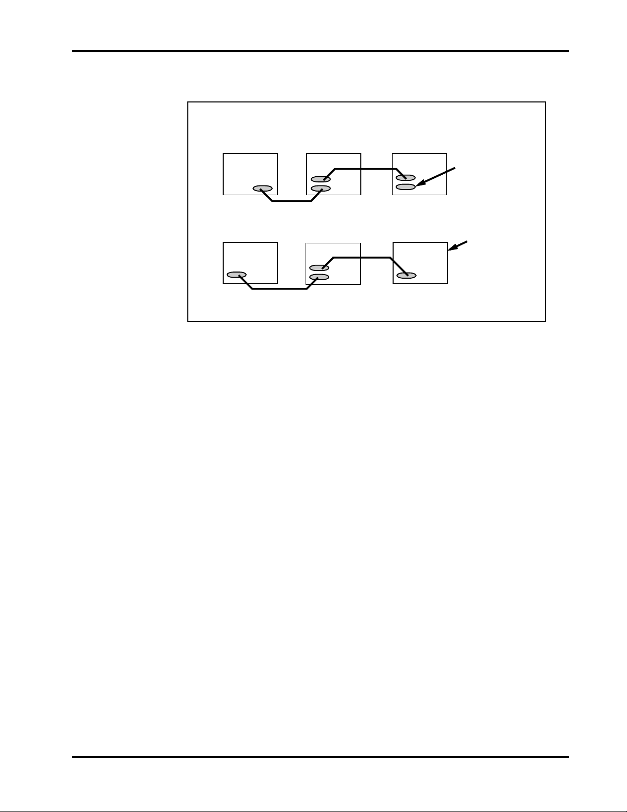
Figure 13. Mounting Hole Locations (Internal Drive without Rails).......27
Figure 14. Mounting Hole Locations (Internal Drive with Rails) ...........28
Figure 15. Rear Panel (External Model)..............................................30
Figure 16. Daisy Chain Diagram.........................................................31
Figure 17. Front Panel—Internal Model..............................................35
Figure 18. Front Panel—Internal Model with Rails..............................36
Figure 19. Front Panel—External Subsytem.......................................36
Figure 20. Cartridge Loading (Internal DAT Drive)..............................37
Figure 21. Locations on Drive.............................................................38
Figure 22. SCSI System Sample Configurations.................................46
Figure 23. Structure of a Basic Group................................................48
Figure 24. Track Configuration...........................................................50
Figure 25. Timing Tracking.................................................................53
Figure 26. Layout of a Single Data Space Tape..................................54
Figure 27. Appending Rules...............................................................55
Figure 28. Tolerance on Seamless Appending ...................................56
Figure 29. Layout of a Partitioned Tape..............................................58
Figure 30. Layout of SCSI/Data Compression Device.........................69
Figure 31. Simplified Block Diagram—Scorpion 24 DDS-3 Drive ........73
Figure 32. Block Diagram—SCSI Controller DAT Models...................74
Figure 33. Four-Head Design.............................................................75
Figure 34. Alternate Azimuth Angles ..................................................76
Figure 35. DDS Cartridge...................................................................80
Figure 36. Cartridge Design Features.................................................81
Figure 37. Write-Protect Tab on the DDS Cartridge............................81
Product Manual Page ix
Page 12

Figures
Page DAT Drives
x
Page 13

Introduction
Overview
1
®
The Seagate
computer environments that require high-performance, high-capacity data storage.
Based on a 3.5-inch mechanism, the internal and external Scorpion 24 models
provide 12 Gbytes of data-storage capacity, 24 Gbytes compressed, with a native
transfer rate of 1.1 Mbytes per second, 2.2 Mbytes per second compressed.
The Scorpion 24 drive combines established DAT technology, high-density
recording and hardware data-compression capability along with Seagate’s proven
computer grade design to provide unmatched reliability and performance
characteristics among DDS products. The Scorpion 24 is ideal for workstation,
server and network/enterprise applications such as:
z
Backup of high-capacity fixed discs
z
Data interchange between systems
z
Network server
z
Loader products
z
Online data collection
z
Near-line secondary storage for text, graphics or multimedia information of all
types
Scorpion
®
24 digital data storage (DDS) drive is designed for
z
Archival storage
DDS Format Standard Compatibility
The Scorpion 24 drive supports the DDS-3, DDS-2 and DDS recording formats.
Compatibility with each of these standards ensures complete write and read
interchange of recorded digital data between all compliant drive and media vendors.
Additionally, the Scorpion 24 drive supports DDS-DC, the DDS data compression
standard, effectively doubling storage capacity and transfer rates.
Product Manual Page 1
Page 14

Chapter 1 Introduction
The Scorpion 24 drive complies with:
z
The DDS recording format standard,
ANSI/ECMA-139, 3,81mm Wide Magnetic
Tape Cartridge for Information Interchange - Helical Scan Recording - DDS
Format.
z
The DDS-DC recording format standard,
ANSI/ECMA-150, 3,81mm Wide
Magnetic Tape Cartridge for Information Interchange - Helical Scan Recording DDS-DC Format using 60 m and 90 m Length Tapes.
z
The DDS-2 recording format standard,
ANSI/ECMA-198, 3,81mm Wide
Magnetic Tape Cartridge for Information Interchange - Helical Scan Recording DDS-2 Format using 120 m Length Tapes.
z
The DDS-3 recording format standard,
ANSI/ECMA-236, 3,81mm Wide
Magnetic Tape Cartridge for Information Interchange - Helical Scan Recording DDS-3 Format using 125 m Length Tapes.
Scorpion 24 Capacity and Transfer Rates
The Scorpion 24 provides the following capacities and transfer rates, depending on
recording mode and tape length:
Recording Mode
DDS DDS-DC DDS-2 DDS-3
Tape length 60 meter 90 meter 120 meter 125 meter
Capacity (native) 1.3 Gbytes 2.0 Gbytes 4.0 Gbytes 12.0 Gbytes
Capacity (compressed) N/A 4.0 Gbytes 8.0 Gbytes 24.0 Gbytes
Transfer rate (native) 780
Kbytes/sec
780
Kbytes/sec
780
Kbytes/sec
1.1
Mbytes/sec
In data-compression mode, the Seagate Scorpion 24 drive typically doubles the
storage capacity and transfer rate of the native uncompressed operation. Tape
capacity and sustained data-transfer rate are also dependent upon the
characteristics of the files being compressed, along with other system parameters,
including the speed of the host, the operating system and the application software
used.
The Scorpion 24 drive also offers synchronous or asynchronous SCSI transfers with
a high-speed burst data-transfer rate of 10 Mbytes per second.
The Scorpion 24 provides unmatched reliability through three levels of errorcorrection code (ECC) and the four-head design, which provides for read-after-write
(RAW) error detection and correction. The Scorpion 24 also contains an onboard
serial port that provides the capability for extensive testing of the drives.
Page 2 DAT Drives
Page 15

Introduction Chapter 1
Features
The Scorpion 24 DDS drive represents Seagate’s commitment to engineering
reliable and durable tape drive products that implement leading-edge technology.
Key features of the drive include:
z
Platform based on 3.5-inch DDS drive components
z
3.5-inch internal form-factor for installation in a 3.5-inch half-height space
(model STD124000N)
z
3.5-inch drive with factory-installed 5.25-inch mounting rails and bezel for
installation in a 5.25-inch half-height space (model STD224000N)
z
External subsystem with built-in, auto-sensing, worldwide power supply (model
STD624000N)
z
Capability to write and read DDS-3, DDS-2, DDS-DC and DDS cartridges
z
Advanced onboard DDS-DC hardware using Data Compression Lempel-Ziv
(DCLZ) data-compression algorithm
z
ANSI/ECMA DDS-3, DDS-2, DDS-DC and DDS tape format compliance for
compatibility and interchange
z
High-speed random access of 20 seconds (average) to any file on a 60 m tape;
30 seconds for a 90 m tape; 40 seconds on a 120 m tape; and 40 seconds on a
125 m tape
z
High-speed transfer rates for fast backups:
– 1.1 Mbytes per second (66 Mbytes per min) typical—uncompressed data
– 2.2 Kbytes per second (132 Mbytes per min) typical—compressed data
z
High-performance SCSI burst transfer rate of 7 Mbytes per second
asynchronous and 10 Mbytes per second synchronous
z
Flash memory to store setup parameters
z
Four-head design with RAW error detection and rewrites
z
Three levels of ECC to ensure data integrity
z
Uncorrectable error rate of less than 1 in 1015 bits
z
Flash memory to enable field firmware upgrades
z
Custom Seagate-designed LSI circuitry to reduce component count and boost
drive reliability
z
Advanced, single-chip, DDS formatter LSI
z
Low power consumption—less than 5.5 watts (typical) for internal drives
Product Manual Page 3
Page 16

Chapter 1 Introduction
z
Single-ended SCSI connection with these features:
– Embedded full LSI, high-speed SCSI-2 controller
– Software selectable synchronous or asynchronous SCSI data transfer
– Onboard output jack on internal models for configuring the SCSI
address if repackaged in an external box
z
Automatic power-on self-tests available
z
Manual emergency cartridge ejection procedure
z
Support for TapeAlert™ Certified Solutions
Models
The Scorpion 24 3.5-inch and 5.25-inch internal drive form-factors are tailored for
easy installation in today’s computers, and the full-featured embedded SCSI
controller facilitates easy integration into a variety of systems.
Scorpion 24 Model Names
Capacity 24.0 Gbytes*
3.5-in internal STD124000N
5.25-in internal STD224000N
External STD624000N
*Typical with data compression
Scorpion 24 models include:
z
A 3.5-inch, half-height DDS-3 drive that mounts internally (model
STD124000N).
z
A 5.25-inch, half-height DDS-3 drive that consists of a 3.5-inch drive with 5.25inch mounting rails and bezel that mounts internally in a 5.25-inch, half-height
space (model STD224000N).
z
A complete external subsystem that contains the 3.5-inch DDS-3 drive and
built-in worldwide power supply (model STD624000N).
Page 4 DAT Drives
Page 17
Introduction Chapter 1
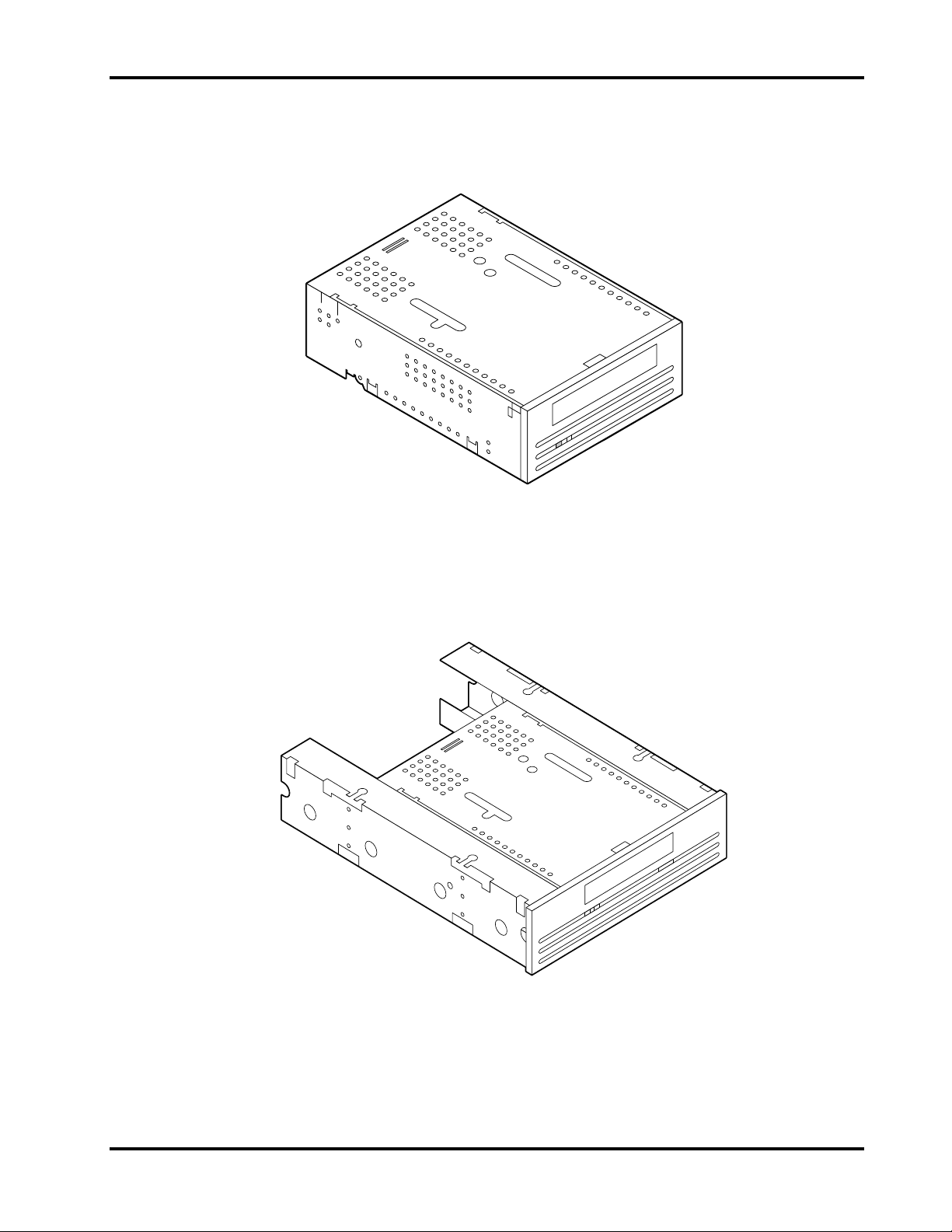
Figures 1, 2 and 3 illustrate the internal, internal with rails and external drives,
respectively.
Figure 1. 3.5-Inch Internal DDS Drive
Figure 2. 5.25-Inch Internal DDS Drive
Product Manual Page 5
Page 18
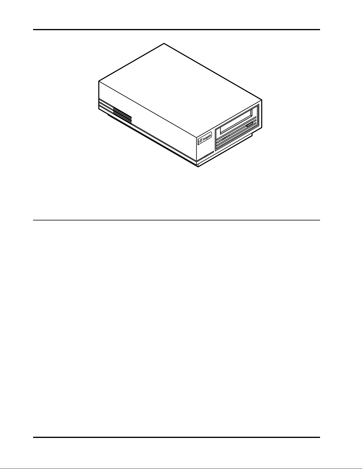
Chapter 1 Introduction
Figure 3. External DDS Drive
DAT Technology Overview
Developed for the audio electronics market, DAT technology was first applied in
computer peripherals in the late 1980s. Unlike traditional magnetic tape audio
cartridge products, DAT technology proves inherently reliable through the
scan recording method,
error rate. All DAT products, including computer implementations, use the helical
scan recording method. This recording method has been used in professional video
tape recorders (VTRs) since 1956 and in home video cartridge recorders (VCRs)
since 1974. In 1986, DAT products that used helical scan technology were first
developed for audio applications. DAT consumer products are specifically designed
for digital audio recording and playback.
Helical Scan Recording
Helical scan recording was originally developed as a method of efficiently recording
high-quality television signals on a relatively slow moving tape. It requires that both
the tape and the recording head move simultaneously. This recording method
results in an extremely high recording density, far higher than can be achieved with
stationary-head devices such as 1/2-inch open-reel or 1/4-inch cartridge tapes. (See
chapter 8, “Helical Scan Recording—Four-Head Design” for additional information.)
In helical scan recording, both the read and write heads are located on a rapidly
rotating cylinder or drum. The cylinder is tilted at an angle in relation to the vertical
axis of the tape. As the tape moves horizontally, it wraps around the part of the
circumference of the cylinder (102°) so that the head enters at one edge of the tape
and exits at the other edge before the tape unwraps.
helical
which provides a high recording density with a very low
Page 6 DAT Drives
Page 19

Introduction Chapter 1
The horizontal movement of the tape in combination with the angular movement of
the cylinder causes the track to be recorded diagonally across the tape rather than
straight down its length. The resulting recorded track, nearly one inch, is
approximately eight times longer than the width of the tape.
Recording Formats
The Seagate Scorpion 24 DDS drive is designed to comply with the industrystandard DDS-3, DDS-2, DDS-DC and DDS recording formats. These formats are
summarized in the following text.
DDS-3 Recording Format
The DDS-3 recording format provides for writing data in helical tracks that are the
same width as DDS-2. The significant capacity increase associated with DDS-3 is
achieved by: 1) doubling linear recording density from 61 Kbpi (DDS-2) to 122 Kbpi
along with the use of PRM L enc oding; 2) increasing tape length to 125 meters and
3) using the timing tracking system, which eliminates the need for dedicated top and
bottom servo burst information associated with the previous ATF system.
DDS-2 Recording Format
DDS Recording Format
The DDS-2 or narrow track recording format provides for writing data in helical
tracks that are narrower than the previous DDS track width. This format doubles
capacity by increasing track density one and a half times, along with a 33% increase
in tape length; the higher output MP+ media associated with the 120-m DDS-2
cartridges ensures reliable data integrity given the decrease in track widths from
13.6 µm with DDS and DDS-DC to 9 µm with DDS-2.
This standard format was codeveloped by DDS manufacturers to support DAT
devices as computer peripherals. The objectives of DDS are to maximize storage
capacity and performance, facilitate data interchange, provide compatibility with
existing tape storage command sets and provide extremely fast random access.
The DDS format also takes advantage of the helical scan recording method and the
inherent error correction capability of the DAT technology to augment error detection
and correction.
The format consists of a finite sequence of data groups where each data group is a
fixed-length recording area. A data group is made up of 22 data frames and 1 ECC
frame; each frame is made up of two helical scan tracks. The advantages of the
fixed-length data group is that ECC is easily generated, and buffering requirements
are simplified. (See Chapter 6, “Tape Formats,” for additional information.)
Although data groups are fixed-length and always contain 22 data frames, the DDS
format is designed such that variable-length computer records can be stored in the
fixed-length data groups.
Product Manual Page 7
Page 20

Chapter 1 Introduction
DDS-DC Recording Format
A superset of the basic DDS format, DDS-DC drives can write compressed and
uncompressed data to the same cartridge. Because DDS-DC is based on the DDS
format, backward-compatibility is maintained.
Introduced by the DDS Manufacturers Group and approved by ANSI and ECMA,
DDS-DC is a
lossless
compression algorithms based on substitution—such as those of the
record compression
industry-standard format that provides support for
Lempel-Ziv family.
This format supports compressed and uncompressed records. A recorded DDS
cartridge may contain compressed records, uncompressed records, filemarks and
setmarks. Compressed records exist within recorded objects called
entities
. Entities
and uncompressed records are collected into groups.
Many aspects of the DDS-DC format are identical to those of the DDS format:
z
The series of transformations (randomizing, interleaving, generation and
inclusion of two Reed-Solomon error-correction codes) applied to a group
before recording
z
The tape layout
z
The third group-based level of Reed-Solomon error-correction codes (C3)
The only differences between the DDS and DDS-DC formats are in the contents of
the groups.
Page 8 DAT Drives
Page 21

Specifications
Overview
This chapter includes technical specifications for the internal and external SCSI
drives. This information covers the following specifications and requirements:
z
z
z
z
z
z
2
Physical specifications
Power requirements
Drive performance specifications
Environmental requirements
DAT cartridge specifications
Regulatory compliance
Physical Specifications
The physical specifications of the Scorpion 24 internal and external models are
listed in the following table:
Specification Internal Internal with rails External
Height 1.6 in/41.2 mm 1.6 in/41.2 mm 2.7 in/69 mm
Width 4.0 in/101.6 mm 5.7 in/146.0 mm 6.1 in/155.0 mm
Length 5.7 in/146.0 mm 6.9 in/175.0 mm 9.3 in/236.0 mm
Weight 2.0 lb/0.85 kg 2.4 lb/1.1 kg 4.1 lb/1.8 kg
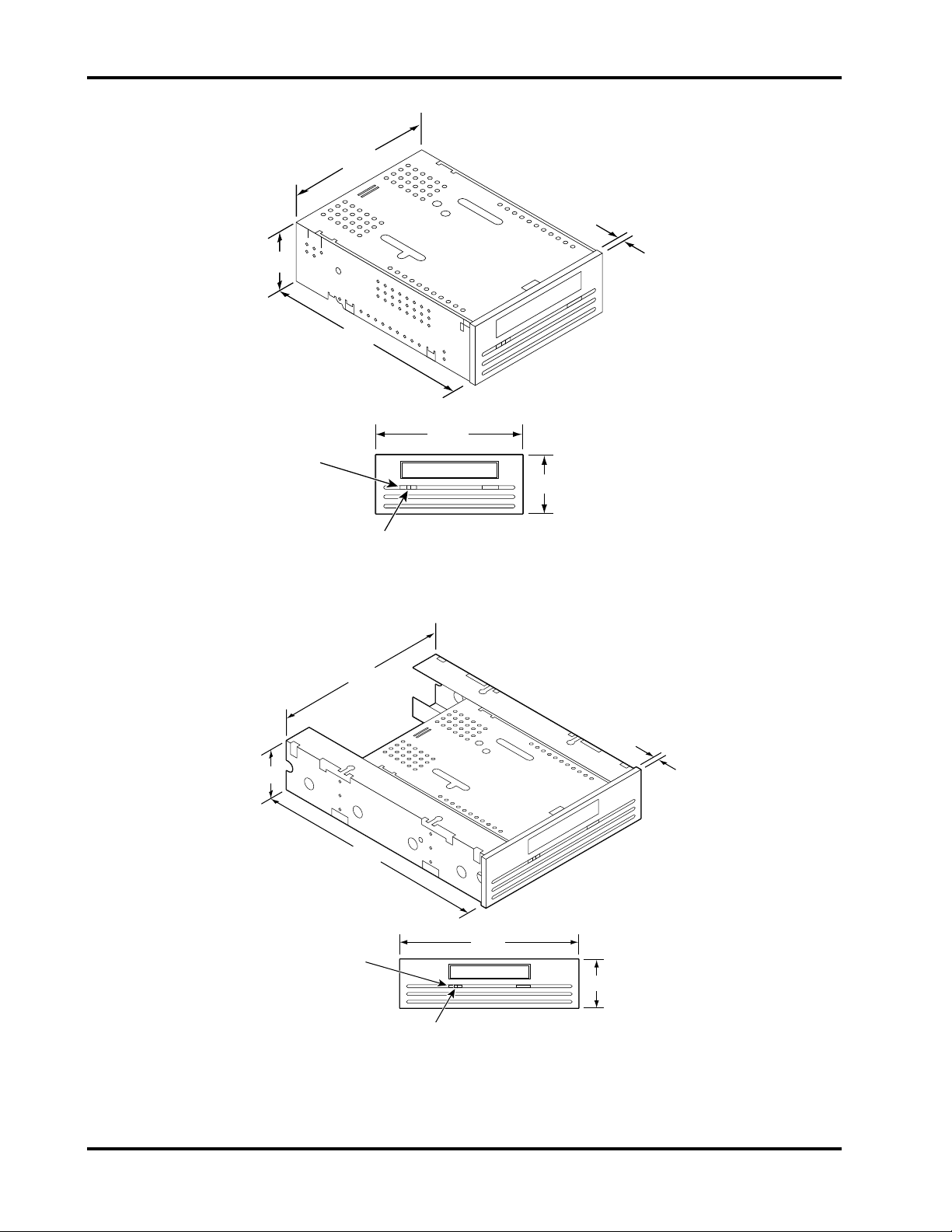
Figures 4, 5 and 6 illustrate the general dimensions of the internal and external drive
models. Drive dimensions are in millimeters.
Product Manual Page 9
Page 22
Chapter 2 Specifications
101.6
6
41.3
146
Cassette
104.1
in Place (Green)
41.2
Drive Busy (Yellow)
Figure 4. Internal DDS Drive—General Dimensions
146
41.4
174.6
6
Cassette
in Place (Green)
Drive Busy (Yellow)
149.1
41.2
Figure 5. Internal DDS Drive with Rails—General Dimensions
Page 10 DAT Drives
Page 23
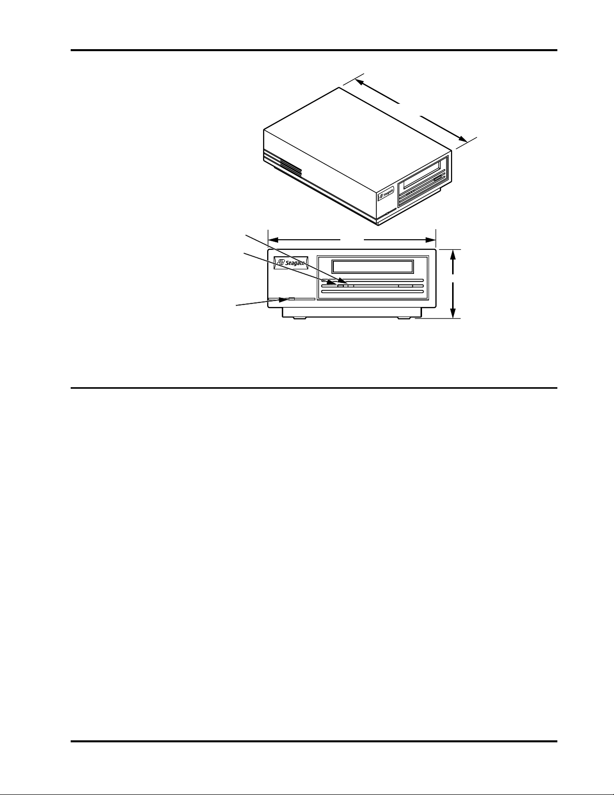
Specifications Chapter 2
236
Drive Busy
(Yellow)
Cassette in Place
(Green)
Power On
(Green)
155
69
Figure 6. External Subsystem—General Dimensions
Power Specifications
The following table lists the power specifications for the internal Scorpion 24 drives.
DC Voltage +12 VDC +5 VDC
Voltage Tolerance + or – 10% + or – 7%
Operational Current 250 milliamps 600 milliamps
Standby Current 50 milliamps 550 milliamps
Peak 600 milliamps 800 milliamps
Ripple (peak-to-peak)
Power dissipation
(Standby)
Power dissipation
(Operating)
The following table lists pin assignments of the power connector for the internal
models.
Pin Assignment
1 +12 VDC
2 +12 return
3 +5 return
4 +5 VDC
≤
100 mV
≤
100 mV
< 3.3 watts < 2.2 watts
< 5.5 watts < 5.5 watts
Product Manual Page 11
Page 24

Chapter 2 Specifications
The external drives have a built-in power supply that senses the incoming voltage
and automatically adapts to voltages within the range of 100 to 240 volts, 50 to 60
Hz. The following table lists its power specifications.
Specification AC Input Voltage
100 (Japan) 120 (US) 240 (European)
AC Input Current 100 milliamps 85 milliamps 170 milliamps
AC Input Power 10.0 watts 10.0 watts 10.0 watts
Drive Performance Specifications
The following table lists the specifications for the Scorpion 24 drive.
Capacity
60 m MP
90 m MP
120 m MP+
125 m MP++
2.6 Gbytes
4.0 Gbytes
8.0 Gbytes
24.0 Gbytes
Recording density 122,000 bpi
Flux density 152,400 ftpi
Track density 2,804 tpi
Error recovery Read-after-write
Reed Solomon ECC (C3 - 3 levels)
Recording unrecoverable errors < 1 in 10
Tape drive type Computer grade 4DD mechanism
Head configuration 2 read heads, 2 write heads
Recording format DDS-3
Recording method Helical scan (R-DAT)
Cartridge 2.9 in × 2.1 in × 0.4 in
Transfer rate (sustained) 2,200 Kbytes per sec DC ON
Synchronous transfer rate (burst) 10 Mbytes per sec max
Asynchronous transfer rate (burst) 7 Mbytes per sec max
Search speed 200 X normal speed
Average access time
60 m cartridge
90 m cartridge
120 m cartridge
125 m cartridge
Drum rotation speed 4,000 RPM (DDS-3 mode)
Tape speed 0.43 in per sec
Head-to-tape speed 246.94 in per sec
<20 sec
<30 sec
<40 sec
<40 sec
8,000 RPM (DDS-2, DDS modes)
15
data bits
Page 12 DAT Drives
Page 25

Specifications Chapter 2
Environmental Requirements
The following table lists the environmental specifications for DDS drives. You can
mount internal DDS drives either vertically (drive left side up or right side up) or
horizontally.
Specification Operational Nonoperational
Temperature +41o to +113oF
(+ 5o to + 45oC)
Thermal gradient 2oC per minute
(no condensation)
Relative humidity 20% to 80%
noncondensing
Maximum wet bulb temperature 78.8oF (26oC) No condensation
Altitude –100 to +4,575 meters –300 to +15,200
Vibration — 1.5 g (5 to 500 Hz)
Sweep Test 1.20 mm peak-to-peak
(5–17 HZ)
0.73 G peak (17 to 150 Hz)
0.50 G peak (150–500 Hz)
Sweep Rate 8 decades per hour —
Dwell Test (15 min) 0.90 mm peak-to-peak
(5–17 Hz)
0.55 G peak (17–150 Hz)
0.25 G peak (150–500 Hz)
Acoustic level idling (A-wt sum) 45 dBA maximum —
Acoustic level operational
(A-wt sum)
Shock (1/2 sine wave) 10 Gs peak, 11 msec 50 Gs peak, 11 msec
50 dBA maximum
(measured in suitable
enclosure at 3-ft distance
and operator height)
1
1
o
–40
to +149oF
(–40o to + 65oC)
Below condensation
0% to 90%
noncondensing
meters (power off)
—
—
—
—
—
—
—
2
2
1. Mechanism and media 2. Mechanism
DDS Cartridge Specifications
DDS drives provide maximum data integrity and reliability when Seagate-qualified
DDS cartridges are used as the recording media. Seagate maintains an ongoing
program to qualify manufacturers of DDS cartridges.
The following cartridges are recommended:
z
DDS data cartridge: model M31300, 60-meter tape
z
DDS data cartridge: model M32000, 90-meter tape
z
DDS-2 data cartridge: model M34000, 120-meter tape
z
DDS-3 data cartridge: model M312000, 125-meter tape
z
DDS cleaning cartridge: model M91301
Contact your Seagate sales representative for information on qualified DDS data
and cleaning cartridge manufacturers and models.
Product Manual Page 13
Page 26

Chapter 2 Specifications
Regulatory Compliance
These DDS drives comply with the regulations listed in the following table.
Agency Regulation
CSA C22.2, No. 950-M89
TUV-RHEINLAND EN 60 950
UL 1950
FCC Class A and Class B
CE CE compliance
1. Required compliance for external model; verification on file for internal models.
Use these drives only in equipment where the combination has been determined to
be suitable by an appropriate certification organization (for example, Underwriters
Laboratories Inc. or the Canadian Standards Association in North America). You
should also consider the following safety points:
Install the drive in an enclosure that limits the user’s access to live parts, gives
adequate system stability and provides the necessary grounding for the drive.
1
Provide the correct voltages (+5 VDC and +12 VDC) based on the regulation
applied—Extra Low Voltage (SEC) for UL and CSA and Safety Extra Low
Voltage for BSI and VDE (if applicable).
Page 14 DAT Drives
Page 27

Installation
Introduction
3
This chapter explains how to install the Scorpion 24 drive. Some of the information
relates to all models; other information is specifically aimed at either the internal or
external models. The following paragraphs briefly outline the organization of this
chapter.
Guidelines and Cautions: lists guidelines for handling the internal drive.
z
Unpacking and Inspection: contains general information that you should read
z
before installation.
Cabling and Connectors: gives specific cabling requirements and connector
z
pinouts for the drive.
Installing the Internal Drives: describes installing the 3.5-inch internal drive
z
and the 3.5-inch drive with 5.25-inch mounting rails and bezel.
Installing the External Drive: describes installing the external subsystem.
z
Guidelines and Cautions (Internal Models)
The following guidelines and cautions apply to handling and installing the Scorpion
24 internal drive. Keep them in mind as you install the drive.
z
Internal drives contain some exposed components that are sensitive to static
electricity. To reduce the possibility of damage from static discharge, the drives
are shipped in a protective antistatic bag.
z
Do not remove the drive from the antistatic bag until you are ready to install it.
z
Before you remove the drive from the antistatic bag, touch a metal or grounded
surface to discharge any static electricity buildup from your body.
z
Hold the drive by its edges only, and avoid direct contact with any exposed
parts of the printed circuit board (PCB).
z
While not installed, always lay the drive either on top of the antistatic bag or
place it inside of the bag to reduce the chance of damage from static discharge.
Product Manual Page 15
Page 28

Chapter 3 Installation
Unpacking and Inspection
Although drives are inspected and carefully packaged at the factory, damage may
occur during shipping. Follow these steps for unpacking the drive.
1. Visually inspect the shipping containers and notify your carrier immediately of
any damage.
2. Place shipping containers on a flat, clean, stable surface; then carefully remove
and verify the contents against the packing list.
If parts are missing or the equipment is damaged, notify your Seagate
representative.
3. Always save the containers and packing materials for any future reshipment.
Cabling and Connectors
The Scorpion 24 drive provides a standard single-ended SCSI interface. ANSI SCSI
standards specify the technical requirements for correctly cabling and connecting
single-ended devices. This section provides some basic information about SCSI
cabling and connectors for the drives.
Cabling Considerations
You can use either a 50-pin flat cable or a 25-signal twisted-pair cable with a
maximum length of 6 meters (19 feet) to connect the drives to the SCSI host
adapter output. If twisted-pair cabling is used, connect the twisted pairs to physically
opposing contacts on the connector.
A stub length no greater than 0.1 meter should be used off the mainline connection
within any connected equipment.
The cable characteristic impedance should be between 90 ohms and 140 ohms. A
cable characteristic impedance of greater than 100 ohms is recommended.
To minimize noise and ensure even distribution of terminator power, the minimum
recommended conductor size is 28 AWG (0.08042 mm
Electrical Characteristics
This section lists measurements of various electrical signals in relation to the singleended SCSI connection. For these measurements, SCSI bus termination is
assumed to be external to the SCSI device.
2
).
Page 16 DAT Drives
Page 29

Installation Chapter 3
All signals except GROUND and TEMPWR must be terminated at both ends of the
cable. Each signal termination consists of 220 ohms (± 5%) to TEMPWR and 330
ohms (± 5%) to GROUND and must meet the following specifications or
requirements:
z
Terminators must supply a characteristic impedance of 100 to 132 ohms.
z
External terminators must be powered by the TEMPWR line, and units that
provide terminator power to the cable must have:
V
= 4.25 to 5.25 VDC
TERM
900 milliamps minimum source drive capability
The external drive normally supplies terminator power to the SCSI bus.
z
When TEMPWR matches the above values, the voltage of released signal lines
must be at least 2.5 VDC.
z
When a driver asserts a line and pulls it to 0.5 VDC, the current available to the
signal line driver may not exceed 48 milliamps. The first two terminators may
only supply 44.8 milliamps of this current.
z
When at least one device supplies TEMPWR, these conditions may be met by
any valid configuration of targets and initiators.
All signals use open-collector drivers. The output characteristics (measured at the
connector of the drive) of signals driven by the drive are:
z
Signal assertion (low-level output voltage): 0.0 to 0.5 VDC at 48 milliamps
sinking
z
Signal negation (high-level output voltage): 2.5 to 5.25 VDC
Signals received by the drive have the following characteristics.
z
Signal assertion (low-level input voltage): 0.0 to 0.8 VDC
z
Signal negation (high-level input voltage): 2.0 to 5.25 VDC
z
Maximum input load (low-level input current): –0.4 at 0.5 VDC
z
Minimum input hysteresis: 0.2 VDC
Product Manual Page 17
Page 30

Chapter 3 Installation
SCSI Connector—Internal Models
The internal drive provides a 50-pin, right-angle, dual-row connector on the main
PCB at the rear of the drive. The pin assignments for this single-ended connector
are listed in the following table.
Note. All odd pins, except pin 25, are connected to signal ground at the drive. Pin
25 is left open. A signal name or abbreviation preceded by a dash indicates
that the signal is active-low.
Pin Assignment
2 –DB(0)
4 –DB(1)
6 –DB(2)
8 –DB(3)
10 –DB(4)
12 –DB(5)
14 –DB(6)
16 –DB(7)
18 –DB(P)
20 GROUND
22 GROUND
24 GROUND
26 TERMINATOR POWER
28 GROUND
30 GROUND
32 –ATN
34 GROUND
36 –BSY
38 –ACK
2
–
40
RST
42 –MSG
44 –SEL
46 –C/D
48 –REQ
50 –I/O
1
1. The +5V drive supply is available on the SCSI connector as a terminator power
option. This pin is connected to the +5V through a diode. The option is selected
by a jumper at the rear of internal drives. Terminator power disabled is the
factory default.
2. ANSI defines –RST as a bidirectional pin. On the drive, –RST is input only.
Page 18 DAT Drives
Page 31

Installation Chapter 3
SCSI Connector—External Models
The external drive provides two 50-pin, shielded connectors (ANSI Alternative 2) on
the rear panel of the drive. These connectors consist of two rows of ribbon contacts
spaced 2.16 mm (0.085 in) apart.
These two connectors facilitate adding the drive to a daisy-chain configuration.
Either connector is a SCSI IN connection; the other is a SCSI OUT connection.
When the drive is the last device in the chain (or the only device), an external
terminator is plugged in the SCSI OUT connector.
The pin assignments for these single-ended connectors are listed in the following
table.
Note. Pins 1 through 12 and 14 through 25 are connected to ground. Pin 13 is
open. A signal name or abbreviation preceded by a dash indicates that the
signal is active-low.
Pin Assignment
26 –DB(0)
27 –DB(1)
28 –DB(2)
29 –DB(3)
30 –DB(4)
31 –DB(5)
32 –DB(6)
33 –DB(7)
34 –DB(P)
35 GROUND
36 GROUND
37 GROUND
38 TERMINATOR POWER
39 GROUND
40 GROUND
41 –ATN
42 GROUND
43 –BSY
44 –ACK
–
45
46 –MSG
47 –SEL
48 –C/D
49 –REQ
50 –I/O
RST
Product Manual Page 19
Page 32
Chapter 3 Installation
Installing Internal Drives
The two internal models are a 3.5-inch drive that mounts internal to the computer in
a 3.5-inch, half-height space and a 3.5-inch drive with mounting rails and bezel for
internal installation in a 5.25-inch, half-height space.
Installing these two models consists of a few easy steps:
1. Configure the switchbank parameters and set the jumpers.
2. Mount the drive unit.
3. Complete the power and interface connections.
The installation procedure is the same for both models except physically mounting
the unit in the computer. The following text explains the installation steps for both
models.
Configuring Options
You can configure various operational options on the Scorpion 24 by setting the
switches on a switchbank at the base of the drive or by setting jumpers on a jumper
block at the rear of the drive. The directions for setting both switches and jumpers
are given in the following subsections.
Setting the Switchbank Parameters
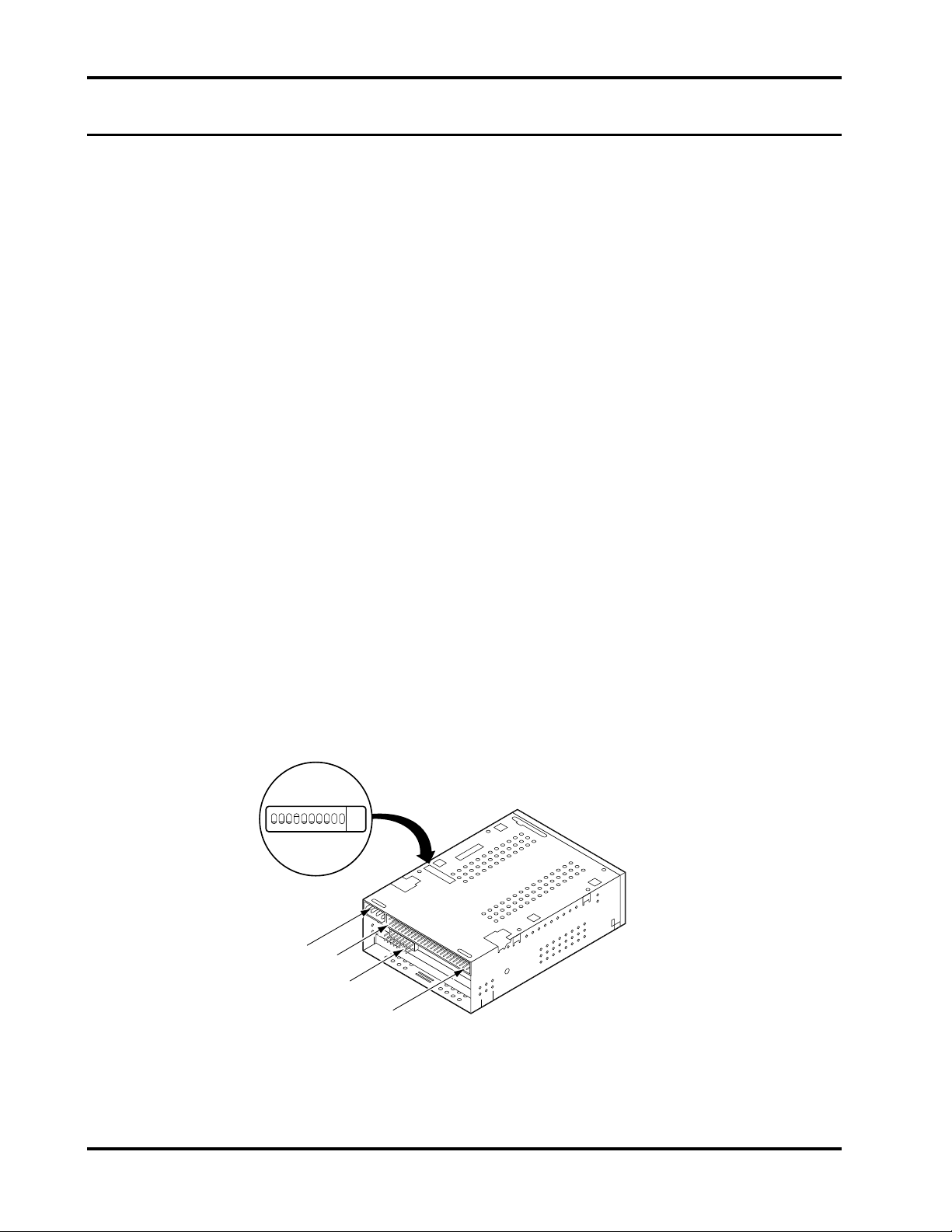
Set the switches before you install the drive in the computer. Figure 7 illustrates the
switchbank location for the 3.5-inch internal drive (bottom of the drive is shown).
123456789
F
F
O
Power
Connector
10
Pin 1
Jumper
Block
SCSI
Connector
Figure 7. Switchbank Access—3.5-Inch Internal Model
Page 20 DAT Drives
Page 33
Installation Chapter 3
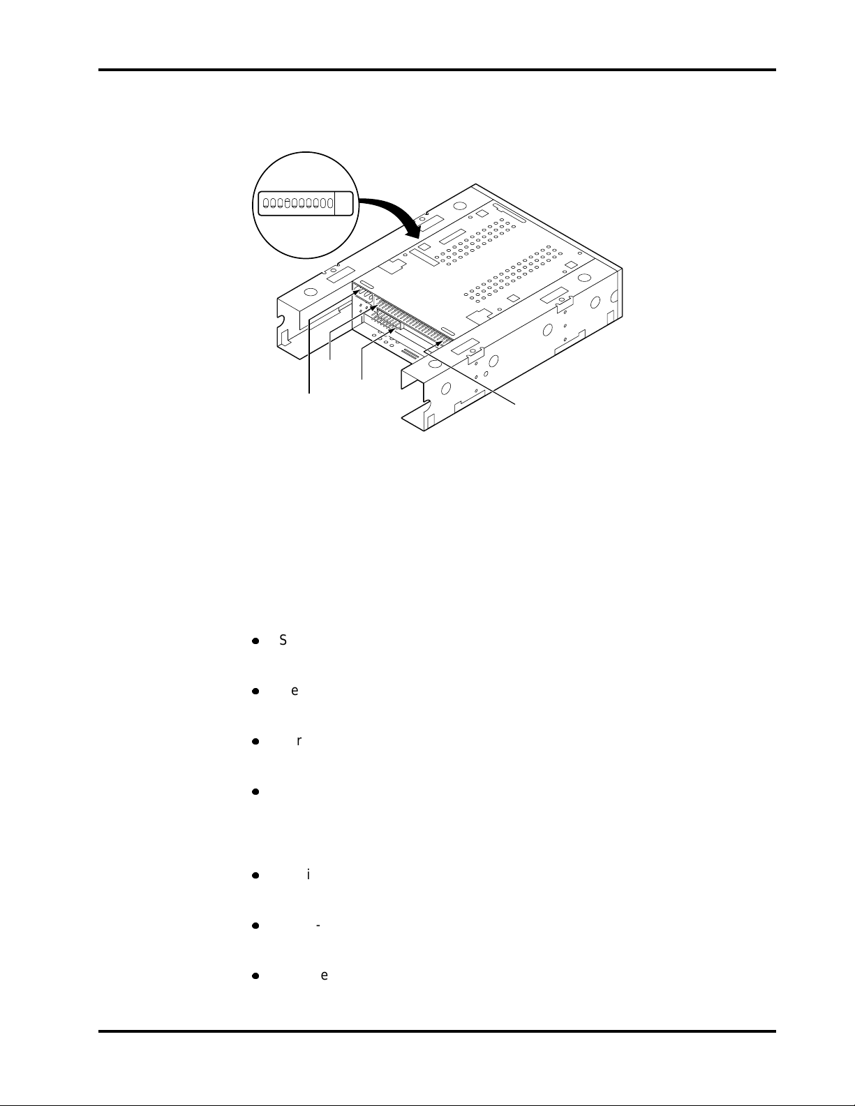
Figure 8 illustrates the switchbank location for the 5.25-inch internal drive (bottom of
the drive is shown).
123456789
F
F
O
Connector
Power
10
Pin 1
Jumper
Block
SCSI
Connector
Figure 8. Switchbank Access—5.25-Inch Internal Model
The Scorpion 24 switc hbank allows y ou to configure the S CS I device address,
media-recognition system (MRS) mode, parity check, DDS pass-through mode
(data-compress ion m ode) , Seagate’s selectable inquiry string and power- on s elf-test
(POST).
Following are brief descriptions of the various positions and with their def ault values.
z
SCSI device address (S1, S2, S3):
Default: SCSI ID = 0 (S1= OFF, S2 = OFF, S3 = OFF)
z
Media-recognition system (MRS) mode (S4):
Default: MRS check disabled (S4 = ON)
z
Parity check enable/disable (S5):
Default: Parity disabled (S5 = OFF)
z
DDS pass-through mode enable/disable (S6):
Default: Pass-through mode disabled (S6 = OFF)
When S6 is OFF, data compression is enabled.
When S6 is ON, data compression is disabled.
z
Inquiry string selection (S7):
Default: Seagate inquiry string (S7 = ON)
z
Power-on self-test enable/disable (S8):
Default: Power-on self-test disabled (S8 = OFF)
z
Reserved (S9 and S10):
Do not use these switches.
Product Manual Page 21
Page 34

Chapter 3 Installation
Figure 9 shows the default switch settings.
OFF
ON
OFF
ON
S9
S10
Reserved
(do not use)
S8
Self-test
Disable
Enable
S7
Inquiry
String
Archive
Seagate
DDS Pass-
through
DDS-DC
DDS
Parity
Disable
Enable
MRS
Mode
MRS
All
S2S3S4S5S6
SCSI ID Selection
OFF
OFF
OFF
OFF
ON
ON
ON
ON
OFF
OFF
ON
ON
OFF
OFF
ON
ON
S1
OFF
ON
OFF
ON
OFF
ON
OFF
ON
SCSI ID
0
1
2
3
4
5
6
7
Figure 9. Dip Switch Default Settings
If you need to change any of the factory-default settings, you must first power-cycle
the drive by turning it off and then on again, or a SCSI Bus Reset command must be
received for the new switch settings to take effect.
If the default settings are correct for your system,
go to: “Mounting the Drive” on page 27.
Otherwise, refer to the appropriate following section, make the changes, then go to:
“Mounting the Drive” on page 27.
SCSI Device Address (S1, S2, S3)
The three switches S1, S2 and S3 correspond to the SCSI device address
identification bits 0 (LSB) through 2 (MSB), respectively.
The default setting is SCSI device address 0 (S1 through S3 = OFF).
Be sure that no other device on the SCSI bus has the same SCSI address.
Media Recognition System (MRS) (S4)
S4 = ON disables the MRS check
S4 = OFF enables the MRS check
The default is MRS disabled (S4 = ON).
If S4 is ON, the drive writes or reads both MRS and non-MRS 4-mm media. If S4 is
OFF, the drive only writes to MRS media. The drive reports a check condition if the
media is nondata grade. The Sense Key is 07, Data Protect. The additional Sense
Code and qualifier is 30/00, incompatible media installed.
Page 22 DAT Drives
Page 35

Installation Chapter 3
Parity Check Enable/Disable (S5)
The S5 switch enables or disables parity checking for the SCSI bus.
The default is parity disabled (S5 = OFF).
S5 = ON enables parity checking
S5 = OFF disables parity checking
DDS Pass-Through Mode Enable/Disable (S6)
The S6 switch enables or disables DDS pass-through mode. The default is DDS
pass-through mode disabled (S6=OFF).
S6 = ON enables DDS pass-through mode
S6 = OFF disables DDS pass-through mode
If you are using the DIP switches to set the DDS pass-through mode, move the
DDS pass-through jumpers on the jumper block to the OFF position.
When S6 is OFF, DDS-DC data compression is ENABLED during writing.
When S6 is ON, DDS-DC data compression is DISABLED. During a read operation,
compressed data is always decompressed, regardless of the position of S6.
The function of the S6 switch can be overridden by the proper SCSI
command issued from the host computer. Regardless of the position of S6, the
Mode Select command can independently enable or disable data compression.
Inquiry String (S7)
The S7 switch is used to select the SCSI inquiry string. The default setting (S7=ON)
enables the Seagate inquiry string. You can set it to Archive to provide compatibility
with older backup software.
S7 = ON enables Seagate inquiry string
S7 = OFF enables Archive inquiry string
Power-on Self-Test Mode Enable/Disable (S8)
The S8 switch enables or disables execution of power-on self-test (POST)
diagnostics when the drive is first powered on. When ON, the drive responds to
SCSI commands only after successful completion of the test (about 5 seconds).
The default is power-on self-test mode disabled (S8 = OFF).
Mode Select
S8 = ON enables power-on self-test mode
S8 = OFF disables power-on self-test mode
Switches 9 and 10
These switches are reserved and should not be used.
Product Manual Page 23
Page 36

Chapter 3 Installation
Setting the Jumpers
The jumper block on the Scorpion 24 provides additional access to settings for SCSI
ID, hardware data compression (HDC), enabling of the active terminator and
termination power.
For the SCSI ID jumper block settings to take effect, switches S1, S2 and S3 on the
switchbank must be in the OFF position.
Figures 10 and 11 illustrate the location of the jumper block for internal drives.
Jumper
Block
Pin 1
SCSI
Access for Manual
Cartidge Unload
Connector
Figure 10. Location of Jumpers for Internal Model
Pin 1
SCSI
Connector
Power
Connector
Jumper
Block
Power
Connector
Figure 11. Location of Jumpers for Internal Model with Rails
Page 24 DAT Drives
Page 37

Installation Chapter 3
Figure 12 shows the jumper configurations for the various SCSI device addresses
(IDs) and for the other options.
9 7654321
11
13
15
8
10
12
14
16
Pins
3, 4
Jumper OFF
SCSI
Pins
1, 2
ID
SCSI ID
HDC Disabled
(Jumper on pins 9 and 10)
Active Terminator Enabled
(Jumper on pins 11 and 12)
Not Connected (NC)
Termination Power ON
(Jumper on pins 15 and 16)
Jumper ON
Pins
5, 6
OFF OFF 0OFF
OFF OFF 1ON
OFF ON 2OFF
OFF ON 3ON
ON OFF 4OFF
ON OFF 5ON
ON ON 6OFF
ON ON 7ON
Figure 12. Jumper Configurations
If you need to change any of the factory-default settings, you must first power-cycle
the drive by turning it off and then on again, or a SCSI Bus Reset command must be
received for the new switch settings to take effect.
If the default address setting ID = 0 is correct for your system and you do not want
to change any other options, go to “Mounting the Drive” on page 27.
Otherwise, refer to Figure 9 on page 22 and the appropriate following section, make
the changes and then go to “Mounting the Drive.”
SCSI Device Address Jumpers
The three jumper locations for ID = 0, ID = 1 and ID = 2 correspond to the SCSI
device address identification bits 0 (LSB) through 2 (MSB), respectively.
The default setting is SCSI device address = 0.
Be sure that no other device on the SCSI bus has the same SCSI address.
Product Manual Page 25
Page 38

Chapter 3 Installation
Hardware Data Compression
Hardware data compression (HDC) is set by either using Switch S6 on the
switchbank or by using the jumper block.
The default setting is HDC enabled (no jumper on pins 9 and 10). Placing a jumper
on pins 9 and 10 overrides the switchbank setting and disables HDC.
As stated earlier, HDC can also be selected by the proper SCSI Mode Select
command issued by the host computer.
Active Terminator
The Scorpion 24 drive provides a jumper-selectable active terminator feature as a
substitute for terminator resistor packs. Termination is required if the drive is the
only device on the SCSI bus or in the event that the drive is the last device on the
bus.
The active terminator option is disabled as the factory-default.
If you need to have an active terminator for the drive, place a jumper across pins 11
and 12.
Terminator Power
The Scorpion 24 drive also provides jumper-selectable terminator power. You can
enable +5-volt terminator power if needed for terminators or other SCSI devices
through a jumper placement.
The factory-default for the Scorpion 24 drive is with terminator power disabled.
To enable terminator power, place the jumper shunt across pin 15 and 16 as shown
in Figure 12 on page 25.
Be sure the jumper is firmly in place.
!
Caution.
The Scorpion 24 also contains a terminator power fuse to prevent damage to drive
components in case the terminator power is shorted. The terminator power fuse is
located beside the terminator power jumper.
If the jumper is installed, be careful not to short the TERMPWR
signal to ground.
In the event that the fuse has blown to prevent damage to the drive, please return
the drive to the nearest Seagate authorized repair facility for replacement.
Page 26 DAT Drives
Page 39
Installation Chapter 3
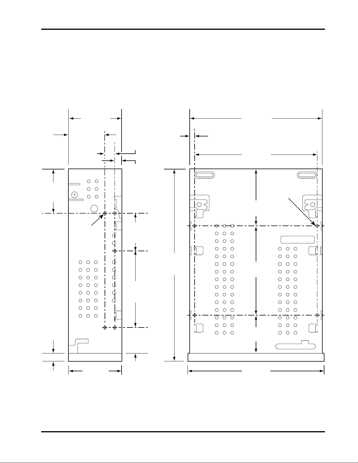
Mounting the Drive
You can install the internal drives in three different orientations: one horizontal (eject
button right) and two vertical (eject button up or eject button down).
The internal drive chassis contains threaded mounting holes for M3.0 metric screws.
The maximum length for the M3.0 metric screws is 4 mm. Four are located on the
bottom and five are on each side of the frame. See Figure 13 for details.
35.0 mm
(1.38 in)
2 Places
41.3 mm
(1.63 in)
28.3 mm
(1.11 in)
2 Places
M3.0 X
4 Deep Min.
10 Places
8.0 mm
(0.31 in)
2 Places
5.0 mm
(0.20 in)
2 Places
30.0 mm
(1.18 in)
2 Places
60.0 mm
(2.36 in)
2 Places
152 mm
(5.98 in)
2 Places
101.6 mm
(4.00 in)
3.8 mm
(0.15 in)
2 Places
94.0 mm
(3.70 in)
M3.0 X
4 Deep Min.
4 Places
45.0 mm
(1.77 in)
70.0 mm
(2.76 in)
6.0 mm
(0.24 in)
2 Places
21.0 mm
(0.83 in)
31.0 mm
(1.22 in)
2 Places
41.2 mm
(1.62 in)
104.1 mm
(4.10 in)
Side Bottom
Figure 13. Mounting Hole Locations (Internal Drive without Rails)
Product Manual Page 27
Page 40
Chapter 3 Installation
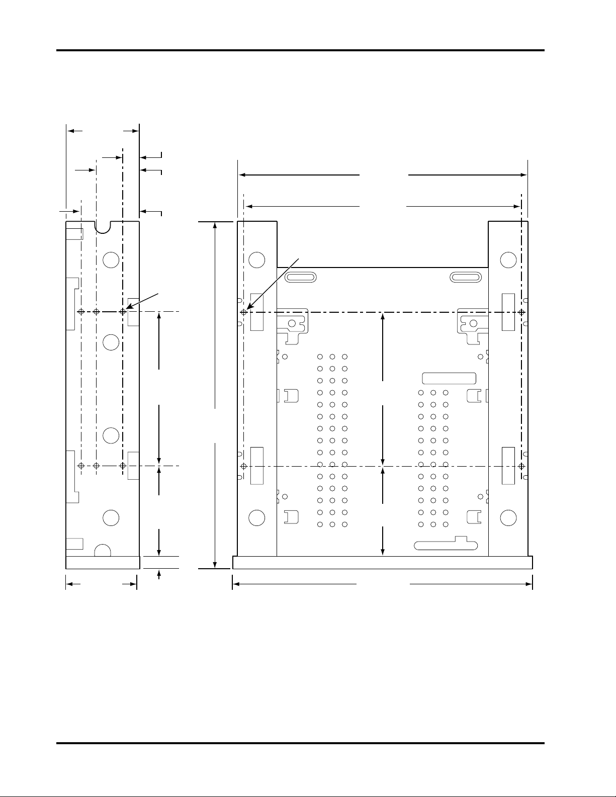
The chassis for the internal drive with rails contains threaded mounting holes for
M3.0 metric screws. The maximum length for the M3.0 screws is 4 mm. Four are
located on the bottom and six are on each side of the frame. See Figure 14.
41.3 mm
(1.63 in)
9.9 mm
(0.39 in)
2 Places
21.8 mm
(0.86 in)
2 Places
31.5 mm
(1.24 in)
2 Places
M3.0 X
4 Deep Min.
12 Places
79.4 mm
(3.13 in)
2 Places
146 mm
(5.74 in)
139.7 mm
(5.50 in)
M3.0 X
4 Deep Min.
4 Places
79.4 mm
(3.13 in)
180.6 mm
(7.11 in)
2 Places
41.2 mm
(1.62 in)
47.6 mm
(1.87 in)
2 Places
6.0 mm
(0.24 in)
2 Places
47.6 mm
(1.87 in)
148.5 mm
(5.84 in)
Side Bottom
Figure 14. Mounting Hole Locations (Internal Drive with Rails)
Page 28 DAT Drives
Page 41

Installation Chapter 3
Completing the Power and Interface Connections
The power and interface connectors for the internal models are located at the back
of the drive unit.
Figure 10 illustrates these connections for the 3.5-inch internal drive. Figure 11
illustrates these connections for the 5.25-inch internal drive with rails.
Note. Turn off all power before inserting connectors.
1. Connect the SCSI cable to the SCSI connector at the rear of the drive. Pin 1
on the SCSI connector is to your right as you look at the back of the drive.
(See Figures 10 and 11.) Your SCSI cable should be color-coded with Pin 1
highlighted by a color strip.
2. Make sure you connect Pin 1 on the cable to Pin 1 on the drive. Failure to do
so may make the drive inoperative.
3. Connect a power cable from the host system to the power connector on the
drive.
The recommended
with AMP 60617-1 pins or equivalent.
Installing External Drives
The compact external drive connects as a turnkey subsystem to the computer. The
drive is operational in either a vertical or horizontal orientation.
The following configuration is the standard default setup:
z
The drive writes or reads both MRS and non-MRS 4-mm media.
z
Parity is disabled.
z
DDS-DC data compression is enabled.
z
The power-on self-test (POST) diagnostics of the drive are disabled.
z
Terminator power is supplied to the SCSI bus.
Installing the external unit consists of a few easy steps:
power mating connector
requires an AMP 1-48024-0 housing
1. Select the SCSI address.
2. Complete the interface connection.
3. Complete the power cord connection.
Product Manual Page 29
Page 42

Chapter 3 Installation
Selecting the SCSI Address
The rear panel of the external drive contains the SCSI address selection push
switch, the two interface connectors, the ON/OFF switch and the power cord
connection. Figure 15 illustrates the rear panel.
Push
Switch
ON/OFF
Switch
6
Power
Connector
Figure 15. Rear Panel (External Model)
Locate the SCSI address push switch. Select the SCSI address for the drive by
pressing the (+) or (–) button until the desired address (0 through 7) appears in the
window.
If you need to change any of the factory-default settings, you must first power-cycle
the drive by turning it off and then on again, or a SCSI Bus Reset command must be
received for the new switch settings to take effect.
Completing the Interface Connection
The external drive provides two SCSI connectors to allow daisy-chain connections.
(See Figure 16.) Either connector can connect to the host computer or to any other
SCSI device in the daisy chain.
Turn off all power before connecting cables and the terminator.
Note.
z
When the drive is either the only drive in the chain or the last drive in the chain,
a single interface cable is attached to one connector, and a terminating plug is
installed in the other connector. (Seagate part number 38-9-74000000)
SCSI
Connectors
z
When the drive is within the chain, the interface cable from the preceding
device is connected in one connector, and an interface cable is also connected
from the other connector to the following device. In this case, no termination is
required.
Page 30 DAT Drives
Page 43
Installation Chapter 3
Figure 16 illustrates these daisy-chain connections
DAT DRIVE AS THE FINAL DEVICE
DAT DRIVE WITHIN A CHAIN
Figure 16. Daisy Chain Diagram
The same type of mating connector is used for either of the daisy-chain
connections. The mating interface connector for the external drive is a single-ended
connector as described earlier in this chapter.
Connecting the Power Cord
See Figure 15 for the location of the power cord connector.
DAT DRIVE
DAT DRIVE
TERMINATOR
FINAL
DEVICE
MUST HAVE
TERMINATOR
Insert the power cord mating connector into the connector on the rear panel. Be
sure the connection is secure. Plug the other end of the power cord into an electrical
outlet power strip, a continuous power supply or a wall receptacle.
Product Manual Page 31
Page 44

Chapter 3 Installation
Page 32 DAT Drives
Page 45

Drive Operations
4
Introduction
This chapter describes important operational procedures for the Scorpion 24 drive. It
covers the following topics:
z
Data compression operation
z
Front panel LED operation
z
Loading and unloading a cartridge
z
Using a blank cartridge
z
Using a cartridge that contains data
z
Loading revised firmware through Seagate firmware cartridges
Data Compression Operation
Default operation for the Scorpion 24 drive is to have data compression enabled—
the drive automatically compresses all data written to tape and decompresses all
compressed data read from tape.
The degree of compression varies due to the type of data being processed.
Data with high degrees of redundancy, such as structured database files or graphics
files, can be compressed most efficiently, often at a ratio of 2:1 or more. Data with
little redundancy, such as executable programs, can be compressed the least.
The SCSI
uncompressed mode for writing data regardless of the position of the jumper
position. When reading, the drive automatically selects compressed or
uncompressed mode, depending on the data that is read.
On internal models, a jumper on the rear panel can also be used to enable or
disable data compression. See Chapter 3 for more information.
Mode Select
command can switch the drive into compressed or
Product Manual Page 33
Page 46

Chapter 4 Drive Operations
Front Panel LED Operation
The front panel of the Scorpion 24 drive contains two rectangular LEDs. The yellow
rectangular LED indicates the drive status, and the green rectangular LED indicates
the cartridge status. These two indicators provide operating information for normal
conditions and error conditions.
The
drive status LED
z
When ON (lit), the drive is reading or writing the tape. (SCSI or drive activity is
present.)
z
When flashing rapidly, a hardware fault has occurred. If this situation occurs
immediately after power-on and you have enabled the power-on self-test
through a jumper setting, the power-on self-test may have failed. In that case,
the drive will not operate.
Note. During a SCSI Prevent Media Removal command, the LED is always ON.
Note. Do not push the eject button while the yellow drive status LED is ON. If you
do, the operation in progress is aborted and the cartridge ejected, possibly
causing a loss of data.
indicates the following conditions:
The
cartridge status LED
z
When ON (lit), a cartridge is inserted and the drive is operating normally.
z
When flashing slowly, a cartridge is inserted but is generating excessive media
indicates the following conditions:
errors beyond a predefined error threshold. This signal is a warning only and
does not indicate a loss of data.
Whenever the cartridge status LED flashes slowly to warn of excessive media
errors, the operator should clean the drive heads using an approved cleaning
cartridge (such as the Seagate Model M7301).
If the LED continues to flash or flashes while ejecting a cartridge, use a new
cartridge for future writes as a precaution.
Note. As routine maintenance, the drive heads should be cleaned after every 25
hours of operation. Even though the Scorpion 24 drive has an internal
cleaning mechanism, a regular cleaning routine helps reduce errors due to
environmental contaminants such as dust, carpet fibers or airborne debris.
z
When flashing rapidly, the drive could not write the tape correctly (maximum
rewrite count exceeded). The
WRITE
operation failed.
First, clean the drive heads using an approved cleaning cartridge, such as the
Seagate Model M7301. If the LED continues flashing, use a new cartridge for
future writes.
Page 34 DAT Drives
Page 47

Drive Operations Chapter 4
Audio Mode Indicator
The cartridge status LED flashing in conjunction with the drive status LED indicates
that a prerecorded audio cartridge is inserted and is playing automatically.
External Power LED
The round, green LED on the external drive illuminates when power is applied to the
drive.
The following table summarizes the operation of the front-panel LEDs. See the
previous explanations to remedy fault conditions.
LED Action Meaning
Yellow ON (lit) The drive is reading or writing the tape.
Yellow Flashing rapidly A hardware fault occurred.
Green ON (lit)
Green Flashing slowly
Green
Green Flashing rapidly
Green, round
(External
drives)
Flashing slowly
(with yellow LED
flashing)
ON (lit) The external drive is powered on.
A cartridge is inserted and does
excess errors.
A cartridge is inserted but generates excessive
errors beyond a predefined error threshold.
(Warning only)
clean the heads.
A prerecorded audio cartridge is inserted and is
playing automatically.
The drive could not write the tape correctly. (Error)
Use a DDS DAT cleaning cartridge to clean the
heads.
Use a DDS cleaning cartridge to
not
generate
Drive Busy
(yellow)
Cassette Insertion Slot
Cassette in Place
(green)
Figure 17. Front Panel—Internal Model
Eject Button
Product Manual Page 35
Page 48
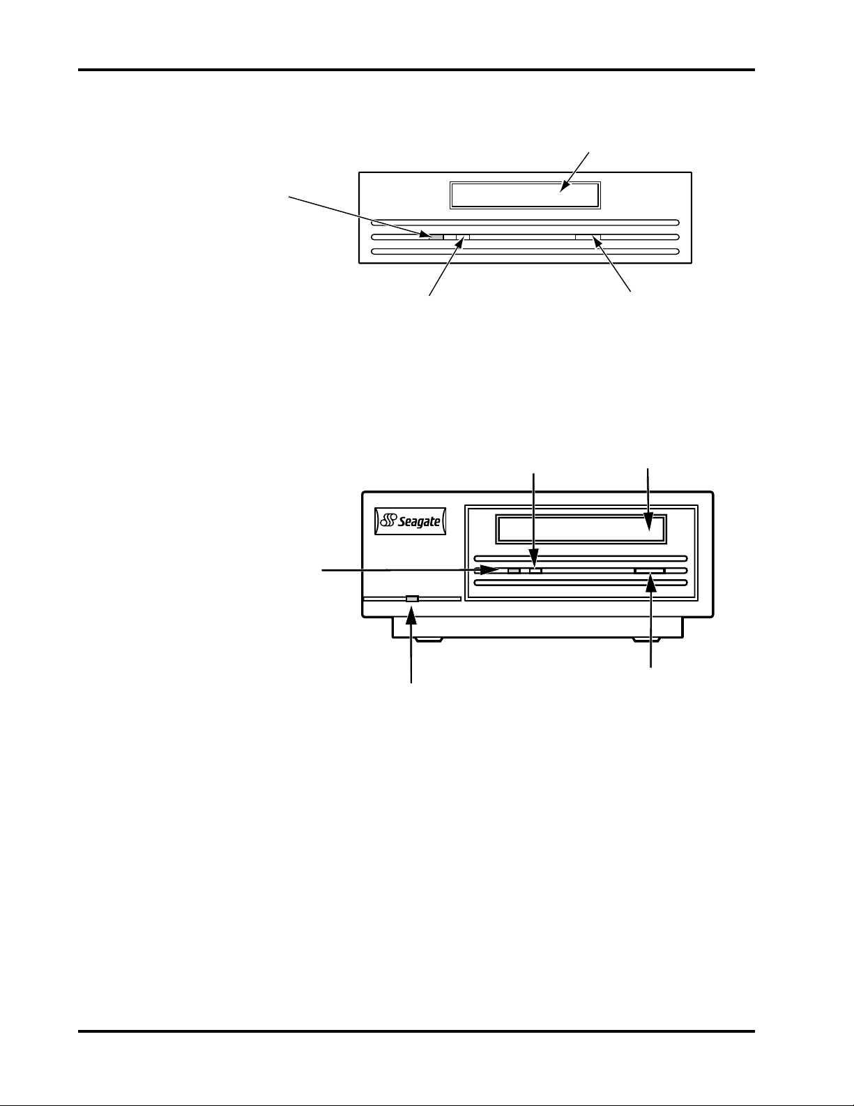
Chapter 4 Drive Operations
Cassette Insertion Slot
Cassette
in Place (Green)
Drive Busy (Yellow)
Figure 18. Front Panel—Internal Model with Rails
Drive Busy
(Yellow)
Cassette in Place
(Green)
Power On
(Green)
Eject Button
Cassette
Insertion Slot
Cassette Insertion Slot
Eject Button
Figure 19. Front Panel—External Subsystem
Page 36 DAT Drives
Page 49

Drive Operations Chapter 4
Loading/Unloading the Cartridge
The cartridge insertion slot on the front panel of the Scorpion 24 drive provides easy
access to the drive.
This section explains loading and unloading a cartridge under normal operating
conditions. It also explains the manual procedure for removing a cartridge
abnormally lodged in the drive. Under a few exceptional conditions—such as a
power outage, you may need to manually unload a cartridge.
Loading/Unloading a Cartridge (Normal Operation)
The Scorpion 24 drive has a front-loading cartridge insertion mechanism that allows
an operator to easily load the cartridge. Insert the cartridge with the arrow on the top
of the cartridge entering the slot first. Push against the middle part of the cartridge
opening until it is fully recessed into the cartridge insertion slot.
Figure 20 illustrates cartridge loading (internal drive shown).
Figure 20. Cartridge Loading (Internal DAT Drive)
Unload the cartridge by pressing the eject (tape unloading) button on the front panel.
(See Figures 17, 18 and 19 for the location of the Scorpion 24 eject button.)
After you press the eject button, the drive updates the system log, rewinds the tape
and then ejects the cartridge. You can then easily remove it from the drive.
The time between pressing the eject button and cartridge ejection may be
Note.
several seconds. Do not power down the external drive or the internal drive
host computer until the unload operation has completed and the cartridge
has fully ejected. Powering down before completion may interfere with the
system log update or may render the tape unreadable.
Product Manual Page 37
Page 50
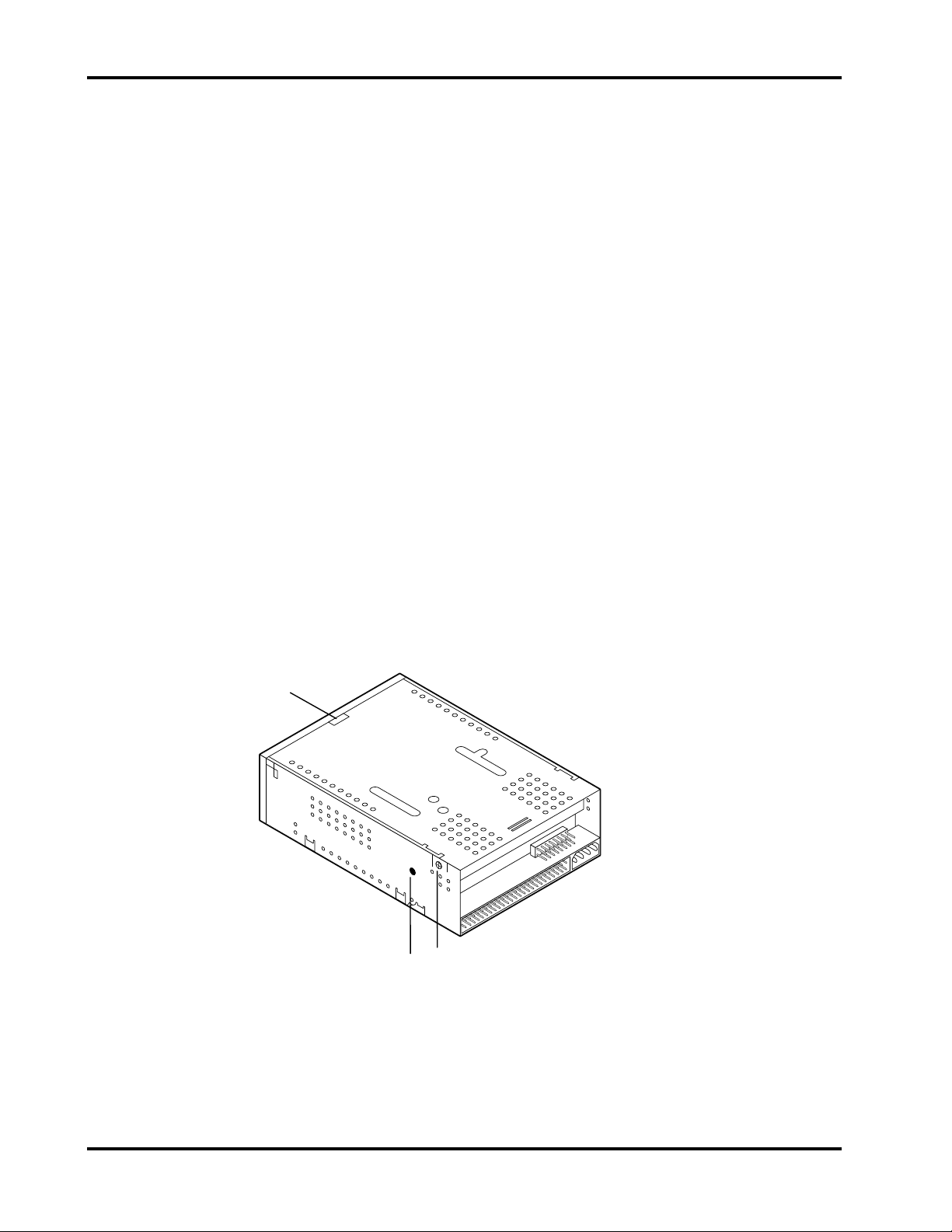
Chapter 4 Drive Operations
Unloading a Cartridge (Manual Operation)
If a power outage occurs while a cartridge is loaded or the automatic unload
procedure previously explained fails, you may want to manually unload a cartridge
from the drive. The following steps outline the manual cartridge unloading and
removal procedure.
1. Remove the power connections. For internal models, disconnect the power
connection with the host computer. For the external model, remove the power
cord from the drive.
2. Disconnect the SCSI cable from the unit.
3. For internal models, remove the drive from the computer.
4. Remove the top cover by removing the two screws at the top edge near the
rear of the unit (one on each side). (See A in Figure 21.) Save the screws in a
safe place. Then remove the front bezel by pulling out on the top of the bezel at
the indentation. (See B in Figure 21.)
For the internal model with rails, remove the mounting rails by removing the
four screws near the lower edge of the unit (two on each side) that are
accessed through holes in the side of each rail. Next, remove the drive’s top
cover by removing the two screws at the top edge near the rear of the drive
(one on each side). Save the screws in a safe place. (See A in Figure 21.)
Then remove the front bezel by pulling out on the top of the bezel at the
indentation. (See B in Figure 21.)
B
A
C
Figure 21. Locations on Drive
Page 38 DAT Drives
Page 51

Drive Operations Chapter 4
5. Turn the unit upside down and remove the four screws (two screws on each
side) that attach the external cover to the chassis unit. Remove the exterior
cover and retain the screws. On the drive unit inside the chassis, remove the
top cover by removing the two screws at the top edge near the rear of the unit
(one on each side). (See A in Figure 21.)
6. Insert a small (precision) screw driver in the hole on the right side of the drive
near the rear and turn the mode motor shaft clockwise. (See C in Figure 21.)
!
Caution. Do
the shaft counterclockwise may damage the mode gear.
Continue turning the mode motor shaft. As you turn the shaft clockwise, you
can see the cartridge slowly rise. The metal track slowly moves forward,
changing the cartridge position as you continue turning the shaft clockwise.
Continue turning the shaft until the cartridge rises and then protrudes from the
slot and “clicks” free. Remove the cartridge.
7. Replace the drive’s top cover and secure it with the two screws that you
removed.
not
turn the mode motor shaft counterclockwise. Turning
8. For internal models, replace the front bezel (internal models) by angling the two
plastic feet at the bottom of the bezel inward and aligning them with the two
holes on the bottom of the unit. Then snap the top of the bezel into place.
For the internal model with rails, reattach the rails using the screws that you
removed.
For the external model, reassemble the exterior cover.
9. Reinstall internal models in the computer and complete all connections.
Reconnect the external model to the computer.
Using a Blank Cartridge
When you insert a blank tape cartridge into the drive for the first time, it is
automatically initialized. The drive first detects that the tape is blank and then
initializes the tape when it receives a command that initiates a write operation.
Note. Initializing the tape takes about 30 seconds. Ejecting the cartridge before the
initialization is complete causes the procedure to abort. The initialization then
restarts from the beginning the next time a Write command is received.
The following steps outline a typical sequence for using a blank cartridge.
1. Gently push the blank cartridge into the cartridge insertion slot on the front
panel with the arrow on the top side of the cartridge entering the opening first.
(See Figure 20.)
Product Manual Page 39
Page 52

Chapter 4 Drive Operations
After the cartridge is partially inserted, the drive mechanism automatically
completes the cartridge insertion process and properly positions the tape within
the drive.
The yellow and green rectangular LEDs on the front panel turn ON as the drive
checks the cartridge to determine its state (blank, write-protected, prerecorded
audio, firmware update, etc.) and then positions to the data area, which typically
takes about 10–12 seconds.
2. Start the software application and issue a command.
For example, if you want to back up a file, issue the appropriate command or
make the appropriate menu selections from the backup application software.
The drive begins initializing the tape before completing the backup (WRITE)
operation.
3. After completing the backup and the yellow rectangular LED on the front panel
is OFF, push the eject (tape unload) button on the front panel to remove the
cartridge.
The drive buffer then empties to tape, the tape rewinds and the system log is
updated.
After being ejected, the cartridge rests in the cartridge insertion slot in a halfway position for easy removal.
Using a Cartridge Containing Data
The sequence for writing a cartridge that already contains data is virtually the same
as the blank cartridge sequence with the exception that the cartridge initialization
process is not necessary.
A brief delay occurs as the cartridge is inserted while the drive identifies the
cartridge type and state, and then positions to the data area.
Loading Revised Firmware Using Seagate Firmware Cartridges
Flash Memory
Another technological advancement incorporated into the Scorpion 24 drive is flash
memory, which is useful if the drive’s SCSI firmware needs to be upgraded. With the
permanently installed, electrically upgradeable flash memory, revised SCSI firmware
for the drive can be loaded using any one of three methods: 1) Seagate OEM
firmware cartridges (see Chapter 4); 2) through the host SCSI bus; and 3) through
the drive serial port (see Chapter 8).
The flash memory feature enables qualified OEMs who need to revise Scorpion 24
SCSI firmware to do so quickly and easily. Flash memory also prolongs the life cycle
of a drive because many new techniques—such as increasing the capacity of the
drive through support for longer tapes—may require only a firmware upgrade.
Page 40 DAT Drives
Page 53

Drive Operations Chapter 4
Firmware Download Process
To load a firmware upgrade tape, follow these steps.
1. Power on the host system with the Scorpion 24 drive installed.
2. Make sure that there are no applications running that may try to communicate
to the drive during the firmware upgrade process. Close any such applications
before inserting the firmware upgrade cartridge.
3. Insert the firmware upgrade cartridge.
!
Caution. Once the firmware upgrade cartridge is inserted into the drive,
it is important that no power interruption occurs while the
firmware is loading.
power interruption occurs, the firmware may not be loaded
correctly, and the drive may not operate properly.
4. The drive automatically recognizes the firmware upgrade cartridge and begins
downloading the firmware from the cartridge into DRAM.
Do not power off the drive
. If a
5. The drive ejects the firmware upgrade cartridge as soon as the firmware has
been completely downloaded into DRAM and the LEDs begin blinking with a
progressive pattern. When the blinking pattern stops, the firmware upgrade
operation is complete.
!
Caution. Do not power down the host system or disconnect power to
the drive until you have completed step 6—this may render
the drive inoperative.
6. Power down the system and reboot. The new firmware is immediately active
and operational.
Note. At this time, we recommend that you power cycle the drive to refresh any
new parameter information and to execute the power-on self-test (POST) to
ensure proper unit functionality.
Firmware upgrade cartridges are available only to qualified Seagate OEM
customers. Contact your Seagate sales representative for information.
Product Manual Page 41
Page 54

Chapter 4 Drive Operations
Page 42 DAT Drives
Page 55

SCSI Interface
5
Introduction
Scorpion 24 drives feature a single-ended SCSI-2 interface. Scorpion 24’s SCSI-2
interface allows for communication between the host computer and the Scorpion 24
drive. The Scorpion 24 SCSI-2 interface conforms to requirements outlined in ANSI
X3.131, 199
This chapter summarizes the SCSI-2 message codes, status codes and commands.
Refer to chapter 3 for specific SCSI cabling and connection information.
x
.
SCSI-2 Interface
Refer to
Seagate’s DAT Tape Drive and Autoloader SCSI Manual
10002663-00
x
) for detailed developer information relative to SCSI implementation.
(part number
The SCSI-2 interface for the Scorpion 24 drive conforms with the ANSI X3.131 1994
standard. The following three tables list the message codes, status codes and
commands for this interface.
SCSI Message Codes
Code Description Direction
00
02
04
05
06
07
08
0A
0B
0C
80
C0
01
H
H
H
H
H
H
H
H
H
H
H
H
2
H
Command Complete In
Save Data Pointer In
Disconnect In
Initiator Detected Error Out
Abort Out
Message Reject In/Out
No Operation Out
Linked Command Complete In
Linked Command Complete with Flag In
Bus Device Reset Out
Identify (No Disconnect/Reconnect) In/Out
Identify (Disconnect/Reconnect) In/Out
Extended Message In/Out
1
1. Direction: In = Drive to host; Out = Host to Drive
2. Supports only one extended message: Synchronous Data Transfer Request
Product Manual Page 43
Page 56

Chapter 5 SCSI Interface
SCSI Status Codes
4-bit Status Code
Bits 4 3 2 1 0 Definition
0 0 0 0 X Good Status
0 0 0 1 X Check Condition
0 1 0 0 X Busy
1 0 0 0 X Intermediate Status
1 1 0 0 X Reservation Conflict
SCSI Commands
Code Type Command
00
01
02
03
05
08
0A
0C
10
11
12
13
15
16
17
19
1A
1B
1C
1D
1E
2B
34
3B
3C
40
4C
4D
H
H
H
H
H
H
H
H
H
H
H
H
H
H
H
H
H
H
H
H
H
H
H
H
H
H
H
H
M Test Unit Ready
M Rewind
V Request Block Address
M Request Sense
M Read Block Limits
M Read
M Write
V Seek Block
M Write Filemarks
M Space
M Inquiry
O Verify
M Mode Select
M Reserve Unit
M Release Unit
M Erase
M Mode Sense
O Load/Unload
O Receive Diagnostic Results
M Send Diagnostic
O Prevent/Allow Medium Removal
O Locate
O Read Position
O Write Data Buffer
O Read Data Buffer
O Change Definition
O Log Select
O Log Sense
M = Mandatory Command O = Optional Command
E = Extended Command V = Vendor-Unique Command
Page 44 DAT Drives
Page 57

SCSI Interface Chapter 5
ANSI X3.131, 199x Conformance Statement (SCSI-2)
General Features
z
Disconnect/reconnect, arbitration (required in SCSI-2)
z
Single-ended drivers
z
Termination power supplied to cable (jumper option)
z
Supports both single and multi-initiator systems
z
Fixed and variable block transfer lengths
z
Hard reset
z
Synchronous data transfers
z
Parity implemented (switch option)
z
Space blocks, filemarks and EOD
z
Supports third-party reservation
z
Log Sense and Log Select for managing soft error reporting
z
MODE SENSE/SELECT page to control and report operation of data
compression in sequential access devices and to read from and write to the
configuration EEPROM
Product Manual Page 45
Page 58

Chapter 5 SCSI Interface
Typical System Configurations
The SCSI standard provides support for up to eight SCSI addresses or IDs. These
IDs refer to host adapters or peripheral devices such as printers, magnetic discs or
tape drives.
Any combination of a single host and up to seven additional SCSI devices can be
chained together on a single SCSI cable.
Figure 22 shows a variety of possible SCSI system configurations.
Computer
System
Host
Adapter
Single Initiator–Single Target
Computer
System
Host
Adapter
Single Initiator–Multiple Target
Computer
System
Host
Adapter
SCSI Bus
SCSI Bus
SCSI Bus
Drive
Drive
Magnetic
Disc,
Printer or
Optical
Discs
Drive
Magnetic
Disc,
Printer or
Optical
Discs
Magnetic
Disc,
Printer or
Optical
Discs
Magnetic
Computer
System
Host
Adapter
Disc,
Printer or
Optical
Discs
Multiple Initiator–Multiple Target
Figure 22. SCSI System Sample Configurations
Page 46 DAT Drives
Page 59

DDS-3 Tape Format
6
Introduction to DDS Recording Format Standards
One of the major benefits in DDS technology is in the consistency and strength of
the format standards.
Precise recording format standards provide the basis for well-defined interchange
requirements. DDS format standards define physical cartridge case requirements,
physical and electrical requirements for the unrecorded tape, format requirements
for tape interchange, measurement methods, and test-environment definition and
provide measurable conformance requirements. With this common technical basis
for interchange, vendors can pursue additional technical features or solutions to
differentiate themselves in the market.
The strong standards associated with DDS technology encourage multiple drive and
media vendors worldwide to participate in the technology. Their participation
provides the end-user with a wide range of choices for high-capacity, highperformance data storage.
While each of the DDS formats has a unique physical and logical format structure,
the purpose of this chapter is to describe the DDS-3 format.
DDS-3 Tape Format
The smallest collection of data supported by the DDS-3 format is a
is the smallest discrete collection of data that can be supplied by the host to the
Scorpion 24 drive for processing and recording to tape. Conversely, a record also
refers to the smallest collection of data readable by the tape drive from tape, for
reprocessing and transfer back to the host system.
Two types of records are supported:
A record may contain processed records, unprocessed records or both. A record
may also contain
Note. Separator marks as described in the DDS-3 standard are similar to the terms
record
. A record
processed records
separator marks
set mark and file mark as used in other recording format standards. Typically
separator 1s refer to file marks and separator 2s refer to set marks.
.
and
unprocessed records.
Product Manual Page 47
Page 60

Chapter 6 Tape Formats
Entities
Entities, unprocessed records and separator marks are collected into
Groups are processed through a series of transformations including randomizing,
interleaving, blocking, generating and inclusion of ECC, and translation of data bytes
to channel bits before recording to tape.
Each group is recorded on a set of
associated information are recorded in the
content, track location and track content information is recorded in the headers of
fragments, which are in the main data zone.
are defined as logical objects that contain processed records.
tracks
. User data, separator marks and
main data zone
of each track. Group
groups
.
Basic Groups
Data from the host system to be recorded to tape is grouped into
384,296 bytes each. For location purposes on the tape, each individual basic group
is identified by a number beginning at 0, running consecutively thereafter. Within
each basic group, the individual bytes are also identified, again with a consecutively
running number beginning at 1 and running through 384,296.
Data and separator marks transferred from the host system are grouped into an
individual basic group according to the following structure:
basic groups
of
Byte No.
1, 2, 3, .
. .
Entities or
Unprocessed
Records
. . . 384,261
Block
Access
Table
384,262
384,296
Group
Information
Table
35 bytes
384,296 bytes
Figure 23. Structure of a Basic Group
As seen in Figure 23, in addition to entities or unprocessed records, the structure of
a basic group includes a
(BAT)
. The group information table always occupies the last 35 bytes of the basic
group.
group information table (GIT)
and a
block access table
Page 48 DAT Drives
Page 61

Tape Formats Chapter 6
Entities
Each entity includes an entity header and a processed record sequence. The
header is 8 bytes long and precedes the processed record sequence. By definition,
all processed records contained within an entity go through the same processing
algorithm; additionally this processing takes place only on unprocessed records of
equal length.
Entities can span basic groups as long as the header and the first 8 bits of the
processed record sequence are within the same basic group. Where an entity has
spanned multiple basic groups, the individual parts of the entity within the basic
groups are referred to as
partial entities
.
Subgroups
When the formation of a basic group is complete, the next step is to split the basic
group into 22
G1 subgroup is assigned a consecutive number from 1 through 22.
G1 subgroups
of 17,468 bytes numbered from 0 through 17,467. Each
The bytes of each G1 subgroup are then randomized to form a
equal size.
Each
G2 subgroup
first 8,734 bytes are grouped into Track A of the G3 subgroup; the remaining 8,734
bytes are grouped into Track B of the same G3 subgroup.
Finally, each G3 subgroup is transformed into a
sign, a fragment number and a serial number. Each G4 subgroup consists of two
arrays of 96 fragments each. Each fragment is transformed into a
fragment
number, subcode bytes and fragment header parity bytes.
. Each main data fragment consists of a fragment ID, an area ID, a frame
is then rearranged to form a G3 subgroup of 17,472 bytes. The
G4 subgroup
G2 subgroup
that contains an array
main data
of
Basic Group Transformation Summary
Through the transformation process described above, each basic group is
transformed into 4,224 main data fragments before recording to tape.
Subcode Information
Subcode information
separator 1s written since the logical beginning of tape (LBOT), the number of
separator 2s written since the LBOT, the number of records written since the LBOT
information about track contents and information about the history of the tape.
specifies the running number of the basic group, the number of
Subcode Location
Subcode information is written within each main data fragment header.
Product Manual Page 49
Page 62

Chapter 6 Tape Formats
DDS-3 Track Geometry
The Scorpion 24 DDS-3 drive records to tape in a helical track pattern. This track
pattern is dependent upon the relationship of two items: 1) the direction of tape
motion and 2) the rotational axis of a pair of record heads located on the tape drive
cylinder. One recording head has a positive azimuth angle and the other has a
negative azimuth angle. (Chapter 8 of this manual,
explains details relative to helical scan recording and the head to tape interface.)
The direction of tape recording is away from the
Theory of Operations
tape reference edge
Direction of tape motion
, further
.
Postive-azimuth track
Tape reference edge
Legend:
A – Tape width
B – Ideal tape centerline
θ – Track angle
L
Negative-azimuth track
T
Positive
azimuth angle
Direction of head motion
P
θ
Negative
azimuth angle
L – Track length
P – Track pitch
T – Track width
A
B
Figure 24. Track Configuration
Page 50 DAT Drives
Page 63

Tape Formats Chapter 6
DDS-3 Track Specifications
Parameter Specification
Average Track Pitch
Variations of Track Pitch 2% maximum
Track Width
Nominal
Measured
Track Angle
Track Length
Ideal Centerline 1.900 mm from the
Azimuth Angle
Positive
Negative
9.053 µm ± 0.045 µm
9.053 µm
9.1 µm ± 1.8 µm
6° 22' 39.6"
23.521 mm ± 0.047 mm
Tape Reference Edge
20° 00' 39.6" ± 15' 00.0"
19° 59' 20.4" ± 15' 00.0"
Recorded Patterns
The host data, which has already been transformed as described in the subgroup
section above and is contained within the main data fragments, is translated into
channel bits for recording to tape. The DDS-3 format specifies that each 8-bit byte
of the data found in the main data fragments is translated into a 10-bit pattern.
These 10-bit patterns are referred to as channel bits.
Format of a Track
Each individual track is made up of two
margin zones
data zone.
Track Format
Zone Contents Number of 10-bit Patterns
Margin Zone No. 1 Margin Pattern 640
Preamble Zone Preamble Pattern 64
Main Data Zone Recorded Main Data Fragments 12,768
Margin Zone No. 2 Margin Pattern 640
, a
preamble zone
and a
main
Product Manual Page 51
Page 64

Chapter 6 Tape Formats
Positioning Accuracy
The DDS-3 specification reflects a tighter requirement for
compared to previous standards.
The DDS-3 standard specifies the position reference point of all tracks to be 1.906
mm from the tape reference edge.
The position reference point of any adjacent 12 tracks, or positional reference point
variance, must be within 1.0 µm of the mean position reference point of all tracks
within the described continuum.
This compares to a position reference point variance of 6.6 µm as allowed in the
DDS-2 format standard.
positioning accuracy
when
Timing Tracking
Playback tracking in the previous DDS-2 and DDS formats was accomplished
through the use of
special low frequency tracking signals be recorded at both ends of each data track
recorded to tape. The ATF method reduced overall format efficiency and also
required special analog hardware circuitry to read and process these ATF signals.
The DDS-3 format departs from the ATF method, using instead, a more
sophisticated
tape. timing tracking control is performed within the firmware by calculating the
elapsed time from a fixed point in the rotational arc of the head cylinder to a
reference point (sync signal or parity signal) recorded within the track area.
Advantages of the timing tracking include a 50 percent increase in format efficiency
over DDS-2, more accurate tracking due to separate tracking error calculations for
each record head and more flexible tracking because tracking can be performed
using data detected anywhere along the length of the track.
automatic track following (ATF).
timing tracking
system to ensure accurate tracking throughout the
The ATF method required that
With timing tracking, capstan servo control is performed by monitoring the time from
the cylinder PG signal until the recorded track data begins; that is, until the first sync
or parity data is detected.
When the playback head is perfectly on track, this time is measured as T0. When
the head is off track by any amount, the measured time T1 is longer or shorter than
T0, depending on whether the tape is moving too fast or too slow. The capstan
servo can then use this time difference to correct the tape speed and to bring the
heads back on track.
Page 52 DAT Drives
Page 65

Tape Formats Chapter 6
Subcode
Active track
Case 1: The head is off track because the tape is moving too fast.
Too much time elapses before the heads read the subcode.
To bring the heads on track, the drive automatically slows the tape.
Case 2: The head is on track, and no corrective action is necessary.
Case 3: The head is off track because the tape speed is too slow.
Too little time elapses before the heads read the subcode.
To bring the heads on track, the drive automatically increases
the tape speed.
Figure 25. Timing Tracking
Read Head
The PG position is a known constant which is based on the fixed mechanical
positions of the PG sensors and the heads within the cylinder. These relative
positions do not change and can be used as a solid baseline for the timing
calculations. Also, because there are separate PG pulses associated with each
recording head (A and B), accurate timing tracking can be achieved even under
adverse conditions.
To ensure optimum accuracy, a calibration is performed whenever a recorded tape
is inserted into the Scorpion 24. This calibration determines the target time against
which all succeeding measurements are compared.
Tape Layouts in the DDS-3 Standard
The DDS-3 standard provides for two types of overall tape layouts, single data
space tapes and partitioned tapes. The following two sections describe the specific
layouts for each.
Layout of a Single Data Space Tape (Single Partition)
The DDS-3 recording format supports both
and
partitioned tape
. You can record a tape as either a single data space tape or as
a partitioned tape.
The tape layout f or a s ingle data space tape cont ains s ix ar eas : the
the
reference area,
the
system area,
the
area.
single data space tape (nonpartitioned)
device area,
data area,
the
EOD area
and the
post-EOD
Product Manual Page 53
Page 66
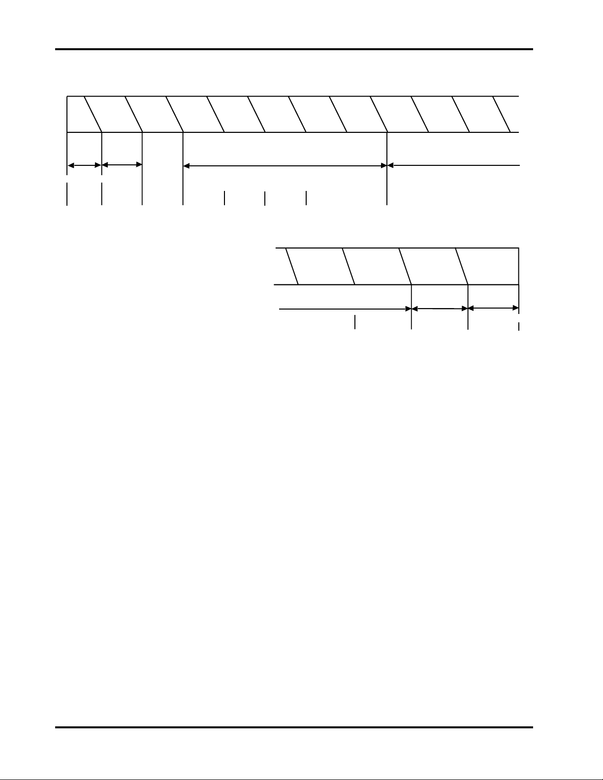
Chapter 6 Tape Formats
Device
Area
Reference
Area
Pos. Tol.
Band
No. 1
System
Preamble
System
Log
System
Postamble
Pos. Tol.
Band
No. 2
Vendor
Group
Preamble
Vendor
Group
Recorded
Data Group
No. 1
Recorded
Data Group
No. 2
Device
PBOT
350 mm
±10 mm
Reference
LBOT
35
frames
System
30
frames
25
frames
10
frames
Data
Post-EOD
Area
EOD
Area
Amble
Frames
Last
Recorded
Data Group
Post-EOD
EOD
Minimum
450 frames
Data
Minimum
12 frames
PEOT
Figure 26.Layout of a Single Data Space Tape
Device Area
The device area is the first area recorded on the tape and extends from the physical
beginning of tape (PBOT) to the logical beginning of tape (LBOT). The device area
is not used for writing data for interchange. The device area consists of three zones,
the
spinup zone
, the
test zone
and the
guard zone
.
The spinup zone consists of the first part of the tape that is wrapped around the
cylinder when the tape is inserted into the drive. The next zone, the test zone, is
available for read/write purposes. The last zone, the guard zone, is specified as
having a minimum length of 9 mm in which no recording is permitted.
Reference Area
The Reference Area is used as the physical reference when updating the
and consists of 35
absolute frame number
tape management frames
of 1.
starting at the LBOT and having an
Page 54 DAT Drives
system log
Page 67
Tape Formats Chapter 6
System Area
The System Area consists of the
postamble, position tolerance band 2
system preamble
and the
vendor group preamble
, the
system log
, the
.
system
Data Area
The data area consists of the
groups
. The vendor group is defined as basic group 0 (refer to the basic broup and
subgroup information above). Each recorded data group is equivalent to a single
basic group.
To ensure the highest possible data integrity, two methods are used.
First, the Scorpion 24 creates ECC3 (error-correction code 3) data, which provides
the capability to correct any two bad tracks in a recorded data group. The ECC3
data is derived from the 22 G1 subgroups of each basic group to form a 23
subgroup.
Second, to guard against normal expected tape defects, the Scorpion 24 uses readafter-write capability to identify frames that have not been recorded correctly to tape
(read-after-write is described in detail in Chapter 8, “Theory of Operations”, on page
71). When the drive identifies an incorrectly recorded frame, it is rewritten within a
maximum of 7 frames further down the tape. To skip elongated sections of defective
spots on tape, the rewrite operation may be repeated up to 255 times.
vendor group
and one or multiple
recorded data
rd
G1
Appending to Tape
The DDS-3 format provides for
tape.
1 Frame
A
Frame Number:
Figure 27. Appending Rules
n
seamless appends
m
Amble Frames
m
‡ 1
B
n + 2
and
nonseamless appends
C
n + 3 + m
to
Product Manual Page 55
Page 68

Chapter 6 Tape Formats
The following rules are for the DDS-3 format for a seamless append:
1. There should be one frame between Frame A and Frame B. For example, if
frame A has an absolute frame number (AFN) of
an AFN of
2. The frame written between Frames A and B should be contiguous with Frame
A. For example, no unrecorded space between A and B is permitted.
3. There should be a minimum of one amble frame between Frames B and C. For
example, if Frame B has an AFN of
n + 4
discontinuity or repetition is allowed between frames B and C.
n + 2
.
n + 2
, then Frame C should have an AFN of
minimum. No unrecorded space, physical discontinuity or AFN
n
, then Frame B should have
Frame A
(AFN =
n
)
Frame
(AFN =
n
+ 1)
Frame B
(AFN =
n
+ 2)
Direction of tape motion
Ideal tape
centerline
Tape reference edge
X
Figure 28. Tolerance on Seamless Appending
The following rules are for the DDS-3 format for a nonseamless append:
1. The distance between Frame A and Frame B should allow for a minimum of one
and a maximum of 11 frames. No unrecorded space is allowed between Frame
A and Frame B.
2. Discontinuities and repetitions of AFN are permitted between Frame A and
Frame B provided that, where Frame A has an AFN of
n,
– All frames have an AFN greater than
n + 2
– Frame B has an AFN of
Page 56 DAT Drives
minimum and
and
n + 12
n
,
maximum.
Page 69

Tape Formats Chapter 6
3. Amble frames between Frame A and Frame B should have a value of group
number that is equal to that of Frame A. Other frames between Frame A and
Frame B should have a value of group number that is greater than that of
Frame A.
4. There should be a minimum of 29 frames between Frames B and C. For
example, if Frame B has an AFN of
have an AFN of
or seam or AFN discontinuity or repetition is allowed between Frames B and C.
n' + 30
minimum. No unrecorded space, physical discontinuity
n + 2
≤ n' ≤
n + 12
, then Frame C should
EOD Area
The data area is always followed by an
exist on tape, but the EOD area closest to LBOT is the only valid one for information
interchange. The EOD area is also followed by a
EOD area
. More than one EOD area can
post-EOD area
that extends to the
physical end of tape (PEOT).
Early Warning Point (EWP)
The
early warning point (EWP)
host that the PEOT is being approached. Any data transfer operation currently
underway should be completed, the data should be recorded to tape and no more
data transfers occur until a new cartridge is loaded.
In the case of a new or unwritten tape, the EWP is calculated by the drive based on
a number of factors including tape cartridge type (which automatically renders a
media length factor) and is then held in memory. By specification, the EWP is
always a minimum of 3 mm before the PEOT. If data is recorded beyond the
calculated EWP, the after early warning point (AWEP) bit is set on the last basic
group completely or partially recorded before that point. The AWEP now denotes
the position of the EWP the next time that the tape is read. In addition, this
information is also recorded into the system log as part of the update of the tape
history before unloading the tape.
For a tape that contains data, but which is being overwritten, the drive follows the
same procedure as with a new or unwritten tape. The drive calculates the EWP,
ensuring that the calculated EWP is not less than 3 mm before the PEOT. If data is
written beyond the EWP, the AWEP bit is set on the last basic group completely or
partially recorded before that point. The AEWP now represents the position of the
EWP for the next read. The system log is also updated at unload time to reflect this.
functions as an alert from the DDS-3 drive to the
Initialization
Initialization
the first time. The reference area, system area and the vendor group are all
recorded per DDS-3 standard requirements in preparation for recording of the first
recorded data group to tape.
Performing the Initialization step on a previously recorded tape effectively destroys
all data contained on the tape, including that found in the reference area, system
area and in the vendor group.
Product Manual Page 57
refers to the process of preparing the tape for recording user data for
Page 70

Chapter 6 Tape Formats
Device
Area
Reference
Area
Pos. Tol.
Band
No. 1
System
Preamble
System
Log
System
Postamble
Pos. Tol.
Band
No. 2
Vendor
Group
Preamble
Vendor
Group
Recorded
Data Group
No. 1
Recorded
Data Group
No. 2
Device
PBOT
350 mm
±10 mm
Reference
LBOT
35
frames
System
30
frames
25
frames
10
frames
Data
Last
Recorded
Data Group
Amble
Frames
EOD
Area
Post-EOD
Area
450 EOD
Frames
Reference
Area
Pos. Tol.
Band
No. 1
System
Preamble
System
Log
System
Postamble
Pos. Tol.
Band
No. 2
Partition No. 1
Partition No. 1
Partition No. 0
Data
Min. 12
frames
EOD
Min. 450
frames
Post-EOD
VEOT LBOT
Reference
System
30
frames
25
frames
10
frames
Vendor
Group
Preamble
Vendor
Group
Recorded
Data Group
No. 1
Recorded
Data Group
No. 2
Last
Recorded
Data Group
Amble
Frames
Post-EOD
Area
System
Data
EOD
Min. 450
frames
Min. 12
frames
Partition No. 0
PostEOD
EOD
Area
Layout of a Partitioned Tape
A
partitioned tape
effectively two single data space tapes on one tape cartridge. Each of the two
partitions have the similar structure and properties to those of a single data space
tape.
provides the end-user with two independent partitions, or
Figure 29. Layout of a Partitioned Tape
Page 58 DAT Drives
Each partitioned tape’s layout consists of a device area,
Partition 1
located in order from PBOT to PEOT.
The device area is identical to that of a single data space tape.
and
Partition 0,
Page 71

Tape Formats Chapter 6
Partition 1
The total number of frames in Partition 1 is recorded in the system log of Partition 1.
virtual end of tape (VEOT)
The
is a reference point for Partition 1, the same as the
PEOT on a single data space tape. The VEOT is found 450 frames before the
partition boundary.
The
Partition 1 early warning point (EWP)
functions the same as the EWP for a
single data space tape except that the EWP is not less than 3,067 frames
(approximately 500 mm) before the VEOT.
Partition 1’s Data Area is followed by the
Partition 1 EOD Area
. The EOD Area can
be up to 450 frames in length and consist of tape-management frames, beginning
after the last amble in the sequence of amble frames following the last recorded
data group.
In the event that the end of the EOD area occurs before the VEOT, it is followed by
a
post-EOD area
extending to VEOT.
Partition 0
Immediately following Partition 1’s VEOT, and after Partition 1’s EOD frames,
Partition 0 begins with its LBOT. The LBOT is the partition boundary. The first frame
after this point has the absolute frame number (AFN) of 1.
The composition of Partition 0 is virtually the same as Partition 1.
Initialization of Partitioned Tapes
If a new or bulk-erased tape is used as a partitioned tape, we recommend that you
perform an initialization pass first. Given the fact that the user data may only fill one
partition, leaving the other empty, the initialization process ensures that the partition
boundary is correctly set, and Partition 1 and Partition 0 are both set up correctly
during the first write pass.
By definition, an
z
A reference area
z
A system area
z
A data area, comprising a vendor group and at least 35 amble frames
z
A minimum of 3,517 tape-management frames identical to those of the EOD
area of Partition 1.
The vendor group preamble, the data area and the subsequent tape-management
frames all form a continuum extending to the partition boundary. No unrecorded
space, physical discontinuity, seam, absolute frame number discontinuity or
absolute frame number repetition is permitted.
Empty Partition 1
consists of:
Product Manual Page 59
Page 72

Chapter 6 Tape Formats
An
Empty Partition 0
z
A reference area
z
A system area
z
A data area, comprising a vendor group and at least 35 amble frames
z
An EOD area 450 frames in length at a minimum.
consists of:
The vendor group preamble, the data area and the EOD area all form a continuum.
No unrecorded space, physical discontinuity, seam, absolute frame number
discontinuity or absolute frame number repetition is permitted.
Housekeeping Frames
Housekeeping frames
housekeeping frames:
do not include user data. There are three types of
amble frames, system log frames
frames.
Specific rules govern where and how these frames are recorded. Please refer to the
DDS-3 standard for these rules.
DDS-3 Recording Format Standard—Further Reference
For more information about the DDS-3 Recording Format Standard, refer to ECMA236,
3.81mm Wide Magnetic Tape Cartridge for Information Interchange - Helical
Scan - DDS-3 Format using 125m Length Tapes
A copy of the standard can be obtained by contacting ECMA at:
Phone: 41-21-849-60-00
FAX: 41-22-849-60-01
URL: http://www.ecma.ch
Internet: helpdesk@ecma.ch
and
tape management
.
Page 60 DAT Drives
Page 73

Data Compression
7
Introduction
Data Compression—General
Typical data streams of text, graphics, software code or other forms of data contain
repeated information of some sort, whether it is at the text level where you can
readily recognize regular repetitions of a single word or at the binary level where the
repetitions are in bits or bytes. Although most data is unique and random, the binary
level data exhibits patterns of various sizes that repeat with varying degrees of
regularity.
Storage efficiency is increased if the redundancies or repetitions in the data are
removed before the data is recorded to tape. Data compression technology
functions to significantly reduce or eliminate the redundancies in data before
recording the information to tape. This increases the amount of data that can be
stored on a finite medium and increases the overall storage efficiency of the system.
With data compression, the redundant information in a data stream is identified and
then represented by codewords or symbols, which allow the same data to be
recorded in a fewer number of bits. These symbols or codewords point back to the
original data string, using fewer characters to represent the strings. Because these
smaller symbols are substituted for the longer strings of data, more data can be
stored in the same physical space.
Some important benefits result from data compression in DAT drives:
z
The same amount of information can be stored on a smaller length of tape.
z
More data can be stored on a given length of tape.
z
Performance can more closely parallel to that of high-transfer-rate computers.
z
More information can be transferred in the same time interval.
Product Manual Page 61
Page 74

Chapter 7 Data Compression
Data Compression Considerations
In an effective data-compression method, several factors are important:
z
The amount of compression (measured by the
ratio that compares the amount of uncompressed data to the amount of
compressed data and is obtained by dividing the size of the uncompressed data
by the size of the compressed data)
z
The speed with which data is compressed and decompressed in relation to the
host transfer rate
z
The types of data to be compressed
z
The data integrity of the compressed data
The amount of compression possible in a data stream depends on factors such as
the data pattern, the compression algorithm, the pattern repetition length, the
pattern repetition frequency, the object size (block of information to be compressed)
and the starting pattern chosen.
The transfer rate depends on factors such as the compression ratio, the drive buffer
size, the host computer input/output (I/O) speed, the effective disc speeds of the
host computer and the record lengths that the host computer transmits.
compression ratio
, which is a
Data compression algorithms can be tailored to provide maximum compression on
specific types of data. But because varying types of data are encountered in normal
day-to-day operating circumstances, an effective data compression method for a
tape drive must serve various data types. Additionally, the data compression
method must
adapt
to different data types, automatically providing optimum handling
for all types of data.
Considering these factors, Seagate engineers concluded:
The most effective data compression method must compress as much data as
possible under the following conditions:
z
The transfer rate of the host computer is not impeded.
z
Adaptation is made to different types of data.
z
Data integrity is maintained.
Page 62 DAT Drives
Page 75

Data Compression Chapter 7
Hardware Compression
If data compression is used in software on the host computer rather than in the
hardware of the drive, you can slow down the transfer rate of the host because it
must perform compression computations in addition to its regular computations.
Also, any other host that wants to retrieve (decompress) the data must have the
same software.
Hardware data compression (HDC) refers to the implementation of the DCLZ
algorithm in the SCSI/data compression chip onboard the drive, with the
compression processing activity transparent to the host computer and the user.
Seagate’s SCSI/data compression chip is designed to provide a complete data
compression system using the DCLZ algorithm. This chip provides support circuitry
as well as the core DCLZ compression machine.
A more detailed description of the data compression chip is given later in this
chapter.
Data Integrity
There are various types of data-compression algorithms, but in this document they
are divided into two basic types:
lossy
algorithms, such as those used in some consumer audio products.
Lossy algorithms drop out or lose some portion of repetitious data during the
compression process to reduce the actual data bytes that are recorded to tape. The
data lost during this process is lost forever and cannot be recovered. In consumer
audio, this is not a problem because this method reduces required storage space
and still provides better-than-analog recording and playback quality.
As you would expect, lossy algorithms are inappropriate for computer data storage
of any type; hence the choice of lossless algorithms for computer data storage use.
Lossless algorithms are designed to compress data using a complex algorithm,
ensuring that all data is compressed and recorded to tape and that all data can be
decompressed and returned in the identical format as before. No bits are lost, and
no data is compromised.
The DDS standards specify the use of the DCLZ algorithm, a lossless algorithm for
data compression.
lossless
algorithms, such as DCLZ or ALDC, and
Product Manual Page 63
Page 76

Chapter 7 Data Compression
DCLZ Algorithm
DCLZ Algorithm
Within the computer industry, algorithms developed by Abraham Lempel and Jacob
Ziv (enhanced later by Terry Welch) are popular, versatile and powerful
compression methods. These LZ algorithms are basically of two types—LZ1, a
sliding window method, and LZ2/LZW, a hashed directory method.
LZ2
and
LZW
(Lempel-Ziv-Welch) are algorithms based on the
method; these algorithms offer an acceptable compromise between speed and
compression ratio. This type of algorithm builds a symbol dictionary to represent
strings as the data is processed and then looks up matching patterns in the
dictionary. By monitoring the compression ratio in this type of algorithm, a new
dictionary can be started when the ratio drops, indicating a change in the data type.
This type of algorithm is responsive to changing data patterns while maintaining
acceptable speed.
hashed dictionary
Although dependent on the particular implementation, the LZ2/LZW type of
algorithm is generally faster than the LZ1 type because the dictionary structure
promotes efficient searching.
The DCLZ algorithm used in the Scorpion 24 tape drive is based on the LZ2/LZW
algorithm type described earlier in this chapter. This algorithm has been approved
by the US ANSI standards group and the European ECMA standards group. Both
the DDS Manufacturers Group and QIC tape industry-standards committees accept
DCLZ as an approved standard. Within the DDS Manufacturers Group, DCLZ is the
only approved standard, ensuring complete interchange across all DDS drives and
media.
Simplified Compression Operation
The following steps describe a simplified version of operation of the algorithm for
compressing data.
1. From the current position in the input data stream, the algorithm fetches bytes
(characters) until a string is formed that does not have a matching entry in the
dictionary.
2. The codeword for the longest string that has an entry in the dictionary (all bytes
except the last) is output.
3. A dictionary entry for the string formed in step 1 is created.
4. The current position is moved to the last byte of that string.
5. Steps 1 through 4 are repeated until the input data stream is completely
processed.
Page 64 DAT Drives
Page 77

Data Compression Chapter 7
The following table illustrates this simplified operation.
Dictionary
Input
Byte
RR Y — —
I RI N RI (R)
—I Y — —
N IN N IN (I)
—N Y ——
T NT N NT (N)
—T Y ——
I TI N TI (T)
—I Y ——
NIN Y ——
T INT N INT (IN)
—T Y ——
ITI Y ——
N TIN N TIN (TI)
—N Y ——
Current
String
Match
Build
Entry
Output Code
Value
The dictionary is built and contained logically in external RAM and is not output as a
distinct item. Rather, the decompressor recreates the dictionary to recreate the
original data.
The dictionary allows up to 4,096 entries with each entry made up of:
z
The unique string found in the data stream
z
The codeword for that string
Codewords represent strings of up to 128 characters and are formed by adding a
new character to an existing codeword. These codewords range from 9 through 12
bits in size and are assigned a number in the range 0 through 4,095.
These codewords are either control flags, encoded bytes or dictionary codes. The
following points explain these three types of codewords.
z
Control Flags, codewords 0 through 7:
These control flags are reserved
codewords that flag specific conditions as follows:
0 Dictionary frozen
1 Dictionary reset
2 Increment codeword size
3 End of record (EOR)
4–7 Reserved
z
Encoded bytes, codewords 8 through 263:
These encoded bytes represent
single bytes of the input data stream and contain the values 0 through 255.
Product Manual Page 65
Page 78

Chapter 7 Data Compression
Dictionary codes, codewords 264 through 4,095: The dictionary codes refer
z
to dictionary entries and represent multiple bytes (a string of characters) in the
input data stream. These codes are built as the input stream is processed.
These codes are pointers to other locations and eventually end by pointing to
one of the byte values 0 through 255. A linked chain is created that builds up a
string of characters.
Each dictionary entry is 23 bits long and comprises a logical RAM address. The
information is stored in 8-bit-wide static RAM chips that are 8K, 10K, or 16K by 22bits. The structure of each dictionary entry is as follows:
Bits 0 through 7 contain the byte value of the entry.
z
Bits 8 through 19 contain the codeword that represents the entry or that points
z
to a previous entry (encoded byte or dictionary code).
Bits 20 through 22 are condition flag bits.
z
Dictionary codewords range from 9 through 12 bits in length and correspond to
dictionary entries from 0 through 4,095. These entries are divided as follows:
z
First 512 entries are 9-bit codewords.
z
Second 512 entries are 10-bit codewords.
z
Next 1,024 entries are 11-bit codewords.
z
Final 2,048 entries are 12-bit codewords.
Simplified Decompression Operation
The DCLZ algorithm requires that compression and decompression be tied together
through:
z
The compression and decompression processes (requires synchronization)
z
The packing and unpacking of codewords into a byte stream (requires
synchronization)
That is, decompression of the data does not begin at an arbitrary point; rather, it
begins at a point where the dictionary is reset—known to be empty. This stipulation
is vital because the dictionary is embedded in the codewords, which saves time and
space as it is not recorded separately.
Likewise, the packing and unpacking process require synchronization so that the
compressed data is presented to the algorithm in the proper order.
Page 66 DAT Drives
Page 79

Data Compression Chapter 7
The following steps describe a simplified version of the operation of the algorithm for
decompressing data.
1. From a reset dictionary point, (which contains only control codes and encoded
bytes) codewords are fetched from the input stream and looked up in the
dictionary.
2. New dictionary codes are built by combining the previously received codewords.
(The dictionary created during compression is recreated, guaranteeing that any
codeword received is contained in the dictionary.)
Codewords that are encoded bytes are output directly. Codewords that are
dictionary codes lead the algorithm through a series of bytes and codewords that
point to other dictionary entries. Bytes are stacked until an encoded byte occurs;
then, the stack is output.
The following table illustrates the reverse process of compression, showing
simplified decompression operation.
Input
Code
Value
(R) R — Y R — R
(I) I — Y I RI I
(N) N — Y N IN N
(T) T — Y T NT T
(IN) N (I) N N — —
— I — Y NI TI I
(TI) I (T) N I — —
— T — Y IT INT T
——————I
(N) N — Y N TIN N
Byte
Value Pointer Root? LIFO Entry
Output
Byte
The following table shows the dictionary based on the table above and the table on
page 65.
Code Value
Codeword Byte Value
(RI) I (R)
(IN) N (I)
(NT) T (N)
(TI) I (T)
(INT) T (IN)
(TIN) N (TI)
(Pointer)
Product Manual Page 67
Page 80

Chapter 7 Data Compression
SCSI/Data-Compression Chip
Overview
The Seagate SCSI/data-compression chip contains compression and
decompression circuitry, which forms the core of the data-compression system
using the DCLZ algorithm. This core is called the
The DCLZ machine compresses data from the SCSI bus before it is transferred to
the local control bus. When compressing information, data originates from the SCSI
bus and passes through the SCSI core to the DCLZ machine or data-compression
core. However, that interface performs byte operations in the event of an odd block
size.
The Seagate SCSI/data-compression chip used in the Scorpion 24 tape drive
provides the basis for an effective data-compression system using the DCLZ
algorithm. The chip includes a SCSI controller and a data-compression processor
arranged in an inline configuration.
Like other component devices used in these state-of-the-art drives, the SCSI/data
compression chip uses the low-power CMOS technology. The device is packaged in
a 100-pin plastic quad flat pack (PQFP).
DCLZ compression machine
.
Features
The SCSI/data-compression device provides the following features:
z
Integrated SCSI controller
z
Implements DCLZ data-compression algorithm
z
Provides 10.0 Mbyte-per-second maximum throughput for synchronous
operation and 7.0 Mbytes per second for asynchronous operation
z
Compatible with DDS compression standards
z
Provides internal data FIFO
z
Supports data pass-through mode to bypass compression
z
Provides internal SCSI data FIFO
z
Built-in DMA control unit
Page 68 DAT Drives
Page 81
Data Compression Chapter 7
Figure 30 illustrates the layout of the SCSI/data-compression device.
100-Pin PQFP Chip
Data-Compression Core
Compressor
SCSI
Core
SCSI
Host
Interface
Decom-
pressor
External Static RAM
Figure 30. Layout of SCSI/Data Compression Device
8K × 32
Formatter
Micro-
Processor and
DMA Interface
Product Manual Page 69
Page 82

Chapter 7 Data Compression
Page 70 DAT Drives
Page 83

Theory of Operations
8
Overview
The Scorpion 24 tape drive design integrates DAT technology (helical scan
recording method) into a true computer-grade data-storage peripheral with industrystandard data-compression capability.
These drives are the result of:
z
Combining the economies of scale from the audio electronics market for key
components, such as the cylinder, heads and audio LSIs, with a computer
grade drive (3.5-inch) using four direct drive motors, a
mechanism and electronic tape path control for the demanding computer
storage environment.
z
Implementing a four-head design to provide read-after-write (RAW) error
correction and to maximize the benefits of the helical scan recording method,
namely: (1) high-density recording (all tape space is used by dense, overlapping
tracks at alternating azimuth angles) and (2) high-speed searches.
no-mode change
z
Using second-generation audio and custom LSIs for efficient circuit layout and
increased reliability with low power consumption. These LSIs are quad-flat-pack
(QFP) designs that use complementary metal-oxide semiconductor (CMOS)
technology.
z
Implementing the DDS-3 format.
z
Implementing hardware data compression in the drive using the SCSI/datacompression chip.
z
Using flash memory devices for easy firmware upgrades.
z
Storing configuration information in the parameter block of flash memory.
z
Enabling the user to access configuration information in the flash memory using
the SCSI MODE SENSE command and to program the flash memory using the
SCSI MODE SELECT command.
z
Implementing custom C3 ECC coprocessor capabilities and other errorcorrection techniques.
z
Embedding a full-LSI SCSI controller with capability for SCSI-2 command sets
in single-ended SCSI DDS-DC models.
This chapter describes the Scorpion 24 DDS-3 drive in more detail and explains
implementation-specific information.
Product Manual Page 71
Page 84

Chapter 8 Theory of Operations
The STD124000N Drive
The Scorpion 24 uses the helical scan recording method with a four-head cylinder
design. Four direct-drive motors and one brush-type motor are used in the drive.
The read and write functions use LSIs. Engineering decisions—such as the modular
partitioning of the electronics and use of surface mount, low power commercial and
custom LSIs—allow the drives to conform to the industry-accepted 3.5-inch formfactor. These design features are also important contributors to the overall reliability,
durability and performance of the drive.
The Scorpion 24 mechanism is designed for minimum tape wear and prevention of
damage to the tape. The modes or operational states, such as stop, rewind and
play, reduce mechanism and tape wear. Fewer mechanical mode changes result in
less wear on key drive components. In some cases, the need for a mode change is
circumvented using the Pause mode, which stops the tape without activating the
mechanism. All mode selection is performed by the controller firmware. The host
computer does not directly control mode selection.
A custom timing tracking design (described in detail in Chapter 6), combined with
the four-head cylinder design, implements the specifics of the DDS-3 recording
format standard and provides the precision required to perform seamless appends,
or the ability to add subsequent recorded data frames immediately adjacent to the
last data frames written on the tape.
A bank of jumpers is available at the rear of the drive. These jumpers allow you to
set the SCSI ID for the drive and to change configuration choices. Refer to chapter
3 for information about setting these jumpers.
By using the jumpers, you can also enable terminator power if needed. (The default
for internal models is with terminator power disabled. For external drives, the default
is with terminator power enabled.)
Note.
Two rectangular front-panel light-emitting diodes (LEDs) indicate a drive busy status
and tape cartridge in place status. When blinking, these LEDs also function as fault
indicators. (Refer to Chapter 4 for a summary of the function of these LEDs.) The
external subsystem also provides a round, green LED on the front panel to indicate
power on.
The Scorpion 24 comes supplied with a terminator power fuse to provide
protection from component damage in case the SCSI cable is connected
incorrectly.
Page 72 DAT Drives
Page 85

Theory of Operations Chapter 8
Motors and Control Circuits
Recording
Heads
Read
Write
Read
Write
Motors
T-reel
motor
S-reel
motor
Sensors
(CYL_PG)
Motors
Cylinder
motor
SCSI
term.
SCSI BUS
8 bit
10 Mbytes/sec
DC/DC Converter
(5V to 3.3 V)
SRAM
(Dictionary)
TOMCAT
(SCSI+compression)
D(8)
DMA Bus
(1 of 3)
(8)
DRAM
1 Meg × 16
(16 MBit)
qty 1 : 2 Mbyte
Formatter/ECC 1, 2, 3
DBE
PRML Digital
Veterbi ++
DRAM Bus
(Bus 3 of 3)
KUKAI
Buffer Manager
DDS 1, 2 and 3
Processor Bus (Bus 2 of 3)
(8)
PRML Channel
AMP
LVL
XLAT
Silva
Write Driver
D/A
WR/WCK/PBD/PBCK
PONTO2
PRML Analog
CGA, DIFF,
GAIN
GCA DIFF
Transformer
TODAY
(hybrid)
Today
digital
control
chip
ALTO
(hybrid)
Rotary
Converter
Motor
driver chip
Motor
driver chip
D/A and
voltage
monitor
Motor
driver chip
Power
Preamp
Flying
SRAM
(128K × 8)
FLASH
(256K × 8)
Processor
(14 × 20 mm)
Figure 31. Simplified Block Diagram—Scorpion 24 DDS-3 Drive
Alto
digital
control
chip
Motor
driver chip
Motor
driver chip
Capstan
motor
Mode
motor
Product Manual Page 73
Page 86

Chapter 8 Theory of Operations
SCSI Controller
To Drive
Electronics
TXD
ADBCLK
DADAT
RS232
R x d
T x d
FLASH
128K x 16
PROM
V50
Microprocessor
1 Mbyte
Clock
Gen.
Control
Address
EEPROMDRAM
512 BYTES
Dictionary
SRAM
8K x 24
SCK
SDI
SDD
Data
Address
Control
DDS LSI
SCSI/Data
Compression
LSI
To Drive
Electronics
LED 1
LED 2
LED 3
LED 4
RXD
TXCLK
ADDAT
SPAW–N
SPSTB–N
SCSI BUS
Figure 32. Block Diagram—SCSI Controller DAT Models
Page 74 DAT Drives
Page 87

Theory of Operations Chapter 8
Helical Scan Recording—Four-Head Design
In helical scan recording, the heads are positioned opposite one another on a
cylinder, which is tilted approximately 6 degrees from the vertical plane and rotates
counterclockwise at 4,000 revolutions per minute (rpm). At the same time, the tape
moves slowly (0.430 inches per second in DDS-3 mode) in a horizontal path around
part of the cylinder. This simultaneous motion of cylinder and tape results in the
head traveling across the width of the tape in a helix-shaped motion.
The cylinder is designed with four, long-life ferrite heads—two read and two write
heads. These heads are set opposite one another with a rotation sequence of: write
A, read B, write B, read A (or write A new, read B old, write B new, read A old). The
advantage of this design is that a RAW check is performed immediately after the
data is written.
As mentioned earlier, the cylinder rotates rapidly (4,000 RPM) in the same direction
that the tape moves. The wrap angle of the tape on the cylinder is approximately
102 degrees. This wrap angle and the slow tape speed minimize tape and head
wear. The combined movement of the tape and cylinder results in a relative headtape speed of 243 inches per second (ips).
Figure 33 illustrates a helix track, the four-head design and shows the 102 degree
wrap angle.
6˚ Drum inclination angle
Direction of drum rotation:
Read Head B
Write Head A
Tape
Drum
Figure 33. Four-Head Design
102˚ Angle of tape wrap
Write Head B
Read Head A
Tape
Direction
Track of one
recording head
across tape surface
Product Manual Page 75
Page 88

Chapter 8 Theory of Operations
The recorded tracks are written diagonally across the tape from bottom to top by
each write head. Because the head is wider than the track written, tracks overlap
with no tape space between them. In conventional recording, such overlap or even
proximity results in crosstalk (signals from adjacent tracks interfering with signals
from another track).
However, in helical scan recording, the heads are set at different azimuth angles so
that alternate tracks on the tape are written at alternate azimuth angles. (See Figure
34.) Because the read head is set to the same angle as its corresponding write
head, it picks up a stronger signal from data written in the same azimuth angle as
itself. So it reads the track with minimal crosstalk. At the same time, the head is
maintained centered in the track by the timing tracking hardware and firmware.
Figure 34 shows alternate tracks and alternate azimuth angles.
Figure 34. Alternate Azimuth Angles
Motors and Control Circuits
The Scorpion 24 drive uses four direct-drive, brushless motors—the capstan,
cylinder and two reel motors. Using these small, direct-drive motors provides
maximum reliability. The cylinder motor rotates the cylinder. The capstan motor
moves the tape. The mode motor loads and ejects the cartridge. The two reel
motors turn the tape reels.
Cylinder, capstan and reel servo is controlled by custom ASICs and the motor
control firmware.
Write head B
3 tape tracks
Write head A
20˚ head azimuth
The fifth motor in the mechanism is a brush-type mode motor. This motor controls
(selects) the mechanism mode. Because the mode motor is not frequently used, the
brush-type motor is best suited to this application. The mode motor performs the
mode changes as directed; for example, this motor conditions the mechanism to
eject the cartridge. The motor is controlled by a driver that receives instructions from
mode motor controller.
Page 76 DAT Drives
Page 89

Theory of Operations Chapter 8
Read and Write LSI
One high-speed, single-chip signal processor and audio DAT-formatter LSI provides
the read and write signals for each drive. The LSI is supported by a static RAM. This
chip is controlled by the controller microprocessor.
Timing Tracking Circuitry
The timing tracking circuitry of the drive is designed to provide high precision
tracking and head positioning. The timing tracking system, in conjunction with the
four-head read-after-write (RAW) design provides for reliable high-density data
recording with maximum storage efficiency. For detailed information about timing
tracking implementation, refer to Chapter 6 on page 47.
SCSI Controller
The embedded SCSI controller circuitry in the drive is made up of several
components. A single chip DDS formatter LSI communicates with the
microprocessor and with the read and write LSI. The C3 ECC coprocessing
capability and the memory control function are also included in this single chip.
Other components vital to this circuitry are the high-performance SCSI core in the
SCSI/data-compression LSI chip, the microprocessor and the flash memory. The
standard dynamic RAM (DRAM) buffer is 2 Mbytes.
Flash memory
The SCSI/data-compression chip, which is a 100-pin PQFP, provides the SCSI core
and the DCLZ machine. The SRAM (compression memory) external to the device is
part of the SCSI controller circuitry. Refer to Section 7.3 for a more detailed
discussion of the SCSI/data-compression chip.
Because the Scorpion 24 uses flash memory, the drive firmware can be easily
upgraded when new revisions of the firmware are released. The SCSI controller
circuitry includes 512 Kbytes of flash memory on these models.
You can load new firmware in one of three ways:
z
Using a specially encoded firmware upgrade cartridge
z
Issuing a SCSI Write Data Buffer command to download the firmware to the
EEPROM
z
Through the drive serial port
Refer to Chapter 4 on page 33 for information about loading new firmware using a
Seagate firmware upgrade cartridge.
Product Manual Page 77
Page 90

Chapter 8 Theory of Operations
Sensors
A number of mechanical and optical sensors are integrated in the drive design. The
cartridge in
the position of the loading mechanism. The other mechanical sensors report specific
information based on detecting the open or closed state of four recognition holes in
the DAT cartridge. The open or closed state of these holes designate tape type,
whether the tape is a cleaning cartridge, whether the tape is prerecorded and
whether the tape cartridge is write-protected. These mechanical sensors and the
sensor for the cartridge in status comply with the DDS-3 standard requirements for
the cartridge.
The beginning-of-tape (BOT) sensor is an optical sensor that uses the light path
transmissivity of leader tape, as specified in the DDS cartridge standard. The sensor
is also designed to recognize media recognition system (MRS) cartridges, which
have a series of alternate opaque and clear stripes at the beginning of the tape.
The reel sensors for the two reels are optical. Also, three optical sensors detect
mechanism position during mode changes.
The capstan sensor is a magnetoresistive Hall sensor that detects a magnetic field.
The cylinder sensors are coil and magnet sensors. Each reel motor contains a highresolution, optical speed encoder.
and
cartridge loading
sensors are mechanical sensors that determine
Read-After-Write
The read-after-write (RAW) technique provides a means of verifying that host data
was written on the tape correctly by applying a read check immediately after writing
the data to tape. The read check is a comparison of the actual signal quality versus
a predetermined acceptable threshold level.
If a frame is identified as bad, it is rewritten later down the tape. The bad frame is
not necessarily rewritten immediately. It can be rewritten after three, four or five
other frames have been written. Any frame can be rewritten multiple times to
provide for skipping over bad areas on the tape.
Excessive consecutive rewrites typically signal a degraded media condition; in these
cases it is best to discontinue use of the tape in question and continue with a piece
of good media.
During a read or restore operation, the threshold level is reduced to maximize the
likelihood that data can be successfully retrieved from tape. The combination of the
elevated read threshold during write and reduced threshold during read ensures that
data is written with the highest possible margin and that recorded data can be read
or retrieved with the highest possible confidence.
Page 78 DAT Drives
Page 91

Theory of Operations Chapter 8
Media Recognition System (MRS)
The Scorpion 24 tape drive includes support for the media recognition system
(MRS), which is unique to DDS products.
The MRS refers to a series of alternate opaque and clear stripes at the beginning of
each tape. These stripes are used to classify the media as data or computer grade,
rather than audio grade media.
Internal to the drive is a system of optical sensors and electronics to identify the
MRS stripes to determine whether the tape is computer-grade media. The MRS
capability can be enabled or disabled using the drive’s dip switch. When enabled,
the drive does not allow any write operations to any non-MRS tape cartridges.
All DDS-3 (125 meter), DDS-2 (120 meter) and DDS (90 meter) tape cartridges
have MRS striping to signal that they are computer grade media. DDS (60 meter)
cartridges may or may not have the MRS striping.
All DDS tape cartridges with the MRS striping either have the MRS logo, the MRS
acronym or
from audio-grade media.
media recognition system
printed on them to readily distinguish them
Audio-grade media is not suitable for data or computer backup purposes. It is not
recommended for use in the Scorpion 24 tape drive.
DDS Data Cartridge
The Scorpion 24 tape drive is designed to use data-grade DDS cartridges, which
comply with the specifications in the
Cartridge for Information Interchange, ANSI X3B5/89-156
recommends Seagate-qualified, data-grade DDS DAT cartridges (Model M31300,
60 meters; Model M32000, 90 meters; and Model 34000, 120 meters, Model
324000, 125 meters) to ensure optimal data integrity and reliability.
Seagate also recommends the use of a Seagate-qualified DDS head-cleaning
cartridge (Model M7301).
Note. Proper maintenance of the drive requires that you use the DDS head-
Chapter 9 discusses the DDS head-cleaning cartridge in detail.
You can order both DDS data and head-cleaning cartridges from Seagate. They are
packaged in multiples of five.
3.81-mm Helical-Scan Digital Computer Tape
standard. Seagate
cleaning cartridge after every 25 hours of read/write operation and whenever
the rectangular, green cartridge-in-place LED flashes during operation.
These small (approximately 2 inches × 3 inches × 0.4 inch) cartridges house
magnetic tape that is 3.81 mm (0.150 inch) wide. The DDS cartridges are slightly
bigger than a credit card. Figure 35 shows the DDS cartridge.
Product Manual Page 79
Page 92

Chapter 8 Theory of Operations
Figure 35. DDS Cartridge
Qualified DDS cartridges are designed with specific file protect, lid and other
features for information interchange and are tested to comply with the ANSI DDS
specifications.
The Scorpion 24 drive also recognizes all MRS cartridges when MRS is enabled.
MRS cartridges have a series of alternate opaque and clear stripes at the beginning
of the tape. These stripes classify the media as data grade, rather than audio-grade
media. Figure 36 points out the four recognition holes that allow the drive sensors to
identify the type of tape, its magnetic thickness and whether the tape is prerecorded,
unrecorded or is a cleaning cartridge. Other cartridge features allow the drive to
optically sense cartridge in, BOT and EOT.
Page 80 DAT Drives
Page 93

Theory of Operations Chapter 8
File Protect Hole
(Restorable)
Datum Holes
(4)
Recognition
Holes (1, 2, 3, 4)
Slider Lock (1)
(3)
(2)
(1)
Lid Lock
Slider Lock (2)
(Locked by Slider)
Figure 36. Cartridge Design Features
The cartridge also provides for write protection so that existing data on the cartridge
is not overwritten. A write-protected cartridge allows the existing data to be read but
does not allow new data to be written to the tape.
Note.
A write-protected cartridge prevents the error log (in the system area) from
being updated.
Figure 37 shows the sliding write-protect tab on the DDS cartridge and its positions
for write protect and write permit. When the tab is pushed into the closed position, it
allows writing to the cartridge tape.
Write
Enabled
Write
Protected
Figure 37. Write-Protect Tab on the DDS Cartridge
Product Manual Page 81
Page 94

Chapter 8 Theory of Operations
Page 82 DAT Drives
Page 95

Maintenance and Reliability
9
Maintenance
If excessive dust or debris collects at one or more of the heads, magnetic media
may become unreadable or unwriteable. This situation may occur infrequently, or
not at all, depending on the media used.
Head Cleaning
Whenever the green cartridge-in-place status LED flashes, you should clean the
drive heads with a cleaning cartridge.
Also, as routine maintenance, you should clean the drive heads after the first four
hours of tape movement of a new cartridge and after every 25 hours of read/write
operation.
Note.
To clean the drive heads, use only a Seagate-qualified DDS cleaning cartridge
designed for DDS drives. Seagate offers a cleaning cartridge, Model M91301, that
you can order.
The DDS cleaning cartridge contains the correct recognition holes to allow the drive
to recognize that it is a cleaning cartridge. Follow these general guidelines to use
the cleaning cartridge:
z
The slowly flashing green LED may indicate that a tape is damaged or is
nearing the end of its life. If cleaning the head does not correct the flashing
LED condition, replace the cartridge. The slowly flashing LED does not
indicate a loss of data nor does it affect SCSI operation. (A slowly flashing
green LED in conjunction with the yellow LED indicates the presence of a
prerecorded audio tape.) For a description of LED operation, see Chapter 4.
Insert the cleaning cartridge. The drive loads and runs the cartridge for about
30 seconds, then ejects the cartridge.
Note. Each time the cleaning cartridge is loaded, a new, unused portion of
cleaning tape is advanced over the entire tape path. Eventually, the
entire tape is used, and a new cleaning cartridge is required. (A cleaning
cartridge provides approximately 30 uses.) The drive does not rewind
the cartridge. If the cleaning cartridge has been used, the drive ejects
the cartridge and the amber LED flashes rapidly.
Product Manual Page 83
Page 96

Chapter 9 Maintenance and Reliability
Automatic Drive Spin-Down and Write
To maximize tape and drive mechanism life, the drive automatically stops the
cylinder when no tape
If a read or write operation occurs, normal operation resumes with no affect on the
host operation.
If tape Write operations cease, a partially full data buffer may remain. After one
minute with no activity, the drive automatically writes the partial buffer to the tape.
This automatic action minimizes the possibility of lost data if the power fails.
If data to be written remains in the buffer when the eject button is pushed, the data
is written to tape before the tape is rewound and ejected.
read
or
write
activity occurs.
Guidelines for High Temperature or Humidity Conditions (Outside the Specified
Operating Environment)
Following the guidelines listed below can minimize the possibility of extreme
temperature or humidity conditions, causing problems with the drive.
z
Use DDS cartridges only at temperatures between 5°C (40°F) and 40°C
(113
°
F). The cartridges can be stored at temperatures down to –40°C
(–40
°
F). Although the storage specifications range from 5°C to –40°C, do not
leave cartridges in severe temperature conditions—such as in a car in bright
sunlight. Avoid extreme changes in temperature or humidity whenever possible.
z
If cartridges are exposed to temperatures or humidities outside the specified
operating environment, condition the cartridges by exposure to the operating
environment for a time at least equal to the period the cartridges were exposed
to the out-of-spec environment (to a maximum of 24 hours).
z
Place the drive in a position that provides stable temperatures. Do not place the
drive near open windows, fans, heaters or doors.
z
Do not read from or write to cartridges when a temperature change of 10°C per
hour is occurring.
Page 84 DAT Drives
Page 97

Maintenance and Reliability Chapter 9
Reliability
The Scorpion 24 drive is designed for maximum reliability and data integrity. The
following table summarizes the reliability specifications.
Feature Specification
Nonrecoverable error rate < 1 in 1015 bits
Error recovery and control Error-correction code techniques (C1, C2, & C3 ECC)
Read-after-write (RAW)
N
-Group writing
Error monitoring and reporting (error log)
Media specification
Retry on read
Data randomizer
Track checksum
Mean time between failures
(MTBF)
Mean time to repair (MTTR) Less than 0.5 hour
Mean Time Between Failures
The mean time between failures (MTBF) is specified at 200,000 hours minimum.
This specification includes all power-on and operational time but excludes
maintenance periods. Operational time is assumed to be 20 percent of the power-on
time. Operational time is the time the tape is loaded on the cylinder (tape moving or
cylinder rotating).
Note.
The MTBF rating does not represent any particular drive, but is derived from
a large database of test samples. Actual rates may vary from unit to unit.
Mean Time to Repair
The mean time to repair (MTTR) is the average time required by a qualified service
technician to diagnose a defective drive and to install a replacement drive. The
MTTR for DAT products is less than 0.5 hour (30 minutes).
The Seagate DDS drives are field-replaceable units. If a problem occurs with a
subassembly or component in the drive, you should replace the entire unit. Return
the drive to the factory in its original packaging. Contact your distributor, dealer, your
computer system company or your Seagate sales representative to arrange the
return.
200,000 hours @ 20% duty cycle
Product Manual Page 85
Page 98

Chapter 9 Maintenance and Reliability
Page 86 DAT Drives
Page 99

Acronyms and Measurements
A
Acronyms and Abbreviations
Acronym Meaning
4DD 4 direct drive
ANSI American National Standards Institute
ATF automatic track finding
BAT block access table
BIOS basic input output system
BOM beginning of media
BOT beginning of tape
BPI bits per inch
CD compact disc
CMOS complementary metal-oxide semiconductor
CSA Canadian Standard Association
DAT digital audio tape
DCLZ Data Compression Lempel-Ziv
DDS digital data storage
DDS-DC digital data storage data compression
DDS-2 digital data storage-2
DMA direct memory access
ECC error-correction code
ECMA European Computer Manufacturers Association
EEPROM electronically erasable, programmable read-only memory
EOD end of data
EOM end of media
EOT end of tape
FCC Federal Communications Commission
FTPI flux transitions per inch
GIT group information table
IEC International Electrotechnical Commission
IPS inches per second
LED light emitting diode
LSI large scale integration
LZ1 Lempel-Ziv 1 (algorithm)
LZ2 Lempel-Ziv 2 (algorithm)
LZW Lempel-Ziv-Welch (algorithm)
MFM modified frequency modulation
MTBF mean time between failures
MTTR mean time to repair
Product Manual Page 87
Page 100

Appendix A Acronyms and Measurements
Acronym Meaning
OEM original equipment manufacturer
PCB printed circuit board
PQFP plastic quad flat pack
QFP quad flat pack
QIC quarter-inch cartridge drive standards, incorporated
RAM random access memory
RAW read-after-write
SCSI small computer system interface
TTL transistor-transistor logic
UL Underwriters’ Laboratories, Inc.
VAC volts alternating current
VCR video cassette recorder
VDC volts direct current
VDE Verband Deutscher Electrotechniker
VTR video tape recorder
Page 88 DAT Drives
 Loading...