


Owner’s Manual
Installation and Operation
Models:
QV-Pier
QV-ST
Series: HV-IPI
CAUTION
DO NOT DISCARD THIS MANUAL
• Important operating |
• Read, understand and follow |
• Leave this manual with |
and maintenance |
these instructions for safe |
party responsible for |
instructions included. |
installation and operation. |
use and operation. |
DO DISCARDNOT
 WARNING: If the information in these instructions is not followed exactly, a fire or explosion may result causing property damage, personal injury, or death.
•Do not store or use gasoline or other flammable vapors and liquids in the vicinity of this or any other appliance.
•What to do if you smell gas
-Do not try to light any appliance
-Do not touch any electrical switch. Do not use any phone in your building.
-Immediately call your gas supplier from a neighbor’s phone. Follow the gas supplier’s instructions.
-If you cannot reach your gas supplier, call the fire department.
•Installation and service must be performed by a qualified installer, service agency, or the gas supplier.
Printed in U.S.A.
Copyright 2006
Quadra-Fire, a brand of Hearth & Home Technologies Inc. 1445 North Highway, Colville, WA 99114
WARNING: IMPROPER INSTALLATION, ADJUSTMENT, ALTERATION, SERVICE OR MAINTENANCE CAN CAUSE INJURY OR PROPERTY DAMAGE. REFER TO THIS MANUAL. FOR ASSISTANCE OR ADDITIONAL INFORMATION CONSULT A QUALIFIED INSTALLER, SERVICE AGENCY, OR THE GAS SUPPLIER.
This appliance may be installed in an aftermarket, permanently located, manufactured (mobile) home, where not prohibited by local codes.
This appliance is only for use with the type of gas indicated on the rating plate. This appliance is not convertible for use with other gases, unless a certified kit is used.
In the Commonwealth of Massachusetts: |
Î |
•installation must be performed by a licensed plumber or gas fitter;
•a CO detector shall be installed in the room where the appliance is installed.
Please contact your Quadra-Fire dealer with any questions or concerns. For the number of your nearest Quadra-Fire dealer, please call 1-800-926-4356.
This product may be covered by one or more of the following patents: (United States) 4593510, 4686807, 4766876, 4793322, 4811534, 5000162, 5016609, 5076254, 5113843, 5191877, 5218953, 5263471, 5328356, 5341794, 5347983, 5429495, 5452708, 5542407, 5601073, 5613487, 5647340, 5688568, 5762062, 5775408, 5890485, 5931661, 5941237, 5947112, 5996575, 6006743, 6019099, 6048195, 6053165, 6145502, 6170481, 6237588, 6296474, 6374822, 6413079, 6439226, 6484712, 6543698, 6550687, 6601579, 6672860, 6688302B2, 6715724B2, 6729551, 6736133, 6748940, 6748942, 6769426, 6774802, 6796302, 6840261, 6848441, 6863064, 6866205, 6869278, 6875012, 6880275, 6908039, 6919884, D320652, D445174, D462436; (Canada) 1297749, 2195264, 2225408, 2313972; (Australia) 780250, 780403, 1418504 or other U.S. and foreign patents pending.
Quadra-Fire • QV-PIER, QV-ST Series: HV-IPI • 2005-901 Rev. G • 2/06 |
1 |
Safety and Warning Information
READ and UNDERSTAND all instructions carefully
!before starting the installation. FAILURE TO FOLLOW these installation instructions may result in a possible fire hazard and will void the warranty.
!Prior to the first firing of the fireplace, READ the Using Your Fireplace section of the Owners Guide.
DO NOT USE this appliance if any part has been
!under water. Immediately CALL a qualified service technician to inspect the unit and to replace any part of the control system and any gas control which has been under water.
!THIS UNIT IS NOT FOR USE WITH SOLID FUEL.
Installation and repair should be PERFORMED by a
!qualified service person. The appliance and venting system should be INSPECTED before initial use and at least annually by a professional service person. More frequent cleaning may be required due to excessive lint from carpeting, bedding material, etc. It is IMPERATIVE that the unit’s control compartment, burners, and circulating air passageways BE KEPT CLEAN to provide for adequate combustion and ventilation air.
Always KEEP the appliance clear and free from
!combustible materials, gasoline, and other flammable vapors and liquids.
!NEVER OBSTRUCT the flow of combustion and ventilation air. Keep the front of the appliance CLEAR of all obstacles and materials for servicing and proper operations.
Due to the high temperature, the appliance should
!be LOCATED out of traffic areas and away from furniture and draperies. Clothing or flammable material SHOULD NOT BE PLACED on or near the appliance.
!Children and adults should be ALERTED to the hazards of high surface temperature and should STAY AWAY to avoid burns or clothing ignition. Young children should be CAREFULLY SUPERVISED when they are in the same room as the appliance.
These units MUST use one of the vent systems
!described in the Installing the Fireplace section of the Installers Guide. NO OTHER vent systems or components MAY BE USED.
This gas fireplace and vent assembly MUST be
!vented directly to the outside and MUST NEVER be attached to a chimney serving a separate solid fuel burning appliance. Each gas appliance MUST USE a separate vent system. Common vent systems are
PROHIBITED.
INSPECT the external vent cap on a regular basis to
!make sure that no debris is interfering with the air flow.
!The glass door assembly MUST be in place and sealed, and the trim door assembly MUST be in place on the fireplace before the unit can be placed into safe operation.
DO NOT OPERATE this appliance with the glass
!door removed, cracked, or broken. Replacement of the glass door should be performed by a licensed or qualified service person. DO NOT strike or slam the glass door.
!The glass door assembly SHALL ONLY be replaced as a complete unit, as supplied by the gas fireplace manufacturer. NO SUBSTITUTE material may be used.
!DO NOT USE abrasive cleaners on the glass door assembly. DO NOT ATTEMPT to clean the glass door when it is hot.
Turn off the gas before servicing this appliance. It is
!recommended that a qualified service technician perform an appliance check-up at the beginning of each heating season.
!Any safety screen or guard removed for servicing must be replaced before operating this appliance.
!DO NOT place furniture or any other combustible household objects within 36 inches of the fireplace front.
2 |
Quadra-Fire • QV-PIER, QV-ST Series: HV-IPI • 2005-901 Rev. G • 2/06 |
Table of Contents |
|
Safety and Warning Information .................................................. |
2 |
ÎService Parts List ......................................................................... |
4 |
Approvals and Codes .................................................................. |
9 |
Appliance Certification ................................................................................... |
9 |
Installation Codes .......................................................................................... |
9 |
Getting Started ............................................................................ |
10 |
Introducing the Quadra-Fire Gas Fireplaces ................................................. |
10 |
Pre-install Preparation ................................................................................. |
10 |
Installing the Fireplace ............................................................... |
13 |
Î Step 1. Locating the Fireplace .................................................................... |
13 |
Step 2. Framing the Fireplace ..................................................................... |
14 |
Step 3. Installing the Vent System .............................................................. |
17 |
A. Vent System Approvals ......................................................... |
17 |
B. Installing Vent Components ................................................... |
24 |
C. Vent Termination .................................................................... |
26 |
Step 4. Positioning, Leveling, and Securing the Fireplace ........................... |
29 |
Step 5. The Gas Control System ................................................................ |
29 |
Step 6. The Gas Supply Line ...................................................................... |
30 |
Step 7. Gas Pressure Requirements ........................................................... |
30 |
Step 8. Wiring the Fireplace ........................................................................ |
31 |
Step 9. Finishing ......................................................................................... |
33 |
Step 10. Installing Trim, Logs & Ember Material........................................... |
34 |
Installing the Trim ........................................................................ |
34 |
Positioning the Logs ................................................................... |
34 |
Shutter Settings .......................................................................... |
34 |
Glass Specifications ................................................................... |
34 |
Preparing Electric Ember Bed and Lava Rock ............................. |
34 |
Placing the Ember Material ......................................................... |
36 |
Ember Light Replacement ........................................................... |
37 |
Step 11. Before Lighting the Fireplace ........................................................ |
37 |
Step 12. Lighting the Fireplace ................................................................... |
37 |
After the Installation ..................................................................................... |
37 |
Maintaining and Servicing Your Fireplace ................................ |
38 |
Troubleshooting ......................................................................... |
39 |
Î Warranty ...................................................................................... |
41 |
Î= Contains updated information. |
|
Quadra-Fire • QV-PIER, QV-ST Series: HV-IPI • 2005-901 Rev. G • 2/06 |
3 |

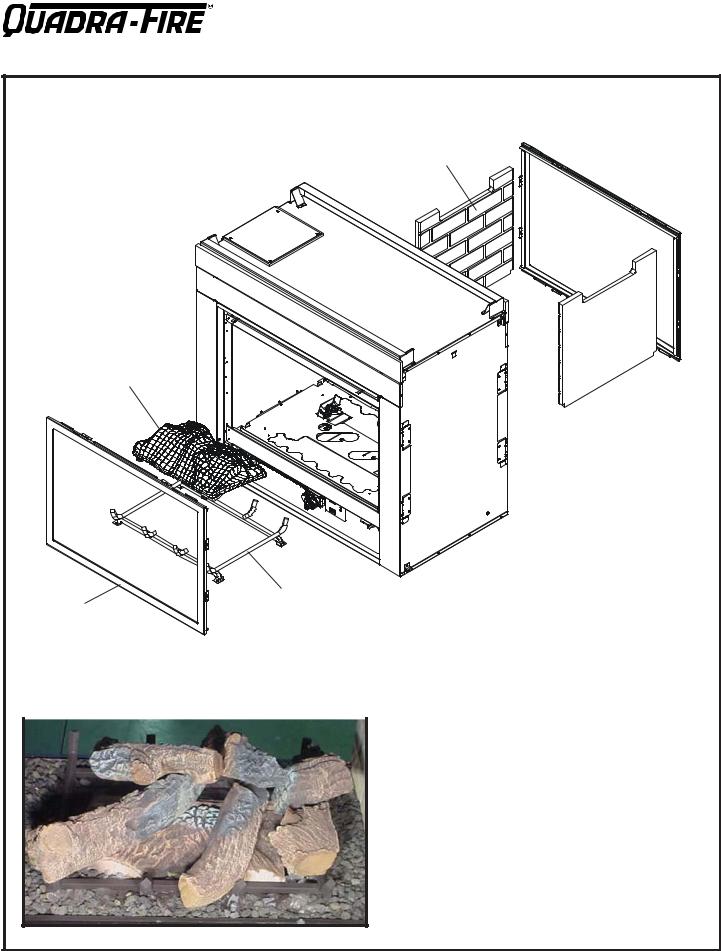
Service Parts List |
QV-Pier-HV-IPI |
|
|
(NG, LP) Exploded Parts Diagram |
Beginning Manufacturing Date: 6-03 |
|
Ending Manufacturing Date: ______ |
3
1
|
4 |
5 |
|
|
|
2 |
|
6 Log Assembly |
|
|
12 711 139
7 |
10 |
8 |
Part number list on following page.
4 |
Quadra-Fire • QV-PIER, QV-ST Series: HV-IPI • 2005-901 Rev. G • 2/06 |
SERVICE PARTS LIST |
QV-PIER-HV-IPI |
IMPORTANT: THIS IS DATED INFORMATION. The most current information is located on your dealers VIP site. When ordering, supply serial and model numbers to ensure correct service parts.
ITEM |
|
COMMON PART |
SERIAL # |
PART NUMBER |
|
|
Burner Orifice NG (#33DMS) |
|
582-833 |
|
|
|
|
|
|
|
Burner Orifice LP (#50DMS) |
|
582-850 |
|
|
|
|
|
1 |
|
End Glass Assembly |
|
GLA-MS |
|
|
|
|
|
2 |
|
Glass Door Assembly |
|
GLA-6TROC |
|
|
|
|
|
3 |
|
Burner Assembly |
|
2005-006 |
|
|
|
|
|
4 |
|
Log Grate |
|
2005-012 |
|
|
|
|
|
5 |
|
Side Refractory |
|
SRV2005-730 |
|
|
|
|
|
6 |
|
Log Set Assembly |
|
LOGS-MSR |
|
|
|
|
|
7 |
|
Log 1 |
|
SRV2005-701 |
|
|
|
|
|
8 |
|
Log 2 |
|
SRV2005-700 |
|
|
|
|
|
9 |
|
Log 3 |
|
SRV2005-702 |
|
|
|
|
|
10 |
|
Log 4 |
|
SRV2005-703 |
|
|
|
|
|
11 |
|
Log 5 |
|
SRV2005-704 |
|
|
|
|
|
12 |
|
Log 6 |
|
SRV2005-705 |
|
|
|
|
|
13 |
|
Log 7 |
|
SRV703-703 |
|
|
|
|
|
|
|
Andirons |
|
80784 |
|
|
|
|
|
|
|
Lava Rock Bag |
|
2005-790 |
|
|
|
|
|
|
|
Flue Restrictor |
|
385-128 |
|
|
Teco-Sil, 5 lb. bag |
|
700-790 |
|
|
Mineral Wool |
|
050-721 |
|
|
Fiberglass Rope |
|
060-455 |
|
|
|
|
|
|
|
Bracket, Andiron |
|
2005-149 |
|
|
|
|
|
|
|
Kapton, Lens |
|
2005-165 |
|
|
Glass Latch Support Assembly |
|
386-122A |
|
|
Insullation Board (side) |
|
2006-136 |
|
|
|
|
|
|
|
Insullation Board (end) |
|
2006-137 |
|
|
|
|
|
|
|
Ember Mesh Assembly |
|
2006-008 |
|
|
|
|
|
|
|
Junction Box |
|
4021-013 |
|
|
3V Plug |
|
593-593A |
|
|
Conversion Kit NG |
|
NGK-MS |
|
|
Conversion Kit LP |
|
LPK-MS |
|
|
Pilot Tube |
|
SRV485-301 |
|
|
Battery Pack |
|
593-594A |
|
ACCESSORIES |
|
|
|
|
|
Fan Kit |
|
GFK-160A |
|
|
Remote Control Kit |
|
RC-SMART-HNG |
|
|
Remote Control Kit |
|
SMART-STAT-HNG |
|
|
Remote Control - Multi-functional |
|
RCT-MLT-HNG |
|
|
Wall Switch, Multi-functional |
|
WSK-MLT |
|
|
Plug Adapator Kit (for WSK-MLT |
|
PLUG-ADP |
Í
Í
Í
Í
Í
Í
Í
Quadra-Fire • QV-PIER, QV-ST Series: HV-IPI • 2005-901 Rev. G • 2/06 |
5 |
Service Parts |
QV-ST-HV-IPI |
|
|
(NG, LP) Exploded Parts Diagram |
Beginning Manufacturing Date: 6-03 |
|
Ending Manufacturing Date: ______ |
4
2
1 |
3 |
5 Log Assembly |
|
|
|
|
|
11 |
710 |
12 |
|
|
8 |
6 |
9 |
7 |
|
|
Part number list on following page.
6 |
Quadra-Fire • QV-PIER, QV-ST Series: HV-IPI • 2005-901 Rev. G • 2/06 |
SERVICE PARTS LIST |
QV-ST-HV-IPI |
IMPORTANT: THIS IS DATED INFORMATION. The most current information is located on your dealers VIP site. When ordering, supply serial and model numbers to ensure correct service parts.
ITEM |
|
COMMON PART |
SERIAL # |
PART NUMBER |
|
|
|
|
|
|
|
Burner Orifice NG (#32DMS) |
|
582-832 |
|
|
|
|
|
|
|
Burner Orifice LP (#50DMS) |
|
582-850 |
|
|
|
|
|
1 |
|
Glass Door Assembly |
|
GLA-6TROC |
|
|
|
|
|
2 |
|
Burner Assembly |
|
2005-006 |
|
|
|
|
|
3 |
|
Log Grate |
|
2005-012 |
|
|
|
|
|
4 |
|
Side Refractory |
|
SRV2005-730 |
|
|
|
|
|
5 |
|
Log Set Assembly |
|
LOGS-MSR |
|
|
|
|
|
6 |
|
Log 1 |
|
SRV2005-701 |
|
|
|
|
|
7 |
|
Log 2 |
|
SRV2005-700 |
|
|
|
|
|
8 |
|
Log 3 |
|
SRV2005-702 |
|
|
|
|
|
9 |
|
Log 4 |
|
SRV2005-703 |
|
|
|
|
|
10 |
|
Log 5 |
|
SRV2005-704 |
|
|
|
|
|
11 |
|
Log 6 |
|
SRV2005-705 |
|
|
|
|
|
12 |
|
Log 7 |
|
SRV703-703 |
|
|
|
|
|
|
|
Andirons |
|
80784 |
|
|
|
|
|
|
|
Lava Rock Bag |
|
2005-790 |
|
|
|
|
|
|
|
Flue Restrictor |
|
385-128 |
|
|
|
|
|
|
|
Teco-Sil, 5 lb. bag |
|
700-790 |
|
|
|
|
|
|
|
Hood, Black |
|
SRV60-143-BK |
|
|
|
|
|
|
|
Glass Latch Support Assembly |
|
386-122A |
|
|
|
|
|
|
|
Mineral Wool |
|
050-721 |
|
|
|
|
|
|
|
Fiberglass Rope |
|
060-455 |
|
|
Bracket, Andiron |
|
2005-149 |
|
|
|
|
|
|
|
Kapton, Lens |
|
2005-165 |
|
|
|
|
|
|
|
Non-Combustible board |
|
2005-172 |
|
|
Ember Mesh Assembly |
|
2005-008 |
|
|
Junction Box |
|
4021-013 |
|
|
3V Plug |
|
593-593A |
|
|
Conversion Kit NG |
|
NGK-MS |
|
|
Conversion Kit LP |
|
LPK-MS |
|
|
Pilot Tube |
|
SRV485-301 |
|
|
Battery Pack |
|
593-594A |
|
ACCESSORIES |
|
|
|
|
|
Fan Kit |
|
GFK-160A |
|
|
Remote Control Kit |
|
RC-SMART-HNG |
|
|
Remote Control Kit |
|
SMART-STAT-HNG |
|
|
Remote Control - Multi-functional |
|
RCT-MLT-HNG |
|
|
Wall Switch, Multi-functional |
|
WSK-MLT |
|
|
Plug Adapator Kit (for WSK-ML |
|
PLUG-ADP |
|
|
|
|
|
Í
Í
Í
Í
Í
Í
Í
Í
Quadra-Fire • QV-PIER, QV-ST Series: HV-IPI • 2005-901 Rev. G • 2/06 |
7 |
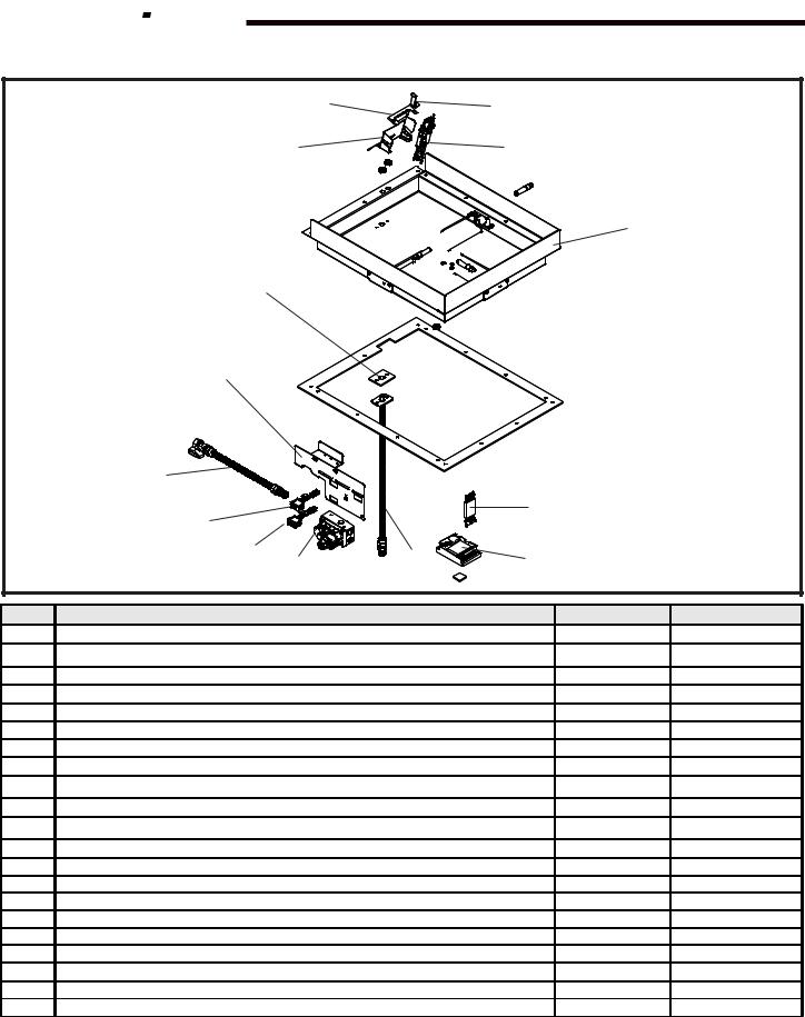


 Service Parts
QV-PIER-HV-IPI QV-ST-HV-IPI
|
(NG, LP) Exploded Parts Diagram |
Beginning Manufacturing Date: 6-03 |
|
|
Ending Manufacturing Date: ______ |
Î |
13 |
14 |
|
||
|
9 |
8 |
7
10
11
|
12 |
|
|
6 |
|
|
|
1 |
|
|
|
|
|
|
|
|
|
|
|
|
|
2 |
3 |
4 |
5 |
|
|
Î ITEM |
|
DESCRIPTION |
|
SERIAL # |
PART NUMBER |
|
1 |
ON/OFF Rocker Switch |
|
|
|
060-511 |
|
2 |
ON/OFF Wire Assembly |
|
|
|
060-521A |
|
3 |
Valve NG |
|
|
|
750-500 |
|
3 |
Valve LP |
|
|
|
750-501 |
|
4 |
Flexible Gas Connector |
|
|
|
2005-009 |
|
5 |
Module |
|
|
|
593-592 |
|
6 |
Wire Assembly |
|
|
|
593-590A |
|
7 |
Ember Box Assembly |
|
|
|
2005-114 |
|
8 |
Pilot Assembly NG |
|
|
|
385-510A |
|
8 |
Pilot Assembly LP |
|
|
|
385-511A |
|
9 |
Pilot Bracket |
|
|
|
2005-118 |
|
10 |
Gasket Orifice |
|
|
|
2005-166 |
|
11 |
Valve Bracket |
|
|
|
2005-120 |
|
12 |
Flex Ball Valve Assembly |
|
|
|
302-320A |
|
13 |
Pilot Assembly Support |
|
|
|
385-120 |
|
14 |
Ground Strap |
|
|
|
385-512 |
Í |
|
Regulator, NG |
|
|
|
NGK-DXV |
|
|
Regulator, LP |
|
|
|
LPK-DXV |
Í |
|
Pilot Tube |
|
|
|
446-301 |
|
|
Orifice Spud NG |
|
|
|
446-505 |
|
|
Orifice Spud LP |
|
|
|
446-517 |
|
NOTE: Replacement bulbs to be supplied by homeowner. Recommended replacements: Sylvania Mini Candelabra 75 watts.
8 |
Quadra-Fire • QV-PIER, QV-ST Series: HV-IPI • 2005-901 Rev. G • 2/06 |

1Approvals and Codes
Appliance Certification
The Quadra-Fire fireplace models discussed in this Installers Guide have been tested to certification standards and listed by the applicable laboratories.
Certification
MODELS: QV-PIER-HV-IPI, QV-ST-HV-IPI
LABORATORY: Underwriters Laboratories
TYPE: Vented Gas Fireplace Heater
STANDARD: ANSI Z21.88•CGA2.22•UL307B
Installation Codes
High Altitude Installations
U.L. Listed gas appliances are tested and approved without requiring changes for elevations from 0 to 2,000 feet in the U. S. A. and in Canada.
When installing this appliance at an elevation above 2,000 feet, it may be necessary to decrease the input rating by changing the existing burner orifice to a smaller size. Input rate should be reduced by 4% for each 1000 feet above a 2000 foot elevation in the U.S.A. or 10% for elevations between 2000 and 4500 feet in Canada. If the heating value of the gas has been reduced, these rules do not apply. To identify the proper orifice size, check with the local gas utility.
The fireplace installation must conform to local codes. Before installing the fireplace, consult the local building code agency to ensure that you are in compliance with all applicable codes, including permits and inspections.
In the absence of local codes, the fireplace installation must conform to the National Fuel Gas Code ANSI Z223.1 (in the United States) or the CAN/CGA-B149 Installation Codes (in Canada). The appliance must be electrically grounded in accordance with local codes or, in the absence of local codes with the National Electric Code ANSI/NFPA No. 70 (in the United States), or to the CSAC22.1 Canadian Electric Code (in Canada).
These models may be installed in a bedroom or bed-sitting room in the U.S.A. and Canada.
If installing this appliance at an elevation above 4,500 feet (in Canada), check with local authorities.
Quadra-Fire • QV-PIER, QV-ST Series: HV-IPI • 2005-901 Rev. G • 2/06 |
9 |

2Getting Started
Introducing the Quadra-Fire Gas Fireplaces
Quadra-Fire direct vent gas fireplaces are designed to operate with all combustion air siphoned from outside of the building and all exhaust gases expelled to the outside.
The information contained in this Installers Guide, unless noted otherwise, applies to all models and gas control systems. Gas fireplace diagrams, including the dimensions, are shown in this section.
Pre-install Preparation
This gas fireplace and its components are tested and safe when installed in accordance with this Installers Guide. Report to your dealer any parts damaged in shipment, particularly the condition of the glass. Do not install any unit with damaged, incomplete, or substitute parts.
The vent system components are shipped in separate packages. The gas logs are packaged separately and must be field installed.
Read all of the instructions before starting the installation. Follow these instructions carefully during the installation to ensure maximum safety and benefit. Failure to follow these instructions will void the owner’s warranty and may present a fire hazard.
The Quadra-Fire Warranty will be voided by, and QuadraFire disclaims any responsibility for, the following actions:
•Installation of any damaged fireplace or vent system component.
•Modification of the fireplace or direct vent system.
•Installation other than as instructed by Quadra-Fire.
•Improper positioning of the gas logs or the glass door.
•Installation and/or use of any component part not manufactured and approved by Quadra-Fire, not withstanding any independent testing laboratory or other party approval of such component part or accessory.
ANY SUCH ACTION MAY POSSIBLY CAUSE A FIRE HAZARD.
When planning a fireplace installation, it’s necessary to determine:
•Where the unit is to be installed.
•The vent system configuration to be used.
•Gas supply piping.
•Electrical wiring.
•Framing and finishing details.
•Whether optional accessories—devices such as a fan, wall switch, or remote control—are desired.
If the fireplace is to be installed on carpeting or tile, or on any combustible material other than wood flooring, the fireplace should be installed on a metal or wood panel that extends the full width and depth of the fireplace.
10 |
Quadra-Fire • QV-PIER, QV-ST Series: HV-IPI • 2005-901 Rev. G • 2/06 |
|
|
5-1/4 |
|
|
|
|
|
|
(133mm) |
|
|
|
|
|
|
|
1/2 |
|
|
|
|
|
|
(13mm) |
|
|
|
|
|
|
12 |
|
|
|
|
|
(306mm) |
|
|
|
|
|
|
|
Ø8 |
|
|
|
|
|
|
(205mm) |
|
|
|
|
12 |
Ø8 |
|
42-5/8 |
|
|
|
(305mm) |
|
(1082mm) |
|
|
|
|
|
(205mm) |
|
|
|
|
|
|
ELECTRICAL |
|
|
|
|
|
|
ACCESS |
|
|
|
|
|
|
|
42 |
32-5/16 |
|
|
|
|
|
(820mm) |
|
21-9/16 |
|
34-3/4 |
|
GAS LINE |
(1067mm) |
|
21-9/16 |
(547mm) |
|
ACCESS |
|
|
|
||
(883mm) |
|
|
|
(547mm) |
|
|
|
|
|
|
|
||
4-1/16 |
|
2-5/16 |
|
|
17-15/16 |
|
|
(58mm) |
|
|
|
||
(102mm) |
|
|
37-7/16 |
(455mm) |
|
|
|
|
|
|
|||
|
|
|
|
|
|
|
|
|
|
|
(950mm) |
24 |
|
4-1/2 |
|
4-3/4 |
|
|
|
|
|
|
|
(610mm) |
|
||
(114mm) |
|
(121mm) |
|
|
|
|
|
|
|
|
|
||
TOP VENT |
|
|
|
|
|
|
COLLARS |
|
TOP STANDOFFS |
|
|
|
|
|
|
|
|
|
|
|
|
|
|
|
|
REAR VENT |
|
|
|
|
|
|
COLLARS |
|
|
|
|
|
SIDE GLASS |
|
|
|
GAS CONTROLS |
|
|
DOOR |
|
|
|
& LABELS |
|
|
|
GAS LINE |
|
|
|
|
|
|
|
|
|
|
|
|
|
ACCESS |
|
|
|
|
|
|
ELECTRICAL |
|
|
|
|
|
|
ACCESS |
|
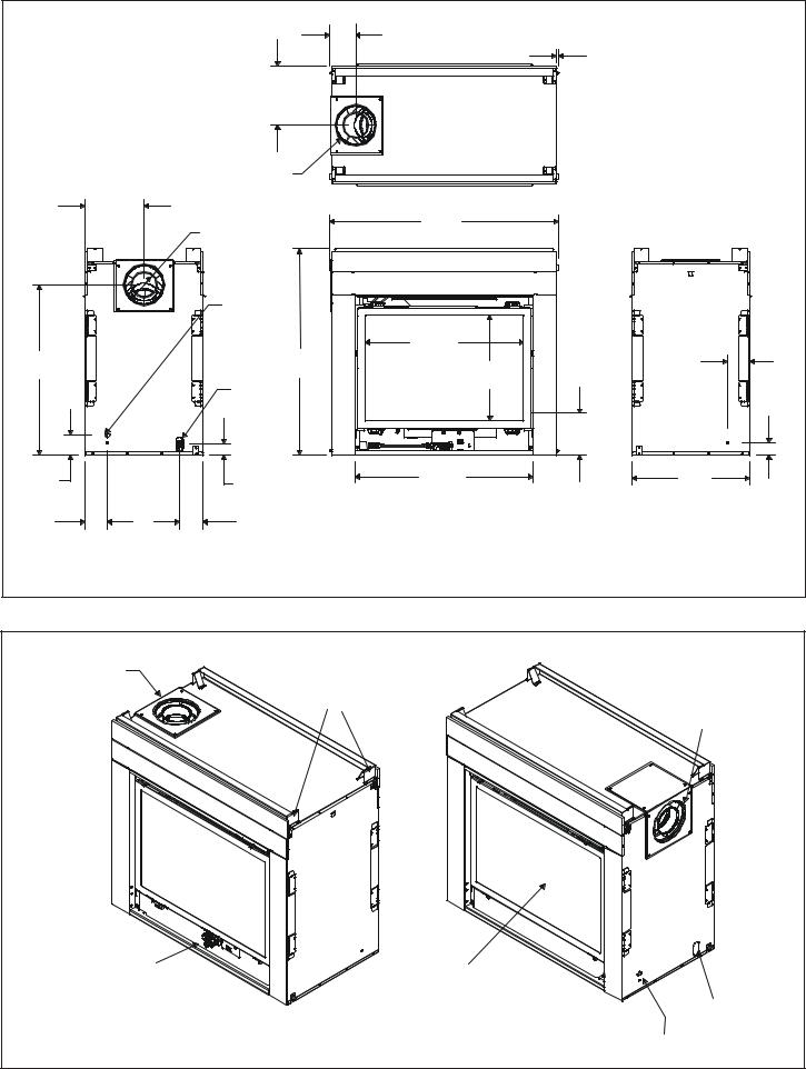
Figure 1. |
Diagram of the QV-PIER-HV-IPI |
|
|
|
||
|
|
Quadra-Fire • QV-PIER, QV-ST Series: HV-IPI • 2005-901 Rev. G • 2/06 |
11 |
|||
|
|
|
5-14 |
|
|
|
|
|
(133mm) |
1/2 |
|
|
|
|
|
|
|
|
|
|
|
(13mm) |
|
|
|
|
|
(4) |
|
|
|
12 |
|
|
|
|
|
(306mm) |
|
|
|
|
|
Ø8 |
|
|
|
|
|
(205mm) |
|
|
|
|
|
12 |
|
|
|
|
|
(305mm) |
|
|
|
|
|
Ø8 |
46-5/8 |
|
|
|
|
(205mm) |
(1183mm) |
|
|
|
|
ELECTRICAL |
|
|
|
|
|
ACCESS |
|
|
|
|
|
|
32-5/16 |
|
|
34-3/4 |
|
42 |
(821mm) |
4-1/2 |
|
|
|
(114mm) |
|
||
(882mm) |
|
(1067mm) |
|
21-9/16 |
|
|
|
GAS LINE |
|
(548mm) |
|
|
|
ACCESS |
|
|
|
|
|
|
|
|
|
|
|
|
|
8-1/2 |
|
|
|
|
|
(216mm) |
|
4-1/16 |
|
2-5/16 |
36-3/16 |
24 |
|
|
(58mm) |
(919mm) |
(610mm) |
2-9/16 |
|
(102mm) |
|
|
|
|
(64mm) |
4-1/2 |
|
4-3/4 |
|
|
|
(114mm) |
|
(121mm) |
|
|
|
Figure 2. |
Dimensions of the QV-ST-HV-IPI |
|
|
|
|
|
TOP VENT |
|
|
|
|
|
COLLARS |
|
|
|
|
|
|
TOP STANDOFFS |
|
REAR VENT |
|
|
|
|
|
|
|
|
|
|
|
COLLARS |
|
GAS CONTROLS |
SIDE GLASS |
& LABELS |
DOOR |
GAS LINE
ACCESS
Figure 3. Diagram of the QV-ST-HV-IPI
ELECTRICAL
ACCESS
12 |
Quadra-Fire • QV-PIER, QV-ST Series: HV-IPI • 2005-901 Rev. G • 2/06 |
3Installing the Fireplace
Step 1. Locating the Fireplace
The diagram below shows space and clearance requirements for locating a fireplace within a room.
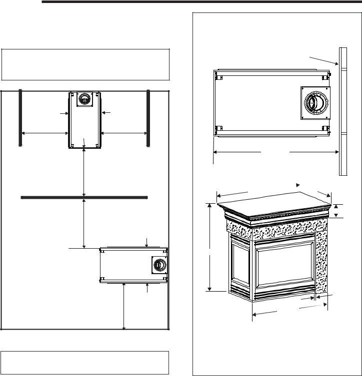
ÎNote: Refer to Figure 4B for dimensions and appliance locations if installing a QV-PIER-HV unit with a Catalina shelf and/or marble package.
GLASS |
QV-PIER-HV-IPI |
GLASS |
|
|
|
|
TOP VIEW |
|
36" |
GLASS |
36" |
36"
36"
GLASS
QV-ST-HV-IPI
TOP VIEW
GLASS
36"
Figure 4A. Fireplace Dimensions and Locations
ÎNote: Refer to the Catalina installation instruction included with kit for assembly and installation.
Note: This location diagram MUST be followed when installing a QV-Pier-HV with a Catalina shelf/marble package since the fireplace is installed further from finished wall.
FINISHED
WALL
45 -1/4 in. (1149mm)
50-1/2 in.

 34-1/2 in.

 7 in.
7 in.
47-1/2 in.
|
|
13/16 in. |
|
|
|
45-1/4 in. |
|
Marble sizes (inches): |
|
||
Header .................................. |
26 x 8 |
|
|
Side headers .................. |
45-1/2 x 8 |
|
|
Legs |
................................ |
33-1/2 x 7 |
|
Figure 4B. |
Fireplace Locations/Dimensions with |
Í |
|
|
Catalina Shelf/Marble Package ONLY |
||
|
|
||
Clearance Requirements
The top, back, and sides of the fireplace are defined by stand-offs. The minimum clearance to a perpendicular wall extending past the face of the fireplace is one inch (25 mm). The metal ends of the fireplace may NOT be recessed into combustible construction.
Quadra-Fire • QV-PIER, QV-ST Series: HV-IPI • 2005-901 Rev. G • 2/06 |
13 |
 Loading...