

Page 1
Owner’s Manual
Installation and service of this appliance should be performed by
qualified personnel. Hearth & Home Technologies recommends
HHT Factory Trained or NFI certified professionals.
R
Operation & Care
INSTALLER: Leave this manual with party responsible for use and operation.
OWNER: Retain this manual for future reference.
Contact your dealer with questions on installation, operation, or service.
NOTICE: DO NOT DISCARD THIS MANUAL
PELLET BURNING STOVE
MODEL NUMBER:
CAB50-C
WARNING
If the information in these instructions is
not followed exactly, a re could result
causing property damage, personal injury,
or death.
• Do not store or use gasoline or other ammable
vapors and liquids in the vicinity of this or any
other appliance.
• Do not over re - If appliance or chimney connector
glows, you are over ring. Over ring will void
your warranty.
• Comply with all minimum clearances to combustibles
as specied.
Failure to comply may cause house re.
WARNING
HOT SURFACES!
Glass and other surfaces are hot during
operation AND cool down.
Hot glass will cause burns.
• Do not touch glass until it is cooled
• NEVER allow children to touch glass
• Keep children away
• CAREFULLY SUPERVISE children in same room
as replace.
• Alert children and adults to hazards of high
temperatures
• High temperatures may ignite clothing or other
ammable materials.
• Keep clothing, furniture, draperies and other
ammable materials away.
CAUTION
Tested and approved for wood pellets, Burning of any
other type of fuel voids your warranty.
1 04/217074-804F
CAUTION
Check building codes prior to installation.
• Installation MUST comply with local, regional, state
and national codes and regulations.
• Consult local building, re ocials or authorities
having jurisdiction about restrictions, installation
inspection, and permits.
NOTE: To obtain a French translation of this
manual, please contact your dealer or visit
www.quadrare.com.
REMARQUE : Pour obtenir une traduction française de
ce manuel, s’il vous plaît contacter votre
revendeur ou visitez www.quadrare.com.
Page 2

BARCODE LABEL
MINIMUM CLEARANCES TO COMBUSTIBLE MATERIALS /
ESPACES LIBRES MINIMUM DES MATÉRIAUX COMBUSTIBLES:
DO NOT REMOVE THIS LABEL / NE PAS ENLEVER L'ÉTIQUETTE
7074-805A
Made in U.S.A. of US and imported parts. / Fabriqué aux États-Unis-d’Amérique par des pièces d’origine américaine et pièces importées.
A
B
C
C
D
E
F
C
C
USA
G = 2 in
H* = 2 in
I = 6 in
CANADA
G = 203 mm
H* = 51 mm
I = 152 mm
G
H
I
G
U.S. ENVIRONMENTAL PROTECTION AGENCY
Certified to comply with 2020 particulate emission standards at 1.0 g/hr EPA method 28R and ASTM 2779 using premium wood pellets.
This wood heater needs periodic inspection and repair for proper operation. Consult the owner’s manual for further information. It is against federal regulations to operate this wood
heater in a manner inconsistent with the operating instructions in the owner’s manual.
2020
2021
2022 JAN FEB MAR APR MAY JUN
JUL AUG SEP OCT NOV DEC
C# 4001508
Manufactured by: Fabriqué par:
352 Mountain House Road
Halifax, Pa 17032
www.quadrafire.com
CAB50-C
Serial No.
N° de série
HF
0061PS085E
CAUTION
:
HOT WHILE IN OPERATION DO NOT TOUCH, KEEP CHILDREN AND
CLOTHING AWAY. CONTACT MAY CAUSE SKIN BURNS.
CHAUD LORS DE L'OPÉRATION. NE PAS TOUCHER. GARDEZ LES ENFANTS ET LES VÊTEMENTS
LOIN DE L'ESPACE DÉSIGNÉ DE L'INSTALLATION. LE CONTACT PEUT CAUSER
DES BRÛLURES À LA PEAU. GARDEZ LES MEUBLES ET LES MATÉRIAUX COMBUSTIBLES LOIN DE
L'ESPACE DÉSIGNÉ DE L'APPAREIL. VOIR L'ÉTIQUETTE ET LES INSTRUCTIONS.
ATTENTION:
KEEP FURNISHINGS AND OTHER COMBUSTIBLE MATERIAL FAR AWAY FROM
THE APPLIANCE. SEE NAMEPLATE AND INSTRUCTIONS
*
Non-combustible floor protection must extend 2 inches (51mm) beneath
the flue pipe when installed with horizontal venting or under the Top Vent
Adapter with vertical installation. RECOMMENDED IN USA; REQUIRED
IN CANADA.
*Un protecteur incombustible de plancher doit s'étendre 2 inches (51mm) sous le
conduit de cheminée pour une installation de ventilation horizontale ou sous un
adapteur de ventilation de dessus pour une installation verticale.
ÉTATS-UNIS -
RECOMMANDÉ; CANADA - REQUIRENT.
Floor protector must be non-combustible material, extending beneath
heater and to the front/sides/rear as indicated. Measure front distance (I)
from the surface of the glass door.
Le poêle doit être placé sur une assise non combustible s’étendant tout autour de lui,
comme les schémas l’indiquent. Mesurez la distance du devant (I) de la surface de
la porte vitrée.
FLOOR PROTECTION / PROTECTION DU SOL
NOTE 1:
In residential installations, when using Parts TPVNT-5, (3" - 3" Top Vent Adapter) and
812-3570 (3" - 6" Offset Adapter) or 811-0720 (3” - 4” Offset Adapter), 24 gauge 6" single wall flue
connector may be used. /
REMARQUE 1 : Dans les installations résidentielles, lorsque les pièces
TPVNT-5, (dessus de l'adapteur de ventilation 3 po - 3 po) et 812-3570 (le ressaut de l'adapteur 3
po - 6 po) ou 811-0720 (le ressaut de l'adapteur 3 po - 4 po), un tuyau connecteur de 6 po pour mur
simple de calibre 24 peut être utilisé.
NOTE 2: In manufactured home installation, when using Part TPVNT-5, (3" - 3" Top Vent Adapter)
and 812-3570 (3" - 6" Offset Adapter)
or 811-0720 (3” - 4” Offset Adapter)
, use listed double wall
flue connector. An Outside Air Kit (Part 811-0872), must be used with manufactured home
installation. / REMARQUE 2 : Pour l'installation dans les maisons préfabriquées, lorsque les pièces
TPVNT-5, (dessus de l'adapteur de ventilation 3 po - 3 po) et 812-3570 (le ressaut de l'adapteur 3
po - 6 po) ou 811-0720 (le ressaut de l'adapteur 3 po - 4 po), utilisez un tuyau connecteur
enregistré pour mur double. Un assemblage d'air extérieur (Part 811-0872), doit être utilisé pour
l'installation dans les maisons préfabriquées.
A Back Wall / Mur Arrière 2 in [51mm]
B Side Wall / Mur De Côté 14 in [356mm]
CORNER INSTALLATION / NSTALLATION DU COIN :
C Side Wall / Mur De Côté 2 in [51mm]
VERTICAL 3 in. - 3 in. ADAPTER KIT (PART TPVNT-5) INSTALLATION:
UN ASSEMBLAGE POUR ADAPTEUR 3- 3 in (76-76mm) (PIÈCE TPVNT-5) POUR INSTALLATION VERTICALE:
D Pipe to Back Wall / Un Tuyau Mur Arrière 1 in [25mm]
E Side Wall / Mur De Côté 14 in [356mm]
F Back Wall / Mur Arrière 6.25 in [159mm]
CORNER INSTALLATION WITH VERTICAL ADAPTER KIT:
INSTALLATION DU COIN AVEC UN ASSEMBLAGE D'ADAPTEUR VERTICAL
:
G Side Wall / Mur De Côté 2 in [51mm]
ALCOVE INSTALLATION /
INSTALLATION DE L' ALCÔVE
:
Min. Alcove Height: /
Une hauteur minimum de l'alcôve
56.75 in [
1441mm]
Min. Alcove Side Wall: /
Une hauteur minimum m
ur de côté
de l'alcôve
14 in [356mm]
Min. Alcove Width /
Une épaisseur minimum m
ur de côté
de l'alcôve
53 in [1346mm]
Max. Alcove Depth: /
La profondeur maximum de l'alcôve
48 in [1219mm]
Max. Mantle Depth: /
Profondeur maximum de la manteau de cheminée 36 in [914mm]
Top of Unit to Combustibles: / Vue du haut des matériaux combustibles 21 in [533mm]
Listed Solid Fuel Room Heater/Pellet Type.
Also suitable for Mobile Home Installation. This appliance
has been tested and listed for use in Manufactured Homes in accordance with OAR 814-23-9000
through 814-23-909.
Certified to: ASTM STD E1509, Certified to: ULC STD S627 Room Heating Pellet BurningType, (UM)
84-HUD FOR USE
ONLY WITH PELLETIZED WOOD.
Do not use any other type of fuel. Intertek-Test
Laboratories has determined that this appliance complies with Canadian Standards Association (CSA)
B415.1 and Title 40 of the U.S. Code of Federal Regulations, Part 60, SubPart AAA.
Input Rating: 49,869 Btu's/hr. Electrical Rating: 115 VAC, 60 Hz, Start 5.1 Amps, Run 3.0 AMPS.
Route power cord away from unit. Do not route cord under or in front of appliance. Do not obstruct the
space beneath the heater.
DANGER:
Risk of electrical shock. Disconnect power supply before servicing. Replace glass only with
5mm ceramic available from your dealer. To start, set thermostat above room temperature, the stove will
light automatically. To shutdown, set thermostat to below room temperature. For further instruction refer to
owner's manual.
Keep viewing and ash removal doors tightly closed during operation.
PRÉVENTION DES FEUX DE MAISON
I
nstallez et utilisez en accord avec les instructions d'installation et d'opération du fabricant. Contactez le bureau de la
construction ou le bureau des incendies au sujet des restrictions et des inspections d'installation dans votre voisinage. Ne pas
obstruez l'espace en dessous de l'appareil.
A
VIS - Pour Les Maisons Mobiles : Ne pas installer dans une chambre à coucher. Un tuyau extérieur de combustion d'air
doit être installé et ne doit pas être obstrué lorsque l'appareil est en usage. La structure intégrale du plancher, du plafond et des
murs de la maison mobile doit être
maintenue intacte.
Référez vous aux instructions du fabricant et des codes locaux pour les précautions requises pour passer une cheminée à
travers un mur ou un plafond combustibles, et les compensations maximums.
Inspectez et nettoyez la cheminée fréquemment. Ne pas connecter cet appareil à une cheminée servant un autre appareil.
Utilisez systèm de ventilation "L" ou "P" diamètre 76mm ou 102mm
Certifié à : ASTM E1509, Certifié à : ULC S627 Room Heating. Pellet Burning Type, (UM) 84-HUD POUR USAGE AVEC
LES BOULETTES DE BOIS. N’utiliser aucun autre genre de combustible.
Intertek Test Laboratories a déterminé que cet
appareil se conforme avec la norme de l’Association Canadienne de normalisation (CSA) B415.1 ainsi que le Titre 40
du Code Fédéral de Régulations des États-Unis, partie 60, sous-partie AAA.
Puissance de Rendement : 49,869 Btu's/hr. Puissance Électrique : 115 VAC, 60 Hz, Début 5.1 Amps, Courir 3.0 Amps,
Éloignez le fil électrique de l'appareil. Ne pas faire passer le fil électrique au dessus ou en dessous de l'appareil. Ne pas bloquer
l’espace au dessous de l’appareil.
DANGER : Il y a risque de décharge électrique. Déconnectez le fil électrique de la prise de contact avant le service.
Remplacez la vitre seulement avec une vitre céramique de 5 mm disponible chez votre fournisseur.
Pour allumer, monter la température du thermostat au dessus de la température de la pièce, le poêle s'allumera automatiquement.
Pour éteindre, descendre la température du thermostat en dessous de la température de la pièce. Pour des instructions
supplémentaires, référez vous au manuel du propriétaire. Gardez la porte d'ouverture et la porte des cendres fermées
hermétiquement durant l'opération.
Appareil de chauffage de combustible solide/de type de boulettes.
Accepté dans l'installation dans les maisons mobiles. Cet appareil a été testé et enregistré pour l'usage dans les
Maisons Mobiles en accord avec OAR 814-23-9000 jusqu'à 814-23-909.
PREVENT HOUSE FIRES
Install and use only in accordance with manufacturer's installation and operating instructions. Contact local
building or fire officials about restrictions and inspection in our area.
WARNING - FOR MOBILE HOMES: Do not install appliance in a sleeping room. An outside combustion
air inlet must be provided. The structural integrity of the mobile home floor, ceiling and walls must be
maintained.
Refer to manufacturer's instructions and local codes for precautions required for passing chimney
through a combustible wall or ceiling. Inspect and clean vent system frequently in accordance with
manufacturer's instructions.
DO NOT CONNECT THIS UNIT TO A CHIMNEY SERVING ANOTHER APPLIANCE.
Use a 3" or 4" diameter type "L" or "PL" venting system.
Refer to the Intertek Directory of Building Products (https://bpdirectory.intertek.com) for detailed information.
Reportez-vous au répertoire des produits de construction d'Intertek (https://bpdirectory.intertek.com) pour obtenir des informations détaillées.
R
NOTE: Clearances may only be reduced by means approved by the regulatory
authority having jurisdiction
A. Sample of Serial Number / Safety Label
LOCATION: Back of appliance
Test Lab
and Report
Number
2 04/217074-804F
and Welcome to the Quadra-Fire Family!
Model Name
SAMPLE
Serial Number
Manufacturer
Date
Page 3

Safety Alert Key:
• DANGER! Indicates a hazardous situation which, if not avoided will result in death or serious injury.
• WARNING! Indicates a hazardous situation which, if not avoided could result in death or serious injury.
• CAUTION! Indicates a hazardous situation which, if not avoided, could result in minor or moderate injury.
• NOTICE: Indicates practices which may cause damage to the appliance or to property.
TABLE OF CONTENTS
A. Sample of Serial Number / Safety Label ........... 2
B. Warranty Policy ..............................4
C. Quick Start Guide............................. 6
1 Listing and Code Approvals
A. Appliance Safety Certication ...................7
B. Appliance Emissions Certication ................7
C. BTU & Eciency Specications.................. 7
D. Glass Specications........................... 8
E. Electrical Rating (on high) ...................... 8
F. Mobile Home Approved ........................8
G. Sleeping Room .............................. 8
H. California - Prop65............................ 8
2 Operating Instructions
A. Fire Safety .................................. 9
B. Non-Combustible Materials ..................... 9
C. Combustible Materials .........................9
D. Fuel Material and Fuel Storage . . . . . . . . . . . . . . . . . . 9
E. General Operating Information.................. 10
F. Before Your First Fire ......................... 10
G. Hopper Lid and Hopper Switch ................. 11
H. Starting Your First Fire ........................ 11
I. Fire Characteristics . . . . . . . . . . . . . . . . . . . . . . . . . . . 12
J. Feed Rate Adjustment Instructions............... 12
K. Ignition Cycles .............................. 12
L. Clear Space ................................ 13
M. Thermostat Operation ........................ 13
N. Frequently Asked Questions ...................14
3 Maintenance and Service
A. Proper Shutdown Procedure ................... 15
B. Quick Reference Maintenance Chart............. 15
C. General Maintenance......................... 16
D. High Ash Fuel Content Maintenance ............. 20
E. Soot or Creosote Fire......................... 20
4 Troubleshooting Guide....................... 21
5 Service Parts Replacement
A. Side Curtain Replacement ..................... 24
B. Convection Blower Replacement................ 24
C. Exhaust Blower Replacement .................. 25
D. Snap Disc #1, #2, #3 Replacement ..............25
E. Igniter Replacement.......................... 26
F. Bae Replacement .......................... 26
G. Glass Replacement ..........................27
6 Reference Materials
A. Component Functions ........................ 28
B. Component Locations ........................ 30
C. Maintenance and Service Log ..................31
D. Service Parts List............................ 35
= Contains updated information
Quadra-Fire is a registered trademark of Hearth & Home Technologies.
3 04/217074-804F
Page 4

B. Warranty Policy
Igniters, Auger Motors, Electronic Components, and
See condi�ons, exclusions and limita�ons on the next page
Hearth & Home Technologies
LIMITED LIFETIME WARRANTY
Hearth & Home Technologies, on behalf of its hearth brands (“HHT”), extends the following warranty for HHT gas, wood, pellet and
electric hearth appliances that are purchased from an HHT authorized dealer.
WARRANTY COVERAGE:
WARRANTY PERIOD:
distributor, whichever occurs earlier. However, the warranty shall commence no later than 24 months following the date of product
is produced in the following table.
Warranty Period HHT Manufactured Appliances and Venting
Parts Labor Gas Pellet Wood Electric Venting Components Covered
X1 Year X X X X
X X
2 years
3 years X
5 years 1 year
6 years 3 years
7 years 3 years X X Manifold tubes, HHT Chimney and Terminations
10 years 1 year
Limited
Lifetime
3 years
X
X X
X
X X
X
X
X X X
All parts including handles, external enamaled
components and other material except as covered by
Conditions, Exclusions, and Limitations listed
Glass
Electrical components limited to modules, remotes/wall
switches, valves, pilots, blowers, junction boxes, wire
harnesses, transformers and lights (excluding light bulbs)
Molded Refractory Panels, Glass Liners
Firepots, burnpots, mechanical feeders/auger
assemblies
Vent Free Burners, Vent Free Logs
Castings, Medallions and Baffles
Catalyst - Limitations Listed
Burners, logs and refractory
Firebox and heat exchanger, FlexBurn® System
(engine, inner cover,access cover and fireback)
1 Year
4021-645K 1/20
4 04/217074-804F
None
X X X X X All replacement parts beyond warranty period
Page 1 of 2
Page 5

WARRANTY CONDITIONS:
• This warranty only covers HHT appliances that are purchased through an HHT authorized dealer or distributor. A list of HHT
authorized dealers is available on the HHT branded websites.
•
• This warranty is only valid in the country in which the HHT authorized dealer or distributor that sold the appliance resides.
• Contact your installing dealer for warranty service. If the installing dealer or distributor is unable to provide necessary parts,
a dealer other than the dealer from whom you originally purchased the product.
• Check with your dealer in advance for any costs to you when arranging a warranty call. Travel and shipping charges for parts are not
covered by this warranty.
• Limited Catalyst Warranty
o For wood burning products containing a catalyst, the catalyst will be warranted for a six-year period to the original purchaser at
catalyst.
WARRANTY EXCLUSIONS:
This warranty does not cover the following:
•
•
• Repair or replacement of parts that are subject to normal wear and tear during the warranty period are not covered. These parts
•
noise are not covered by this warranty.
•
•
•
•
This warranty is void if:
•
•
• There is any damage to the appliance or other components due to water or weather damage which is the result of, but not limited
LIMITATIONS OF LIABILITY
•
have other rights, which vary from state to state. EXCEPT TO THE EXTENT PROVIDED BY LAW, HHT MAKES NO EXPRESS WARRANTIES
OTHER THAN THE WARRANTY SPECIFICED HEREIN. THE DURATION OF ANY IMPLIED WARRANTY IS LIMITED TO DURATION OF THE
EXPRESSED WARRANTY SPECIFIED ABOVE.
4021-645K 1/20
Page 2 of 2
5 04/217074-804F
Page 6
C. Quick Start Guide
Remove hang tags from the door glass. Clean the glass. Remove the hardware pack and desiccant
QUICK START GUIDE
*Before you plug in this appliance, follow these instructions*
bag from the rebox area before your rst re.
Turn the thermostat to o .
1
If the feed tube is empty
or this is the rst re, add
a handful of pellets to the
re pot.
*Do not add extra fuel to
the re pot if the feed tube
has already been primed.
Over lling the re pot will
cause smoky start-ups.
Add pellets to the hopper and
close the lid.
2
Close the rebox door and
plug the power cord into the
wall receptacle.
Open the rebox door and
make sure the ba es are
in place.
3
Turn the thermostat on.
4 5 6
The stove will feed pellets
for a minute and stop. Once
a re starts, the feed cycle
will resume.
NOTE: Allow 5 minutes for
ignition to take place.
7
After 30 minutes have passed, turn the thermostat o and allow the unit to cool completely. Open the door
and clean the re pot according to the cleaning instructions found inside the hopper lid or owners manual.
Close the door and set the thermostat to a desired temperature. Unit is now ready to resume
10
6 04/217074-804F
normal operation.
If the re dies out after a few
minutes of operation it will be
necessary to push the reset
button to add more fuel.
8
Once a re has been
established in the unit, leave
the unit burning on the “high”
setting for 30 minutes to allow
the paint to cure.
NOTE: Odors and vapors
will be released during
this process.
*Open windows in the room
for ventilation*
9
Page 7

1 Listing and Code Approvals
A. Appliance Safety Certication
Model CAB50-C
Laboratory: Intertek
Report
Number:
Type:
Standard:
100358108PRT-005
Solid Fuel Room Heater/Pellet Fuel
Burning Type
ASTM E1509-04 and ULC S627-00
Room Heater Pellet Fuel Burning type
and (UM) 84-HUD,
Mobile Home Approved.
B. Appliance Emissions Certication
Model: CAB50-C
Laboratory: OMNI Test Laboratories, Inc.
Report
Number:
Standard:
Can be found at:
www.quadrare.com/about-us/epa-certication
0061PS085E
Method 28R, ASTM E1509-04 and
ASTM 2779
C. BTU & Eciency Specications
EPA Certication
Number:
EPA Certied
Emissions:
*LHV Tested Eciency: 69.5%
**HHV Tested Eciency: 65.1%
***EPA BTU Output: 7,500 to 36,600 / hr.
****BTU Input: 13,100 to 49,900 / hr.
Vent Size: 3” or 4” Type “L” or “PL”
Hopper Capacity: 120 lbs.
Fuel: Premium Wood Pellets
* Weighted average LHV (Low Heating Value) eciency
using data collected during EPA emissions tests in
accordance with the requirements of CSA B415.1.
** Weighted average HHV (High Heating Value) eciency
using data collected during EPA emissions tests in
accordance with the requirements of CSA B415.1.
*** A range of BTU outputs calculated using HHV
eciency and the burn rates from the EPA tests.
**** Based on the maximum feed rate per hour multiplied
by approximately 8600 BTU’s which is the average BTU’s
from a pound of pellets.
Number: N/A
1.0 grams per hour
The CAB50-C is Certied to
comply with 2020 particulate
emission standards.
This pellet heater needs periodic inspection and repair for proper operation. It is against federal regulations to operate this
pellet heater in a manner inconsistent with operating instructions in this manual.
NOTICE: This installation must conform with local codes. In the absence of local codes you must comply with the
ASTM E1509-04, ULC S627-00 and (UM) 84-HUD.
7 04/217074-804F
Page 8
D. Glass Specications
This appliance is equipped with 5mm ceramic glass.
Replace glass only with 5mm ceramic glass. Please
contact your dealer for replacement glass.
E. Electrical Rating (on high)
115 VAC, 60 Hz, Start 5.1 Amps, Run 3.0 Amps
WARNING
Fire Risk
Hearth & Home Technologies disclaims any
responsibility for, and the warranty will be
voided by, the following actions:
F. Mobile Home Approved
• This appliance is approved for mobile home
installations when not installed in a sleeping room and
when an outside combustion air inlet is provided.
• The structural integrity of the mobile home oor, ceiling,
and walls must be maintained.
• The appliance must be properly grounded to the frame
of the mobile home with #8 copper ground wire, and
use only listed double-wall connector pipe.
• Outside Air Kit, part 811-0872 or OAK-3 must be
installed in a mobile home installation.
• Appliance must be secured to mobile home structure.
G. Sleeping Room
When installed in a sleeping room it is recommended that
3ft of vertical be installed prior to horizontally exiting the
room and a smoke/CO alarm be installed in the bedroom;
The size of the room must be at least 50ft³ per 1,000 Btu/hr
stove input, if the stove exceeds the room size, outside air
must be installed.
H. California - Prop65
WARNING
This product and the fuels used to operate this product (wood), and
the products of combustion of such fuels, can expose you to
chemicals including carbon black, which is known to the State of
California to cause cancer, and carbon monoxide, which is known to
the State of California to cause birth defects or other reproductive
harm. For more information go to: WWW.P65Warnings.ca.gov
• Installation and use of any damaged appliance.
• Modication of the appliance.
• Installation other than as instructed by Hearth &
Home Technologies.
• Installation and/or use of any component part not
approved by Hearth & Home Technologies.
• Operating appliance without fully assembling all
components.
• Operating appliance without legs attached (if
supplied with appliance).
• Do NOT Over re - If appliance or chimney connector
glows, you are over ring.
Any such action that may cause a re hazard.
Improper installation, adjustment, alteration, service or
maintenance can cause injury or property damage.
For assistance or additional information, consult a qualied
installer, service agency or your dealer.
NOTE: Hearth & Home Technologies, manufacturer
of this appliance, reserves the right to alter
its products, their specications and/or price
without notice.
Hearth & Home Technologies WILL NOT warranty
appliances that exhibit evidence of over-ring. Evidence
of over-ring includes, but is not limited to:
• Warped air tube
• Deteriorated refractory brick retainers
• Deteriorated bae and other interior components
8 04/217074-804F
Page 9

2 Operating Instructions
User Guide
WARNING
Fire Risk.
• Do not operate appliance before reading
and understanding operating instructions.
• Failure to operate appliance properly may
cause a house re.
Visit www.quadrare.com/shopping-tools/videos to view
product and use & care videos.
A. Fire Safety
To provide reasonable re safety, the following should be
given serious consideration:
• Install at least one smoke detector and CO monitor on
each oor of your home.
• Locate detectors away from the heating appliance and
close to the sleeping areas.
• Follow the detector’s manufacturer’s placement and
installation instructions and maintain regularly.
• A CO detector should be installed in the room with
the appliance.
• Conveniently locate a Class A re extinguisher to
contend with small res.
• In the event of a hopper re:
• Evacuate the house immediately.
• Notify re department.
B. Non-Combustible Materials
Material which will not ignite and burn, composed of any
combination of the following:
- Steel
- Plaster
- Brick
- Iron
- Concrete
- Tile
- Glass
- Slate
Materials reported as passing ASTM E 136, Standard
Test Method for Behavior of Metals, in a Vertical Tube
Furnace of 750° C.
C. Combustible Materials
Material made of/or surfaced with any of the
following materials:
- Wood
- Compressed Paper
- Plant Fibers
- Plastic
- Plywood/OSB
- Sheet Rock (drywall)
Any material that can ignite and burn: ame proofed or not,
plastered or non-plastered.
D. Fuel Material and Fuel Storage
Pellet fuel quality can greatly uctuate. This appliance has
been designed to burn a wide variety of fuels, giving you
the choice to use the fuel that is most economical in your
region.
Hearth & Home Technologies strongly recommends only
using Pellet Fuel Institute (PFI) certied fuel.
Fuel Material
• Made from sawdust or wood by-products
• Depending on the source material it may have a high
or low ash content.
Higher Ash Content Material
• Hardwoods with a high mineral content
• Fuel that contains bark
• Standard grade pellets, high ash pellets
Lower Ash Content Material
• Softwoods
• Fuels with low mineral content
• Premium grade pellets
CAUTION
Do not burn fuel that contains an additive; (such as
soybean oil).
• May cause hopper res
• Damage to product may result
Read the ingredients list on the package. If you are
buying corn the only ingredient that should be listed
is corn.
Clinkers
Minerals and other non-combustible materials such as
sand will turn into a hard, glass-like substance called a
clinker when heated in the re pot.
Trees from dierent areas will vary in mineral content. That
is why some fuels produce more clinkers than others.
9 04/217074-804F
Page 10

Moisture
Always burn dry fuel. Burning fuel with high moisture
content takes heat from the fuel and tends to cool the
appliance, robbing heat from your home. Damp pellet fuel
can clog the feed system.
Size
• Pellets are either 1/4 inch or 5/16 inch (6-8mm)
in diameter
• Length should be no more that 1-1/2 inches (38mm)
• Pellet lengths can vary from lot to lot from the
same manufacturer
• Due to length variations, the ame height (feed rate)
may need adjusting occasionally. Refer to the section
on Feed Rate Adjustment Instructions found on
page 12.
Performance
• Higher ash content requires the ash drawer to be
emptied more frequently
• Hardwoods require more air to burn properly
• Set wall control to “Utility Pellet” if the re pot and ash
pan are lling quickly. This will cause the auto-clean
system to empty the re pot more often.
• Premium wood pellets produce the highest heat output.
• Burning pellets longer than 1-1/2 inches (38mm)
can cause an inconsistent fuel feed rate and/or
missed ignitions.
We recommend that you buy fuel in multi-ton lots whenever
possible. However, we do recommend trying various
brands before purchasing multi-ton lots to ensure your
satisfaction.
E. General Operating Information
1. Thermostat Calls For Heat
The appliance is like most modern furnaces; when the
thermostat calls for heat, your appliance will automatically
light and deliver heat. When the room is up to temperature
and the thermostat is satised, the red call light will shut
o and the appliance will shut down. The red call light is
located behind the left access panel.
2. Heat Output Controls
This appliance is equipped with a heat output control switch
that has three settings or burn rates; low, medium and high
(Figure 10.1). The appliance will turn on and o as the
thermostat demands. When the thermostat calls for heat,
the appliance will always start up on High. After burning
approximately 4 minutes, the appliance will then burn at the
rate at which it was originally set. If the appliance is set at
one of the lower settings, it will run quieter but takes longer
to heat up an area than if it were set at a higher burn rate.
Regardless of the burn rate, when the area is warm enough
to satisfy the thermostat, the appliance will shut o.
Changing to Dierent Fuel Type
• Empty the hopper of the previous fuel
• Thoroughly vacuum hopper before lling with the
new fuel
• Select the appropriate setting on the
FUEL SELECTION screen on the thermostat
wall control
The burn rate, BTU content and heat output will all vary
depending on the fuel selected.
CAUTION
Tested and approved for wood pellets. Burning of any
other type of fuel voids your warranty.
Storage
• Wood pellets should be left in their original sealed bag
until using to prevent moisture absorption.
• This will also prevent rodents from becoming
a problem.
• Do not store any pellet fuel within the clearance
requirements or in an area that would hinder routine
cleaning and maintenance.
Figure 10.1
F. Before Your First Fire
1. First, make sure your appliance has been properly
installed and that all safety requirements have been
met. Pay particular attention to the re protection,
venting and thermostat installation instructions.
2. Double check that the ash drawer and rebox
are empty!
3. Check that cleaning rod is in the fully closed position.
4. Close and latch the door.
CAUTION
Tip of thermocouple must be in contact with the inside
end of the thermocouple cover.
• Missed ignitions can occur.
CAUTION
HOT WHILE IN OPERATION. KEEP CHILDREN,
CLOTHING AND FURNITURE AWAY. CONTACT MAY
CAUSE SKIN BURNS.
10 04/217074-804F
Page 11
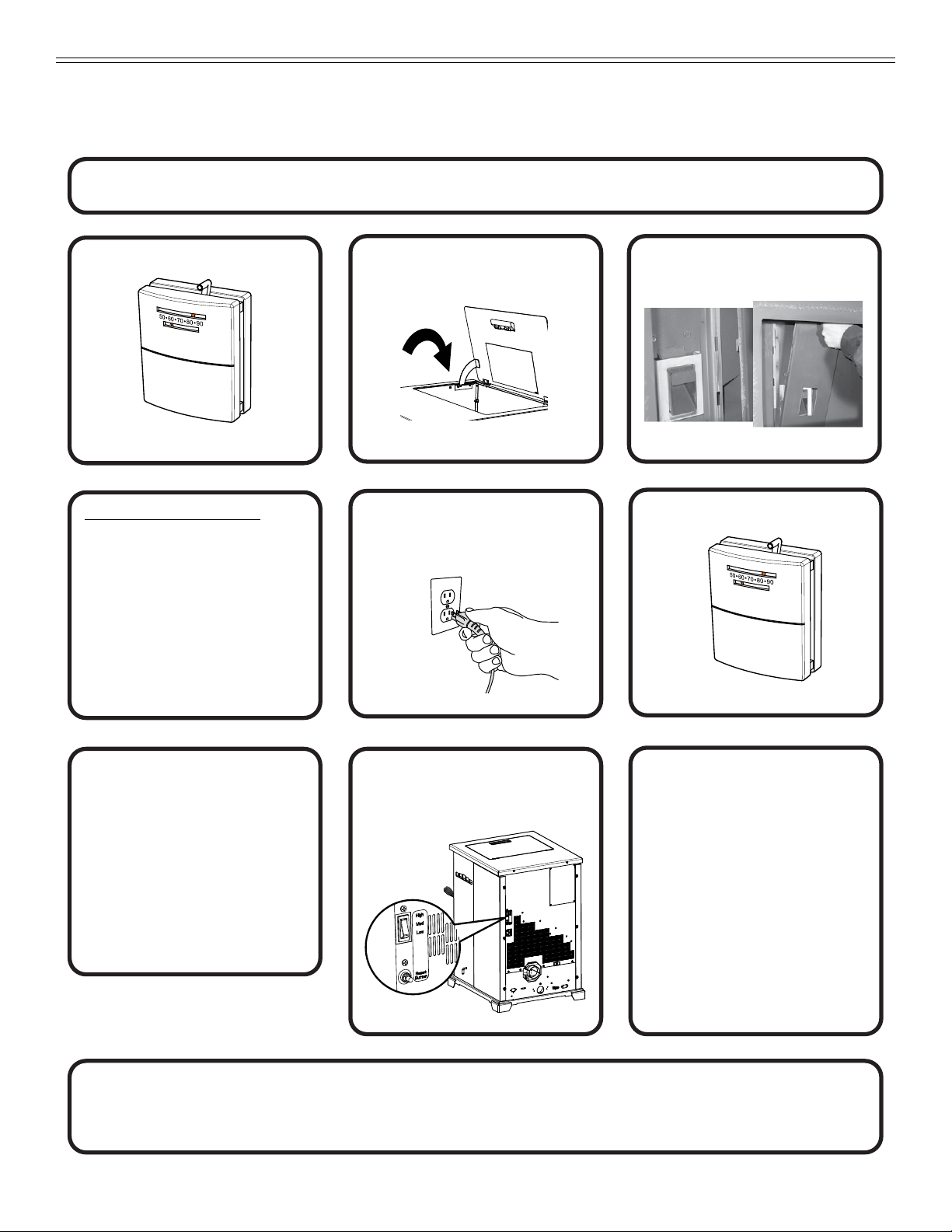
G. Hopper Lid and Hopper Switch
Hopper Lid LatchHopper Lid Latch
Hopper Switch
Hopper Switch
Control Box
Junction Box
Red Call Light
Fuse
Convection
Blower
LOCATED BEHIND LEFT SIDE PANELS
1. Lift up the hopper lid; now you can ll the hopper
with fuel.
2. The hopper switch is designed to shut down the feed
motor when the hopper lid is open. Leaving the lid open
too long can cause the re to go out (Figure 11.1).
NOTE: The hopper switch is activated by a magnet
attached to the Hopper Lid.
Figure 11.1
6. The fuel feed system and the igniter should now be on.
7. For your rst re it will be necessary to press the reset
button once approximately 2 minutes after start up
and again in 5 minutes. Reset as needed or every 60
seconds until pellets begin to drop into re pot. This will
ll the feed system and allow the appliance to begin
dropping pellets. Or you can put a handful of pellets
in the re pot to speed up the process. The appliance
will continue to run as long as the thermostat is calling
for heat.
8. Once the appliance has ignited, let it burn for
approximately 15 minutes, then set the thermostat to
the desired room temperature. Adjust the heat output
control switch to the desired setting.
H. Starting Your First Fire
CAUTION
Odors and vapors released during initial operation.
• Curing of high temperature paint.
• Open windows for air circulation.
Odors may be irritating to sensitive individuals.
1. A thermostat is required for proper operation of this
appliance. If you have to adjust the feed rate after
you have started the re, most of the pellets in the
hopper will need to be removed so start out with lling
the hopper approximately 1/4 full at this time. Set the
thermostat to its lowest setting and plug the power cord
into nearby outlet.
2. The exhaust blower will stay on for approximately 18
minutes even though the thermostat is not calling for
heat. This is normal.
3. Locate the heat output control switch mounted on
the back of the appliance in the upper left corner
(Figure 10.1 on page 10).
4. Turn it to the “high” setting by pushing the top of the
control switch in and then adjust the thermostat to its
highest setting.
5. Look through the hole in the left lower side panel and
you will see the red call light on the control box will
be on (Figure 11.2). This indicates the thermostat is
calling for heat.
Figure 11.2
11 04/217074-804F
Page 12

I. Fire Characteristics
A properly adjusted re with the heat output control
switch set on “high” has a short active ame pattern
that extends out of the repot approximately
4 to 8 inches (102 to 203mm).
If the re has tall ames with black tails and seems
somewhat lazy, the feed rate will need to be reduced. This
is done by sliding the fuel adjustment control rod down,
which will reduce the feed (Figure 12.2).
If the re is not 4 to 8 inches (102 to 203mm) tall, slide
the fuel adjustment control rod up to increase the feed. A
medium and low setting will give a shorter ame. The ame
will rise and fall somewhat. This is normal.
J. Feed Rate Adjustment Instructions
1. Loosen the thumb screw.
2. Pull the feed adjustment control rod up to increase the
feed rate and ame height or push down to decrease
the feed rate and ame height.
3. Re-tighten the thumb screw. A new stove has a break
in period. The re characteristics should be checked
again after 5 bags of pellets and adjustments made
if necessary.
K. Ignition Cycles
1. At the beginning of each ignition cycle, it is normal to
see some smoke in the rebox. The smoke will stop
once the re starts.
2. The convection blower will automatically turn on after
your appliance has been burning for approximately
10 minutes.
This blower transfers heat from your appliance into
the room, and will continue to run after the thermostat
has stopped calling for heat until the appliance has
cooled down.
3. Occasionally the appliance may run out of fuel and shut
itself down. When this happens, the red call light will be
on (Figure 11.2 on page 11).
- To restart it, ll the hopper and press the reset
button. When you press the reset button the red
call light will go out. Release the button and the
light will come back on. Continue pushing the
button once a minute until pellets begin to fall into
the re pot.
- You should see a re shortly. If not, follow the
instructions, for Starting Your First Fire on
page 11.
Figure 12.1
Figure 12.2
Feed Adjustment Rod located
inside Hopper at Front
Bottom of Hopper
Push Down
to Decrease
Pull Up to
Increase
Loosen Thumb
Screw
12 04/217074-804F
Page 13

L. Clear Space
Mantel:
Avoid placing candles and other heat-sensitive objects
on mantel or hearth. Heat may damage these objects.
NOTICE: Clearances may only be reduced by means
approved by the regulatory authority
having jurisdiction.
WARNING
Fire Risk.
Do NOT place combustible objects in front of
the appliance. High temperatures may ignite
clothing, furniture or draperies. Maintain a
minimum clearance of 3 feet (914mm) in front
of appliance.
WARNING
Fire Risk.
Keep combustible materials, gasoline and
other ammable vapors and liquids clear of
appliance.
• Do NOT store ammable materials in the
appliance’s vicinity.
• DO NOT USE GASOLINE, LANTERN FUEL,
KEROSENE, CHARCOAL LIGHTER FLUID OR
SIMILAR LIQUIDS TO START OR “FRESHEN UP”
A FIRE IN THIS Appliance.
• DO NOT BURN GARBAGE OR FLAMMABLE
FLUIDS SUCH AS GASOLINE, NAPHTHA OR
ENGINE OIL.
• DO NOT USE CHEMICALS OR FLUIDS TO START
THE FIRE.
• Keep all such liquids well away from the appliance
while it is in use.
• Combustible materials may ignite.
M. Thermostat Operation
For accurate temperature control and comfort, correct
location is very important. On new installations, the
guidelines listed in the installation manual under
Thermostat Installation should be followed as closely
as possible.
To operate thermostat simply slide the Slide Control that
is located at top of thermostat, left or right to adjust the
temperature of the room (Figure 13.1).
Slide Control
Figure 13.1
NOTE: A thermostat can only control temperature near it.
If you nd that it is uncomfortable some distance
away from the thermostat, change the setting in
order to compensate for this.
13 04/217074-804F
Page 14

N. Frequently Asked Questions
What causes my glass to become dirty?
If the glass has white ash build up it is normal and the glass should be cleaned. If it is a black soot build up airow through the unit may be
restricted. The most often cause is overdue maintenance and cleaning. See “Maintaining and Servicing Appliance” in the owner’s manual.
How can I get more heat out of the appliance?
The most often cause of diminished heat output is overdue maintenance and cleaning. See “Maintaining and Servicing Appliance” in the
owner’s manual. If this still does not help, verify the correct settings for maximum heat output. See “Feed Rate Adjustment” under “Operating
Instructions” in the owner’s manual.
What should I
do if I smell smoke or there is ash/soot coming from the appliance?
Seal exhaust venting system to the unit with High Temp silicone. Secure the venting system to the unit with at least (3) screws. All pellet
vent pipe must be secured together either by means provided by the pipe manufacturer or by (3) screws at each joint.
Why would my appliance run ne last winter but not start this fall?
It is possible that the stove was not properly prepared for the Non-burn season. See “Trouble shooting” in the owner’s manual.
Why would the metal on the inside of the appliance begin to ake?
There are some pellet mills that get their raw materials from lumber mills that purchase logs that are transported in sea water. These pellets can
have a higher salt content and cause the metals in the unit to corrode prematurely and deteriorate. If you are seeing any components inside the
rebox deteriorate it is recommended to change pellet brands immediately.
Why does only the exhaust blower run when I unplug and plug back in my appliance?
This is a Safety feature to prevent the unit from operating in an unsafe condition. Allow the unit to run and it will return to normal operation.
Is there a place to lubricate the blowers to quiet them down?
The most often cause of noisy blowers is from the impellers becoming dirty over time. See “General Maintenance & Cleaning” under
“Maintaining & Servicing Appliance” in the owner’s manual. No form of lubrication should ever need applied to the blowers.
Why are dierent components cycling on and o in my appliance at random?
The selector switch on control box may be on the wrong setting. Refer to the Reference Materials section of our owner’s manual for details.
What is the metal object with the bend in it for that came inside the plastic bag?
It is a clean-out tool used to help clean the re pot and remove any jams in the rare event they occur in the feed tube.
Why is there a black residue building up on the outside of my home?
Wind can cause this to happen. If the appliance is operating correctly very little soot should ever exit the termination cap. Also check to be sure
the venting is installed per the owner’s manual and local codes.
Do I need an outside air kit?
Outside air is required for mobile home installs and in some jurisdictions. Refer to “Listing & Code Approvals”,“ Mobile Home Installation” and “
Appliance Set-up” owner’s manual. Also refer to local building codes.
I am seeing sparks coming out of my pipe (termination cap) outside is this safe?
This is normal. As long as clearances to combustibles were followed this is safe.
My unit sounds like a freight train at times what can be done to eliminate this?
This is referred to as Rumbling. Maintenance may be needed see “Maintaining and Servicing appliance” in the owner’s manual. Decrease fuel
ow see “Feed rate adjustment” under Operating Instructions”.
Why does my unit run ne on high, but shuts down on low and medium?
Maintenance may be needed see “Maintaining and Servicing Appliance” See also “Trouble Shooting”.
Can I use another brand of wall thermostat or remote system?
Yes, any remote/wall thermostat system that does not require power from the appliance should work.
I have no power to anything. Does this unit have a circuit breaker or fuse or a reset button?
This unit has one serviceable fuse in the junction box and a reset button for the thermostat circuit.
Can I burn corn in my unit?
Corn is not an approved fuel for the CAB50-C.
I’m thinking about going green (solar power) and need to know what the power consumption is on my Unit.
CAB50 115 VAC, 60 Hz, Start 5.1 Amps, Run 3.0 Amps
Where is the serial # of my unit is located?
The serial # is located on the back of the stove.
CONTACT YOUR DEALER for additional information regarding operation and troubleshooting.
Visit www.quadrare.com to nd a dealer.
14 04/217074-804F
Page 15

3 Maintenance and Service
When properly maintained, your replace will give
you many years of trouble-free service. Contact your
dealer to answer question regarding proper operation,
troubleshooting and service for your appliance. Visit
www.quadrare.com/owner-resources to view basic
troubleshooting, FAQs, use & care videos. We recommend
annual service by a qualied service technician.
A. Proper Shutdown Procedure
Turn o the thermostat.
This pellet heater has a manufacturer-set minimum low
burn rate that must not be altered. It is against federal
regulations to alter this setting or otherwise operate this
pellet heater in a manner inconsistent with operating
instructions in this manual.
Follow the detailed instructions found in this section for each step listed as referenced in the chart below.
Shock and Smoke Hazard
• Turn down thermostat, let appliance
• Smoke spillage into room can occur if
• Risk of shock if appliance not unplugged
CAUTION
completely cool and exhaust blower must
be o. Now you can unplug appliance
before servicing.
appliance is not cool before unplugging.
before servicing appliance.
B. Quick Reference Maintenance Chart
Cleaning or Inspection
Ash Pan - Burning Wood Pellets Every 5 bags of fuel OR X
Ash Pan - Burning Alternate
Fuels
Ash Removal from Firebox
Every 1 bag of fuel OR X
More frequently depending
on the fuel type or ash build-upOR X
Frequency Daily Weekly
Every 2
Weeks
Monthly Yearly
Blower, Combustion (Exhaust)
Blower, Convection
Door Latch Inspection Prior to heating season OR X
Firebox - Prepare for Non-Burn
Season
Fire pot - Burning Softwood
Pellets
Fire pot - Burning Hardwood
Pellets
Glass
Heat Exchanger & Drop Tube Every 1 ton of fuel OR X
Hopper
Top Vent Adapter
Venting System
Table 15.1
More frequently depending
on the fuel type
More frequently depending
on the operating environment
At end of heating season OR X
Every 5 bags OR X
Every 3 bags OR X
When clear view of re pot
becomes obscured
Every 1 ton of fuel or when
changing fuel types
More frequently depending
on ash build-up
More frequently depending
on the fuel type
OR X
OR X
OR X
OR X
OR X
OR X
NOTICE: These are recommendations. Clean more frequently if you encounter heavy build-up of ash at
the recommended interval or you see soot coming from the vent. Not properly cleaning your
appliance on a regular basis will void your warranty.
15 04/217074-804F
Page 16

Firepot Cleaning Rod
C. General Maintenance
Clinker
1. Types of Fuel
Depending on the type of fuel you are burning will dictate
how often you have to clean your re pot.
If the fuel you are burning has a high dirt or ash content,
it may be necessary to clean the re pot more than once
a day.
OPEN position: light
color painted area visible
Dirty fuel will cause clinkers to form in the re pot. A clinker
is formed when dirt, ash or a non-burnable substance is
heated to 2000°F (1093°C) and becomes glass-like. See
section on High Ash Fuel Content Maintenance on
page 20 in this section for more details on fuels with high
ash content.
Figure 16.1 - Clinker
2. Cleaning Fire pot with Cleaning Rod & Fire pot
Clean-Out Tool;
• Frequency: Daily or more often as needed
• By: Homeowner
a. The appliance must be in complete shutdown and
cool and the exhaust blower o. If you are just
cleaning the re pot, there is no need to unplug
the appliance.
b. Locate the re pot cleaning rod on the right side
of the appliance (Figure 16.2). When you pull the
cleaning rod straight out it will slide open the repot
oor to allow the ashes to be deposited in the ash
drawer. You will see the light color painted area on
the cleaning rod to let you know the rod is in OPEN
position (Figure 16.3).
c. Pull the re pot cleaning rod OUT and IN a couple
of times to help shake debris loose. If the rod is
hard to pull, it may be necessary to use your re
pot clean-out tool to chip away material that has
built up on the bottom plate of the re pot and to
push out any clinkers while in the open position.
d. To close the re pot oor: slightly raise the cleaning
rod and then push it back into place. If you have
closed the cleaning rod properly (pushed all the
way in) you will not see any of the light color
painted area (Figure 16.3).
e. Always have the ash drawer in place before pulling
the re pot cleaning rod, otherwise the ashes will
fall down and ll the outside air opening and the
appliance will produce soot out of the exhaust and
will aect eciency.
Lift up and push closed
CLOSED position: no
light color paint is visible
Figure 16.2 Figure 16.3
WARNING
Fire Risk
• NEVER pull repot cleaning rod out when
appliance is operating.
• Cleaning Rod MUST be completely
pushed in before operating appliance.
• Hot pellets may fall into ash pan and start
a re or mis-starts due to lack of vacuum.
3. Ash Removal from Firebox
• Frequency: Weekly or more frequently depending on
ash build-up.
• By: Homeowner
a. There must not be any hot ashes in the rebox
during cleaning so allow the appliance to
completely cool. The rebox ash should be
removed every time the exhaust path is cleaned.
Frequent cleaning of the ash in the rebox will
help slow down the build-up of ash in the exhaust
blower and vent system.
b. Vacuum out the rebox thoroughly on both sides
of the rebox and the oor and ceiling. The ash
drawer should be emptied every time you clean the
rebox. Remember to place the ash and debris into
a metal or non-combustible container (See section
on Disposal of Ashes on page 17).
c. Always have the ash drawer in place before pulling
the re pot cleaning rod, otherwise the ashes will
fall down and ll the outside air opening and the
appliance will produce soot out of the exhaust and
will aect eciency.
WARNING
Burn Risk
• NEVER remove ash drawer while
appliance is operating.
16 04/217074-804F
Page 17

Pull out Ash Drawer and
dispose of ashes in
non-combustible container
Ash Drawer
4. Cleaning Ash Drawer
• Frequency: Weekly or every 5 bags of fuel
• By: Homeowner
a. There must not be any hot ashes in the ash drawer
when you empty it, so allow the appliance to
completely cool.
b. Locate the ash drawer underneath the re pot.
Slide the ash drawer straight out. Empty into a
non-combustible container and re-install the ash
drawer. See section on Disposal of Ashes on
page 17.
c. Always have the ash drawer in place before pulling
the re pot cleaning rod, otherwise the ashes will
fall down and ll the outside air opening and the
appliance will produce soot out of the exhaust and
will aect eciency.
6. Cleaning the Exhaust Path, Baes & Drop Tube
• Frequency: Monthly or every 25 bags or more
frequently depending on ash build-up.
• By: Homeowner
a. Appliance must be completely cool.
b. Open the door and remove the center bae rst
and then the right and left baes. See section
on Bae Replacement instructions on page 26.
Thoroughly vacuum the exhaust path and drop
tube and continue throughout the rest of the
rebox. Also vacuum the front and back of the
baes.
c. Also vacuum the combustion blower impellers or
use a soft brush to remove any ash build-up.
Replace the right and left baes and then the center bae
and close and latch the door.
Baffles Removed
Baffles Removed
Figure 17.1
5. Disposal of Ashes
• Frequency: As needed
• By: Homeowner
Ashes should be placed in a metal container with a tight-
tting lid. The closed container of ashes should be placed
on a non-combustible oor or on the ground, well away
from all combustible materials, pending nal disposal.
If the ashes are disposed of by burial in soil or otherwise
locally dispersed, they should be retained in the closed
container until all cinders have been thoroughly cooled.
WARNING
Disposal of Ashes
• Ashes should be placed in metal container
with tight tting lid.
• Ashes should be retained in closed
container until all cinders have thoroughly
cooled.
Exhaust Path and
Drop Tube
Drop Tube
Figure 17.2
Exhaust Path and
Blower Impellers
Blower Impellers
7. Cleaning the Hopper
• Frequency: Monthly or after burning 50 bags of fuel
• By: Homeowner
After burning approximately 50 bags of fuel you will need to
clean the hopper to prevent sawdust build-up.
A combination of sawdust and pellets on the bottom end of
the auger reduces the amount of fuel supply to the re pot.
This can result in nuisance shutdowns and mis-starts.
a. The appliance must be in complete shutdown.
Allow the appliance to completely run out of pellets
and cool down.
b. Empty the hopper of any remaining pellets.
c. Vacuum the hopper and feed tube.
NOTE: Hearth & Home Technologies recommends to
use a heavy duty vacuum cleaners specically
designed for solid fuel appliance cleaning.
17 04/217074-804F
Page 18

8. Soot and Fly Ash: Formation & Need for Removal in
Locknut
Door Cross Section
(example)
Latch Cam
Spacing
Washers
Square Key
Door Handle
Spring
Handle
Exhaust Venting System.
• Frequency: Yearly or more frequently depending on
ash build-up.
• By: Qualied Service Technician/Homeowner
Be sure the appliance is allowed to cool, has been
unplugged and the exhaust blower is o.
The products of combustion will contain small particles
of y ash. The y ash will collect in the exhaust venting
system and restrict the ow of the ue gases.
At start-up if there is incomplete combustion, or if there is
a shutdown or incorrect operation of the appliance it will
lead to some soot formation. This will collect in the exhaust
venting system.
The venting (chimney) system may need to be cleaned at
least once a year or more often depending upon the quality
of your fuel or if there are any horizontal pipe sections.
Ash will build up more quickly in the horizontal sections
and elbows.
9. Door Handle Inspection
• Frequency: Monthly or prior to heating season
• By: Homeowner
The gasket between the glass and rebox should be
inspected periodically to make sure there is a good seal.
Check door handle for smooth cam operation.
10. Cleaning the Glass
• Frequency: When clear view of the re pot becomes
obscure
• By: Homeowner
a. Appliance must be completely cool before
cleaning glass.
b. Vacuum y ash from glass and door rope.
c. Use a damp paper towel or any non-abrasive glass
cleaner. Wipe o with dry towel.
CAUTION
Handle glass assembly with care.
When cleaning glass:
• Avoid striking, scratching or
slamming glass.
• Do NOT clean glass when hot.
• Do NOT use abrasive cleaners.
• Refer to maintenance instructions.
WARNING
Handle glass with care.
• Inspect the gasket to ensure it
is undamaged.
• Do NOT strike, slam or scratch glass.
• Do NOT operate appliance with glass
assembly removed.
Figure 18.1
11. Cleaning Exhaust Blower - Requires No Lubrication
• Frequency: Yearly or more frequently depending on
ash build-up
• By: Homeowner or Qualied Service Technician
a. Be sure the appliance is allowed to cool, has been
unplugged and the exhaust blower is o.
b. Follow the directions for cleaning the exhaust path
found on page 17.
c. If unable to thoroughly clean the blower through
this access, follow section on Side Curtain
Replacement on page 24 to remove right side
from the appliance obtain direct access to the
exhaust blower.
d. Vacuum the blower’s impellers. Use care not to
bend or damage the blower ns.
NOTE: Hearth & Home Technologies recommends to
use a heavy duty vacuum cleaners specically
designed for solid fuel appliance cleaning.
18 04/217074-804F
Page 19

Clean-Out
Cover
12. Cleaning Convection Blower - Requires No
Lubrication
• Frequency: Yearly or more frequently depending on
Dust/Dirt build-up
• By: Homeowner or Qualied Service Technician
a. Be sure the appliance is allowed to cool and has
been unplugged.
b. Follow section on Side Curtain Replacement on
page 24 to remove left side from the appliance to
obtain direct access to the convection blower.
c. Sweep or vacuum out any build-up. Use a brush or
compressed air to loosen dirt if needed.
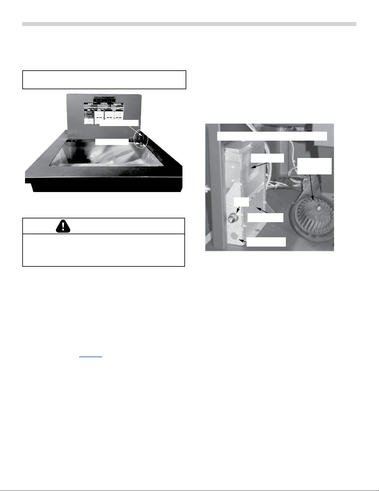
13. Cleaning the Top Vent Adapter
• Frequency: Yearly or more frequently depending on
ash build-up
• By: Homeowner
a. The appliance must be in complete shutdown
and the exhaust blower should be o. Allow the
appliance to completely cool down.
b. Open the clean-out cover (Figure 19.1).
c. Sweep or vacuum out any ash build-up.
14. Preparing Firebox for Non-Burn Season
• Frequency: Yearly
• By: Homeowner
a. Be sure the appliance is allowed to cool, has been
unplugged and the exhaust blower is o.
b. Remove all ash from the rebox and
vacuum thoroughly.
c. Paint all exposed steel, including cast-iron.
— Purchase paint from your local dealer.
— Must use a high-temperature paint made
specically for heating appliances.
Figure 19.1
19 04/217074-804F
Page 20

D. High Ash Fuel Content Maintenance
• Frequency: As needed
• By: Homeowner
Poor quality pellet fuel, or lack of maintenance, can create
conditions that make the re pot ll quickly with ashes
and clinkers.
This condition makes the appliance susceptible to
overlling the re pot with pellets which may result in
smoking, sooting and possible hopper res. Figure 20.1
shows an example where the re pot overlls, pellets
back up into the feed tube and ash has accumulated in
the rebox.
An inecient and non-economical method of burning of fuel
caused by poor quality pellet fuel is shown in Figure 20.2.
Incorrect Flame Height
Tall, Lazy Flame
Tall, Lazy Flame
Orange in Color
Orange in Color
The correct ame size when good quality, premium pellet
fuel is burned is shown in Figure 20.3.
If the ash buildup exceeds the half way point in the re pot
IMMEDIATE ATTENTION AND CLEANING IS REQUIRED.
WARNING
Fire Risk
• High ash fuels, or lack of maintenance,
can cause the re pot to overll. Follow
proper shutdown procedure if ash buildup
exceeds halfway point in re pot.
• Failure to do could result in smoking,
sooting and possible hopper res.
Pellets Back-up in Feed Tube
Pellets Back-up in Feed Tube
Firepot Overfills
Firepot Overfills
Ash build-up in FireboxAsh build-up in Firebox
Figure 20.1
Figure 20.2
Correct Flame Height
Yellow/White in Color
Figure 20.3
E. Soot or Creosote Fire
Establish a routine for the fuel, wood burner and ring
technique. Check daily for creosote build-up until
experience shows how often you need to clean to be
safe. Be aware that the hotter the re the less creosote
is deposited, and weekly cleaning may be necessary in
the mild weather even though monthly cleaning may be
enough in the coldest months. Contact your local municipal
or provincial re authority for information on how to handle
a chimney re.
In the event of a soot or creosote re, close the rebox
door, exit the building immediately and contact the
proper re authorities.
DO NOT under any circumstances re-enter
the building.
20 04/217074-804F
Page 21

4 Troubleshooting Guide
With proper installation, operation, and maintenance your appliance will provide years of trouble-free service. If you do
experience a problem, this troubleshooting guide will assist a qualied service person in the diagnosis of a problem and the
corrective action to be taken. This troubleshooting guide can only be used by a qualied service technician.
Symptom Possible Cause Corrective Action
Plug in appliance No response.
Call light on. No re.
No fuel in re pot.
Call light on. No re.
Partially burned fuel in
re pot.
Call light on. No re.
Unburned pellets in
re pot.
Slow or smoky start-up.
Table 21.1
No current to outlet.
7 amp fuse defective.
#3 snap disc tripped or defective.
Control box defective.
Out of fuel.
#2 snap disc may be defective.
Vacuum switch not closing, no vacuum.
Control box defective.
Fire pot clean-out plate not closed.
Fire pot is dirty (missed ignition).
Fire pot clean-out plate not closed.
Fire pot is dirty.
Ignition hole blocked.
Igniter not working.
Control box defective.
Fire pot clean-out plate not closed.
Fire pot is dirty.
Excessive amount of fuel at start-up.
Check circuit breaker at service panel.
Replace fuse.
Reset or replace snap disc.
Replace control box.
Check hopper. Fill with fuel.
Replace snap disc.
Check exhaust blower is plugged in
and operating.
Check vacuum switch is plugged in.
Check vacuum hose is in good condition,
clear and connected at both ends.
Check thermocouple is in good condition
and plugged in properly.
Make sure venting system is clean.
Make sure front door is closed.
Replace control box.
Check that re pot clean-out plate is fully
closed.
Clean re pot. Make sure there is no clinker
in the re pot.
Clinkers may have to be broken up with re
pot scraper tool or other means.
Check that re pot clean-out plate is
fully closed.
Clean re pot. Make sure there is not a
clinker in the re pot. Clinkers may have
to be pushed out of re pot with re pot
scraper tool or other means.
Scrape with solid piece of wire.
Remove ash pan to see if igniter is glowing
red on start-up.
Check igniter wires for good connection.
Replace igniter using 1/4 inch male /female
spade connectors.
Replace control box.
Check that re pot clean-out is fully closed.
Clean re pot. Make sure there is not a
clinker in the re pot. Clinkers may have to
pushed out of re pot with re pot scraper
tool or other means.
Reduce feed rate using feed rate adjustment
control rod located inside hopper.
21 04/217074-804F
Page 22

Symptom Possible Cause Corrective Action
Slow or smoky start-
up (Cont’d)
Feed system fails
to start.
No call light. Appliance
does not begin
start sequence.
Dirty exhaust and/or venting system.
Out of fuel.
#2 snap disc may be defective.
Vacuum switch not closing. No vacuum.
Feed system jammed or blocked.
Feed spring not turning with feed motor.
Feed motor defective or not plugged in.
Thermostat not set to a high enough
temperature.
Snap Disc #3 tripped.
No power.
Fuse blown.
Connections at thermostat and/or appliance not
making proper contact.
Defective thermostat or thermostat wiring.
Check for ash build up in appliance,
including behind rear panels, rebox, heat
exchanger, exhaust blower and venting.
Check hopper, ll with fuel.
Replace snap disc. Firebox door must be
closed securely.
Check exhaust blower is plugged in and
operating.
Check vacuum switch is plugged in. Check
vacuum hose is in good condition, clear and
connected at both ends.
Check thermocouple is in good condition
and plugged in properly.
Make sure venting system is clean.
NOTE: High winds blowing into the venting
system can pressurize the rebox
causing loss of vacuum.
Empty hopper of fuel. Use a wet/dry vacuum
cleaner to remove remaining fuel, from
hopper, including feed tube.
Check feed chute for obstructions.
Loosen 2 screws and jiggle feed assembly.
Check that set screw is tight on feed spring
shaft at end of feed motor.
Check connections on feed motor, replace if
defective.
Adjust thermostat above room temperature.
Reset snap disc.
Connect to power.
Replace fuse.
Check connections at thermostat
and appliance.
Replace thermostat or wiring.
NOTE: To test thermostat and wiring, use
a jumper wire at the thermostat
block on the appliance to by-pass
thermostat and wiring.
Control box defective.
Appliance fails to
shut o.
Table 22.1
Call light on.
22 04/217074-804F
Replace control box.
Turn thermostat o.
If call light does not go out, disconnect
thermostat wires from appliance. If call
light does go out, thermostat or wires
are defective.
Page 23

Symptom Possible Cause Corrective Action
No call light.
Defective control box.
Convection blower fails to
start.
Exhaust blower fails to
start or does not shut o.
Large, lazy ame, orange
color. Black ash on glass.
#1 snap disc defective.
Blower not plugged in.
Blower is defective.
Control box is defective.
Blower not plugged in.
Blower is clogged with ash.
Blower is defective.
Control box is defective.
Dirty appliance.
Poor fuel quality, high ash content.
Fire pot clean-out plate not
completely closed.
Excessive amount of fuel.
Low ame.
Replace snap disc.
Check that blower is plugged into
wire harness.
Replace blower.
Replace control box.
Check that blower is plugged into wire
harness.
Clean exhaust system.
Replace blower.
Replace control box.
Clean appliance, including re pot, heat
exchangers and venting system. Remove
stainless steel bae from rebox to clean
ash from on top of bae. Clean behind rear
brick panels. Change fuel brand to premium.
Check that re pot clean-out plate is
fully closed.
Reduce feed rate using feed rate adjustment
control rod located inside hopper.
Increase feed by opening feed rate
adjustment control rod located inside
hopper.
Nuisance shutdowns.
Appliance calls for heat.
Call light illuminates.
Exhaust blower starts.
No feed or igniter.
Table 23.1
Sawdust buildup in hopper.
Feed motor is reversing.
Defective thermocouple.
Defective control box.
Fire pot more than 1/2 full
Thermocouple is defective or not properly
plugged in.
Defective control box
Clean hopper, see page 17.
Check for good connections between feed
motor and wire harness.
Replace thermocouple.
Replace control box.
See page 20 for detailed instructions for
“High Ash Fuel Content Maintenance”.
Check connections on thermocouple or
replace if defective.
A ashing yellow light on the control box
indicates a problem with the thermocouple.
Replace control box.
23 04/217074-804F
Page 24

5 Service Parts Replacement
Loosen Screws,
Do Not Remove.
Nylon Wire Retainer
Wing Screw
Hold Down Bracket
Spade
Connectors
Locating Tab
A. Side Curtain Replacement
1. Using a #2 Phillip Head screwdriver, a 3/8 inch wrench
or a 3/8 Inch socket, loosen the three (3) bolts from the
back side of the appliance (Figure 24.1).
2. Remove side curtain by lifting up and out of the slots
(Figure 24.2).
NOTE: If conducting other service part replacements, do
it at this time:
- Right side: Feed motor, vacuum switch, and
combustion blower (Figure 30.3 on page 30).
- Left side: Control box, convection blower,
fuse, junction box, and red call light
(Figure 30.2 on page 30).
3. Add new side curtain in reverse order.
B. Convection Blower Replacement
1. Turn down the thermostat, let appliance completely
cool and then unplug appliance before servicing.
2. The convection blower is located on the oor at the
rear of the appliance.
3. Follow section on Side Curtain Replacement on
page 24 to remove left side from the appliance.
4. Release blower wires from the nylon wire retainer if
applicable. This appliance has 1 black and 1 white wire
coming from the blower.
5. Remove the wing bolt and move the blower and hold-
down bracket toward the back of the appliance to
release the locating tab (Figure 24.3). Pull the blower
out from under the convection plenum. Slide the blower
out of the appliance. Disconnect the wires from the
spade connectors at this time (Figure 24.4).
6. Return wires to nylon wire retainer. Make sure wires
do not contact any moving parts or touch any surfaces
that may become hot (Figure 24.4).
Figure 24.1
Left Panel
Figure 24.2
Figure 24.3
Lift Up and
Out of Slots
Figure 24.4
24 04/217074-804F
Page 25

C. Exhaust Blower Replacement
Exhaust Blower
Snap Disc #1
Snap Disc #3
Snap Disc #2
Remove ScrewRemove Screw
Snap Disc Bracket
Snap Disc Bracket
1. Turn down the thermostat, let appliance completely
cool and then unplug appliance before servicing.
2. Follow section of Side Curtain Replacement on
page 24 to remove right side from the appliance.
3. Disconnect two (2) white wires from the white and blue
wires of the exhaust blower.
4. There is a removable plate on the exhaust blower.
Depending on the model, use a 1/4 inch socket, or
1/4 inch Nut Driver or #2 Phillips Head screw driver to
loosen the six (6) screws in the keyhole shaped holes
and rotate the plate. It is only necessary to loosen
screws (Figure 25.1).
5. Remove the exhaust blower and gasket.
6. Check for degradation on the gasket and replace if
necessary using the gasket included in the kit.
7. Re-install in reverse order.
Snap Disc #2 - Fuel Delivery Interrupt
1. Turn down thermostat, let appliance cool completely if
running. Then unplug appliance before servicing.
2. Follow section on Side Curtain Replacement on
page 24 to remove right side from the appliance.
3. Snap disc #2 is located on the convection plenum
in the center of the appliance above the convection
blower (Figure 25.2).
4. It has a black wire and an orange wire attached to it
with 1/4 inch female spade terminals.
5. Disconnect the two wires from the snap disc. Using
a #2 Phillips screwdriver, remove the two screws
securing the snap disc to the appliance.
6. Re-install in reverse.
Snap Disc #3 - Feed Motor - Manual Reset
1. Turn down thermostat, let appliance cool completely if
running. Then unplug appliance before servicing.
2. Follow section on Side Curtain Replacement on
page 24 to remove right side from the appliance.
3. Snap disc #3 is located on the bracket on the feed tube
near the feed motor (Figure 25.2).
4. It has a two gray wires attached to it with 1/4 inch
female spade terminals.
5. The locating bracket is attached to the feed tube with
an 8 X 32 inch wing nut. Remove the wing nut to
detach the bracket from the feed tube.
6. Disconnect the two wires from the snap disc.
7. Using a #2 Phillips screwdriver, remove the screw
securing the snap disc to the bracket (Figure 25.3).
8. Re-install in reverse.
Figure 25.1
D. Snap Disc #1, #2, #3 Replacement
Snap Disc #1 - Convection Blower
1. Turn down thermostat, let appliance cool completely if
running. Then unplug appliance before servicing.
2. Follow section on Side Curtain Replacement on
page 24 to remove right side from the appliance.
3. Snap disc #1 is located on the convection plenum
below the feed motor (Figure 25.2).
4. It has two purple wires attached to it with 1/4 inch
female spade terminals.
5. Disconnect the two wires from the snap disc. Using
a #2 Phillips screwdriver, remove the two screws
securing the snap disc to the appliance.
6. Re-install in reverse.
Figure 25.2
25 04/217074-804F
Figure 25.3
Page 26

E. Igniter Replacement
Firepot
Igniter
Igniter
Chamber
Thermocouple &
Thermocouple Cover
Thumb
Screw
Firepot Cleaning Rod
Igniter Wires
MUST BE ROUTED
Through Wire Retainer Hook
Use handle at top
of center baffle to
pull up and then
towards you.
Lift up to
remove hooks
from slots
Remove left baffle
Remove right baffle
Lift up to remove
hooks from slots
1. Shut down the appliance by turning down the
thermostat and let the appliance completely cool down.
After the appliance has cooled down, unplug it and
remove the ash drawer.
2. The wire leads to the igniter are connected to the wire
harness with 1/4 inch male / female spade connectors.
3. Follow section on Side Curtain Replacement on
page 24 to remove right side from the appliance to
expose the spade connectors.
4. Disconnect the spade connectors and remove the
igniter from the chamber. Loosen thumb screw and
slide igniter out.
5. Install new igniter into the chamber and tighten thumb
screw. The wires MUST route through the wire retainer
hook and then re-connect the wires to the two (2) leads
with the spade connectors (Figure 26.1).
6. Double check that the igniter wires are clear of any
movement, i.e. ash drawer, re pot cleaning rod, etc.
7. Re-install the ash drawer and side panel and
re-connect the power.
F. Bae Replacement
1. Shut down the appliance by turning down the
thermostat and let the appliance completely cool down.
2. Remove the center bae rst by using the handle at
the top of the bae and pull up and then towards you.
The hooks on the bae will slide out of the slots in the
bracket (Figure 26.2).
3. Remove the left bae and then the right bae
by pulling up and then towards you. The left
and right baes have similar hooks and slots
(Figures 26.3 and Figure 26.4).
4. Re-install the baes in reverse order. Be careful to
insert the hooks in their respective slots. Be sure the
baes are completely secure/seated (close, if not
touching, the rebox oor).
Figure 26.1
Figure 26.2
Figure 26.3
26 04/217074-804F
Figure 26.4
Page 27

G. Glass Replacement
1
2
3
4
Glass Assembly
Remove the 4
brackets outlined
in the diagram
1. Open the door from the appliance by lifting door o of
hinge pins and lay on a at surface face down.
2. Using a Phillips Head screw driver, remove the 4
brackets and set aside (Figure 27.1).
3. Remove old glass and replace with the new glass.
4. Re-install the brackets using the same screws.
Figure 27.1
WARNING
• Glass is 5mm thick high temperature
heat-resistant ceramic glass.
• DO NOT REPLACE with any other
material.
• Alternate material may shatter and
cause injury.
27 04/217074-804F
Page 28

6 Reference Materials
A. Component Functions
1. Control Box
a. The control box is located on the lower left side of
the appliance, behind the lower left side panel and
above the junction box.
b. There is a light located inside of the control box.
The internal light will turn green when the appliance
has reached a temperature of 200°F (93°C) in
the re pot and will turn red when it reaches
600°F (315°C).
c. There is also an internal blue light located in the
control box. When you plug in the appliance the
blue light will automatically start blinking. This
model it should blink 2 times.
To set your control board on the correct number:
• Unplug the appliance.
• Using #2 Phillips screw driver, 3/8” wrench, or 3/8”
socket loosen the three screws that hold the right upper
and lower side panels in place. You do not need to
remove the screws. Remove side panels by lifting up
and out.
• Use a #2 Phillips screw driver to remove the control
box retainer bracket and lift control box out of the
junction box.
• Using a ¼ inch at head screw driver turn the rotary
switch until the desired number is showing on the dial.
• Re install control box and plug in appliance.
• To conrm your selection is correct count the number of
times the blue light ashes.
Example: If you are on setting 2 the control box will ash 2
times every 10 seconds for 1 minute.
Your CAB50-C is set to #2 (2 ashes) (Figure 28.1).
When describing the location of a
component, it is always AS YOU FACE THE
FRONT OF THE APPLIANCE.
2. Convection Blower
The convection blower is mounted at the bottom rear of
the appliance. There are 2 impellers, one on each side
of the motor. The convection blower pushes heated air
through the heat exchange system into the room.
3. Exhaust Blower
The exhaust blower is mounted on the right side of the
appliance. The exhaust blower is designed to pull the
exhaust from the appliance and push it out through the
venting system.
4. Feed System
The feed system is located on the right side of the
appliance and can be removed as an entire assembly.
The assembly includes the feed motor, mounting
bracket, bearing and feed spring (auger). The hollow
feed spring (auger) pulls pellets up the feed tube from
the hopper area and drops them down the feed chute
into the re pot.
5. Fire pot
The re pot is made of high quality ductile iron and has
a cleaning pull-out rod. The oor of the re pot opens
for cleaning when you pull out the rod. Be sure that the
oor returns to a completely closed position or your
appliance will not operate properly.
6. Fuse
The fuse is located on the side of the junction box
above to the red call light. The fuse will blow should a
short occur and shut o power to the appliance.
7. Heat Output Switch
Screwdriver
Slot
Figure 28.1 - Rotary Switch
NOTE: Do NOT open the control box. This will void the
warranty. If you need to plug in or remove the
control box you must rst unplug the appliance.
28 04/217074-804F
8. Hopper Switch
9. Igniter
10. Junction Box And Wiring Harness
The heat output switch is located on the upper right
back panel. The function of the heat output switch is to
regulate the burn rates; low, medium and high settings.
The hopper switch is located in the upper right hand
corner of the hopper. This switch is designed to shut
down the feed motor whenever the hopper lid is
opened.
The igniter is mounted on the base of the re pot.
Combustion air travels over the red hot igniter creating
super heated air that ignites the pellets.
The junction box is located on the lower left side of the
appliance, behind the left side panel. The junction box
and wiring harness are replaced as one component.
Page 29

11. Power Supply
1
B
3/C
D
5/E
F
7/H
14
8
K
10
M
12/N
P
S
M
M
M
NL
G
Thermocouple
Heat Output
Switch
Thermostat
Block
Vacuum
Switch
Snap
Disc #2
Capacitor Feed
Motor
Snap
Disc #1
Convection
Motor
Combustion
Blower
Call
Light
Reset
Button
Snap
Disc #3
Fuse
Igniter
Green
Yellow
Red
Red
Red
Orange
Orange
White
Black
Black
Black
Yellow
Red
Purple
Grey
Grey
Blue
Black
Black
Blue
Hopper
Switch
The power outlet is located behind the control box on
the back of the appliance, lower left corner. Check the
wall receptacle for 120 volt, 60 Hz (standard current).
Make sure the outlet is grounded and has the correct
polarity. A good surge protector is recommended.
12. Red Call Light
The red call light is on the side of the junction box,
below the fuse. The function of the red call light is to
indicate that the thermostat is calling for heat.
13. Reset Button
The reset button is located on the back of the appliance
in the upper right corner below the heat output control
switch. The function of the button is to momentarily
open the thermostat circuit, which restarts the system.
17. Snap Disc #2 (Fuel Delivery Interrupt) 175°F
Snap disc #2 is located on the center of the convection
plenum above the convection blower. There is an
orange and a black wire connected to it. This snap
disc will turn o the feed system which will turn o the
appliance if an over re condition should occur or if the
convection blower should fail to operate. If this occurs
you will have to manually reset the snap disc.
18. Snap Disc #3 (Back Burn Protector) 250°F
Snap disc #3 is mounted on the back of the auger tube
in the center of the appliance and has a reset button.
There are two gray wires connected to it. To access it
remove the right side panel. If the re tries to burn back
into the feed system or push exhaust up the feed tube,
this snap disc will shut the entire system o. This disc
must be manually reset.
14. Thermocouple
The thermocouple is located on top of the repot inside
the thermocouple cover (ceramic protection tube). The
thermocouple sends a millivolt signal to the control box
indicating the preset temperatures of the green and red
lights have been obtained.
15. Thermostat
The appliance is designed to run on a 12 volt AC
thermostat. The heat anticipator should be set on the
lowest setting available.
16. Snap Disc #1 (Convection Blower) 110°F
Snap disc #1 is located on the right side of the
appliance behind the right side panel. There are 2
purple wires connected to it. This snap disc turns the
convection blower on and o as needed. Power is
always present at snap disc #1.
19. Vacuum Switch
The vacuum switch is located on the lower right side
of the appliance behind right side panel. There are
two red wires attached to it. This switch turns the feed
system on when vacuum is present in the rebox. The
vacuum switch is a safety device to shut o the feed
motor if the exhaust or the heat exchanger system is
dirty or plugged or if the rebox door is open.
20. Wiring Harness
See Figure 29.1 below.
Figure 29.1
29 04/217074-804F
Page 30

Convection
blower
LOCATED BEHIND LEFT SIDE PANELS
Control Box
Junction Box
Red Call Light
Fuse
LOCATED BEHIND RIGHT SIDE PANELS
Feed Motor
Vacuum Switch
Combustion Blower
Power Outlet
Terminal Block
Center 2 Screws for
Thermostat Wires
Back of
Appliance
Reset Button
Heat Output Switch
B. Component Locations
Figure 30.1
Figure 30.2
30 04/217074-804F
Figure 30.3
Page 31

C. Maintenance and Service Log
Date of Service Performed By Description of Service
31 04/217074-804F
Page 32

Date of Service Performed By Description of Service
32 04/217074-804F
Page 33

Date of Service Performed By Description of Service
33 04/217074-804F
Page 34

Date of Service Performed By Description of Service
34 04/217074-804F
Page 35

D. Service Parts List
Beginning Manufacturing Date: Mar 2019
R
Service Parts
CAB50-C
Pellet Cabinet Style Stove
1
2
3
4
Ending Manufacturing Date: Active
30
29
28
12
9
11
10
5
6
25
24
23
22
7
8
21
20
16
14
13
15
27
26
19
18
17
Part number list on following pages.
35 04/217074-804F
4/21
Page 36

R
Beginning Manufacturing Date: Mar 2019
Service Parts
CAB50-C
Ending Manufacturing Date: Active
IMPORTANT: THIS IS DATED INFORMATION. Parts must be ordered from a dealer or distributor. Hearth and
Home Technologies does not sell directly to consumers. Provide model number and serial number when
requesting service parts from your dealer or distributor.
ITEM DESCRIPTION COMMENTS PART NUMBER
1 Hopper Lid Assembly SRV7074-009
2 Handle, Hopper Lid SRV200-0110
3 Top Assembly SRV7074-032
#4 Door Assembly
4.1
4.2
4.3
4 Door Assembly SRV7058-014
4.1 Glass Assembly SRV7058-015 Y
4.2 Rope, Door, 3/4” X 84” 832-1680 Y
Corner Tape 1 Ft SRV560-437-9
Gasket, Glass Tape, 3/4” X 1/8” 5 Ft 832-0460 Y
4.3 Hinge Pin, 1/2” Nickel SRV430-5320
4.4 Door Handle Assembly SRV7058-030 Y
4.5 Spring Handle, 1/2” Black 250-8330 Y
4.6 Handle, Formed Door SRV7058-182
4.7
4.8
4.9
4.10
5 Bumper, Rubber
6 Bae Assembly SRV7059-026
Key Latch, Cam SRV430-1151
Washer, SAE, 3/8 (Qty 2 req) Pkg of 3 832-0990 Y
Cam Latch SRV430-1141
Nut, 2-Way Side-Lock Jam Pkg of 24 226-0100/24 Y
4.4
4.5
4.6
Pkg of 12
4.7
4.10
4.9
4.8
SRV224-0340/12 Y
Stocked at
Depot
Y
Y
#7 Thermocouple Assembly
7.1
7.2
7.3
7.1 Thermocouple Protection Tube
7.2 Half Clip 7000-321
7.3 Thermocouple 812-4470 Y
Additional Service Parts on following page.
Pkg of 10 SRV7034-186/10
SRV7034-186 Y
36 04/217074-804F
Page 37

R
Beginning Manufacturing Date: Mar 2019
Service Parts
Ending Manufacturing Date: Active
IMPORTANT: THIS IS DATED INFORMATION. Parts must be ordered from a dealer or distributor. Hearth and
Home Technologies does not sell directly to consumers. Provide model number and serial number when
requesting service parts from your dealer or distributor.
CAB50-C
ITEM DESCRIPTION COMMENTS PART NUMBER
8 Firepot Assembly SRV7034-072B Y
Gasket, Firepot SRV7034-190 Y
9 Heating Element Assembly 18” (Loop Igniter)
10 Firepot Bottom SRV7034-153 Y
11 Spring Pkg of 4 7000-513/4 Y
12 Hitch Pin Clip 3/32 Pkg of 10 7000-374/10 Y
13 Rail, Auto-Clean SRV7034-152 Y
14 Pull Rod SRV7074-141 Y
15 Ash Pan Assembly SRV7058-013
16 Latch Backing Plate SRV7058-155
17 Exhasut Combustion Blower, 70 CFM SRV7000-602 Y
18 Gasket, Exhaust Combustion Blower SRV240-0812 Y
Gasket, Combustion Blower, Round 812-4710 Y
19 Casting, Exhaust Transition 180-0190
20 Convection Blower, 220 CFM SRV7000-108 Y
21 Wire Harness SRV7058-150 Y
22 Blower Retainer SRV7058-148
23 Control Board 3 Speed SRV7058-188 Y
Pkg of 1 SRV7000-462 Y
Pkg of 10 SRV7000-462/10 Y
Stocked
at Depot
Snap discs
24
F110F-20
24 Snap Disc F110F-20 ( #1 ) SRV230-1220 Y
25 Snap Disc L175F Manual Reset ( #2 ) SRV230-1960 Y
26 Feed Assembly SRV7058-007 Y
Feed Bearing SRV7000-598 Y
Feed Motor 812-4421 Y
Feed Spring Assembly (Only) SRV7001-046 Y
Gasket, Feed Motor SRV7034-144
27 Snap Disc L250F Manual Reset ( #3 ) SRV230-1290 Y
28 Side Curtain Qty 2 req SRV7074-124
29 Vacuum Switch SRV7000-531 Y
Additional Service Parts on following page.
37 04/217074-804F
25
L175F Manual Reset
27
L250F Manual Reset
Page 38

R
Service Parts
Beginning Manufacturing Date: Mar 2019
Ending Manufacturing Date: Active
IMPORTANT: THIS IS DATED INFORMATION. Parts must be ordered from a dealer or distributor. Hearth and
Home Technologies does not sell directly to consumers. Provide model number and serial number when
requesting service parts from your dealer or distributor.
CAB50-C
ITEM DESCRIPTION COMMENTS PART NUMBER
30 Hopper Lid Magnetic Switch SRV7000-375 Y
Jumper Hopper Switch SRV7074-175 Y
Component Pack SRV7074-056
Airwash SRV7058-175
Cleanout Tool 414-1140 Y
Harness, Thermostat Wire 230-0810
Power Cord 812-1180 Y
Thermostat Mechanical 812-3760 Y
Touch Up Paint 3-42-19905
Fuse, 7 Amp, Junction Box
Hose, Vacuum, 5/32 Id 3 Ft SRV240-0450 Y
Pkg of 10
812-0380/10 Y
Hose Barb Assembly SRV229-0920
Damper, 4 Inch PEL-DAMP4
Outside Air Kit, 3” OAK-3
Outside Air Kit, 2” 811-0872
Hose, Alum Flex, 2 Inch X 3 Ft 3 Ft SRV200-0860
Outside Air Cap Assembly 7001-044
Outside Air Collar Assembly SRV7001-045
Trim Plate, Outside Air Kit 412-7100
Pull Rod Handle PULLROD-HNDL
Reset Button Assembly SRV7000-040
Smart-Batt Il
No longer available
SMARTBATT-B
Smart-Stat Il SMART-STAT-HHT
Thermostat, Programmable 811-0520
Top Vent Adapter TPVNT-5
Component Pack, TPNVT SRV7058-054
Vent Adapter, 3-4” 811-0720
Vent Adapter, 3”-6” 812-3570
Vent Adapter, 90, Cleanout TPVNT-6
Bae Center Back SRV7058-166
Stocked
at Depot
Additional Service Parts on following page.
38 04/217074-804F
Page 39

R
Service Parts
Beginning Manufacturing Date: Mar 2019
Ending Manufacturing Date: Active
IMPORTANT: THIS IS DATED INFORMATION. Parts must be ordered from a dealer or distributor. Hearth and
Home Technologies does not sell directly to consumers. Provide model number and serial number when
requesting service parts from your dealer or distributor.
ITEM DESCRIPTION COMMENTS PART NUMBER
Fastener Packs
Rivnut Repair Kit RIVNUT-REPAIR Y
Bolt, Hex Head, 1/4-20 X 1 Pkg of 10 25221A/10 Y
Guide Pin Sleeve Pkg of 25 31120/25 Y
Hurricane Screw Pkg of 40 SRV2005-861/40
Nut, 2-Wy Side-Lock Jam 3 Pkg of 24 226-0100/24 Y
Nut, Lock 1/4-20 Pkg of 25 226-0090/25 Y
Nut, Ser Flange Small 1/4-20 Pkg of 24 226-0130/24 Y
Screw 8 - 32x3/8 HWH BK Pkg of 40 SRV060-883/40
Screw Hwh Ms 1/4-20 X 3/4 Ns Pkg of 25 220-0080/25 Y
Screw, Sheet Metal #8 X 1/2 S-Grip Pkg of 40 12460/40 Y
Thumbscrew, 1/4-20 X 3/4 Pkg of 10 844-5070
Washer, 1/4 Sae Pkg of 24 28758/24 Y
Washer, Sae Pkg of 25 227-0080/25 Y
Wing Thumb Screw 8-32X1/2 Pkg of 24 7000-223/24 Y
CAB50-C
Stocked
at Depot
39 04/217074-804F
Page 40

CONTACT INFORMATION
Hearth & Home Technologies
352 Mountain House Road
Halifax, PA 17032
Division of HNI INDUSTRIES
Please contact your Quadra-Fire dealer with any questions or concerns.
For the number of your nearest Quadra-Fire dealer
log onto www.quadrafi re.com
CAUTION
DO NOT DISCARD THIS MANUAL
• Important operating
and maintenance
instructions
included.
• Read, understand
and follow these
instructions for
safe installation
and operation.
• Leave this
manual with party
responsible for
use and operation
of this appliance.
DISCARD
We recommend that you record the following pertinent
information for your heating appliance.
Date purchased/installed:
Serial Number: Location on appliance:
Dealership purchased from: Dealer Phone: 1( ) -
Notes:
DO NOT
This product may be covered by one or more of the following patents: (United States) 5341794, 5263471, 6688302, 7216645, 7047962
or other U.S. and foreign patents pending.
40 04/217074-804F
 Loading...