

Quadra-Fire BODBAY Owner's Manual
BODEGA BAY WOOD INSERT
O- T L
Tested and
Listed by
Portland
Oregon USA
OMNI-Test Laboratories, Inc.
C
US
R
Advanced Combustion Technology (ACT)
OWNER’S MANUAL
Installation and Operation
Model:
BODBAY
This manual contains instructions for Installation, Operation & Maintenance.
Please read this entire manual before you install and use your new room heater. Failure to follow
instructions may result in property damage, bodily injury, or even death.
IMPORTANT SAFETY NOTES:
1) When installing your stove, particular attention should be paid to re protection. If this room heater is not properly
installed, a house re may result. To reduce the risk of re, follow the installation instructions. Contact local building or re ofcials or authority having jurisdiction about restrictions, installation inspection and permit requirements
in your area.
2) CAUTION: Never use gasoline or gasoline-type lantern fuel, kerosene, charcoal lighter uid, or similar liquids to
start or “freshen up” a re in this heater. Keep all such liquids well away from heater while it is in use.
3) During operation, if any part of the stove starts to glow, the stove is in an overred condition. Close the air controls
completely until the glowing has stopped. OVERFIRING VOIDS YOUR WARRANTY!
4) Cool ashes should be disposed of carefully, using a metal container.
5) Do not burn wet or green wood. Store wood in a dry location.
6) DO NOT BURN GARBAGE OR FLAMMABLE FLUIDS SUCH AS GASOLINE, NAPHTHA OR ENGINE OIL. Do
not burn treated wood, or wood with salt (driftwood, etc.). Burning materials other than wood (including charcoal)
under adverse conditions may generate carbon monoxide in the home, resulting in illness or possible death.
7) Do not permit creosote or soot to accumulate excessively in the chimney or inside the rebox.
8) Check your chimney system thoroughly when installing into an existing metal or masonry chimney. Seek professional advice if in doubt about its condition.
9) Do not connect this unit to a chimney ue already serving another appliance.
10) Comply with all minimum clearances to combustibles as shown in this manual for this appliance.
11) Build re on brick rebox oor. Do not use grates, andirons or other methods to support fuel.
12) HOT WHILE IN OPERATION! Keep children, pets, clothing and furniture away. Contact can cause skin burns.
13) Do not connect to any air distribution duct or system
14) RISK OF FIRE! Do not operate with stove door open, without the rescreen, or ash removal system door open.
15) For further information refer to NFPA 211 (USA) or CAN/CSA-B365 (Canada).
16) Do not operate without fully assembling all components. Burning your stove without the legs attached (if supplied
with unit) will void your warranty, and could present a serious safety hazard
17) Do not oeprate with broken glass..
PRIOR TO FIRST FIRE: Remove all labels from glass. Clean plated surfaces with a glass cleanser and soft
cloth to prevent staining from ngerprint oils.
1445 North Highway
Colville, WA 99114-2008
SAVE THESE INSTRUCTIONS
435-1320B August 20, 2008
www.quadrare.com
BODEGA BAY WOOD INSERT
R
and Welcome to the Quadra-Fire Family!
Model:
BODEGA BAY
Serial No / Numéro De Série
OMNI-Test Laboratories, Inc.
Report #061-S-40-2
O- T L
Tested and
Listed by
Beaverton
Oregon USA
C
Made in U.S.A
.
U.S. ENVIRONMENTAL PROTECTION AGENCY - Certified to comply with July 1990 particulate emission standards.
2008 2009 2010 Jan Feb Mar Apr May June July Aug Sept Oct. Nov. Dec.
LISTED ROOM HEATER, SOLID FUEL TYPE. "For Use with Solid Wood Fuel Only."
Also for use in Mobile Home.
DO NOT REMOVE THIS LABEL
435-1330
Manufactured by:
R
HOT WHILE IN OPERATION DO NOT TOUCH,
KEEP CHILDREN AND CLOTHING AWAY.
CAUTION
:
TESTED TO:
UL 1482, ULC S628-93
Thermal Protection USA & Canada
Minimum Clearances To Combustible Material
Masonry, Heat Circulating & Zero Clearance *
USA
A Sidewall to Stove 15"
B Mantel to Stove 26"
C Top Trim to Stove 20"
D Side Trim to Stove 6"
E Hearth Extension from Glass 16"
F Hearth Extenson from Side of Insert 8"
1/2 inch (12.7mm) of k=0.84
*Zero Clearance Installations USA Only
Mantel
Hearth Extension
A
B
C
D
F
E
Insert
SideWall
Maximum Mantel Depth - 10"
Fascia or Trim
CONTACT MAY CAUSE SKIN BURNS. KEEP FURNISHINGS AND
OTHER COMBUSTIBLE MATERIAL FAR AWAY FROM THE APPLIANCE.
SEE NAMEPLATE AND INSTRUCTIONS.
1445 N. Highway, Colville, WA 99114
www.quadrafire.com
Refer to Clearances on reverse side for Canada
SAMPLE
007
US
Hearth & Home Technologies welcomes you to our tradition
of excellence! In choosing a Quadra-Fire appliance, you have
our assurance of commitment to quality, durability, and performance.
This commitment begins with our research of the market,
including ‘Voice of the Customer’ contacts, ensuring we make
products that will satisfy your needs. Our Research and Development facility then employs the world’s most advanced technology to achieve the optimum operation of our stoves, inserts
and replaces. And yet we are old-fashioned when it comes to
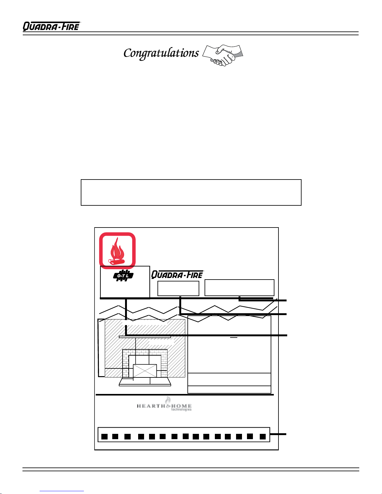
SAMPLE OF SERIAL NUMBER / SAFETY LABEL
LOCATION: On Beaded Chain, Left Side Behind Outer Skin
craftsmanship. Each unit is meticulously fabricated and surfaces
are hand-nished for lasting beauty and enjoyment. Our pledge
to quality is completed as each model undergoes a quality control
inspection. From design, to fabrication, to shipping: Our
guarantee of quality is more than a word, it’s Quadra-Fire
tradition, and we proudly back this tradition with a Limited
Lifetime Warranty.
We wish you and your family many years of enjoyment in the
warmth and comfort of your hearth appliance. Thank you for
choosing Quadra-Fire.
Page 2
435-1320B
Serial Number
Model Name
Test Lab &
Report No.
Manufactured Date
August 20, 2008

BODEGA BAY WOOD INSERT
R
Table of Contents
SAFETY & OVERVIEW OF APPLIANCE
Location & Sample of Serial Number Label ----------- 2
Dimensions ----------------------------------------------------- 4
Minimum Clearances to Combustibles ------------------ 4
Listings ---------------------------------------------------------- 5
Chimney Height & Draft and 2-10-3 Rule -------------- 5
Installation Recommendations ---------------------------- 5
General Installation Procedures -------------------------- 6
Alternate Floor Protection Worksheet ------------------- 6
Chimney Requirements ------------------------------------- 7
Ovalizing Round Stainless Steel Liner ------------------ 7
INSTALLATION OPTIONS
Mobile Home --------------------------------------------------- 8
Masonry Fireplace -------------------------------------------- 9
Metal Heat Circulating Masonry -------------------------- 9
Zero Clearance Factory Built Fireplace ----------------- 10
Canadian Masonry & Heat Circulating ------------------ 11
Leveling Bolts and Sheet Metal Shims ------------------ 11
Securing Liner to Chimney Ring -------------------------- 12
PARTS & ACCESSORY INSTALLATION
Outside Air Installation -------------------------------------- 12
Panel and Trim Set ------------------------------------------- 13
Door Handle Assembly -------------------------------------- 13
Door Latch Adjustment -------------------------------------- 13
Blower Cord Installation ------------------------------------ 14
Fan (Blower) Assembly Replacement ------------------- 14
Zero Clearance Adjustable Trim Support --------------- 15
OPERATION OVERVIEW
Wood Selection & Storing ---------------------------------- 16
Overring-------------------------------------------------------- 16
Building A Fire ------------------------------------------------- 16
Operating Tips ------------------------------------------------- 17
Burn Rates & Opacity ---------------------------------------- 17
Fan Operation Instructions --------------------------------- 17
Ash Removal --------------------------------------------------- 17
Air Quality ------------------------------------------------------- 18
Air Controls, Primary & Start-up -------------------------- 18
MAINTENANCE
Plated Surfaces ----------------------------------------------- 19
Glass Cleaning & Replacement --------------------------- 19
Creosote Formation & Removal -------------------------- 19
Chimney --------------------------------------------------------- 19
Brick Replacement ------------------------------------------- 20
Bafe Removaland Installation ---------------------------- 20
Exploded View ------------------------------------------------- 21
PARTS & ACCESSORIES LIST -------------------------- 22
Service & Maintenance Log -------------------------------- 23-24
Homeowner’s Notes ----------------------------------------- 25
Warranty Policy ------------------------------------------------ 26-27
Contact Information ------------------------------------------ 28
August 20, 2008
435-1320B
Page 3
BODEGA BAY WOOD INSERT
R
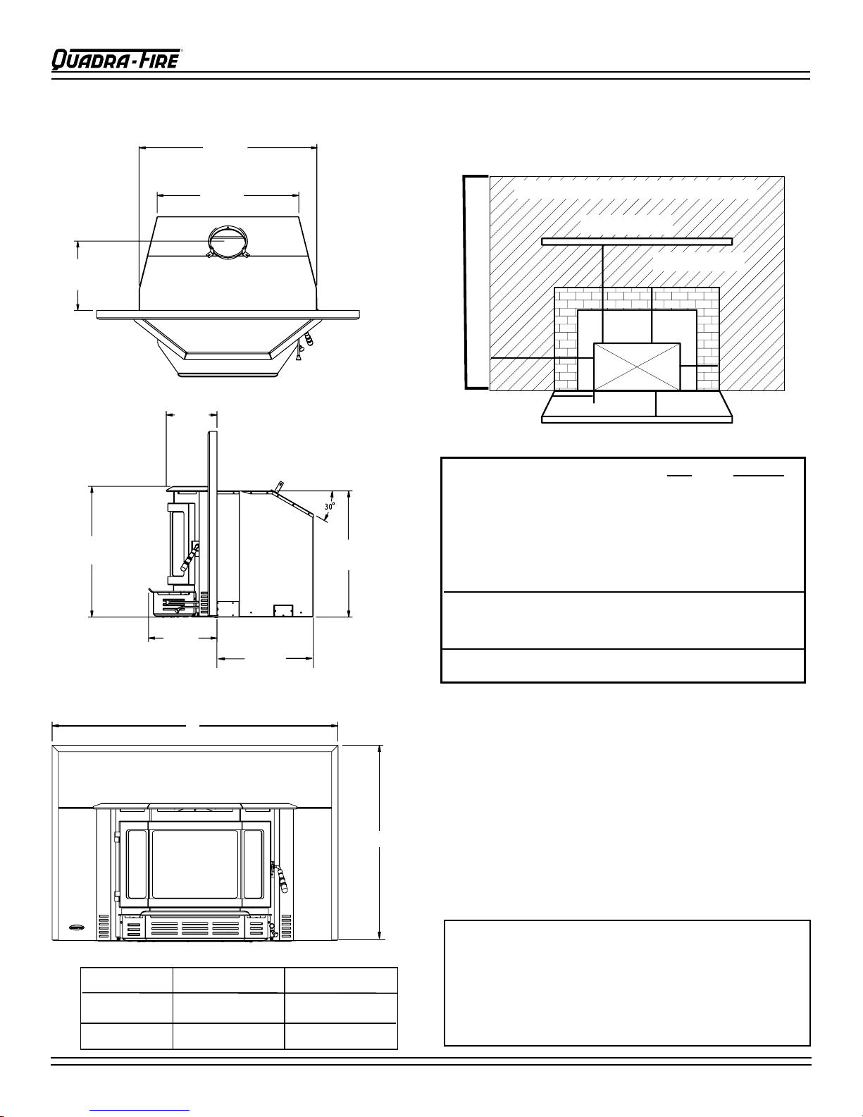
Hearth Extension
A
B
C
D
F
E
Insert
SideWall
Maximum Mantel Depth - 10" (254mm)
Fascia or Trim
Mantel
Thermal Protection USA & Canada
USA CANADA
A Sidewall to Stove 15" (381mm) 15" (381mm)
B Mantel to Stove 26" (660mm) 23" (584mm)
C Top Trim to Stove 20" (508mm) 20" (508mm)
D Side Trim to Stove 6" (152mm) 6" (152mm)
E Hearth Extension from Glass 16" (406mm) 18" (457mm)
F
Hearth Extension from Side of Insert
8" (203mm) 8" (203mm)
Thermal protection must be 1/2 Inch (12.7mm) minimum
thickness ('k" value = 0.84) or equivalent material*
*Zero Clearance Installations USA Only
30-3/16"
(767mm)
11-3/4"
(298mm)
24-1/16"
(611mm)
C
L
8-3/8"
(213mm)
21-9/16"
(548mm)
20-13/16"
(529mm)
11-5/16"
(287mm)
16-1/4"
(413mm)
A
B
TOP VIEW
SIDE VIEW
DIMENSIONS
CLEARANCES TO COMBUSTIBLES
United States and Canada
FRONT VIEW
Panel Size
Small
Large
Page 4
A
44-5/8” (1133mm) 30-1/2” (775mm)
50-1/2” (1283mm) 34” (867mm)
B
*See Alternative Floor Protection Worksheet on page 6.
In Canada a full length six inches (152mm) S635 ue liner
required as per ULC S628.
NOTE: When installling into a masonry replace, the replace must be built to UBC Chapter 37 standards. Do not
remove brick or mortar from masonry replace to accomodate insert. The permanent metal warning plate provided
must be attached to the back of the replace stating the replace may have been altered to accomodate the insert and
must be returned to original condition for use as a conventional replace.
SERIAL NUMBER LABEL LOCATION:
435-1320B
ON BEADED CHAIN, LEFT SIDE
BEHIND OUTER SKIN
August 20, 2008

BODEGA BAY WOOD INSERT
R
3 ft Min
(91cm)
2 ft Min (61cm)
10 ft Min
(305cm)
2-10-3 RULE
LINER CONNECTOR
FLUE
GAS
DIRECTION
CRIMPED
END
TOWARDS
STOVE
LISTINGS
These installation instructions describe the installation and
operation of the Quadra-Fire Bodega Bay Wood Insert. This
insert meets the U.S. Environmental Protection Agency’s 1990
particulate emission standards. This product is listed by OMNI-Test
Laboratories, Inc. to UL Safety Standard 1482, and ULC S628, and
(UM) 84-HUD. It is approved for mobile home installations when
not installed in a sleeping room and when an outside combustion
air inlet is provided. The structural integrity of the mobile home
oor, ceiling, and walls must be maintained. The insert must be
properly grounded to the frame of the mobile home.
Check with your local building code agency before you begin your
installation to ensure compliance with local codes, including the
need for permits and follow-up inspections. Be sure local building
codes do not supersede UL specications and always obtain a
building permit so that insurance protection benets cannot be
unexpectedly cancelled. If any assistance is required during
installation, please contact your local dealer.
CHIMNEY HEIGHT/DRAFT
To be sure that your Quadra-Fire insert burns properly, the chimney
draft (static pressure) should be approximately -0.10” water column
(W.C.) during a high burn and -0.04” W.C. during a low burn,
measured 6” (152mm) above the top of the insert after one hour of
operation at each burn setting.
NOTE: These are guidelines only, and may vary somewhat for
individual installations.
The insert was designed for and tested on a six inch (152mm)
chimney, 12-14 ft (360-420cm) high, measured from the base
of the insert. The further your stack height or diameter varies
from this conguration, the possibility of performance problems
increases. In addition, exterior conditions such as roof line,
surrounding trees, prevailing winds and nearby hills can inuence
insert’s performance.
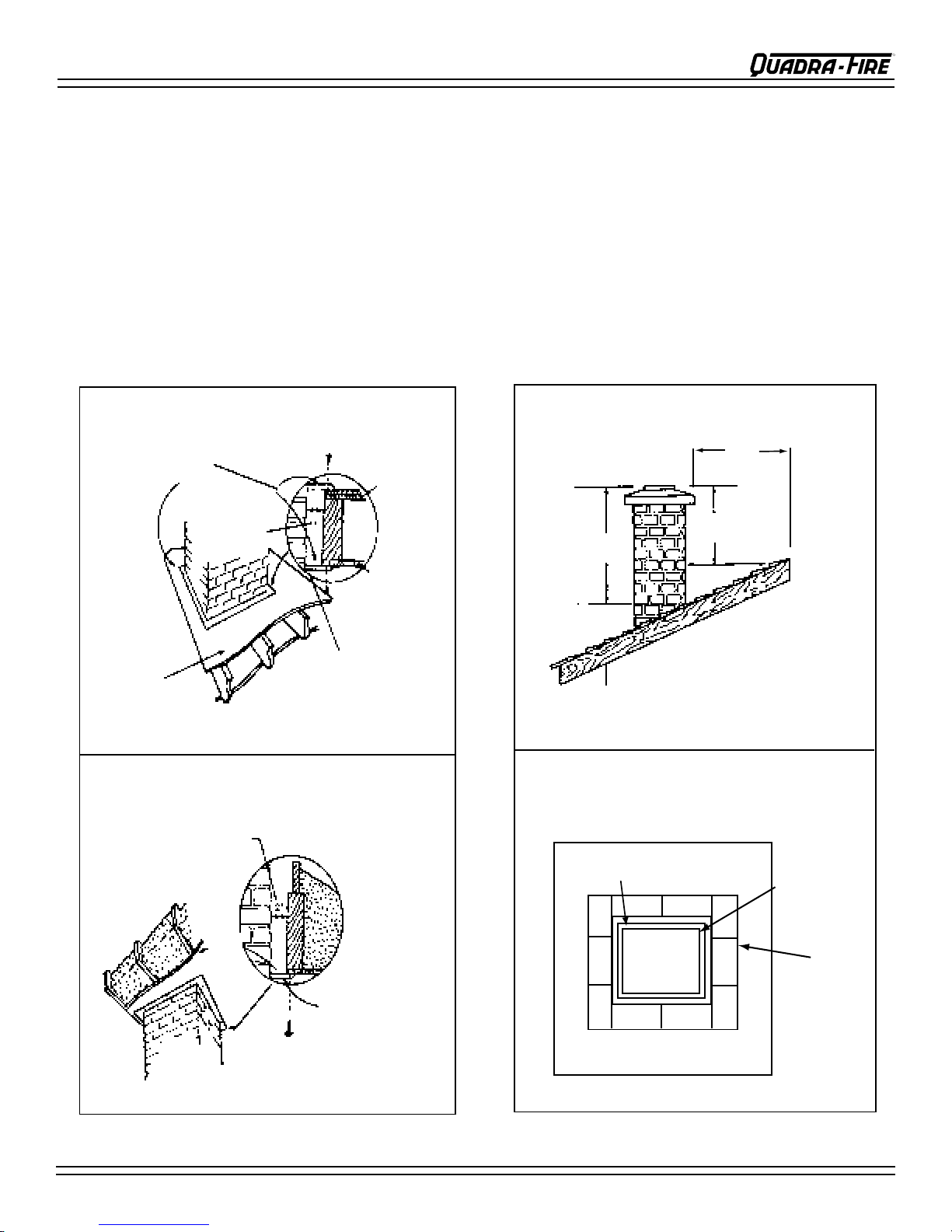
A masonry chimney or a listed factory-built UL103 HT Class “A”
chimney must be the required height above the roof and any other
nearby obstructions. The chimney must be at least 3 ft (91cm)
higher than the highest point where it passes through the roof and at
least 2 ft (61cm) higher than the highest part of the roof or structure
that is within 10 ft (305cm) of the chimney, measured horizontally.
See 2-10-3 Rule (Figure 5A). These are safety requirements
and are not meant to assure proper ue draft.
CHIMNEY HEIGHT/DRAFT (CONT’D)
AVOID FIRE: T
material does not contact the chimney, a chimney inside the house
must have at least 2 inches (51mm) of air space clearance around
the chimney. A chimney outside the house must have at least 1 inch
(25mm) clearance to the combus
stops must be installed at the spaces where the chimney passes
through oors and/or ceilings. Refer to Figures 7A & 7B on page
7. Canadian installations require a full reline of the chimney
NOTE: Clearances may only be reduced by means approved by
the regulatory authority having jurisdiction.
WE RECOMMEND that a qualied building inspector and your
insurance company representative review your plans before
installation.
o ensure that insulation or any other combustible
tible structure. Noncombustible re
INSTALLATION RECOMMENDATIONS
This product has met and surpassed the most stringent emissions
standards in the United States. The sophistication of the interior
rebox design requires that a proper draft be supplied by the chimney, therefore adherence to the following factors will enable your
insert to operate at its optimum capability.
REQUIRED: A minimum starter pipe reaching to the base of the
existing code approved masonry chimney and an airtight face seal,
but a full chimney liner for factory-built replaces is recommended
for USA and is required in Canada.
BETTER: Direct connection to the rst ue liner in accordance with
the requirements of the NFPA 211.
BEST: A complete relining of the chimney system with a 6 inch
(152mm) diameter listed, stainless liner. Required for factory-built
replace installations in Canada, recommended in USA. The sections
must be attached to the insert and to each other with the crimped
(male) end pointing toward the insert. See Figure 5B. All joints,
including the connection at the ue collar, should be secured with
three sheet metal screws. Make sure to follow the minimum clearances to combustibles as set out on page 4 of the manual.
Figure 5A
August 20, 2008
435-1320B
Figure 5B
Page 5
BODEGA BAY WOOD INSERT
R
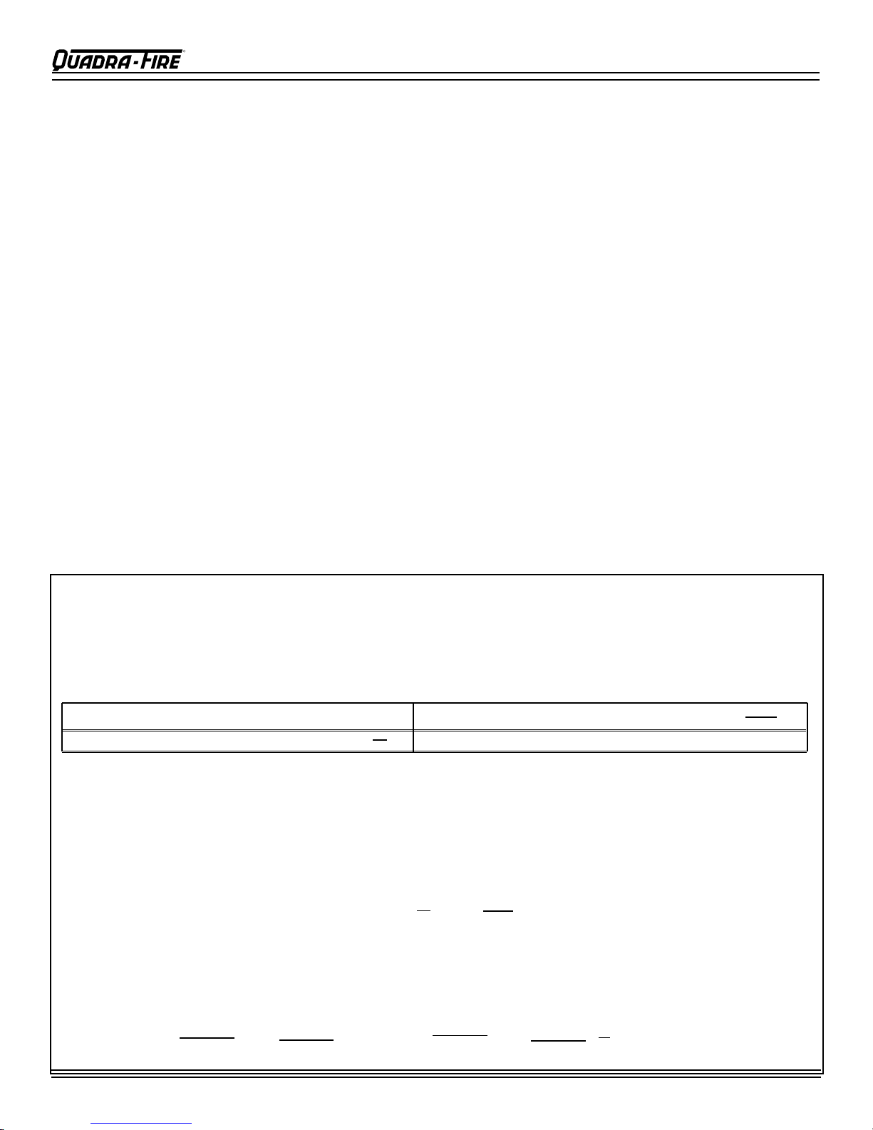
=
1
R =
x T
1
x 0.75 = 0.893
k
.84
4" brick of R = 0.2, therefore:
1/8" mineral board of k = 0.29, therefore:
(ft2)(hr)(oF)
Btu
R =
Btu(in)
ft2(hr)(oF)
= K x 12
k =
1
k
r =
(ft2)(hr)(oF)
(Btu)(in)
=
K =
Btu(ft)
ft2(hr)(oF)
R =
x T
1
k
R =
x T
1
K x 12
GENERAL INSTALLATION PROCEDURE
• DO NOT CONNECT THIS UNIT TO A CHIMNEY FLUE SERVING ANOTHER APPLIANCE.
• Install liner, if required, for your chosen installation.
• Attach metal warning plate to the back of the replace with screws or nails.
•
Set appliance on the hearth (See Hearth Requirements page 4 and Support Kit information on page 15.)
• Complete the vent connection required for your installation type.
• Relocate plate for Outside Air. (Required for Mobile Home Installation) page 12; Assemble Panel & Trim Set and
install as one piece. See page 13.
•
Position unit into replace leaving width enough for berglass batting to be inserted around face seal.
•
Work unit securely into the replace using sheet metal shims if leveling bolts are needed. See Figure 11B on page 11.
• Remove all labels from glass prior to building rst re.
• Ensure that plated surfaces are cleaned prior to building rst re. See page 19.
• Read Operation Instructions found on pages 17 and 18.
IF INSTALLING THIS MODEL TO A MASONRY CHIMNEY, ALWAYS BE SURE THE CHIMNEY IS IN GOOD CONDITION AND
THAT IT MEETS THE MINIMUM STANDARDS OF THE NATIONAL FIRE PROTECTION ASSOCIATION (NFPA) STANDARD 211.
A FACTORY BUILT CHIMNEY MUST BE 6 INCH (152mm) UL 103 HT AND ULC S629.
THIS APPLIANCE IS MADE WITH A 6 INCH (152mm) DIAMETER CHIMNEY CONNECTOR AS THE FLUE COLLAR ON THE
UNIT. CHANGING THE DIAMETER OF THE CHIMNEY CAN AFFECT DRAFT AND CAUSE POOR PERFORMANCE. IT IS NOT
RECOMMENDED TO USE OFFSETS OR ELBOWS AT ALTITUDES ABOVE 4000 FEET ABOVE SEA LEVEL OR WHEN THERE
ARE OTHER FACTORS THAT AFFECT FLUE DRAFT.T SEE PAGE 5.
CAUTION: THIS APPLIANCE IS HOT WHILE IN OPERATION AND MAY REMAIN SO UP TO 40 MINUTES AFTER THERE
IS NO FUEL IN THE FIREBOX. IF THIS APPLIANCE IS IN A HIGH TRAFFIC AREA OR CHILDREN MAY BE NEAR, IT IS
RECOMMENDED THAT YOU PURCHASE A DECORATIVE BARRIOR TO GO IN FRONT OF THE APPLIANCE.
ALTERNATE FLOOR PROTECTION WORKSHEET
How to determine if alternate oor protection materials are acceptable:
All oor protection must be non-combustible (i.e., metals, brick, stone, mineral ber boards, etc.). Any organic materials (i.e., plastics, wood paper
products, etc.) are combustible and must not be used. The oor protection specied includes some form of thermal designation such as R-value
(thermal resistance) or k-factor (thermal conductivity).
PROCEDURE:
1. Convert specication to R-value:
R-value given - no conversion needed.
k-factor is given with a required thickness (T) in inches:
2. Determine the R-value of the proposed alternate oor protector.
i. Use the formula in step (1) to convert values not expressed as “R”.
ii. For multiple layers, add R-values of each layer to determine overall R-value.
3. If the overall R-value of the system is greater than the R-value of the specied oor protector, the alternate is acceptable.
EXAMPLE: The specied oor protector should be 3/4 inch thick material with a k-factor of 0.84. The proposed alternate is 4” brick with an R-factor of 0.2
over 1/8” mineral board with a k-factor of 0.29.
Step (a): Use formula above to convert specication to R-value.
Step (b): Calculate R of proposed system.
K-factor is given with a required thickness (T) in inches:
r-factor is given with a required thickness (T) in inches: R =
Step (c): Compare proposed system R
Page 6
of 1.231 to specied R of 0.893. Since proposed system R
total
435-1320B
is greater than required, the system is acceptable.
total
August 20, 2008
BODEGA BAY WOOD INSERT
R
Floor
Ceiling
Caulk
Floor
(second Story)
Non-Combustible
Firestopping
Material
Minimum 1 inch (25mm)
clearance from exterior
chimney to sheathing
Firestopping
2 inch
(51mm)
Non-combustible
fire stopping material
Minimum 2 inch (51mm) clearance
from combustible material
and insulation
ceiling
At least 2 ft
(61cm)
At least 3 ft
(91cm)
10 ft
(305cm)
CHIMNEY TOP VIEW
FLUE
Foundation
1/2" (12.7mm) airspace
5/8" (16mm)
Fireclay Flue
Liner
Chimney Wall
4" (102mm)
Nominal
CHIMNEY REQUIREMENTS
A chimney must be the required height above the roof
or other obstruction for safety and for proper draft operation. The requirement is that the chimney must be at
least 3 ft (91cm) higher than the highest point where it
passes through the roof, and at least 2 ft (61cm) higher
than the highest part of the roof or structure that is
within10 ft (305cm) of the chimney, measured horizontally. Refer to Figure 7C.
Figure 7A
OVALIZING ROUND STAINLESS STEEL
LINERS
Ovalizing round stainless steel liners to acommodate
the liner passing through the damper region of a replace is an allowable and acceptable practice.
Ensure that the ovalization is minimized to the extent
required to t through the damper.
Figure 7C
Figure 7B
August 20, 2008
435-1320B
Figure 7D
Page 7
BODEGA BAY WOOD INSERT
R
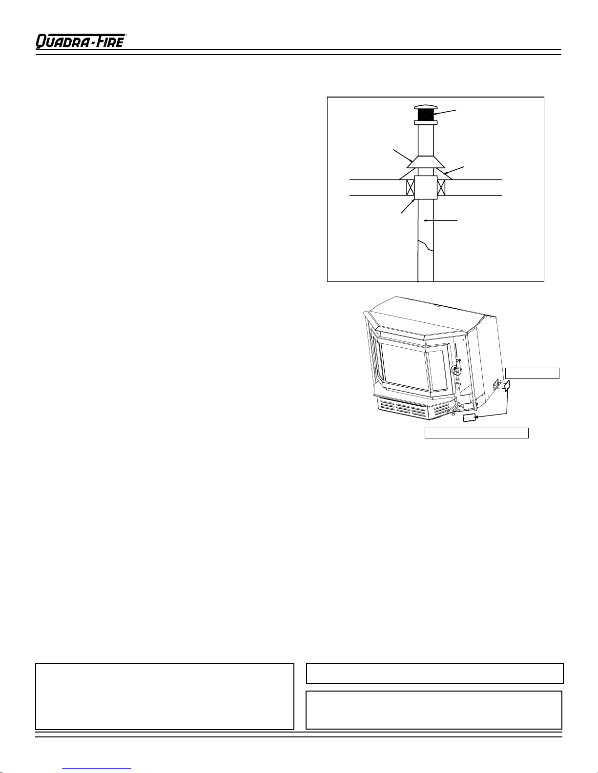
Spark Arestor Cap
Roof Flashing
Storm Collar
Joist Shield/Firestop
Double Wall
Connector Pipe
2. Reinstall using same screws
1. Remove Plate
INSTALLATIONS INTO ZERO CLEARANCE FIREPLACES IN MOBILE HOMES
(IN USA ONLY)
1. An outside air inlet must be provided for combustion and
must remain clear of leaves, debris, ice and/or snow. It
must be unrestricted while unit is in use to prevent room air
starvation which can cause smoke spillage and an inability
to maintain a re. Smoke spillage can also set off smoke
alarms.
2. Unit must be secured to the mobile home structure.
Remove bolts from each side of insert and use plumbers
tape to secure to structure (a washer may be required).
Reinstall bolts.
3. Unit must be grounded with #8 solid copper grounding
wire or equivalent and terminated at each end with N.E.C.
approved grounding device.
4. The factory -bui lt fire plac e must meet (UM)84-HUD
requirements for outside combustion air supply to the
replace re chamber and the chimney must be listed to
UL103-HT or a listed UL-1777 full length 6 inch (152mm)
diameter liner must be used. It must be equipped with a
spark arrestor cap and the outside air must be installed on
the insert. (See Figure 8A and installation instructions
of page 12.)
5. Refer to page 4 of this manual or the Serial Number/Safety
Label for clearances to combustibles. The label is located
on the left side behind outer skin on a beaded chain
6. Floor protection requirements on page 4 must be followed
precisely.
7. Use silicone to create an effective vapor barrier at the location were the chimney or other component penetrates
Figure 8A - Installing Outside Air
to the exterior of the structure.
8. Follow the chimney and chimney connector manufacturer’s instructions when installing the ue system for use
in a mobile home.
NOTE: Offsets from the vertical, not exceeding 45°, are allowed per Section 905(a) of the Uniform Mechanical Code
(UMC). Offsets greater than 45° are considered horizontal and are also allowed, providing the horizontal run does
not exceed 75% of the vertical height of the vent. Construction, clearance and termination must be in compliance
with the UMC Table 9C. This installation must also complies with NFPA 211.
NOTE: Top sections of chimney must be removable to allow maximum clearance of 13.5 tft (405cm) from ground
level for transportation purposes.
9. Burn wood only. Other types of fuels may generate poisonous gases (e.g., carbon monoxide).
CAUTION:
THE STRUCTURAL INTEGRITY OF THE MOBILE HOME
FLOOR, WALL AND CEILING/ROOF MUST BE MAINTAINED.
(i.e., DO NOT CUT THROUGH FLOOR JOIST, WALL STUD,
CEILING TRUSS, ETC.)
WARNING: DO NOT INSTALL IN SLEEPING ROOM.
WARNING: NEVER DRAW COMBUSTION AIR FROM A WALL,
FLOOR OR CEILING CAVITY OR FROM ANY ENCLOSED
SPACE SUCH AS AN ATTIC OR GARAGE.
Page 8
435-1320B
August 20, 2008
 Loading...