

Page 1
O- T L
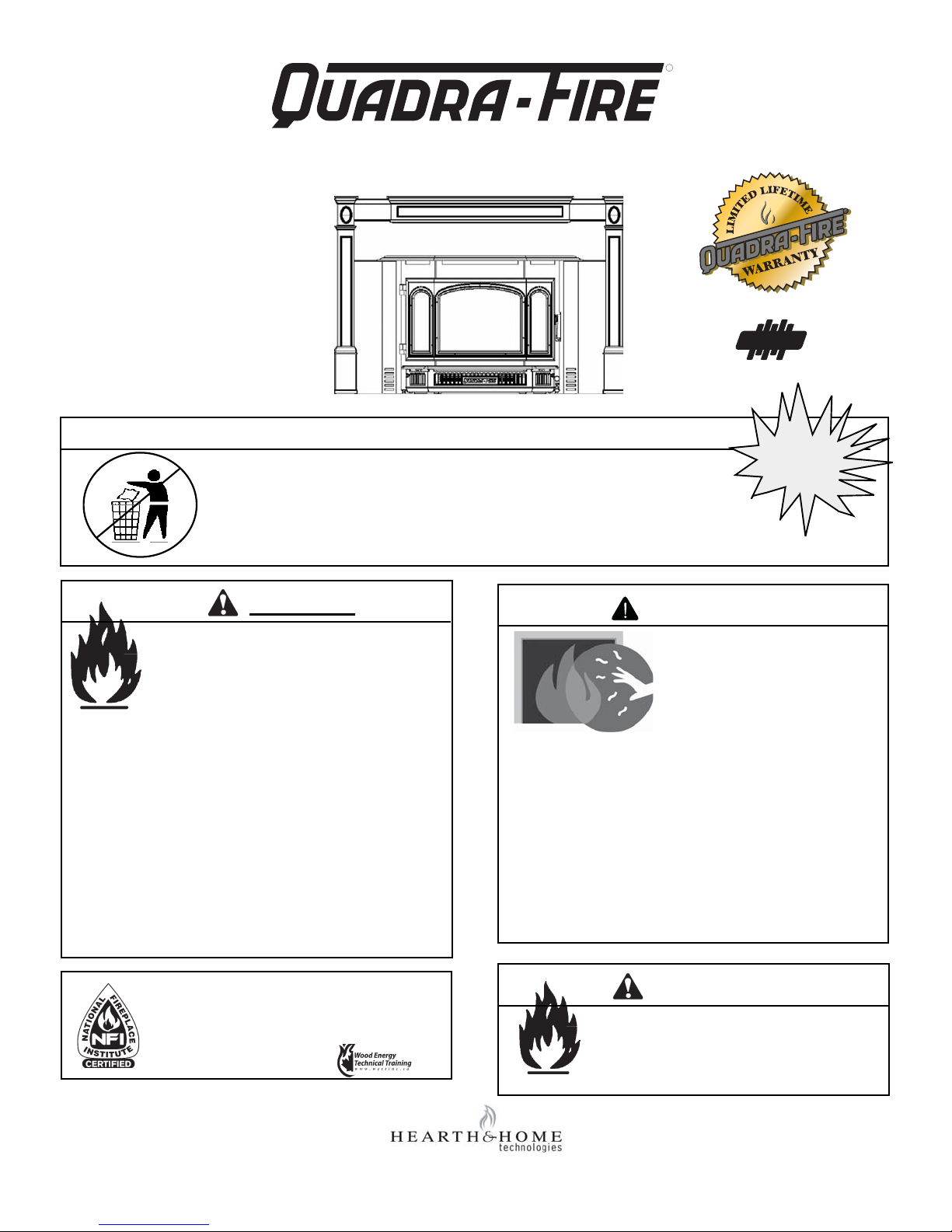
Models:
4100I-GD-B
R
4100- I ACT WOOD INSERT
Advanced Combustion Technology (ACT)
4100I-NL-B
DO NOT DISCARD THIS MANUAL
•
Important operating
and maintenance
instructions included.
WARNING
If the information in these
instructions is not followed
exactly, a fi re may result causing
property damage, personal injury,
or death.
• Do not store or use gasoline or other
fl ammable vapors and liquids in the
vicinity of this or any other appliance.
• Do not overfi re - If heater or chimney
connector glows, you are overfi ring.
Overfi ring will void your warranty.
• Comply with all minimum clearances to
combustibles as specifi ed. Failure to
comply may cause house fi re.
• Read, understand and
follow these instructions
for safe installation and
operation.
NOTICE
US
DO NOT
DISCARD
Beaverton
Oregon USA
Tested and
Listed by
OMNI-Test Laboratories, Inc.
• Leave this manual with
party responsible for
use and operation.
O-T
C
WARNING
HOT SURFACES!
GLASS AND OTHER
SURFACES ARE HOT
DURING OPERATION AND
COOL DOWN.
Hot glass will cause burns.
• Do not touch glass until it is cooled
• NEVER allow children to touch glass
• Keep children away
• CAREFULLY SUPERVISE children in the same room
as appliance
• Alert children and adults to hazards of high
temperatures
High temperatures may ignite clothing or other
fl ammable materials.
• Keep clothing, furniture, draperies and other
combustibles away.
Installation and service of this appliance should
be performed by qualifi ed personnel. Hearth &
Home Technologies recommends NFI certifi ed
professionals, or technicians supervised by an
NFI certifi ed professional.
1445 North Highway
Colville, WA 99114-2008
250-7201D March 27, 2008
WARNING
Fire Risk.
For use with solid wood fuel only.
Other fuels may overfi re and generate
poisonous gases (i.e. carbon monoxide).
www.quadrafi re.com
Page 2
R
y
4100-I
INSERT
O- T L
SAMPLE
4100-I ACT WOOD INSERT
and Welcome to the Quadra-Fire Famil
Hearth & Home Technologies welcomes you to our tradition
of excellence! In choosing a Quadra-Fire appliance, you
have our assurance of commitment to quality , durability , and
performance.
This commitment begins with our research of the market,
including ‘Voice of the Customer’ contacts, ensuring we
make products that will satisfy your needs. Our Research
and Development facility then employs the world’s most
advanced technology to achieve the optimum operation
of our stoves, inserts and fi replaces. And yet we are old-
fashioned when it comes to craftsmanship. Each unit is
With warm regards,
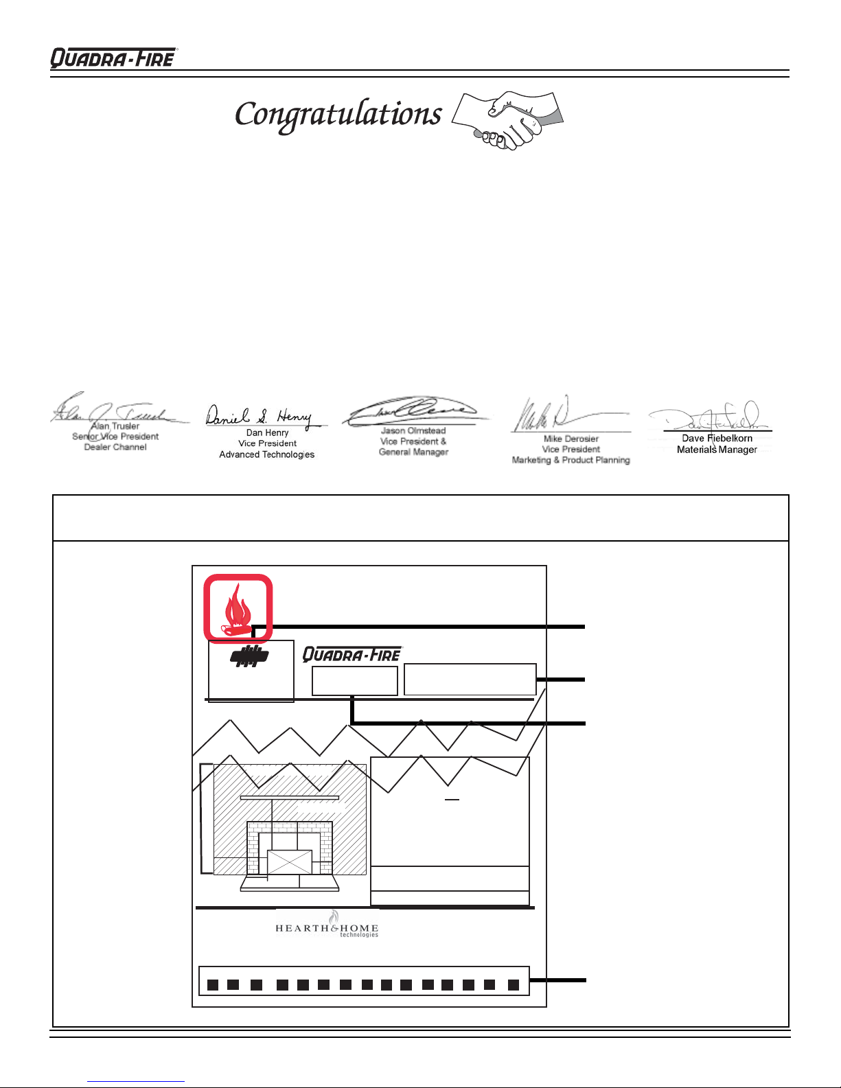
SAMPLE: CLEARANCE TO COMBUSTIBLES LABEL
LOCATION: Back side of left side panel.
!
meticulously fabricated and gold and nickel surfaces are
hand-fi nished for lasting beauty and enjoyment. Our pledge
to quality is completed as each model undergoes a quality
control inspection. From design, to fabrication, to shipping:
Our guarantee of quality is more than a word, it’s QuadraFire tradition, and we proudly back this tradition with a Limited Lifetime Warranty.
We wish you and your family many years of enjoyment in
the warmth and comfort of your hearth appliance. Thank
you for choosing Quadra-Fire.
CAUTION:
HOT WHILE IN OPERATION DO NOT TOUCH,
KEEP CHILDREN AND CLOTHING AWAY.
CONTACT MAY CAUSE SKIN BURNS. KEEP FURNISHINGS AND
OTHER COMBUSTIBLE MATERIAL FAR AWAY FROM THE APPLIANCE.
SEE NAMEPLATE AND INSTRUCTIONS.
Tested and
Listed by
OMNI-Test Laboratories, Inc.
Report #061-S-40-2
UL 1482, ULC S628
LISTED ROOM HEATER, SOLID FUEL TYPE. "For Use with Solid Wood Fuel Only."
Also for use in Mobile Home.
SideWall
A
Manufactured by:
U.S. ENVIRONMENTAL PROTECTION AGENCY - Certified to comply with July 1990 particulate emission standards.
2005 2006 2007 Jan Feb Mar Apr May June July Aug Sept Oct. Nov. Dec.
Beaverton
O-T
Oregon USA
C
TESTED TO:
Maximum Mantel Depth - 10"
Mantel
B
Insert
F
Hearth Extension
1445 N. Highway, Colville, WA 99114
SAMPLE
Model: 4100-I
INSERT
PREVENT HOUSE FIRES
Fascia or Trim
C
D
E
www.quadrafire.com
R
Serial No / Numéro De Série
007
Minimum Clearances To Combustible Material
Masonry, Heat Circulating & Zero Clearance *
Refer to Clearances on reverse side for Canada
USA
A Sidewall to Stove 15"
B Mantel to Stove 26"
C Top Trim to Stove 20"
D Side Trim to Stove 6"
E Hearth Extension from Glass 16"
earth Extenson from Side of Insert
F H
Thermal Protection USA & Canada
1/2 inch (12.7mm) of k=0.84
*Zero Clearance Installations USA Only
DO NOT REMOVE THIS LABEL
Made in U.S.A
8"
.
250-7191
Test Lab & Report No.
Serial Number
Model Name
Manufactured Date
Page 2
250-7201 Rev D
March 27, 2008
Page 3

4100-I ACT WOOD INSERT
Table of Contents
R
SAFETY & OVERVIEW OF APPLIANCE
Dimensions ----------------------------------------------------- 4
Minimum Clearances to Combustibles ------------------ 5
Listings ---------------------------------------------------------- 6
Chimney Height & Draft and 2-10-3 Rule --------------6
Installation Recommendations ----------------------------6
General Installation Procedures --------------------------7
Alternate Floor Protection Worksheet -------------------7
Chimney Requirements ------------------------------------- 8
Ovalizing Round Stainless Steel Liner ------------------8
INSTALLATION OPTIONS
Mobile Home --------------------------------------------------- 9
Masonry Fireplace -------------------------------------------- 10
Metal Heat Circulating Masonry -------------------------- 10
Factory-Built Zero Clearance Fireplace ----------------- 11
Canadian Masonry & Heat Circulating ------------------12
Leveling Bolts and Sheet Metal Shims ------------------ 12
Securing Liner to Chimney Ring -------------------------- 13
PARTS & ACCESSORY INSTALLATION
MAINTENANCE
Gold/Nickel Plated Surfaces ------------------------------- 20
Glass Cleaning & Replacement --------------------------- 20
Creosote Formation & Removal -------------------------- 20
Chimney --------------------------------------------------------- 20
Brick Replacement -------------------------------------------21
Baffl e Removal ------------------------------------------------21
Exploded View ------------------------------------------------- 22
PARTS & ACCESSORIES LIST ---------------------23-24
SERVICE & MAINTENANCE LOG -----------------25
WARRANTY POLICY ------------------------------------ 27
CONTACT INFORMATION -----------------------------28
Outside Air Installation --------------------------------------13
Panel Sets and Trim Sets ---------------------------------- 14
Blower Cord Installation ------------------------------------ 15
Blower Control Box with Switch --------------------------- 15
Fan (Blower) Replacement -------------------------------- 15
Zero Clearance Adjustable Trim Support --------------- 16
Door Handle Assembly -------------------------------------- 16
Door Latch Adjustment -------------------------------------- 16
OPERATION OVERVIEW
Wood Selection & Storing ----------------------------------17
Overfi ring ------------------------------------------------------- 17
Building A Fire -------------------------------------------------17
Operating Tips ------------------------------------------------- 18
Burn Rates & Opacity ---------------------------------------18
Fan Operation Instructions --------------------------------- 18
Ash Removal --------------------------------------------------18
Burning Process ---------------------------------------------- 19
Air Controls, Primary & Start-up -------------------------- 19
March 27, 2008
250-7201 Rev D
Page 3
Page 4
R
(610mm)
4100-I ACT WOOD INSERT
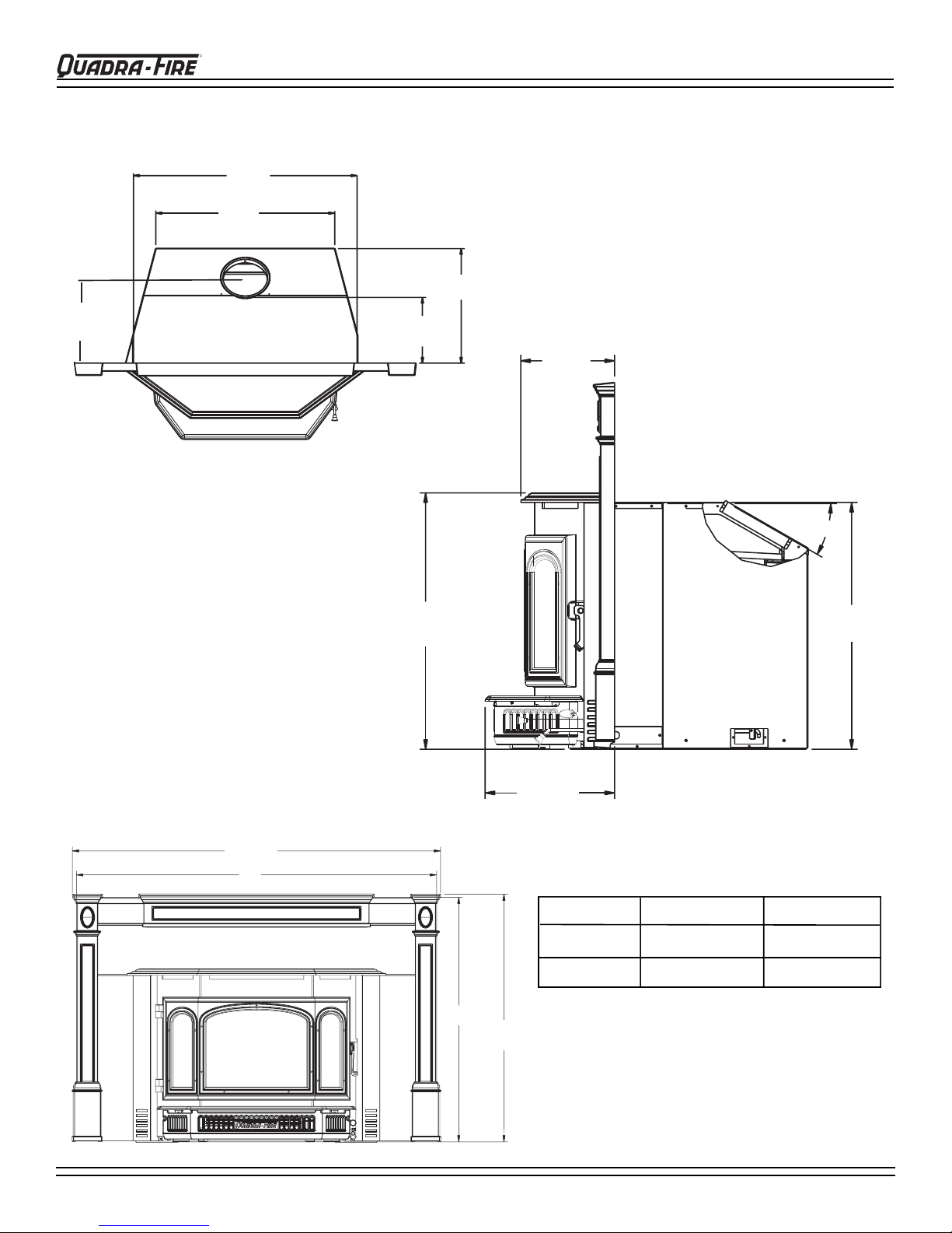
DIMENSIONS
30"
(762mm)
24"
12-1/8"
(308mm)
C
L
TOP VIEW
16-1/4"
(413mm)
9-5/16"
(135mm)
21-5/8"
(549mm)
7-7/8"
(200mm)
SIDE VIEW
o
30
20-7/8"
(530mm)
FRONT VIEW
45-3/4"
(1162mm)
A
Page 4
10-7/8"
(276mm)
B
30-7/8"
(784mm)
250-7201 Rev D
Panel Size
Standard
Large
A
B
44-3/4” (1137mm) 30-1/2” (775mm)
48” (1219mm) 34” (867mm)
March 27, 2008
Page 5
4100-I ACT WOOD INSERT
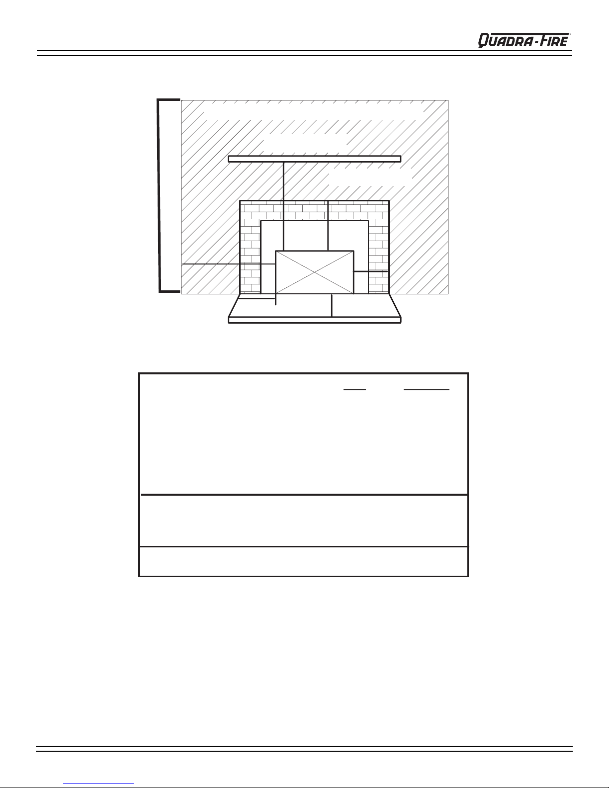
CLEARANCES TO COMBUSTIBLES
United States and Canada
Maximum Mantel Depth - 10" (254mm)
Mantel
R
B
Fascia or Trim
SideWall
C
A
Insert
F
Hearth Extension
Omni Report #061-S-40-2
USA CANADA
A Sidewall to Stove
B Mantel to Stove 26" (660mm) 23" (584mm)
C Top Trim to Stove 20" (508mm) 20" (508mm)
D Side Trim to Stove 6" (152mm) 6" (152mm)
E Hearth Extension from Glass 16" (406mm) 18" (457mm)
F
Hearth Extension from Side of Insert
E
15" (381mm) 15" (381mm)
8" (203mm) 8" (203mm)
D
Thermal protection must be 1/2 Inch (12.7mm) minimum
thickness ('k" value = 0.84) or equivalent material*
*See Alternative Floor Protection Worksheet on page 7.
In Canada a full length six inch (152mm) S635 fl ue liner
required as per ULC S628.
March 27, 2008
Thermal Protection USA & Canada
*Zero Clearance Installations USA Only
NOTE: When installing into a masonry fi replace, the fi re-
place must be built to UBC Chapter 37 standards. Do not
remove brick or mortar from masonry fi replace to accom-
modate insert. The permanent metal warning plate provided
must be attached to the back of the fi replace stating the fi re-
place may have been altered to accommodate the insert and
must be returned to original condition for use as a conventional fi replace.
250-7201 Rev D
Page 5
Page 6
R
4100-I ACT WOOD INSERT
LISTINGS CHIMNEY HEIGHT/DRAFT (CONT’D)
These installation instructions describe the installation and
operation of the Quadra-Fire 4100-I Wood Insert. This insert
meets the U.S. Environmental Protection Agency’s 1990
particulate emission standards. This product is listed by
OMNI-Test Laboratories, Inc. to UL Safety Standard 1482,
and ULC S628, and (UM) 84-HUD. This insert is approved
for mobile home installations when not installed in a sleeping
room and when an outside combustion air inlet is provided.
The structural integrity of the mobile home fl oor, ceiling,
and walls must be maintained. The insert must be properly
grounded to the frame of the mobile home.
Check with your local building code agency before you begin
your installation to ensure compliance with local codes,
including the need for permits and follow-up inspections.
Be sure local building codes do not supersede UL specifi ca-
tions and always obtain a building permit so that insurance
protection benefi ts cannot be unexpectedly cancelled. If
any assistance is required during installation, please contact
your local dealer.
CHIMNEY HEIGHT/DRAFT
To be sure that your Quadra-Fire insert burns properly, the
chimney draft (static pressure) should be approximately
-0.10” water column (W.C.) during a high burn and -0.04”
W.C. during a low burn, measured six inches (152mm) above
the top of the insert after one hour of operation at each burn
setting.
NOTE: These are guidelines only, and may vary somewhat
for individual installations.
The insert was designed for and tested on a six inch (152mm)
chimney, 12 ft-14 ft (360-420cm) high, measured from the
base of the insert. The further your stack height or diameter
varies from this confi guration, the possibility of performance
problems increases. In addition, exterior conditions such as
roof line, surrounding trees, prevailing winds and nearby hills
can infl uence insert’s performance.
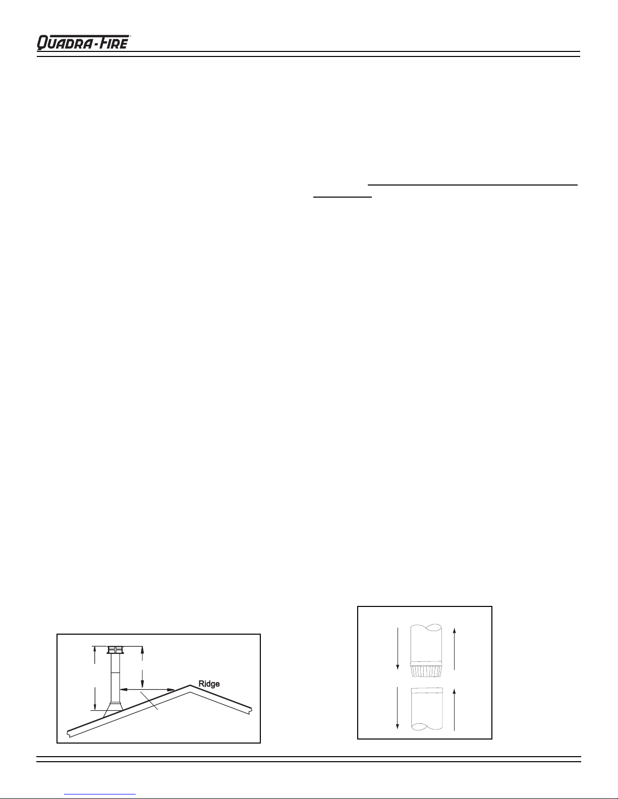
A masonry chimney or a listed factory-built UL103 HT Class
“A” chimney must be the required height above the roof
and any other nearby obstructions. The chimney must be
at least 3 ft (91cm) higher than the highest point where it
passes through the roof and at least 2 ft (61cm) higher than
the highest part of the roof or structure that is within 10 ft
(305cm) of the chimney , measured horizontally. See 2-10-3
Rule (Figure 6A). These are safety requirements and are
not meant to assure proper fl ue draft.
2-10-3 RULE
AVOID FIRE: To ensure that insulation or any other combustible material does not contact the chimney, a chimney
inside the house must have at least 2 inches (51mm) of air
t
space clearance around
the house must have at least one
he chimney. A chimney outside
inch (25mm) clearance
to the combustible structure. Noncombustible fi re stops
must be installed at the spaces where the chimney passes
through fl oors and/or ceilings. Refer to Figures 8A & 8B
on page 8. Canadian installations require a full reline of
the chimney
NOTE: Clearances may only be reduced by means approved
by the regulatory authority having jurisdiction.
WE RECOMMEND that a qualifi ed building inspector and
your insurance company representative review your plans
before and after installation.
INSTALLATION RECOMMENDATIONS
This product has met and surpassed the most stringent emissions
standards in the United States. The sophistication of the interior
fi rebox design requires that a proper draft be supplied by the chimney, therefore adherence to the following factors will enable your
insert to operate at its optimum capability.
REQUIRED: A minimum NFPA 211 required stainless steel
liner connector pipe extending to the fi rst fl ue liner of the
existing code approved masonry chimney . To eliminate dilution air in the chimney , seal the damper area of the chimney
around the chimney connector.
BEST: A complete relining of the chimney system with a six
inch (152mm) diameter listed, stainless steel liner. The liner
must be connected to the insert fl ue collar and extend the
entire height of the chimney , terminating slightly above a plate
that seals the top of the chimney. All joints should be secured
with 3 sheet metal screws. The sections must be attached to
the insert and to each other with the crimped (male) end pointing toward the insert. Figure 6B.
Minimum clearances to combustibles must be maintained.
A full reline is required for factory-built fi replace installations in
Canada and is highly recommended in USA.
LINER CONNECTOR
3 ft Min
(91cm)
2 ft Min (61cm)
10 ft Min
(305cm)
Figure 6A
Page 6
250-7201 Rev D
CRIMPED
END
TOWARDS
STOVE
Figure 6B
FLUE
GAS
DIRECTION
March 27, 2008
Page 7

4100-I ACT WOOD INSERT
R
GENERAL INSTALLATION PROCEDURE
• DO NOT CONNECT THIS UNIT TO A CHIMNEY
FLUE SERVING ANOTHER APPLIANCE.
• Install liner, if required, for your chosen installation.
• Attach metal warning plate to the back of the fi replace
with screws or nails.
•
Set appliance on the hearth (See Hearth Requirements
page 5 and Support Kit information on page 16.
• Complete the vent connection required for your installation type.
• Relocate plate for Outside Air. (Required for Mobile
Home Installation) page 13; Assemble Panel Set
and Cast Trim Set or the Basic Panel & Trim Set and
install as one piece. See page 14.
•
Position unit into fi replace leaving width enough for fi ber-
glass batting to be inserted around face seal.
•
Work unit securely into the fi replace using sheet metal
shims if leveling bolts are needed. See Figure 12B on
page 12.
• Remove all labels from glass prior to building fi rst fi re.
• Ensure that plated surfaces are cleaned prior to building fi rst fi re. See page 20.
• Read Operation Instructions found on pages 18 and
19.
IF INST ALLING THIS MODEL TO A MASONRY CHIMNEY,
ALW A YS BE SURE THE CHIMNEY IS IN GOOD CONDITION
AND THA T IT MEETS THE MINIMUM ST ANDARDS OF THE
NATIONAL FIRE PROTECTION ASSOCIATION (NFPA)
ST ANDARD 21 1. A FACTOR Y BUILT CHIMNEY MUST BE
6 INCH (152mm) UL103 HT AND ULC S629.
THIS APPLIANCE IS MADE WITH A 6 INCH (152mm) DIAMETER CHIMNEY CONNECTOR AS THE FLUE COLLAR ON
THE UNIT . CHANGING THE DIAMETER OF THE CHIMNEY
CAN AFFECT DRAFT AND CAUSE POOR PERFORMANCE. IT IS NOT RECOMMENDED TO USE OFFSETS
OR ELBOWS AT ALTITUDES ABOVE 4000 FEET ABOVE
SEA LEVEL OR WHEN THERE ARE OTHER FACTORS
THAT AFFECT FLUE DRAFT. SEE PAGE 5.
)
CALCULA TING ALTERNATE FLOOR
PROTECTION MATERIAL
Thermal Conductivity: k value
The k value indicates the amount of heat (in BTU’s) that will fl ow
in 1 hour through 1 square foot of a uniform material 1 inch thick
for each degree (F) of temperature difference from one side of
the material to the other. The LOWER the k factor means less
heat is being conducted through the non-combustible material to
the combustible material beneath it. The k value of a material
must be equal or smaller then the required k value to be acceptable.
(BTU) (inch)
(foot2 (hour) (oF)
Thermal Resistance: R value
The R value is a measure of a material’s resisteance to heat
transfer. R value is convenient when more than one material is
used since you can add the R values together, whereas you can
not do this for k value. The HIGHER the R factor means less
heat is being conducted through the non-combustible material to
the combustible material beneath it. The R value of a material
must be equal or larger then the required R value to be acceptable.
Converting k to R:
Divide 1 by k and multiply the results times the thickness in inches of the material.
R = 1/k x inches of thickness
Converting R to k:
Divide the inches of thickness by R.
k = inches of thickness/R
Calculations:
Example: Floor protection requires k value of 0.84 and 3/4 inch
thick.
Alternative material has a k value of 0.6 and is 3/4 inch thick.
Divide 0.6 by .75 = k value of 0.80. This k value is smaller than
0.84 and therefore is acceptable.
CAUTION: THIS APPLIANCE IS HOT WHILE IN OPERATION AND MAY REMAIN SO UP TO 40 MINUTES OR
LONGER AFTER THERE IS NO FUEL IN THE FIREBOX.
IF THIS APPLIANCE IS IN A HIGH TRAFFIC AREA OR
CHILDREN MAY BE NEAR, IT IS RECOMMENDED THAT
YOU PURCHASE A DECORATIVE BARRIER TO GO IN
FRONT OF THE APPLIANCE.
March 27, 2008
250-7201 Rev D
Page 7
Page 8
R
4100-I ACT WOOD INSERT
CHIMNEY REQUIREMENTS
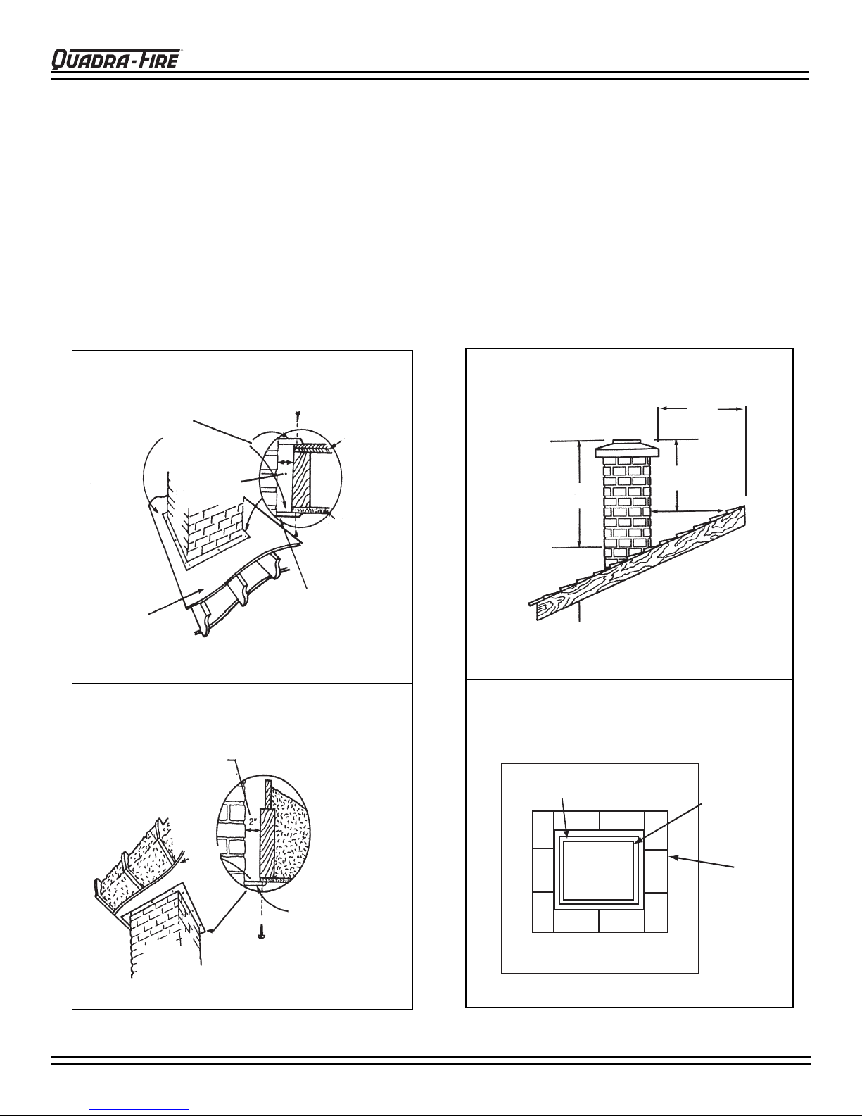
A chimney must be the required height above the roof
or other obstruction for safety and for proper draft operation. The requirement is that the chimney must be at
least 3 feet (91cm) higher than the highest point where
it passes through the roof, and at least 2 feet (61cm)
higher than the highest part of the roof or structure that
is within10 feet (305cm) of the chimney , measured horizontally. Refer to Figure 8C.
Figure 8A
Non-Combustible
Firestopping
Material
2 inch
(51mm)
Firestopping
Floor
Ceiling
OVALIZING ROUND STAINLESS STEEL
LINERS
Ovalizing round stainless steel liners to accommodate
the liner passing through the damper region of a fi re-
place is an allowable and acceptable practice.
Ensure that the ovalization is minimized to the extent
required to fi t through the damper.
Figure 8C
CHIMNEY HEIGHT
At least 3 ft
(91cm)
10 ft
(305cm)
At least 2 ft
(61cm)
Floor
(second Story)
Figure 8B
Caulk
Minimum 1 inch (25mm)
clearance from exterior
chimney to sheathing
Minimum 2 inch (51mm) clearance
from combustible material
and insulation
ceiling
Non-combustible
fire stopping material
Figure 8D
CHIMNEY TOP VIEW
1/2" (12.7mm) airspace
FLUE
Foundation
5/8" (16mm)
Fireclay Flue
Liner
Chimney Wall
4" (102mm)
Nominal
Page 8
250-7201 Rev D
March 27, 2008
Page 9
4100-I ACT WOOD INSERT
INSTALLATIONS INTO ZERO CLEARANCE
FIREPLACES IN MOBILE HOMES
(IN USA ONLY)
R
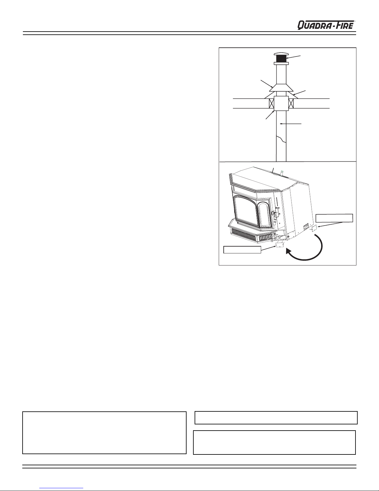
Spark Arestor Cap
1. An outside air inlet must be provided for combustion and must
remain clear of leaves, debris, ice and/or snow. It must be
unrestricted while unit is in use to prevent room air starvation
which can cause smoke spillage and an inability to maintain a
fi re. Smoke spillage can also set off smoke alarms.
2. Unit must be secured to the mobile home structure. Remove
bolts from each side of insert and use plumbers tape to secure
to structure (a washer may be required). Re-install bolts.
3. Unit must be grounded with #8 solid copper grounding wire or
equivalent and terminated at each end with N.E.C. approved
grounding device.
4. The factory-built fi replace must meet (UM)84-HUD requirements
for outside combustion air supply to the fi replace fi re chamber
and the chimney must be listed to UL03 HT or a listed UL-1777
full length six inch (152mm) diameter liner must be used. It must
be equipped with a spark arrestor cap and the outside air must
be installed on the insert. (See Figure 9A and installation
instructions of page 13.)
5. Refer to page 5 of this manual or the serial number/safety label
for clearances to combustibles. The label is located on a beaded
chain on the left side behind outer skin.
Storm Collar
Joist Shield/Firestop
2. Re-install plate
Roof Flashing
Double Wall
Connector Pipe
1. Remove plate
6. Floor protections requirements on page 5 must be followed
precisely.
Figure 9A - Installing Outside Air
7. Use silicone to create an effective vapor barrier at the location were the chimney or other component penetrates to the
exterior of the structure.
8. Follow the chimney and chimney connector manufacturer’s instructions when installing the fl ue system for use in a
mobile home.
NOTE: Offsets from the vertical, not exceeding 45°, are allowed per Section 905(a) of the Uniform Mechanical Code
(UMC). Offsets greater than 45° are considered horizontal and are also allowed, providing the horizontal run does
not exceed 75% of the vertical height of the vent. Construction, clearance and termination must be in compliance
with the UMC Table 9C. This installation must also complies with NFPA 211.
NOTE: Top sections of chimney must be removable to allow maximum clearance of 13.5 ft. (405cm) from ground level for
transportation purposes.
9. Burn wood only. Other types of fuels may generate poisonous gases (e.g., carbon monoxide).
CAUTION:
THE STRUCTURAL INTEGRITY OF THE MOBILE HOME
FLOOR, WALL AND CEILING/ROOF MUST BE MAINTAINED.
(i.e., DO NOT CUT THROUGH FLOOR JOIST, WALL STUD,
CEILING TRUSS, ETC.)
WARNING: DO NOT INSTALL IN SLEEPING ROOM.
WARNING: NEVER DRA W COMBUSTION AIR FROM A W ALL,
FLOOR OR CEILING CAVITY OR FROM ANY ENCLOSED
SP ACE SUCH AS AN A TTIC OR GARAGE.
March 27, 2008
250-7201 Rev D
Page 9
Page 10

R
4100-I ACT WOOD INSERT
INSTALLATION OPTIONS
Refer to: Clearances to Combustibles on page 5, Canadian Installation requirements on page 12,
Hearth Requirements on page 5 and Zero Clearance Adjustable Support Kit on page 16.
MASONRY FIREPLACE
USING DIRECT-CONNECT METHOD
This product conforms with the UL Standard for Safety
1482 (USA) and ULC S628 (Canada) in all respects, and
is approved to UL & ULC safety standards for installation
and use within a fi replace with a masonry chimney in accor-
dance with NFP A 211, with or without a direct fl ue collar con-
nection. A starter pipe is required to reach to the bottom of
the existing fl ue.
1. Secure the fi replace damper in the open position. If this
cannot be accomplished, it will be necessary to remove
the damper.
2. Seal either the damper area around the chimney liner
with a high temperature sealant or the fi replace front with
fi berglass batting.
3. The chimney should be examined for cracks, loose
mortar, and other signs of deterioration and blockage.
The insert should not be installed until it is determined
that the chimney is safe for use. Since an oversized fl ue
contributes to the accumulation of creosote, the size of
the fl ue should be checked to determine that it is not too
large for the insert. The chimney should also be checked
to ensure it meets the minimum standard of the National
Fire Protection Association (NFPA) Standard 211. The
following bullets list the more critical requirements for a
properly constructed chimney:
• The masonry wall of the chimney, if brick or modular
block, must be a minimum of 4 inches (102mm) nominal
thickness. A chimney of rubble stone must be at least 12
inches (305mm) thick
• The chimney must have a fi re clay fl ue liner (or equiva-
lent) with a minimum thickness of 5/8” (16mm) and must
be installed with refractory mortar. An equivalent liner
must be a listed chimney liner system or other approved
material.
• Cross-sectional area should be no more than 3 times the
cross-sectional area of the fl ue collar of the insert. (28 sq
inch fl ue area x 3 inches = 84 square inches maximum
chimney area).
•
A chimney inside the house must have at least two inches
(51mm) of clearance to the combustible structure. A chimney outside the house must have at least 1 inch (25mm)
clearance to the combustible structure. Non-combustible
fi re stops must be installed at the spaces where the chimney passes through fl oors and/or ceiling (See Figure 8A
and 8B on page 8).
NOTE: In Canada, a full reline is required.
Masonry Chimney
Flue Tile
Mantel
Air-tight Face Seal
Damper Area
Full Listed
Liner Option
Direct Connect
Seal Option
Minimum Starter
Pipe Option
Figure 10A - Installation Into Masonry Fireplace
METAL HEAT CIRCULATING MASONRY
This product conforms with the safety standard UL1482
(USA) and ULC S628 (Canada) in all respects and is
approved to UL & ULC safety standards for installation and
use within a fi replace with masonry chimney, in accordance
with NFPA 211, with or without a direct fl ue collar connec-
tion. A starter pipe is required into existing chimney.
Mantel
Listed Liner
SEAL DAMPER AREA OR FACE SEAL
Figure 10B - Installation Into Metal Heat Circulating
Showing Use Of Starter Pipe
Page 10
250-7201 Rev D
March 27, 2008
Page 11

4100-I ACT WOOD INSERT
FACTORY-BUILT ZERO CLEARANCE FIREPLACE
(USA INSTALLATIONS ONLY)
The Quadra-Fire 4100-I Insert is listed to UL 1482 Standard and is approved for installation into listed factory-built zero
clearance fi replaces listed to UL 127 conforming to the following specifi cations and instructions:
Minimum Width of cavity opening 30 inches 762mm
Minimum Height 21 inches 533mm
Minimum Depth from front to rear 16-1/4 inches 413mm
The following modifi cations of factory built fi replaces are permissible: 1) removal of damper; 2) removal of smoke shelf
or baffl e; 3) removal of ember catches; 4) removal of fi re grate; 5) removal of viewing screen/curtain; and, 6) removal of
doors.
NOTE: Installation into fi replaces without a permit will void the listing.
The factory built chimney must be listed per UL127 and meet the type HT requirements of UL 103. Factory-built fi replace
chimneys tested to UL127-1998, may be at the fi replace manufacturer’s option, tested to the same criteria as UL 103 HT
requirements. If the chimney is not listed as meeting HT requirements, or if the factory built fi replace was tested prior to
1998, a full height listed chimney liner must be installed from the appliance fl ue collar to the chimney top. The liner must
meet type HT requirements (2100ºF) per UL1777. The liner must be securely attached to the insert fl ue collar and the
chimney top. To prevent room air passage to the chimney cavity of the fi replace, seal either the damper area around the
chimney liner with high temperature sealant or the fi replace front with fi berglass batting.
R
The fi replace must not be altered, except that the damper may be removed to accommodate a direct-connect starter pipe
or chimney liner, and external trim pieces which do not af fect the operation of the fi replace may be removed providing they
can be stored on or within the fi replace for reassembly if the insert is removed. The permanent metal warning label pro-
vided must be attached to the back of the fi replace, with screws or nails, stating that the fi replace may have been altered to
accommodate the insert, and must be returned to original
condition for use as a conventional fi replace.
If the hearth extension is lower than the fi replace opening,
the portion of the insert extending onto the hearth must be
supported. Manufacturer designed adjustable support kit
can be ordered from your dealer. See page 16.
Final approval of this installation type is contingent upon
the authority having jurisdiction.
Mantel
Listed Liner
March 27, 2008
Figure 11A - Installation Into A Factory Built
250-7201 Rev D
SEAL DAMPER AREA OR FACE SEAL
Zero Clearance Fireplace
Page 11
Page 12

R
4100-I ACT WOOD INSERT
INSTALLATION IN CANADA
MASONRY and HEAT-CIRCULATING
(INSTALLATIONS INTO FACTORY-BUILT FIREPLACES ARE PROHIBITED IN CANADA)
Whether installed in a masonry or heat-circulating fi replace, this fi replace insert must be installed with a continuous chim-
ney liner of six inch (152mm) diameter extending from the fi replace insert to the top of the chimney. The chimney liner must
conform to the Class 3 requirements of CAN/ULC-S635, Standard for Lining Systems for Existing Masonry or Factory-Built
Chimneys and Vents, or CAN/ULC-S640, Standard for Lining Systems for New Masonry Chimneys.
• Do not remove bricks or mortar from fi replace to accommodate insert.
• The face of the fi replace must be sealed to prevent room air passage into the chimney cavity.
• The permanent metal warning label provided must be affi xed to the back of the fi replace with screws or nails to
the fi replace, in a location readily visible should the fi replace insert by removed, stating that the fi replace may
have been altered to accommodate the insert, and must be returned to original condition for use as a conventional fi replace.
• Circulating air chambers may not be blocked.
LEVELING BOLTS AND SHEET METAL SHIMS
This product shipped with two leveling bolts, and two sheet
metal guides for ease in sliding the insert into place when
using the leveling bolts. Not all installations will require the
use of the leveling bolts. The sheet metal guides are used
only when the leveling bolts are necessary. Discard if not
needed.
cut-out view
Reach between side of insert and outer skin
Leveling Bolt
Figure 12A
SHEET METAL GUIDES
Slide each guide under the insert on each side placing
them directly under leveling bolts. If they are not directly
under the bolts, the bolts may hang up on uneven material
when sliding the insert into place. See Figure 12B.
ADJUSTING THE LEVELING BOLTS
It is best to use a 1/2 inch (12.7mm) socket wrench with an
extended handle for ease in adjusting bolts to the desired
level. The bolts will adjust from 0 to 2 inches (0 - 51mm).
Y ou can also reach in and adjust the bolts by hand, although
space is limited. Figure 12A.
Sheet Metal Shims
Place under leveling bolts
and slide insert into place
Leveling Bolts
Page 12
250-7201 Rev D
Figure 12B
March 27, 2008
Page 13

4100-I ACT WOOD INSERT
SECURING LINER TO CHIMNEY RING
There are two options to secure the liner to the chimney ring: See Figure 13A.
R
Option One: If there is enough room on the top of the
insert to work, hand bend the two tabs upward 90°.
Secure the liner with the supplied hex head bolts 1/420-3/4.
Option Two: Remove the manifold tubes, fi berboard
baffl e and ceramic blanket. From inside the fi rebox,
pull liner down through the chimney ring below the
outer skin. There are two pre-drilled holes in the chimney ring 180° apart. Secure the liner with the supplied
hex head bolts 1/4-20-3/4.
NOTE: T abs are shipped from factory in a fl at position.
Bend upwards 90 degrees.
OUTSIDE AIR INSTALLATION
IMPORTANT!
2 pre-drilled holes on
chimney ring under outer skin
(access through firebox)
Attach liner with 2 tabs
Figure 13A
THE ZERO CLEARANCE
FIREPLACE OUTSIDE
AIR MUST BE TURNED
1. Remove plate
TO “ON”
2. Re-install plate
Figure 13B
Tools Needed: Phillips Head Screwdriver
1. Remove three screws and cover plate from back side of insert. Save the screws.
2. Re-attach the cover plate using the same screws to front side of the insert as shown in Figure 13B.
3. Repeat same procedure for other side of insert.
NOTE: This insert requires replacement of combustion air. If your home is fairly air-tight, it is recommended that
you install outside air. If you are installing into a Mobile Home, outside air is required. See page 9.
March 27, 2008
250-7201 Rev D
Page 13
Page 14

R
4100-I ACT WOOD INSERT
PANEL SET and CAST TRIM SET
STANDARD SIZE: 30-1/2” h x 44-3/4”w
LARGE SIZE: 34”h x 48”w
Panel and Cast Trim must be ordered separately.
Included in Panel Kit: (2) side panels, left and right; (1) panel top; (2) trim pieces; (1) trim top; (1) fastener package.
Included in Cast Trim Kit: (2) cast trim legs, left and right; (1) cast trim header; (2) cast trim footers, left and right.
Tools Needed: Powered Phillips Head Screw Driver
1. Remove contents from box being careful not to scratch or damage cast trim pieces.
2. Lay the panel set face down on protective covering to prevent scratching the painted surface.
3. Secure panel set together with screws provided. Figure 14A
4.
Now bend the tabs down toward the backside of the panel set, on top piece and on each leg. Leave panel set face down.
5. P
lace the corresponding cast trim pieces (2 cast trim legs and 1 cast trim header) underneath panel set, also face down.
6. Place washer provided over tab and secure the trim and panel together with screw. Continue for all tabs.
7. Secure cast footers with screws.
NOTE: DO NOT PICK UP ASSEMBLED UNIT BY CORNERS. IT IS TOO HEAVY AND MAY DAMAGE THE
PANELS. PICK UP FROM CENTER.
8. Slide assembled panel and trim over top of the insert into place.
9. Secure panels to insert with 8-32 sheet metal screws through tabs on bottom lower inside corners on side panels.
Figure 13B.
2. Bend tabs
1. Screw side panels
to top panel
2. Bend tabs
Tab with screw hole to
secure panel to insert
Secure side panels to insert with screws
3. Install Cast Trim
Header
Figure 14B
COMPLETED VIEW
Figure 14A
PANEL and GOLD TRIM SET
BASIC STANDARD SIZE: 30”h x 40”w
1. Repeat Steps 1 - 3 above.
2. To assemble the trim, attach the 2 side trim pieces to the top trim at each corner using the “L” bracket
included in fasteners package. Figure 14C
3. Slide panel and trim over top of the insert and into position.
View of "L" Bracket
installed
Tab with screw
hole to secure
panel to insert
Screw side
panels to top
panel
Figure 14C
Page 14
250-7201 Rev D
Figure 14D
March 27, 2008
Page 15

4100-I ACT WOOD INSERT
A
R
BLOWER CORD LOCATION & BLOWER
CONTROL BOX WITH SWITCH
This insert comes standard with a blower, installed at the
factory with blower cord on right side of insert (as you face
the unit). The blower cord can also be installed on the left
side. Disconnect the cord from right side. ROUTE WIRES IN
FRONT OF F AN. Re-install on the left side. Do not route cord
behind the cooling fan.
Figure 15A
Snap Disc
Black
Black
White
Cooling Fan
Red
Blower Control
Box with Switch
FAN (BLOWER) REPLACEMENT
Included in Kit: Replacement Blower
Tools Needed:
1. Remove bolts from both sides of the insert and slide the
lower cast cover towards you. See Figure 15D
2. Loosen 4 screws (2 on each side of the motor) that
secures motor to the housing. Remove the motor. See
Figure 15E.
3. Attach new motor using the same screws to the blower
housing.
4. Re-attach lower cast cover to insert using the bolts
removed in Step 1.
Remove Bolt
Figure 15D
5-32 Wrench and Phillips Head Screwdriver.
Remove Bolt
Figure 15B - Right Side Location
Red
Black
Snap Disc
White
Cooling Fan
Figure 15E
Remove 4 screws, lift
motor from housing
Figure 15C - Left Side Location
Operating the Blower Control Box with Switch
1. The blower will turn on/off automatically when set to AUTO.
2. When set to MANUAL, the fan will turn on/off only when you
turn it on or off. This setting over-rides the internal snap
disc.
3. Adjust the speed of the fan by turning the HIGH/LOW knob
to the desired setting.
UTO: Fan will
turn ON/OFF
automatically and
is controlled by the
internal Snap Disc
FAN
HIGH
MANUAL
AUTO
OFF
MANUAL: Over-rides
the internal Snap Disc
LOW
March 27, 2008
250-7201 Rev D
Page 15
Page 16

R
4100-I ACT WOOD INSERT
ZERO CLEARANCE ADJUSTABLE TRIM SUPPORT
Two sizes: 9”d x 45”w and 12”d x 50”w, both 2” to10” Height Adjustment
Included in Kit: (1) Trim Top, (1) Trim Front, (2) Trim Sides, Double-Sided Tape (already installed)
Tools Needed: Phillips Head Screwdriver, Sheet Metal Shears, Measuring Tape, Gloves
1. The 10 screws on each set of scissors will already be loose
when shipped. Figure 16A.
2. Expand scissors to desired height. Tighten screws to hold in
place using Phillips Head screwdriver. Figure 16B.
3. Measure front and side trims to required height to cover scissors and mark pieces for cutting. Cut excess material from
top of trim’s edge, not bottom. This edge will be sharp; wear
gloves to prevent injury to your hands. Figure 16B.
4. Using sheet metal shears, cut trim along the marked edge.
The cut edge fi ts under lip of top trim, so it allows for some
variance in your straight edge.
5. The double-sided tape that holds front and side trims to scissors has a powerful bonding adhesive. Adjustments are
extremely diffi cult once trim has adhered to tape. Do a dry
run fi rst without removing paper from tape.
6. Place cut edge of trim under top lip and into position on scissors. Place side pieces on fi rst and then front piece. The
front piece overlaps side pieces. NOTE: The trim in the Flush
Mount Kit is one piece.
7. Once you are satisfi ed with the positioning, remove trim and
set aside.
8. Remove the paper from double-sided tape that is to accept
trim side. Align side and then press hard against tape to
secure side piece. Repeat for other side. Install front trim
piece last.
NOTE:
3/8” (9.5mm) thick tile or like material can be cut to size and
fi t under lip of top trim edge for a decorative touch. Figure 16C.
DOUBLE-SIDED TAPE
Figure 16A
EXPAND SCISSORS TO DESIRED HEIGHT
INSTALL FRONT TRIM LAST.
Figure 16B
EXPLODED VIEW OF SCISSORS
SCREWS ARE CIRCLED
CORNERS OVERLAP SIDE
TRIM PIECES
DOUBLE-SIDED TAPE
CUT TOP EDGE OF TRIM,
NOT BOTTOM EDGE
Decorative tile
may be installed
DOOR HANDLE ASSEMBLY
Hook Door Latch
Washer
Nut 1/4-20
Washer, 5/8 x 1/4
Door Latch Bracket
Door Handle
Fiber Handle
Figure 16D
DOOR LATCH ADJUSTMENT
It is important the door gasket has a proper seal. As the gasket compresses or
“seats” during use, it may become necessary to adjust or tighten the door latch.
1. Loosen securing screw (do not remove).
2. Turn adjustment bolts as need for adjustment (in or out) using 7/16” end
wrench.
3. Tighten securing screw to hold adjusted position in place.
Page 16
Figure 16C
250-7201 Rev D
Figure 16E
Securing
Screw
Adjustment Bolts
March 27, 2008
Page 17

4100-I ACT WOOD INSERT
OPERATION
WOOD SELECTION AND STORAGE
Burn only dry seasoned wood. Dry, well-seasoned wood will not only minimize the chance of creosote formation but will
give you the most effi cient heat output. Even dry wood contains at least 15% moisture by weight and should be burned hot
enough to keep the chimney hot enough to maintain particulate (smoke) burning. Burning unseasoned wood of any variety
defeats the inserts’ effi ciency.
Dead wood lying on the forest fl oor should be considered wet, and requires full seasoning time. Standing wood can be
considered to be about two-thirds seasoned. Wood is dry enough to burn if the ends of the logs have cracks radiating in all
directions from the center. If your wood sizzles in the fi re, even though the surface is dry, it may not be fully cured.
Drying time can be reduced by splitting wood prior to storage. Since the majority of drying occurs through the cut ends
rather than the sides, stack the wood so both ends of each piece are exposed to air. Store wood under cover, such as in a
shed, or covered with a tarp, plastic, tar paper, sheets of scrap plywood, etc.
OVERFIRING
Do not overfi re. Overfi ring can result in crazing, an effect causing a white, non-removable fi lm to be deposited on the
inside of the glass. Using fl ammable liquids or too much wood, or burning trash in the insert, may result in overfi ring. If
the chimney connector or insert glows red, or worse, white, the insert is overfi red. This condition may ignite creosote in
the chimney, possibly causing a house fi re. If any part of the insert starts to glow, you are in an overfi re situation. If you
overfi re, immediately close the insert controls and door, if open, to reduce the air supply to the fi re. Overfi ring your insert
voids your warranty.
R
BUILDING A FIRE
Before lighting your fi rst fi re in the insert, make certain that the baffl e is correctly positioned. It should be resting against the
rear support. Also refer to care and cleaning of plated surfaces on page 19 before lighting your fi rst fi re.
CAUTION: Never use gasoline, gasoline-type lantern fuel, kerosene, charcoal lighter fl uid, or similar liquids to start
or “freshen up” a fi re in this heater. Keep all such liquids well away from the heater while it is in use.
There are many ways to build a fi re. The basic principle is to light easily-ignitable tinder or paper, which ignites the fast-burn-
ing kindling, which in turn ignites the slow-burning fi rewood. Here is one method that works well:
1. Place several wads of crushed paper on the fi rebox fl oor. Heating fl ue with slightly crumpled newspaper before adding
kindling keeps smoke to a minimum.
2. Lay small dry sticks of kindling on top of the paper.
3. Open Start-Up Air Control (bottom rod) and Primary Air Control (top rod) fully. See Figure 19A on page 19.
4. Ensure that no matches or other combustibles are in the immediate area of the insert, that the room is adequately
ventilated, and the fl ue is unobstructed.
5. Light the paper in the insert. NEVER light or rekindle insert with kerosene, gasoline, or charcoal lighter fl uid; the results
can be fatal.
6. Once the kindling is burning quickly, add several full-length logs three inches (76mm) or four inches (102mm) in diameter .
Be careful not to smother the fi re. Stack the pieces of wood carefully. They should be near enough to keep each other
hot, but far enough away from each other to allow adequate air fl ow between them.
7. When ready to reload the insert, add more logs. Large logs burn slowly, holding a fi re longer. Small logs burn fast and
hot, giving quick heat.
8. Adjust the Start-Up Air Control and Primary Air Control, maintaining fl ames above the fuel. The more you close down
the Primary Control, the lower and slower the fi re will burn. The more you open the Primary Control the more heat will
be produced. The Start-Up Air Control (bottom rod) is only used for the fi rst 5 to 15 minutes.
As long as there are hot coals, repeating steps 7 and 8 will maintain a continuous fi re.
NOTE: Remove all labels from glass front prior to lighting the fi rst fi re.
NOTE: The special high temperature fi nish paint applied to the insert will cure as your insert heats. Y ou will notice
an odor and perhaps see some vapor rise from the insert surface, this is normal. We recommend that you open a
window until the odor dissipates and the paint is cured.
March 27, 2008
250-7201 Rev D
Page 17
Page 18

R
4100-I ACT WOOD INSERT
OPERATING TIPS
HEAT OUTPUT RATES
For maximum operating effi ciency with the lowest emissions, follow these operating procedures:
1. Regardless of desired heat output, when loading insert, burn your Quadra-Fire with both air controls wide open for
a minimum of 5 to 15 minutes.
2. Regulate burn rate (heat output) by using the Primary Control (top rod). The Start-Up Air Control (bottom rod) is
used for initial start-up and reloading.
3. Heat output settings: Follow burn rate instructions listed below.
4. Burn only dry, well-seasoned wood.
BTU / Hr
Below 10,000
10,000 - 15,000
15,000 - 30,000
Maximum Heat
Start-Up Air Control
Closed after 5 to 15 minutes
Closed after 5 to 15 minutes
Closed after 5 to 15 minutes
Closed after 5 to 15 minutes
Primary Control
Pull to Stop
1” - 1-1/4” open
1-1/4” - 2-1/2” open
Fully open
WARNING: Do not operate with Start-Up
Air Control in the open position in excess
of 15 minutes! Risk of extreme temperatures! Prolonged operation of this
unit with the Start-Up Air Control in the
open position may cause the combustible materials around the stove to exceed
safe temperature limits.
*NOTE:
These are approximate settings, and will vary with type of wood or chimney draft. Due to altitude and other environmental
circumstances, this operational information is a guideline only. Similar burn rates may be obtained using other settings unique to
your situation.
BURN RATES
ST ARTING FIRE: Open both controls (push in) completely. After a wood load has been burning on high for 5 to 15 minutes
or longer for very large pieces, close the Start-Up Air Control (bottom rod) by pulling it out.
HIGH: Leave the Primary Air Control fully open (top rod). It is especially important to fully open both controls when reload-
ing the insert as failure to do so could result in excessive emissions, also referred to as ‘opacity’.
After a wood load has been burning on high for 5 to 15 minutes on High to achieve the following burn rates set the
controls as listed below:
MEDIUM HIGH: Close the Primary Air Control to 1-1/4” to 2-1/2” (32mm to 64mm) open. Start-Up Air is closed.
MEDIUM LOW: Close the Primary Air Control to 1” to 1-1/4” (25mm to 32mm) open. Start-Up Air is closed.
LOW: Gradually close down the Primary Air Control by pulling out making sure to maintain fl ames in the insert. (Start-Up
Air is closed). It is very important to maintain fl ames in your insert during the fi rst few hours of a low burn to avoid exces-
sive air pollution.
OPACITY
Opacity is the measure of how clean your insert is burning and is measured in percentages. An opacity of 100% in the
smoke column from a chimney will totally obscure an object. Whereas 0% opacity means that no smoke column can be
seen. A periodic check of the opacity emitted from your chimney will enable you to burn your insert as smoke free as possible.
1. Initial (cold) startup: Leave fan off until your insert is hot and a good coal bed is established, approximately 30 minutes
after fuel is lit.
2. High Burn Setting: The fan may be left on throughout the burn.
3. Medium Low or Medium High Burn Setting: The fan should be left off until a good burn is established, then turned
on a medium or high rate.
4. Low Burn Setting: The fan tends to cool the insert. Leave fan off until the burn is well established; then, if you wish,
turn the fan on at a low rate.
5. The fan is equipped with a rheostat (speed control) with a snap disc. The blower will turn on/off automatically when the
speed control is set to AUTO. When set to MANUAL, the fan will turn on/off only when you turn it on or off. This setting
overrides the snap disc. Adjust the speed of the fan by turning the HIGH/LOW knob to the desired setting.
FAN OPERATING INSTRUCTIONS
Remove cold ashes (not hot) from the insert at regular intervals, depending on your usage. Ashes should be placed in a
metal container with a tight fi tting lid. The closed container of ashes should be placed on a non-combustible fl oor or on the
ground, well away from all combustible materials, pending fi nal disposal. If the ashes are disposed of by burial in soil or
otherwise locally dispersed, they should be retained in the closed container until all cinders have thoroughly cooled. Always
treat ashes as if they contain hot coals.
Page 18
ASH REMOVAL
250-7201 Rev D
March 27, 2008
Page 19

4100-I ACT WOOD INSERT
R
BURNING PROCESS
In recent years there has been an increasing concern about
air quality. Much of the blame for poor air quality has been
placed on the burning of wood for home heating. In order to
improve the situation, we at Quadra-Fire have developed
cleaner-burning wood stoves and inserts that surpass the
requirements for emissions established by our governing
agencies. These appliances must be properly operated in
order to insure that they perform the way they are designed
to perform. Improper operation can turn most any wood stove
or insert into a smoldering environmental hazard.
Kindling or First Stage
It helps to know a little about the actual process of burning
in order to understand what goes on inside a wood burning
appliance. The fi rst stage of burning is called the kindling
stage. In this stage, the wood is heated to a temperature high
enough to evaporate the moisture which is present in all wood.
The wood will reach the boiling point of water (212°F) and will
not get any hotter until the water is evaporated. This process
takes heat from the coals and tends to cool the appliance.
Fire requires three things to burn - fuel, air and heat. So, if
heat is robbed from the appliance during the drying stage, the
new load of wood has reduced the chances for a good clean
burn. For this reason, it is always best to burn dry , seasoned
fi rewood. When the wood isn’t dry, you must open the air
controls and burn at a high burn setting for a longer time to
start it burning. The heat generated from the fi re should be
warming your home and establishing the fl ue draft, not evapo-
rating the moisture out of wet, unseasoned wood, resulting
in wasted heat.
The air control in the right side of the grille, bottom rod, is
called the Start-Up Air Control; it is used during the kindling
stage of burning. It must be closed (pulled out) after the fi rst
5 to 15 minutes.
Final Stage
The fi nal stage of burning is the charcoal stage. This occurs
when the fl ammable gases have been mostly burned and
only charcoal remains. This is a naturally clean portion of
the burn. The coals burn with hot blue fl ames.
It is very important to reload your appliance while enough
lively hot coals remain in order to provide the amount of heat
needed to dry and rekindle the next load of wood. It is best
to open the air controls for a short while before reloading.
This livens up the coal bed. Open door slowly so that ash or
smoke does not exit appliance through opening. You should
also break up any large chunks and distribute the coals so
that the new wood is laid on hot coals.
Air quality is important to all of us, and if we choose to use
wood to heat our homes we should do so responsibly . To do
this we need to learn to burn our stoves in the cleanest way
possible. Doing this will allow us to continue using our wood
stoves for many years to come.
AIR CONTROLS
Start-up System
The combustion air enters at the rear of the fi rebox through
the rear air tubes. This air supply is controlled by the Start-
up Air Control.
Primary Air System
The primary air enters at the upper front of the fi rebox, near
the top of the glass door. This preheated air supplies the
necessary fresh oxygen to mix with the unburned gases,
helping to create second, third and fourth combustions. This
air is regulated by the Primary Air Control. For more primary
air push control “IN”, for less air pull control “OUT”.
Second Stage
The next stage of burning, the secondary stage, is the period
when the wood gives off fl ammable gases which burn above
the fuel with bright fl ames. During this stage of burning it is
very important that the fl ames be maintained and not allowed
to go out. This will ensure the cleanest possible fi re. If you
are adjusting for a low burn rate, you should close down the
air to the point where you can still maintain some fl ame. If
the fl ames tend to go out, it is set too low for your burning
conditions. The air control, located at the right of the grille,
top rod, is the one used to adjust for burn rates. This is called
the Primary Air Control. Figure 19A.
March 27, 2008
Figure 19A
250-7201 Rev D
Primary Air Control
OPEN - PUSH IN
CLOSE - PULL OUT
Start-Up Air Control
Page 19
Page 20

R
4100-I ACT WOOD INSERT
MAINTENANCE
CARE AND CLEANING OF PLATED SURFACES
IMPORTANT: You must clean all the fi ngerprints and oils from the plated surfaces before fi ring the insert for the fi rst time.
Use warm soapy water and a soft rag, glass cleaner and a paper towel, or vinegar and a paper towel to remove the oils. DO
NOT use abrasive cleaners! If not cleaned properly prior to lighting the fi rst fi re, the oils can cause permanent stains. The
plating will be cured upon fi ring of the insert and oils will no longer affect the fi nish. Subsequently, little maintenance is then
required. Wipe clean as needed with a soft towel.
NOTE: Remove all labels from glass prior to lighting the fi rst fi re.
Quadra-Fire inserts are equipped with super heat resistant ceramic glass which can only be broken by impact or misuse.
Clean glass with any non-abrasive glass cleaner. Abrasive cleaners may scratch and cause glass to crack. Inspect glass
regularly. If you fi nd a crack or break, immediately put the fi re out and return the door to your authorized dealer for replace-
ment of glass before further use. Do not substitute materials for glass replacement.
CARE AND CLEANING OF GLASS
WARNING! DO NOT SLAM INSERT DOOR OR
IMPACT THE GLASS WHEN CLOSING THE DOOR,
MAKE SURE THAT LOGS DO NOT PROTRUDE
AGAINST THE GLASS.
WARNING! DO NOT OPERATE WITH BROKEN
GLASS.
WARNING! DO NOT CLEAN GLASS WHEN HOT.
GLASS REPLACEMENT INSTRUCTIONS
Replace with 5mm ceramic glass only
1. Remove door from insert and lay on a padded fl at surface.
2. Remove glass retainer screws using a Phillips screwdriver.
3. Lift glass out of the door frame and/or side frames.
4. Lay new glass with fi berglass tape around it into door frame and/or side frames.
5. Place glass retainers over the fi berglass tape on the edges of the glass and re-install screws. Be sure glass
is centered in the opening (i.e. same space top and bottom, left and right).
6. Tighten screws enough to hold frame and glass in place.
7. Check again for centering of glass in door and/or side frames and give all screws a fi nal tightening.
CREOSOTE FORMATION AND NEED FOR REMOVAL
When wood is burned slowly it produces tar and other organic vapors which combine with expelled moisture, and, in turn
forms creosote. These creosote vapors condense in the relatively cool chimney fl ue when a fi re is newly started, or from a
slowly burning fi re, and accumulate on the fl ue lining of the chimney.
A build up of creosote can then be ignited by sparks rising up the chimney. When ignited, this situation makes an extremely
hot fi re which may damage the chimney and even destroy your home. The chimney connector and chimney should be
inspected at least once every two months during the heating season to determine if a creosote buildup has occurred. It is
extremely important that this residue is removed at regular intervals, usually once a year depending on your burning habits,
to prevent the occurrence of a chimney fi re. It is highly recommended that you contact a professional chimney cleaner for
this area of maintenance.
CHIMNEY
If your type of installation involves a full reline of the chimney , it will be necessary to either remove the baffl e from the insert,
or remove the insert from the fi replace and disconnect the vent prior to cleaning the chimney. Refer to page 20 in this
manual for instructions on Baffl e Removal.
If your type of installation is direct connect within a masonry chimney , the insert will need to be pulled out from the fi replace
and disconnected from the fl ue prior to cleaning the chimney. The creosote can either be caught in a large garbage bag
secured to the pipe or swept and vacuumed out of the fi replace. Reconnect the pipe and re-install the insert following
installation instructions in this manual on page 9.
Page 20
250-7201 Rev D
March 27, 2008
Page 21

4100-I ACT WOOD INSERT
BRICK REPLACEMENT INSTRUCTIONS
The fi rebox is lined with high quality fi rebrick which has excep-
tional insulating properties. There is no need for a grate,
simply build a fi re on the fi rebox of your insert.
1. Be certain coals are completely cold. Remove all old
brick and ash from unit and vacuum out fi rebox.
2. Remove new brick set from box and lay out to THE
diagram as shown.
3. Lay bottom bricks in unit.
4. Install rear bricks on the top of the bottom bricks. Slide
top of bricks under clip on back of fi rebox wall and push
bottom of brick back.
5. Install side bricks. Slide top of brick under clips on side
of fi rebox and push the bottom of the brick until it is fl ush
with the side of the unit.
Item Brick Size Qty in Set
1 9 x 4-1/2 x 1-1/4” with hole 2
2 9 x 4 x 1-1/4” with cut 2
3 4-1/2 x 3 x 1-1/4” 1
4 9 x 4-1/2 x 1-1/4” 12
5 9 x 3 x 1-1/4” 3
6 9 x 1-1/2 x 1-1/4” 2
1
4
6
5
4
4
4
4
2
1
4
5
4
3
4
4
2
Use Part #832-0550 when ordering indi-
6
4
6-1/8"
vidual brick and provide brick dimension
or copy this page and mark the desired
brick and take it to your authorized
dealer.
R
5
4
4
2
2-1/4"
BAFFLE REMOVAL & INSTALLATION
NOTE: The baffl e material is 2700° Fiber Board. Removing hardware exposed to combustion processes can be frustrating. If
your reason for removing the baffl e is simply to clean the chimney, you have alternatives which will save time and ef fort. Call
a qualifi ed chimney sweep or an authorized Quadra-Fire dealer for details.
1. Remove all ash from fi rebox, and extinguish all hot embers before disposal into a metal container.
2. Remove ceramic blanket from above the baffl e.
3. With a 3/16” Allen wrench, remove 2 front manifold tube retainer bolts on the air channel under the end of the front tubes. NOTE:
Soak the bolts with penetrating oil for at least 15 minutes before trying to remove them. Figure 21A.
4. To remove manifold tubes, slide the tube to one side until one end is out of its hole. Then, while lifting that end of the fi ber board
baffl e, pull tube up over the air channel and out of hole at the other end. It is necessary to remove the fi rst two tubes in order to
remove the baffl e. NOTE: When replacing the manifold tubes, be sure the tube with the larger holes is placed in the front for
your insert to operate properly.
5. Slide fi ber board baffl e forward to front of stove and straight out through door. Figure 21B.
6. To install the fi ber board baffl e, repeat steps 2 through 4 in reverse. Be sure the fi ber board baffl e and ceramic blanket are
pushed back fully into position and the ceramic blanket lays fl at.
First tube has larger holes
Ceramic Blanket
Baffle
Allen wrench
on retainer bolt
Figure 21A - Manifold tubes retaining bolt.
March 27, 2008
Figure 21B - Baffl e & Ceramic Blanket on top.
250-7201 Rev D
Page 21
Page 22

R
4100-I ACT WOOD INSERT
EXPLODED VIEWS
15
18
20
17
19
16
10
11
14
13
9
12
8
1
Figure 22C
Item Description Item Description Item Description
1 Ashcatcher 8 Baffl e, Fiberboard 15 Flue T ab
2 Blower, 180 cfm 9 Ceramic Blanket, 1/2” 16 Top, Cast
3 Blower Mount Base 10 Door Latch Box Assembly 17 Brick (2) with holes
4 Blower Housing, Cast 11 Snap Disc 110 degree 18 Brick, Set
5 Blower Mount Clamp 12 Knob, Air Control 19 Wire Access Panel
6 Wire Harness 13 Blower Control Box w/Switch 20 Door Assy w/Glass
7 Manifold Tubes Set 14 Outside Air Cover Plate
2
3
5
6
4
7
21-1/2"
10.0"
5.0"
R5"
14.0"
Ceramic Blanket
Page 22
250-7201 Rev D
March 27, 2008
Page 23

4100-I ACT WOOD INSERT
Service Parts and Accessories
IMPORTANT: THIS IS DATED INFORMATION. The most current information is located on the Quadra-Fire web site at www.
quadrafi re.com. When ordering, supply serial and model numbers to ensure correct part.
R
Item
#
1 Ashcatcher 435-0310
8 Baffl e, Fiberboard 832-3520
9 Blanket, Ceramic 1/2” thick 832-3390
3 Blower Mount Base 435-0320
5 Blower Mount Clamp 435-0400
2 Blower Assembly, 180 cfm 832-3491
13 Blower Control Box with Switch (included wire harness) SRV7000-194
4 Blower Housing, Cast 435-0590
18 Brick Set 832-3500
Brick, Single (give dimensions of brick, see page 21) 832-0550
17 Brick, with holes (Set of 2) SRV435-0800
Brick, Uncut Set of 6 832-3040
Component Pack (includes Owner’s Manual, Touch-up Paint, Warranty Card, Door Handle, 2 Screws, Permanent Label “If Fireplace
Altered”).
19 Door Assembly with Glass, Gold 435-5190
19 Door Assembly with Glass, Nickel 435-5300
19 Door Assembly with Glass, Gold 435-5340
19 Door Assembly with Glass, Nickel 435-5390
22 Door Handle, Fiber SRV433-1380
21 Door Frame, Cast 435-0050
Door Handle Assembly 832-3570
Door Handle Assembly
Door Handle Assembly
Latch Replacement Kit SRV435-5510
Door Handle Arm (Metal) 435-1470
30 Door Latch Arm 435-0250
24 Hook, Door Latch 435-1190
23 Door Latch Bracket 435-1480
29 Door Latch Bracket 435-1370
10 Door Latch Box Assembly 435-5270
27 Glass Frame, Front 435-0960
25 Glass Frame, Side 435-0950
28 Glass Assembly, Front 435-5470
29 Glass Assembly, Side (1 piece) 435-5480
30 Hinge Pin, Gold 72171
30 Hinge Pin, Nickel 433-1590
12 Knob, Air Control 32284
7 Manifold Tubes, Set of 4 832-3530
Manifold Clips & Screws 832-0661
14 Outside Air Cover Plate 435-0290
19 Panel, Wire Access 435-0900
11 Snap Disc, 110 degrees 230-1220
Part Description
Alphabetical Order
SKU
435-5310
March 27, 2008
250-7201 Rev D
Page 23
Page 24

R
4100-I ACT WOOD INSERT
Item
#
Part Description
Alphabetical Order
16 Top, Cast 435-0300
Trim, Cast, Footer, Left 414-7090MBK
Trim, Cast, Footer, Right 414-7100MBK
Trim, Cast, Header 414-7110MBK
Trim, Cast, Leg, Left 414-7120MBK
Trim, Cast, Leg, Right 414-7130MBK
Trim, Cast, Set, Matte Black (5 piece) 811-0930
20 Trim, Ring, Front, Gold 435-0570
20 Trim, Ring, Front, Nickel 435-0990
31 Trim, Ring, Side, Gold 435-0580
31 Trim, Ring, Side, Nickel 435-1000
6 Wire Harness Only 435-1420
29
27
28
25
SKU
24
30
23
31
21
20
22
Figure 24A
Accessories Part No.
Cast Trim Set, Matte Black, 5 pc 811-0930
Panel Set Standard, 30-1/2” h x 44-3/4” w (order cast trim separately) 831-2010
Panel Set, Large, 34” h x 48” w, (order cast trim separately) 831-2020
Panel & Trim Set, Gold, Basic, Standard, 30-1/2” h x 44-3/4” w SP-BB3044-GD
Panel & Trim Set, Nickel, Small, 30-1/2” h x 44-5/8” w SP-BB3044-NL
Zero Clearance Trim Support, Adjustable, 9” d x 45” w, 2” - 10” high 841-0990
Zero Clearance Trim Support, Adjustable, 12” d x 50” w, 2” - 10” high ADJSPT-12
Page 24
250-7201 Rev D
March 27, 2008
Page 25

4100-I ACT WOOD INSERT
Service and Maintenance Log
Date of Service Performed By Description of Service
R
March 27, 2008
250-7201 Rev D
Page 25
Page 26

R
4100-I ACT WOOD INSERT
Consumer’s Notes
Page 26
250-7201 Rev D
March 27, 2008
Page 27

4100-I ACT WOOD INSERT
Lifetime Warranty
LIMITED LIFETIME WARRANTY
The Hearth & Home Technologies limited Lifetime Warranty guarantees that the following components will work as designed for the lifetime of the stove or Hearth & Home Technologies will repair or replace them. These items include but are not limited to steel and cast
iron components, all gas burners, gas logs, combustion chambers, heat exchanger systems, stainless steel fi rebox components, plating,
doors, glass damaged by thermal breakage, steel baffl e supports, steel and ceramic baffl es and manifold tubes. Labor is for the fi rst fi ve
years.
THREE YEAR WARRANTY
Our pellet fi repots are covered under Hearth & Home Technologies three-year warranty program. Labor is for 3 years.
TWO YEAR WARRANTY
All electrical components such as but not limited to blowers, wiring, vacuum switches, speed controls, control boxes, thermodisc switches,
pilot assembly , gas valves, thermostats and remotes are covered under Hearth & Home Technologies two-year warranty program. Ef fective April, 2005 igniters are also covered under the two year warranty. Labor is for two years.
ONE YEAR WARRANTY
Porcelain and Powder Coat fi nishes are warranted against manufacturer defects for one year. Labor to repair or replace these parts is
covered for one year, reimbursed per our warranty service fee schedule.
R
CONDITIONS
This warranty is non-transferable and is made to the original retail purchaser only provided that the purchase was made through an
authorized dealer of Hearth & Home Technologies. It must be installed and operated at all times in accordance with the Installation and
Operating Instructions furnished with this product, as well as any applicable local and national codes. Any alteration, willful abuse, accident, or misuse of the product shall nullify this warranty.
Labor to repair or replace items covered under the limited Lifetime Warranty will be covered for the fi rst fi ve years per our warranty ser-
vice fee reimbursement schedule. Parts covered under the limited Lifetime Warranty will be covered for the lifetime of the appliance up
to a maximum of ten (10) years after Hearth & Home Technologies discontinues the model and two (2) years for optional accessories.
Adjustments, regular maintenance, cleaning and temporary repairs do not qualify for a service call fee and will not be covered. The replacement of consumer replaceable items and installation of upgraded component parts do not quality for a service call fee, and will not
be covered.
This limited Lifetime Warranty does not extend to or include surface fi nish on the appliance, door gasketing, glass gasketing, glass, fi re-
brick, pellet logs, kaowool or other ceramic insulating materials. It does not cover installation or operational-related problems such as
overfi ring, use of corrosive driftwood, downdrafts or spillage caused by environmental conditions, nearby trees, buildings, hilltops, moun-
tains, inadequate venting or ventilation, excessive offsets, or negative air pressures caused by mechanical systems such as furnaces,
fans, clothes dryers, etc.
Any installation, construction, transportation, or other related costs or expenses arising from defective part(s), repair, replacement, etc.,
will not be covered by this warranty, nor will Hearth & Home Technologies assume responsibility for them. Further, Hearth & Home
Technologies will not be responsible for any incidental, indirect, or consequential damages, except as results in damage to the interior
or exterior of the building in which this appliance is installed. This limited Lifetime Warranty does not apply to the venting components,
hearth components or other accessories used in conjunction with the installation of this product not manufactured by Hearth & Home
Technologies
This warranty is void if the stove has been overfi red or operated in atmospheres contaminated by chlorine, fl uorine, or other damaging
chemicals, the stove is subjected to prolonged periods of dampness or condensation, or there is any damage to the stove or other components due to water or weather damage which is the result of, but not limited to, improper chimney or venting installation. Hearth & Home
Technologies may, at its discretion, fully discharge all obligations with respect to this warranty by either repairing or replacing the unit, or
refunding the wholesale price of the defective part(s).
This limited Lifetime Warranty is effective on all appliances sold after May 1, 2002 and supersedes any and all warranties currently in
existence.
Policy 250-8620 Rev K
March 27, 2008
250-7201 Rev D
Page 27
Page 28

R
_______________________________________
_______________________________________
_______________________________________
__________________
__________________
__________________
__________________
CONTACT INFORMATION:
Hearth & Home Technologies
1445 North Highway
Colville, WA 99114
Division of HNI INDUSTRIES
www.quadrafi re.com
Please contact your Quadra-Fire dealer with any questions or concerns.
For the number of your nearest Quadra-Fire dealer,
call 1-800-926-4356
CAUTION
• Do NOT discard this manual.
• Important operating and maintenance
instructions included.
• Read, understand and follow these instrucitons for safe installation and operation.
• Leave this manual with party responsible for
use and operation.
Your Records for Model:
4100-I ACT Wood Insert
WHERE PURCHASED:
SERIAL NUMBER:
DATE PURCHASED:
DATE INSTALLED:
This product may be covered by one or more of the following patents: (United States) 4593510, 4686807, 4766876,
4793322, 481 1534, 5000162, 5016609, 5076254, 51 13843, 5191877, 5218953, 5263471, 5328356, 5341794, 5347983,
5429495, 5452708, 5542407, 5601073, 5613487, 5647340, 5688568, 5762062, 5775408, 5890485, 5931661, 5941237,
59471 12, 5996575, 6006743, 6019099, 6048195, 6053165, 6145502, 6170481, 6237588, 6296474, 6374822, 6413079,
6439226, 6484712, 6543698, 6550687, 6601579, 6672860, 6688302B2, 6715724B2, 6729551, 6736133, 6748940,
6748942, D320652, D445174, D462436; (Canada)1297749, 2195264, 2225408; or other U.S. and foreign patents
pending.
__________________
__________________
__________________
_______________________________________
_______________________________________
_______________________________________
TELEPHONE:
__________________
250-7201 Rev D
March 27, 2008Page 28
 Loading...