


QSTD5304 Digital Video Recorder User Manual
QSTD5304
DVR User Manual
For H.264-4-channel Digital Video Recorder
All rights reserved
Rev 102208
i

QSTD5304 Digital Video Recorder User Manual
CONTENTS
CHAPTER 1 Introduction ................................................................................. 4
1.1 DVR Introduction.......................................................................................... 4
1.2 Main Features and Functions....................................................................... 4
CHAPTER 2 Panel Functions .......................................................................... 6
2.1 Check Accessories....................................................................................... 6
2.2 Front Panel & Interface Terminals................................................................ 6
2.3 Rear Panel ................................................................................................... 8
2.4 Remote Control Introduction ........................................................................ 9
2.4.1 Use Remote Control................................................................................................... 9
2.4.2 Remote Control.......................................................................................................... 9
CHAPTER 3 Basic Operation Guide...............................................................11
3.1 How to Start DVR........................................................................................11
3.2 Main Menu Setting ......................................................................................11
3.2.1 Basic Configuration.................................................................................................. 12
3.2.2 Live Configuration .................................................................................................... 14
3.2.3 Record Configuration ............................................................................................... 15
3.2.4 Alarm Configuration.................................................................................................. 17
3.2.5 PTZ Configuration.................................................................................................... 20
3.2.6 User Configuration ................................................................................................... 22
3.2.7 Network Configuration.............................................................................................. 23
3.2.8 Manager Tools.......................................................................................................... 25
3.3 Shortcut Menu............................................................................................ 29
3.3.1 PTZ.......................................................................................................................... 29
3.3.2 Search ..................................................................................................................... 29
3.3.3 Information............................................................................................................... 34
3.3.4 Other........................................................................................................................ 34
CHAPTER 4 Remote Surveillance ................................................................. 35
4.1 Accessing DVR .......................................................................................... 35
4.1.1 Accessing DVR Over a Network ............................................................................... 35
4.1.2 Accessing DVR Over the Internet ............................................................................. 36
4.2 Main Interface ............................................................................................ 37
4.2.1 Login........................................................................................................................ 37
4.2.2 Snap Picture ............................................................................................................ 37
4.2.3 Parameter Settings................................................................................................... 37
4.2.4 Record ..................................................................................................................... 38
4.2.5 Camera Audio .......................................................................................................... 38
4.2.6 DVR Status Panel..................................................................................................... 38
4.3 Remote Playback and Search.................................................................... 38
4.3.1 Remote Playback..................................................................................................... 38
4.3.2 Other Functions........................................................................................................ 40
4.4 Remote DVR Configuration........................................................................ 42
4.4.1 Basic Configuration.................................................................................................. 42
4.4.2 Live Configuration .................................................................................................... 43
4.4.3 Record Configuration ............................................................................................... 44
4.4.4 Alarm Configuration.................................................................................................. 45
4.4.5 Network Configuration.............................................................................................. 45
4.4.6 User Configuration ................................................................................................... 45
4.4.7 Manage Tools........................................................................................................... 45
4.5 Remote PTZ............................................................................................... 46
ii

QSTD5304 Digital Video Recorder User Manual
CHAPTER 5 Operation with Mouse............................................................... 48
5.1 Switch Channel .......................................................................................... 48
5.2 Enter Menu List.......................................................................................... 48
5.2.1 Search ..................................................................................................................... 48
5.2.2 Configuration............................................................................................................ 48
5.2.3 PTZ Control.............................................................................................................. 48
5.2.4 Stop Record/Start Record......................................................................................... 49
5.3 Fast Reverse and Fast Forward................................................................. 49
CHAPTER 6 Mobile Surveillance................................................................... 50
6.1 By Smart Phone with WinCE Operating System........................................ 50
6.2 By Smart Phone with Symbian Operating System ..................................... 52
CHAPTER 7 Frequently Asked Questions.................................................... 55
Appendix A Standard & Specifications........................................................ 58
Appendix B Record Capacity........................................................................ 59
Appendix C Abbreviation .............................................................................. 59
Q-See Product Warranty ……………………………………………………………..60
iii

QSTD5304 Digital Video Recorder User Manual
CHAPTER 1 Introduction
1.1 DVR Introduction
This DVR uses Dual Stream technology, and standard H.264 algorithm,
combined with a fashionable outline design and the latest advanced
video compression format, with a main processor that can process
recorded video and internet transmission simultaneously at different bit
rates and has a distinct independent LCD monitor embedded on the
front panel. This DVR has powerful internet functions including complete
remote control, good internet speed, and high-quality picture recording
with very low bit rate that saves HDD space to ensure the ability to
record for long periods.
1.2 Main Features and Functions
LIVE SURVEILLANCE
•
Supports channel security by hiding live display
•
Displays the local record status and basic information
•
Two level password control: administrator and common user
•
Supports USB mouse and remote control operation
•
LCD monitor included with the body on the front panel
COMPRESSION FORMAT
•
Standard H.264
RECORD MEDIA
•
Supports one SATA HDD to record
BACKUP
•
Supports backup via USB to USB flash memory
•
Supports backup remotely by network client
•
Two backup formats: DVR and AVI
RECORD & PLAYBACK
•
Recording modes: Manual operation, Sensor detection, Schedule
Record and Motion detection
•
Supports HDD recycling
•
Supports single channel playback
•
Supports four-channel playback on DVR
•
Supports deleting and locking recorded files
•
Supports remote playback in Network Client through LAN or
Internet
•
Two record search modes: time search and event search
ALARM
•
Four alarm inputs and one alarm output
4

QSTD5304 Digital Video Recorder User Manual
PTZ CONTROL
•
Supports various PTZ protocols
•
Supports 16 PTZ presets
•
Supports remote PTZ control
COMMUNICATION PORT FOR PTZ CAMERAS
•
RS 485 communication port
NETWORK
•
Supports TCP/IP protocol
•
Supports remote DVR configuration
•
Supports static IP, dynamic IP (DHCP) and PPPoE
•
Supports DDNS: Pending
•
Real-time live surveillance, remote playback and remote backup
•
Remote PTZ control and Preset setting
•
Supports IE browser
•
Supports Central Management software (short for CMS below) to
manage multiple devices over the Internet
•
Supports mobile viewing by phones and PDAs with WinCE or
Symbian operating systems on 3G networks
5

QSTD5304 Digital Video Recorder User Manual
CHAPTER 2 Panel Functions
Warning: Please power off the DVR before you connect other devices to it.
2.1 Check Accessories
When you receive the unit please check the accessories and make sure
you have all of the parts.
Normally, accessories will include one mouse, a power cable, manual,
and some screws for installing HDD. If you purchased a complete
monitoring package it will also include cameras, hard drive, Ethernet
cable, and cables, stands, and power adapters for the cameras.
2.2 Front Panel & Interface Terminals
The front panel sketch is shown as Fig. 2.1. All buttons on the front panel
are explained in the following table. The product you have may be
slightly difference since we sometimes upgrade or improve our products.
Fig2.1 Front Panel
6

QSTD5304 Digital Video Recorder User Manual
Items Names Functions
1 RECORD Record manually
2
/SEARCH
3 +/REW
4
-
/FF
5 ESC/STOP
1. Suspend
2. Enter search mode in live view
1. Increase the value in setup mode
2. Rewind
1. Decrease the value in setup mode
2. Fast forward
1. Exit the current interface or status
2. Quit playback mode
6 MENU Enter menu in live view
7 IR Receiver For sensing remote control
8 Enter button To confirm the choice or setup
9 Direction button Move cursor in setup
To connect with mouse or USB devices
10 USB
like USB flash, USB HDD for backup or
updating firmware
THREE-DIMENSIONAL PROFILE
7
QSTD5304 Digital Video Recorder User Manual
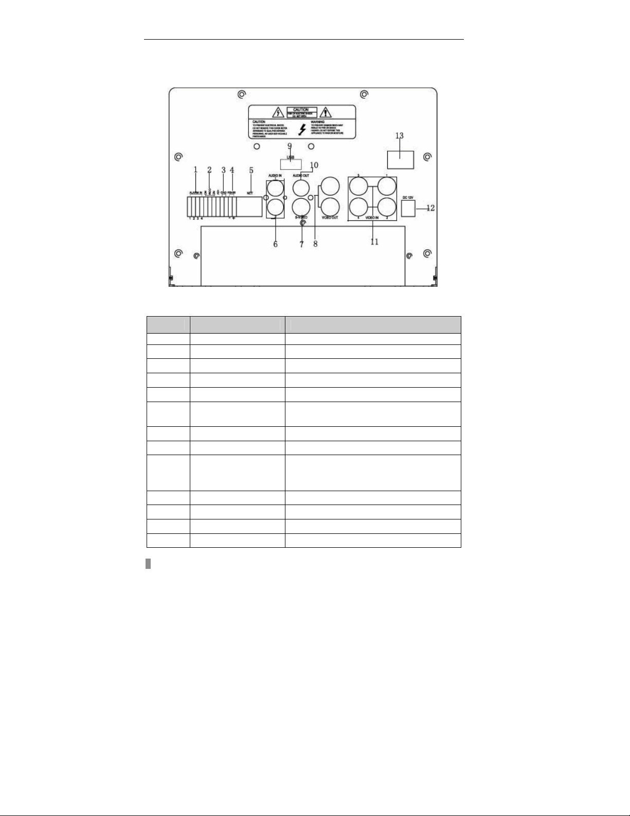
2.3 Rear Panel
Layout subject to change, may be slightly different from your model.
The rear panel sketch and interface buttons are shown as Fig 2.2
Fig 2.2 Back Panel
Items Names Functions
1 ALARM IN Connect to external sensor 1-4
2 ALARM OUT
3 GND
4 RS485
5 NET(RJ45 PORT)
6 AUDIO IN
7 S-VIDEO
8 VIDEO OUT
Relay output. Connect to external alarm.
Grounding
Connected to PTZ speed domes
Connect to internet
Audio input 1-2, connect to MIC or other
audio capture devices
S-Video output, connect to monitor
Connect to monitor
To connect mouse or external USB
9 USB PORT
devices like USB flash, USB HDD for
backup or update firmware
10 AUDIO OUT
11 VIDEO IN
12 POWER INPUT
13 POWER SWITCH
Audio output, connect to speakers
4ch Video input
DC 12V
Power on/off
8

QSTD5304 Digital Video Recorder User Manual
2.4 Remote Control Introduction
2.4.1 Using Remote Control
Notice: Please note that Remote Control is not a standard part of this DVR. Your
package might not include it.
To setup Remote Control:
1. Open the battery cover of Remote Control.
2. Put in two AAA batteries with poles aligned correctly.
3. Replace the battery cover.
If the Remote Control does not work, please check the following:
− Are the batteries positioned correctly?
− Do the batteries still have power?
− Is something blocking the Infrared signal between the
Remote Control and the DVR?
− Are signals transmitted by other devices interfering with
the Remote Control?
Notice: If none of the above problems apply, please contact Q-See to replace the
remote control.
2.4.2 Remote Control
The layout of the remote control is shown in Fig. 2.3.
Fig 2.3 Remote Control
9

QSTD5304 Digital Video Recorder User Manual
The functions of the buttons on the Remote Control are described in the
table below:
Items Names Functions
1 Power Button
2 INFO Button
Start shutdown to stop firmware running. Do it
before powering off.
Get information about the DVR like firmware
version, HDD information
3 REC Button To record manually
Number and Letter
4
Buttons
Input numbers and letters or choose camera
5 Multi-Screen Button To choose multi-screen display mode
6 SEARCH Button To enter file search mode
7 MENU Button To enter menu
8 ENTER Button To confirm the choice or setup
9 Direction Button Move cursor in setup or move PTZ cameras
10 +/- Button To increase or decrease the value in setup
11
Playback Control
Button
To control playback, Fast
forward/rewind/stop/single frame play
12 AUDIO Button To enable audio output in live mode
13 Auto Dwell Button To enter auto dwell mode
Press the button to change input mode.
14 A Button
Including switches among capital letter, small
letters, numbers and special symbols
To control PTZ camera
15 PTZ Control Button
Move camera/ZOOM/FOCUS/IRIS/SPEED
control
10

QSTD5304 Digital Video Recorder User Manual
Fig 3.2 Main
CHAPTER 3 Basic Operation Guide
3.1 How to Start DVR
Notice: Before powering on the unit, please make sure the power input matches the local
power voltage.
To start the DVR:
STEP1 Connect the DVR to AC adaptor and plug in.
STEP2 Turn on the DVR.
STEP3 Wait for the DVR to initialize.
After DVR is powered on, ‘STARTING……’ appears on the screen, which
indicates the DVR is initializing.
After ‘WELCOME’ is displayed, you enter into live display mode. You can
press the "Menu" button to enter Main Menu.
The symbols displayed on the screen are explained in the following table:
Symbol Meaning Symbol Meaning
LIVE Live picture mode REC Manual recording
A Sensor recording M Motion recording
DISK
3.2 Main Menu Setting
There is an administrator setup in the DVR. The administrator has control
over all settings. The username is "Admin", and default password is "123456".
Steps of entering the Main Menu are:
Notice: The instructions in the examples, are the steps using the Remote Control. If using
a mouse the operation may be easier, you would follow the instructions in dialogue boxes and
navigate through menu items. If using the front panel buttons you cannot control PTZ
cameras, but the other operations are the same as the remote control.
STEP1 Press the "Menu" button, input username and password in the
Login interface (as Fig. 3.1), and then you will see the Main Menu (as Fig.
3.2).
Percentage of hard
drive used
V-LOSS Video loss
Fig 3.1 Login
STEP2 Move the cursor, and the selected items will be highlighted in
yellow
STEP3 Press "Enter" key to enter the sub-menu, and press "Menu" key to
get back to Main Menu
11

QSTD5304 Digital Video Recorder User Manual
Fig 3.4 B
asic C
onfiguration
The structure of the main menu is shown in Fig 3.3.
BASIC CONFIG
LIVE CONFIG
RECORD CONFIG
ALARM CONFIG
MENU
PTZ CONFIG
USER CONFIG
NETWORK
MANAGER TOOLS
Fig 3.3 Structure of Main Menu
3.2.1 Basic Configuration
Basic Configuration menu is shown as Fig. 3.4.
MOTION ALARM
SENSOR ALARM
OTHER ALARM
BASIC CONFIG
IP CONFIG
DDNS CONFIG
SHUTDOWN SYSTEM
DISK MANAGEMENT
SYSTEM LOG
SYSTEM INFO
UPDATE FIRMWARE
LOAD DEFAULT
CLEAR ALARM OUT
Fig 3.5 Time adjustment
1. VIDEO FORMAT
There are two video formats: NTSC and PAL. Please select according to your
area, NTSC is used in the USA.
12
Fig3.5 Time Adjust

QSTD5304 Digital Video Recorder User Manual
2. TIME POSITION
This item is for setting up the position of the time on the display. There are
three options:
•
TOP: Time is displayed on top of the screen.
•
BOTTOM: Time is displayed at the bottom of the screen.
•
NO: Time is not displayed on the screen
3. Language
There are languages to be selected English or Spanish.
4. DVR NAME
Users can set DVR name with letters from ‘a’ to ‘z’ or numbers from ‘0’ to ‘9’.
STEP1 Press "A" button to switch the inputting mode from letters to
numbers
STEP2 Modify the DVR name.
STEP3 Press "Enter" key to confirm the operation.
5. DVR ID
DVR ID consists of three numbers.
STEP1 Move the cursor to the item.
STEP2 Press "Enter" key to modify numbers.
STEP3 Enter three numbers, and then press "Enter" key to confirm the
modified entry.
STEP4 Press "OK" button to confirm the operation.
6. DATE FORMAT
There are three date formats:
•
Asian Date format: YY/MM/DD
•
European Date format: DD/MM/YY
•
American Date format: MM/DD/YY
7. TIME ADJUSTMENT
Time Adjustment menu is shown as Fig. 3.5. Please stop recording before
adjusting time.
STEP1 Move the cursor to the item.
STEP2 Modify numbers by using "+" and "-" buttons.
STEP3 Press "Enter" key to confirm the operation.
Notice: If you set a time that is before the current displayed time, the record between the
adjusted time and current time will be deleted automatically.
8. BUZZER ALARM
There are seven options to choose: always (continuous buzzer), 5 seconds,
10 seconds, 30 seconds, 1 minute, 2 minutes and 4 minutes.
13

QSTD5304 Digital Video Recorder User Manual
3.2.2 Live Configuration
Live Configuration menu is shown in Fig. 3.6.
Fig 3.6 Live Configuration
1. CHANNEL
STEP1 Move the cursor to the item.
STEP2 Press "Enter" key to select the channel
2. CHANNEL NAME
User can set the channel name with letters from ‘a’ to ‘z’ or numbers from ‘0’
to ‘9’.
STEP1 Press "A" button to switch the inputting mode between letters and
numbers.
STEP2 Enter channel name.
STEP3 Press "Enter" key to confirm the operation.
3. SHOW NAME
If selecting "SHOW NAME", the camera name will be displayed in live view. If
unselecting "SHOW NAME", the camera name will not be displayed.
4. CHANNEL HIDE
If selecting "HIDE", the video from the channel will not display in live view, but
it will still be recorded. If unselecting "HIDE", the video will be displayed.
5. CHANNEL COLOR
Change the values of contrast, brightness, saturation, and hue of the picture.
6. COPY CONFIG TO
Copy the configuration of one channel to any other selected channels. By
selecting “ALL”, users can copy the configuration to all other channels.
STEP1 Select the channel you want to copy this channel to, or select ALL
to copy the configuration to all other channels.
STEP2 Press "COPY" button.
STEP3 Press "Enter" key to confirm the operation.
14

QSTD5304 Digital Video Recorder User Manual
3.2.3 Record Configuration
Record Configuration menu is shown in Fig. 3.7.
Fig3.7 Record Configuration
1. VIDEO RESOLUTION
This unit supports CIF format.
Resolutions of different video formats are: PAL: 352*288(CIF);
NTSC: 352*240(CIF)
2. RECYCLE
Checking the "RECYCLE" option means once the hard drive is filled the DVR
will continue to record by covering the previous recording automatically,
starting with the oldest. If you do not check "RECYCLE", recording will stop
once the hard drive is full.
3. PRERECORD TIME
Prerecord time refers to the amount of time recorded from memory before the
alarm was triggered. There are two options: 5 seconds and 10 seconds.
4. TIME STAMP
If selected, record time will be displayed on the bottom of the screen at
playback
5. CHANNEL
STEP1 Move the cursor to the item.
STEP2 Press "Enter" key to switch the channel and select.
6. VIDEO QUALITY
There are five options: lowest, lower, medium, higher and highest. The higher
the picture quality, the clearer the image is, but more hard drive space will be
taken up.
7. AUDIO
If you check "AUDIO", DVR will record audio with video recording. Otherwise,
it will not record audio.
Notice: • The default setting is that Audio input1 matches channel1 and Audio input2
matches channel2.
•
to the corresponding channel.
When playing back the record, please press "AUDIO" button to switch the sound
15

QSTD5304 Digital Video Recorder User Manual
8. SCHEDULE RECORD
Schedule Record Setup is shown as Fig. 3.8.
Fig 3.8 Schedule Setup
STEP1 Move the cursor to "SCHEDULE RECORD" option
STEP2 Check "SCHEDULE RECORD", and the “Setup” window will pop
up.
STEP3 Press "Setup" to enter the Schedule Setup menu.
Press "ESC" button on the front panel to get back to upper menu.
STEP4 In the Schedule Setup menu, move the cursor to select a day, and
check “whole day” if you want to record all of the time.
STEP5 If you only want to record certain time periods press "Enter" key to
set up time.
STEP6 Press "+" and "-" buttons on the front panel to modify the time.
Notice: When you use the mouse, you need roll the middle wheel to modify the time.
STEP7 Press "Enter" key to confirm the setup.
On weekday and holiday, you can select whole day or set four periods in a
day to record.
9. FRAME RATE SETUP
Frame rate is the number of pictures recorded each second. If choosing 15,
the picture-recording rate is 15 frames per second.
User can set frame rates based on the record mode.
If the video format is NTSC, there will be five frame rates to choose: 1, 3, 7,
15 and 30. The maximum frame rate is 30.
If the video format is PAL, there will be five frame rates to choose: 1, 3, 6, 12
and 25. The maximum frame rate is 25.
10. COPY TO
This option allows you to copy the settings of this channel to other selected
channels.
16

QSTD5304 Digital Video Recorder User Manual
3.2.4 Alarm Configuration
Alarm Setup menu is shown as Fig. 3.9.
Fig 3.9 Alarm Configuration
MOTION ALARM
If you select Motion Alarm in Alarm Configuration the submenu shown as Fig.
3.10 will be displayed.
Fig 3.10 Motion Alarm Configuration
1. HOLD TIME
This sets the continued recording time after an alarm is triggered. There are
two options: 1 minute and 2 minutes. It also determines the interval between
motion detection events. If the HOLD TIME is 1 minute, if new motion is
detected within this period it will be considered part of the previous event
instead of the start of a new event.
2. CHANNEL
STEP1 Move the cursor to the channel.
STEP2 Press "Enter" key to switch the channel and select.
3. DETECTION
Checking "DETECTION" means to enable motion detection, not checking
means motion detection will not be enabled.
4. SENSITIVITY
This is the sensitivity level of the motion sensors.
The range is from ‘1’ to ‘8’. The higher the value, the more sensitive.
17

QSTD5304 Digital Video Recorder User Manual
5. TO REC
If selecting "TO REC", DVR will record when motion is detected. If not, DVR
will not record when motion is detected.
6. ALARM OUT
There are two options: ALARMOUT1 and BUZZER.
•
When ALARMOUT1 is selected and an alarm is triggered, the DVR will
give send signal to the alarm out port.
•
When BUZZER is selected and the sensor is triggered, DVR will give a
buzzer alarm.
When the alarm output is unselected, DVR will not send an alarm.
7. SCHEDULE
This is the schedule for the motion detection. The default schedule is
everyday. Press "SETUP” button to set the motion detection schedule.
8. AREA
STEP1 move the cursor to “setup”.
STEP2 Press "SETUP" button to enter the Area Setup submenu.
It displays the selected detection area (refer to Fig. 3.11). There
are four options:
− ALL: motion anywhere in the area will be detected as shown
in the picture.
− CUSTOM: You can select part of the area to be detected.
− NULL: No area will not be open to motion detection
− BACK: Go back to Motion Alarm Configuration menu.
Fig 3.11 Detection Area Setup
Sub-steps for manually selecting the detection area are described below:
1. In the Area Setup submenu, choose "CUSTOM" option.
2. Press "Enter" key to confirm the operation.
3. Press "Up", "Down", "Left" and "Right" buttons to choose the
area which needs to be detected
4. Press "Enter" key to select or cancel the area.
5. Press "Esc" button to confirm the option and exit "CUSTOM"
option.
STEP3 Press "BACK" option to go back the Motion Alarm Configuration
menu.
18

QSTD5304 Digital Video Recorder User Manual
Notice: If continuous recording mode, manual record and alarm record are activated at
the same time. The alarm events can be found in Search by Event”, please refer to the
‘3.3.2 Search’ function in ‘3 Search by Event’.
9. COPY TO
Use this option to copy the settings of this channel to any other selected
channel.
SENSOR ALARM
Sensor alarm submenu is shown as Fig. 3.12. Every Sensor matches one or
more channels.
Fig 3.12 Sensor Alarm Configuration
1. HOLD TIME
This sets the continued recording time after an alarm is triggered. There are
two options: 1 minute and 2 minutes. It also determines the interval between
motion detection events. If the HOLD TIME is 1 minute, if new motion is
detected within this period it will be considered part of the previous event
instead of the start of a new event.
2. SENSOR
STEP1 Move the cursor to the "SENSOR" option.
STEP2 Press "Enter" key to switch the Sensor.
3. DETECTION
This is the switch of the sensor alarm. If you check "DETECTION", DVR will
begin detecting. If you do not check it, the detection function is disabled.
4. TYPE
Press "Enter" key to enter the sub-menu. There are two options: NO and NC.
‘NO’ means normal open. If ‘NO’ is chosen, the DVR will be triggered when
the alarm when the voltage drops.
‘NC’ means normal close. If ‘NC’ is chosen, the DVR will be triggered when
the alarm sends a high voltage charge.
5. TRIGGER RECORD
One channel can connect with one sensor. But one sensor can trigger one or
more channels.
STEP1 Move the cursor to "TRIGGER RECORD" option.
STEP2 Select the channel you want that sensor to trigger.
STEP3 Press "Enter" key to confirm the operation.
19
 Loading...