

Page 1
User Manual
MODEL QD6523ZH
Outdoor Intelligent Pan-Tilt-Zoom Dome Camera with 23x Optical Zoom
and Internal Heater
1
Page 2

TABLE OF CONTENTS
Introduction 4
Thank You for Choosing a Q-See Product!
All of our products are backed by a conditional service warranty covering all
hardware for 12 months from the date of purchase. Additionally, our products also
come with a free exchange policy that covers all manufacturing defects for one
month from the date of purchase. Permanent upgrading service is provided for the
software and is available at www.Q-See.com.
Be certain to make the most of your warranty by completing the registration
form online. In addition to warranty and technical support benefits, you’ll receive
notifications of product updates along with free downloadable firmware updates for
your DVR. Register today at www.Q-See.com!
Please see the back of this manual for exclusions.
Features 5
Before Installing 5
Setting Baud Rate and Address 6
Setting Camera Address 7
Setting Baud Rate 7
Setting Parity 7
Connecting the Camera 8
Power and Video Connection 8
PTZ Control Connection 9
Installing the Camera 10
Before Installing Your Camera 11
Operation 13
System Setting Menu 15
Display Setting Menu 16
Camera Setting Menu 16
Function Setting Menu 18
Alarm Setting Menu 19
Troubleshooting 21
Specifications 22
Q-See Product Warranty 23
Questions or Comments? Contact Us 23
© 2013 Q-See. Reproduction in whole or in part without written permission is
prohibited. All rights reserved. This manual and software and hardware described
herein, in whole or in part, may not be reproduced, translated, or reduced to any
machine-readable form without prior written approval.
Trademarks: All brand names and products are trademarks or registered
trademarks of their respective owners.
Q-See is a registered trademark of DPS, Inc.
Disclaimer: The information in this document is subject to change without notice.
The manufacturer makes no representations or warranties, either express or
implied, of any kind with respect to completeness of its contents.
Manufacturer shall not be liable for any damages whatsoever from misuse of this
product.
2 3
Vers 1.0 07/03/13
Page 3

INTRODUCTION
This manual is written for the QD6523ZHH pan-tilt-zoom camera and was accurate
at the time it was completed. However, because of our ongoing effort to constantly
improve our products, additional features and functions may have been added
since that time and on-screen displays may change. We encourage you to visit our
website at www.Q-See.com to check for the latest product announcements. You
can also find technical details and an electronic version of this manual on our online
Knowledge base online at www.Q-See.com/support.
Throughout the manual we have highlighted warnings and other important
information that will assist you in operating your new system in a safe and troublefree manner. Please take the time to read and follow all instructions and pay
attention to alerts as shown below:
IMPORTANT! Red boxes with this icon indicate warnings. To
prevent possible injury or damage to the product, read all warnings
before use.
NOTE! Text in blue boxes with the Information icon offer additional
guidance and explanations about how to make the most out of your
system.
For your safety and to protect your camera
To prevent damage to your Q-See product or injury to yourself or to others, read
and understand the following safety precautions in their entirety before installing or
using this equipment.
n
Care should be taken during transportation, storage and installation of this camera
WARNING! ELECTRIC SHOCK RISK!
FEATURES
Your camera offers the following features:
nHigh quality video using 1/4” Sony Exview HAD CCD-II
nAutomatically recognizes Pelco-D and Pelco-P protocols
n650 TV lines of resolution daytime, 700 TV lines or resolution at night.
nWeatherproof IP66 Rating
nColor vision to 0.01Lux, Night (B/W) vision to 0.001Lux
nAutomatic focus and light levels with manual override
nVandal-proof design.
nHeater/blower for operation down to -40° (F or C)
nRS485 control.
nExternal alarm input.
n3.9-89.7mm zoom lens
n360° continuous horizontal rotation with 90° vertical movement.
nLow-noise camera rotation motor.
nMemory function retains settings in case of power loss.
nHorizontal scanning: 360° rotation
n300°/second rotation speed, 200°/second tilt speed
nRotation speed can adjust based on focal length
nPTZ scanning precision ± 0.5°
n23x optical zoom, 16x digital zoom
nCamera can be controlled with an optional keyboard
BEFORE INSTALLING
Your camera is shipped with a foam
collar inside the glass cover. This
collar protects the camera mechanism
from damage during shipping. It
must be removed and discarded
before powering up or operating the
camera in order to avoid damaging the
mechanism.
to avoid rough handling, dropping, or other abuse in order to prevent damage to the
optics or components inside the camera.
n
Camera should be installed in accordance with electrical standards including keeping
the camera and cable away from high voltage, using a transient voltage surge
protector (UL-1449) and using only the rated power supply.
n
Do not use strong or abrasive cleaners on camera body or lens. Use a damp cloth
for cleaning the housing and a lens cloth for the optics.
n
Do not attempt to disassemble the camera beyond removing the case to adjust
settings. Only authorized, trained technicians should service this camera.
n
The camera should not be immersed in water and should be mounted in a sheltered
location. Do not point camera directly at the sun or other strong light source.
Use the included torx (star) wrench to
loosen the three retaining bolts securing
the camera cover to the housing. You
should not remove the bolts from the
cover itself. Take care to not leave
fingerprints or debris on the inside of
the clear cover, or within the camera
housing while it is open.
Remove and discard the foam housing and then reattach the cover to the housing,
making sure that the seal is tight in order to maintain the camera’s weatherproofing.
If you will be changing your camera’s address or making other changes using the
internal DIP switches (see next page), then you should do so before closing up the
camera.
Remove Screws (x3)
4 5
Page 4
SETTING BAUD RATE AND ADDRESS
Unlike conventional security cameras,
PTZ cameras require an address and
a connection speed to be set in order
for them to properly operate. The
default settings for this camera are
an address of “1” and a baud rate of
9600 and using the Pelco-D protocol.
However, if your camera came as part
of a bundle, its address may have been
set to something other than “1”. Check
the Quick Install Poster that came
with your bundle for specific details.
If you are connecting the camera in
accordance to the instructions included
with the bundle, you should not have
to change any of its settings. In either
case, if you are only using a single
PTZ camera you generally do not have
to make any changes and you may
proceed to the next section. Please
consult your DVR’s manual for required
settings.
If you need to change your camera’s settings, they are made using a DIP (dual in-line
package) switch panel located within the camera itself. In general, it is easier to do
this before connecting the camera, but in some cases, you may need to change
settings while the camera is connected to the DVR. In this case, please make a
temporary connection by following the procedures laid out in the next section,
Connecting the Camera. Please be advised that adjusting these settings after
the camera is mounted can be difficult due to the panel potentially being inaccessible
because of location, position, etc.
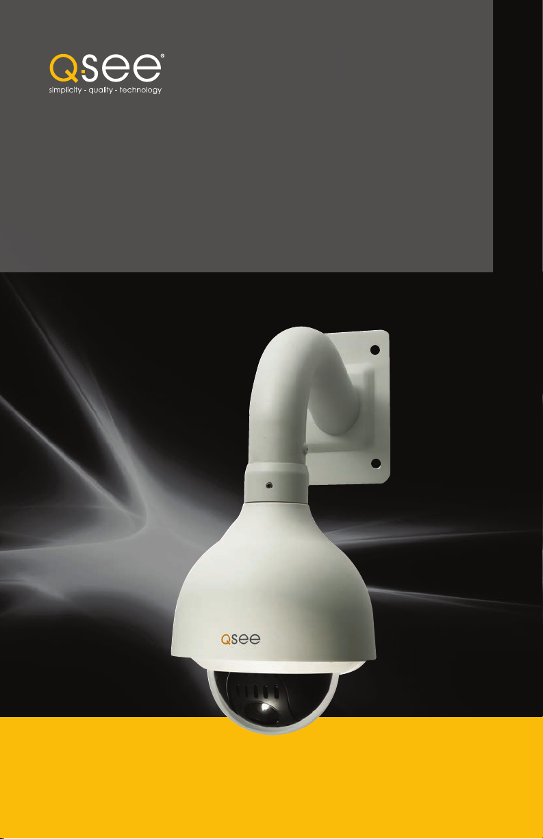
To access the panel, one must remove the clear dome by first twisting the metal
collar around the dome counterclockwise and then removing the three screws
securing the plastic dome to the camera. Take care to not scratch the clear dome
while removing it. The circuit board on which the DIP switches are mounted is
visible below the camera in the bottom picture.
DIP switches are binary - meaning that they are either On or Off. Different
combinations of ones and zeroes on the board produce different settings. On
the QD6523ZH, there are a total of 12 DIP switches.The first eight are for setting
the address of the camera.The next block of four switches controls the baud
rate (switches 1 and 2) - which is the speed in bits per second at which the DVR
communicates with the camera for control. Switches 3 and 4 are for setting parity
which some DVRs use to detect for communication errors.
Your camera is set to a baud rate of 9600. This will allow you to effectively control
the camera up to 300 feet away. Areas with electronic interference may require
heavier or shielded cabling. The higher the setting (may be required by some DVRs),
the shorter the control distance.
Remove Screws (x3)
SETTING CAMERA ADDRESS
Switch (8 digits)
Address
1 2 3 4 5 6 7 8
1 OFF OFF OFF OFF OFF OFF OFF OFF
2 ON OFF OFF OFF OFF OFF OFF OFF
3 ON ON OFF OFF OFF OFF OFF OFF
4 OFF OFF ON OFF OFF OFF OFF OFF
5 ON OFF ON OFF OFF OFF OFF OFF
6 OFF ON ON OFF OFF OFF OFF OFF
7 ON ON ON OFF OFF OFF OFF OFF
8 OFF OFF OFF ON OFF OFF OFF OFF
9 ON OFF OFF ON OFF OFF OFF OFF
10 OFF ON OFF ON OFF OFF OFF OFF
11 ON ON OFF ON OFF OFF OFF OFF
12 OFF OFF ON ON OFF OFF OFF OFF
13 ON OFF ON ON OFF OFF OFF OFF
14 OFF ON ON ON OFF OFF OFF
15 ON ON ON ON OFF OFF OFF OFF
16 OFF OFF OFF OFF ON OFF OFF OFF
SETTING BAUD RATE
Some DVRs may require specific
connection speeds. Check your
system’s manual for proper settings.
Baud
Switch Number (BIT)
Rate
1 2
1200bps ON ON
2400bps OFF ON
4800bps ON OFF
SETTING PARITY
Some DVRs may require the use of
parity. Check your system’s manual for
proper settings.
Parity Switch Number (BIT)
1 2
NONE ON ON
EVEN ON OFF
ODD OFF ON
NONE OFF OFF
9600bps OFF OFF
EXAMPLE
The illustration on the right shows
the settings as those in the photo on
the preceding page. All switches are
set to the OFF position:
nAn address Channel 1
nA baud rate of 9600
nParity set to NONE
ON
1 2 3 4 5 6 7 8 9 10ON1 2 3 4
Camera Address
Baud
Rate
OFF
Parity
6 7
Page 5
CONNECTING THE CAMERA
Serial PortSerial Port AdvancedAdvanced
P.T.ZP.T.Z
DefaultDefault
ApplyApply ExitExit
CH Enable Address Baud Rate Protocol Simulative Cruise
1
2
3
4
CH Enable Address Baud Rate Protocol Simulative Cruise
1
2
3
4
AllAll
11
22
33
44
24002400
96009600
96009600
96009600
PELCODPELCOD
PELCOPPELCOP
PELCOPPELCOP
PELCOPPELCOP
96009600 PELCOPPELCOP
Before you can operate the camera, you must connect it to a system which can
support PTZ operations. There are three sets of connectors - power, video and
the bare control wires. This latter connection is covered on the next page. We
recommend connecting the camera (at least temporarily) to the DVR to test your
settings and connections before mounting it in its final location.
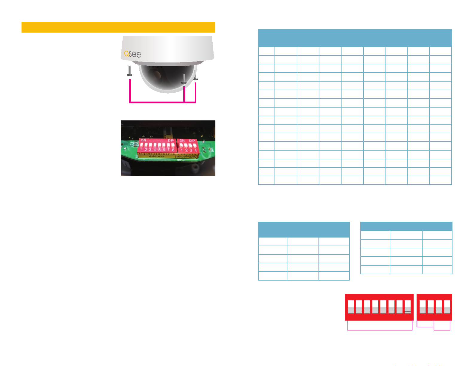
POWER AND VIDEO CONNECTION
STEP 1. Connect the BNC and
power leads from the camera
to the matching connectors on
a video/power siamese cable
(Note: these may need to be
purchased separately if your
camera was not included as part
of a bundle package).
IMPORTANT! When connecting the power and video cable between
the camera and the DVR, the “male” power end (red plug) connects to the
matching power lead on the camera.
STEP 2. Connect the power lead on
the other end of the video/power
cable to a power adapter or power
distribution panel. Make certain
that the power supply is rated for
24 volts and 3 amps.
Weather shield on Video
connector (top) omitted
for clarity.
PTZ CONTROL CONNECTION
In addition to connecting the power and video leads to the camera, you must also
connect the two control wire leads to the RS485 ports in the alarm block on the
back of the DVR. These blocks can vary in layout as shown below, but the ports
used by your DVR are generally labelled “RS485”, “RS422”, “PTZ” or “P/Z”.
As seen in the picture on the upper right, the wire leads
from the camera are two different colors and are labeled.
They are also pre-installed into a block which plugs into a
matching receptacle on the extension cable. The control
wire leads at the other end of the extension cable must
be inserted into the ports on the back of the DVR. In the
case of the RS485 ports being marked as positive (+) and
negative (-), the wire designated RS485A (red tip) is the
positive lead while the wire marked RS485B (black tip) is
to go into the negative port. Your camera comes with a
connector PTZ blocks either have small screws above
each port to secure the wire or require a lock above the
port to be depressed with an object like a small screw
driver in order to fully insert the wire. In the latter, when the
lock is released, an internal clamp will keep the wire firmly
secured in the port. If the wire can easily be removed from
the port, then it isn’t secure and you can experience control
difficulties until it is properly attached. Space permitting,
multiple PTZ cameras may be connected to the same ports.
STEP 3. Connect the BNC connector
on that same end of the cable to
a Video In port on the back of the
DVR.
You can now plug the camera’s power
adapter into a surge protector and turn it on.
To protect your investment, we STRONGLY
recommended using a surge protector that
is UL-1449 rated, for a clamping voltage of
330 or lower, a Joule rating of at least 400 and a response time of 10 nanoseconds
or less.
There are five bare wires labelled “Alarm” and these are used to connect an external
alarm to the PTZ camera. Use of an alarm will be covered later in this manual.
These wires may be ignored if an alarm will not be used.
8 9
AUDIO IN VIDEO IN
1 3
2 4
1 3
2 4
Some examples of PTZ blocks. One using screws (left) and two using spring-loaded locks.
They will each require a different address
which is set up using the DIP switches
as covered in the previous section.
To connect your camera to the DVR
over a distance, you will need to use
both a video/power cable and a pair of
24-gauge wires to connect to the alarm
block. If your camera came as part of a
package, these wires may be included
separately or as part of the video and
power cable.
Once you have made your connections, you will need to make settings on the DVR
in order to control it. You will need to consult your DVR’s manual for this procedure,
but a sample screen (from a Q-See QT-series DVR) is shown immediately above.
Page 6

INSTALLING THE CAMERA
When installing your camera, it is important to select a proper site not only for field
of view, but for other considerations as well:
Distance from viewing/recording device. The further the camera is from
the DVR or monitor, the higher the chances of signal degradation. Typical 75Ω
Video Cable provides acceptable signal at distances up to 200’ (30m). At greater
distances, UL-Listed shielded RG59 should be used. The camera’s power supply
should be located as near to the camera as possible when the distance exceeds
200’ as the power level will drop over extended distances resulting in a decrease in
video quality.
Do not place near high voltage wires or other sources of electrical
interference. Electrical interference will degrade the quality of the signal.
Place camera out of reach to avoid damage.
Avoid direct exposure to weather. Do not place the camera where rain or snow
will hit the lens directly nor should the camera be placed so that the sun or bright
light shines directly into the lens. Your camera is weatherproof, but it will not work
when submerged in water. Ensure that all power and video connections are not
directly exposed to water and are protected from the elements.
Do not place camera behind a window. If there is a light source behind the
camera, it can cause a reflection in the window that will obscure events on the
other side of the glass.
Light levels should be approximately the same between camera and target
area. A camera in a brightly-lit area looking into a shaded area, or vice versa, may
produce inadequate results.
The above are guidelines and the
optimal location for your camera will
depend on your unique circumstances.
As a general rule, the area highlighted in
green in the picture to the right indicate
the best type of location to mount your
camera. It is sheltered from rain or snow
and offers good sight lines to allow your
camera to monitor a wide area. Because
your camera is weatherproof, it requires
less protection than weather-resistant
cameras and it can be placed in more
exposed locations if needed. Keep in
mind that this camera is designed to
operate between -40°F to 140°F (-40°C
to 60°C) with a relative humidity of up to
90%) and consider wind chill and other environmental factors when selecting your
location.
Your camera comes with both a ceiling and wall mount. Where you locate your
camera will determine which mount you will need to use. The mounting surface
must be sturdy and able to hold at least five times the camera’s total weight of
approximately 5 pounds.
BEFORE INSTALLING YOUR CAMERA
Use the included torx (star) wrench to loosen
the three housing bolts to open the lens cover.
We have also included fabric gloves with your
camera to help you prevent getting fingerprints
or scratches inside or outside of the clear glass
dome or camera lens. Do not remove the bolts
from the cover.
Remove the foam shipping insert from around the camera head. This protective
packaging will interfere with camera movement. Then close the camera. Take care
to not touch or move the camera mechanism or leave fingerprints or dust on the
inside of the lens cover during this process.
MOUNTING THE CAMERA
x3
Your camera is designed to be mounted on a wall using the included bracket.
1. Run the power/video/data extension
cable from the DVR to the camera’s
location.
5
2. Use the mounting bracket to mark the
position for the mounting holes. Ensure
that the camera will be horizontal by
using a spirit or bubble level. Also mark
location of hole for cables to pass
through the mounting surface.
3. Drill the mounting and cable holes.
4. Insert included mounting anchors into
surface.
5. Screw mounting collar onto camera
body.
6. Feed the cables through through the
mount and out the hole in the back
before securing the camera/collar
assembly to the mounting bracket.
7. Tighten the three retaining screws on the
7
9
collar so that the camera housing does
not turn.
8 Connect the camera cables to the
extension cable.
9. Secure the camera and mount assembly
to the wall using the included bolts.
IMPORTANT! Do not allow the camera cable to be subject to
pinching, tight bends or other severe constriction as part of its final
installation position as this can damage the cable over time leading to
signal loss or potential fire hazard.
Take precautions to ensure a clear work area below the camera mounting point
during installation as a falling camera can cause injury or damage.
10 11
Page 7
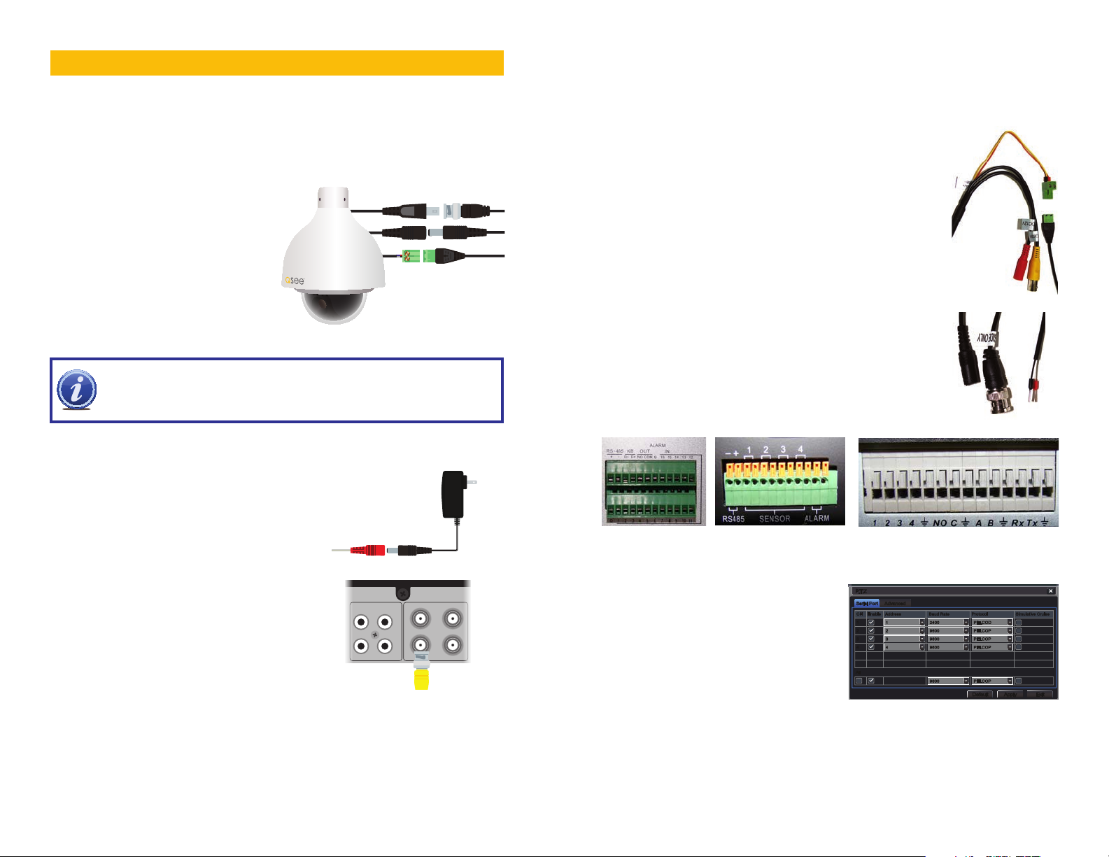
WHICH CABLE TO USE?
SaveSave
Zoom
Focus
Iris
Zoom
Focus
Iris
Speed: 5Speed: 5
No.No.
11
02020101 0303 0404 0505 0606 0707 0808 AllAll
Your cabling needs will depend on the distance between your camera and your
DVR. Q-See offers several cables to fit specific needs. These may be purchased
from the same location as where you bought your camera, or on our website:
www.q-seestore.com
Q-See Model
Number
QS50B (50’)
QS100B (100’)
QSVRG60 (60’)
QSVRG100 (100’)
QSVRG200 (200’)
QS59500 (500’)
QS591000 (1000’)
Maximum Run Length 180’ 800’ 800’
Quality Output Standard High High
Type 75Ω Video Cable RG-59 RG-59
Shielded No Yes - UL Rated Yes - UL Rated
Plenum Rated No No No
Pre-Attached Connector
Video BNC BNC None
Audio N/A N/A N/A
Power 2.1mm 2.1mm None
Usage Indoor/Outdoor · Do
Indoor/Outdoor · In-wall or along wall
not run inside walls or
underground
To extend the RS485 data cable, you may use any 24 gauge wire, including Cat 5.
To maintain video quality:
· Video quality is always enhanced by using shielded cables.
· Always check state and local laws before installing cameras. (2011 NEC 820.44)
· To prevent video signal loss, run one continuous cable between the camera and
DVR for best results. If more length is required, use the minimum number of interconnection points possible.
Other notes:
· If a cable run exceeds 800ft, we recommend using RG-6 coaxial cable which is
available at most retail building supply companies.
· If your home or business is pre-wired with CAT-5 cable, then you can run up to
1000ft. Powered video baluns are required for easy installation.
OPERATION
Your camera can be controlled manually through a PTZ keyboard (if supported
by your DVR), or by using the PTZ controls on the DVR to which it is connected.
Depending on the software used, it is also possible to control the PTZ camera
remotely when you are logged into the DVR via the Internet, a remote monitoring
program or a smartphone app.
The QD6523ZH is able to be programmed directly using its on-screen display but
most users prefer to use the DVR’s own control inteface to program cruises - also
called “scans” or “tours” on some systems - so that the camera w ill perform a set
search pattern of the surrounding area. Multiple cruises may be set up and each
can generally have up to 16 specific preset points. The exact numbers will depend
upon your DVR.
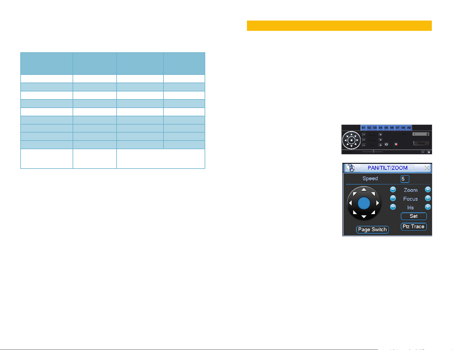
GENERAL CRUISE SETUP PROCEDURE
You will need to consult your DVR’s
manual for specific instructions on
creating preset points, cruises and
scans. That said, there are general
similarities in the process that can be
covered here to get you started. Most
involve the process of pivoting the
camera to the desired starting point and
saving that point. Then, by selecting
one or more points for the camera to
move to in sequence, a scan path is
built which is then saved. Often, multiple
paths can be saved within the DVR,
which can be selected for later use.
These points can be set using a special
PTZ keyboard, or by using the PTZ
controls on the DVR itself. Two such
on-screen interfaces are shown at right; the QT-Series (top) and QC-series (bottom).
In both examples, directional control is achieved by using the DVR’s mouse to
click on one of the directional arrows. As long as the arrow is held, the camera will
move in that direction. There are no horizontal stops and the camera can rotate
continuously if desired. The camera’s elevation is limited to 90°.
On both control panels there are controls for zoom, focus and iris (light level).
The QD6523ZH has a 23x optical zoom lens which will adjust between 3.9 and
89.7mm. The camera has an auto-focus feature but the user can also adjust it
to bring a specific item into focus. Likewise, the iris feature - which automatically
controls the amount of light entering the lens - can also be further adjusted manually
It is important to note that preset 95 is reserved for accessing the camera’s internal
12 13
menu and this will be covered on following pages.
Page 8
EXAMPLE 1: SETTING A CRUISE
This example is based on using a QT-Series DVR without an attached PTZ
keyboard. Your DVR’s specific commands may differ slightly. Please consult your
system’s manual.
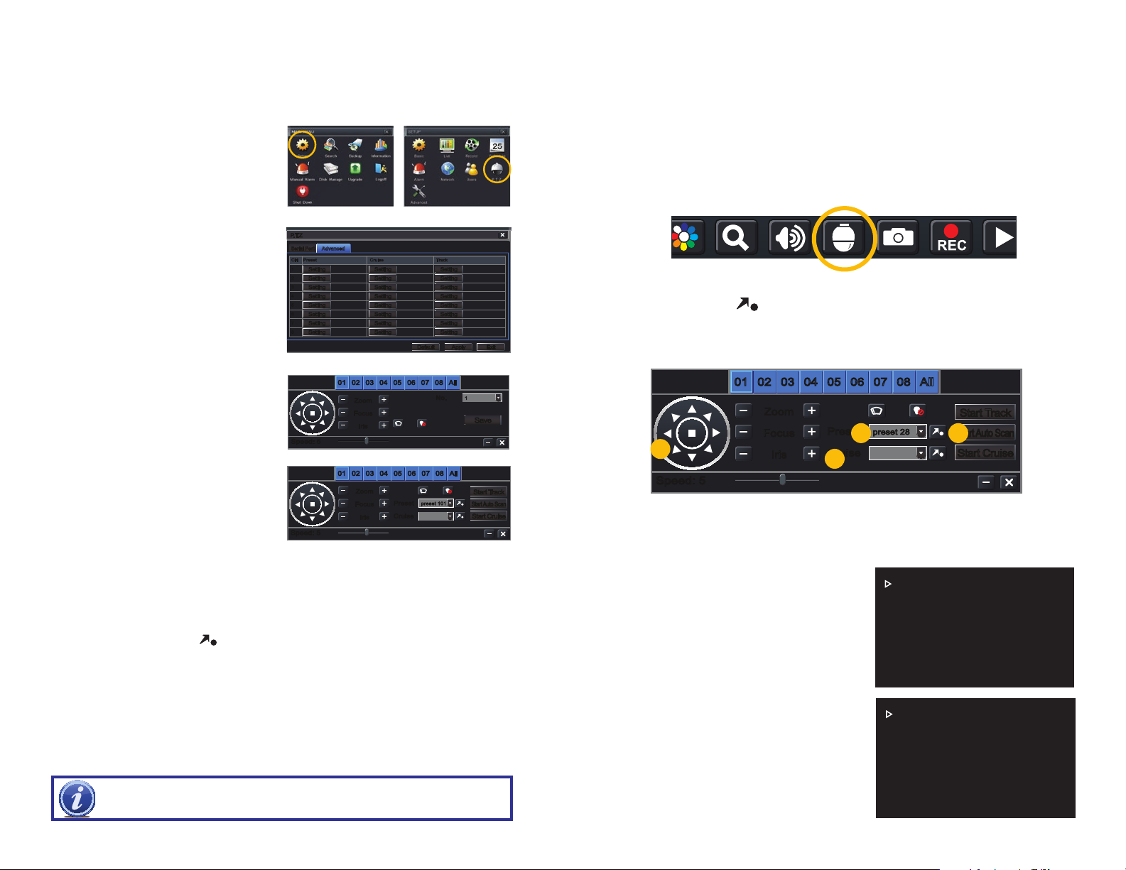
STEP 1. In your DVR’s PTZ settings
window, select the Advanced tab
and then Preset 1.
STEP 2. Rotate the camera to the
desired position using the arrow
controls.
STEP 3. Click Save
STEP 4. Select Preset 2.
STEP 5. Rotate camera to desired
second location.
STEP 6. Click Save
You may repeat Steps 4-6 for additional
positions if desired.
STEP 7. While still in the Advanced
P.T.ZP.T.Z
Serial PortSerial Port AdvancedAdvanced
CH Preset Cruise Track
CH Preset Cruise Track
1
1
SettingSetting
2
2
SettingSetting
3
3
SettingSetting
4
4
SettingSetting
5
5
SettingSetting
6
6
SettingSetting
7
7
SettingSetting
8
8
SettingSetting
SettingSetting
SettingSetting
SettingSetting
SettingSetting
SettingSetting
SettingSetting
SettingSetting
SettingSetting
DefaultDefault
SettingSetting
SettingSetting
SettingSetting
SettingSetting
SettingSetting
SettingSetting
SettingSetting
SettingSetting
ApplyApply ExitExit
tab, click on the Setting button in
the Cruise column for Channel 1.
This will open a new window.
STEP 8. Click Add.
STEP 9. Double-click on the new
cruise setting to begin loading
Speed: 5Speed: 5
02020101 0303 0404 0505 0606 0707 0808 AllAll
Zoom
Zoom
Focus
Focus
Iris
Iris
No.No.
11
SaveSave
your presets.
STEP 10. Click on the + button to
open the Preset pop-up window
and select your starting preset
point, speed and stop time.
Speed: 1-8 with 8 being the fastest
Speed: 5Speed: 5
02020101 0303 0404 0505 0606 0707 0808 AllAll
Zoom
Zoom
Focus
Focus
Iris
Iris
Preset
Preset
Cruise
Cruise
preset 101preset 101
Start TrackStart T rack
Start Auto ScanStart Auto Scan
Start CruiseStart Cruise
Time: This is the time the camera will stay pointed at this location.
STEP 11. Repeat for each preset - up to a maximum of 16 per cruise.
STEP 12. Click OK save your settings and close the windows until you reach
the PTZ Settings window. Click Apply to save all of the settings.
STEP 13. Open the PTZ controls from the Control Bar, select your cruise in the
pull-down and click
EXAMPLE 2: SETTING A TRACK
to begin.
An alternate method is to utilize the Track settings - also found in the Advanced
tab. Click the Track button for the right channel, use the directional controls to point
the camera at your desired starting point and then click Start Record. The DVR
will then record your movements, including delays at selected spots. Click Stop
Record to end. Clicking on Start Track in the PTZ control window will start the
camera on its track.
IMPORTANT! Preset 24 through 34 and 79 through 99 are reserved for
camera commands and cannot be used as preset points.
ADDITIONAL SETTINGS USING THE CAMERA’S ON-SCREEN MENU
The QD6532Z offers additional features that can be accessed through the DVR’s
PTZ menu, but which are actually programmed on the camera itself.
Accessing the Menu
The following instructions are shown using a QT-series DVR.
STEP 1.
Right-click on your screen to open the Control Bar.
STEP 2. Click on the PTZ Control icon.
STEP 3. Set the preset point (a)to 28 (95 may also be used)
STEP 4. Click the
STEP 5.
The on-screen menu will appear. You can navigate through it using the PTZ
directional controls (c). Use the Iris + button (d) as “Enter” to make selections
to the right of the Preset pulldown (b).
.
Use the right arrow in menus with multiple options.
02020101 0303 0404 0505 0606 0707 0808 AllAll
Zoom
Zoom
Preset
Focus
Focus
c
Iris
Iris
Preset
Cruise
Cruise
preset 28preset 28
a
d
Start TrackStart Track
Start Auto ScanStart Auto Scan
b
Start CruiseStart Cruise
Speed: 5Speed: 5
The Menus
When the On-Screen Display is activated, a menu with six options will be displayed.
The five menus all have submenus and other options. Most functions are selfexplanatory in nature. Selected features will be covered below.
Back will take you to the previous menu
while Exit will close out of the menu.
SYSTEM SETTING
DISPLAY SETTING
CAMERA SETTING
SYSTEM SETTING MENU
The first two selections show information
regarding the camera’s address, baud rate,
FUNCTION SETTING
ALARM SETTING
EXIT
and etc. These cannot be changed. The
language cannot be changed as well.
North: Exit the menu, point the camera
north and return to the menu. Select Set
North. “OK” will briefly flash on screen to
indicate that North has been set.
Restart: This will restart the camera and
it will go through its start-up cycle but will
not clear user settings.
SYSTEM INFORMATION
ADDR INFORMATION
SET NORTH
LANGUAGE: ENGLISH
FACTORY DEFAULT
RESTART
BACK EXIT
14 15
Page 9

DISPLAY SETTING MENU
You can determine what shows up on screen as the camera operates. It is
important to consider that whatever text the camera displays will appear in the
video recording as well.
Preset: When enabled, the camera will
display the identity of each preset point as
it cycles through them on the cruise.
Azimuth: This will display the horizontal (X)
and vertical (Y) position of the camera.
Position: An arrow will appear showing
the direction of “up”. The camera features
“auto flip” which means that it is moved
past 90° (pointing straight down), the camera will quickly rotate 180° and continue
to move the lens as directed. When the camera does this “flip”, the arrow will point
down indicating that directions are essentially reversed in this position.
Zoom Display: Shows the level of the optical zoom (up to 23x)
Inside Temp: This camera is equipped with an automatic heater/blower for extreme
temperatures. Temperatures below -40° can negatively effect operation.
Title Display: Not supported on this model.
CAMERA SETTING MENU
These settings allow you to adjust your camera’s video. Unlike alterations to the
display settings made on the DVR, these will have an effect on the recorded video.
There are two “pages” of options in this menu (shown below).
White Balance: Adjust this setting to
best fit the lighting conditions where your
camera is mounted. Your options are:
Automatic, Manual, ATW (Auto Trace
- camera monitors white areas and
automatically adjusts), Outdoor and Indoor.
PRESET :ON
AZIMUTH DISP :ON
POSITION :OFF
ZOOM DISP :OFF
INSIDE TEMP :OFF
TITLE DISP :OFF
BACK EXIT
WB SETTING
EXPOSURE SETTING
DAY/NIGHT SETTING
FOCUS SETUP
ZOOM SPEED
APERTURE
APERTURE CNT LEVEL
NEXT PAGE
BACK EXIT
DIGITAL ZOOM :OFF
PICTURE FLIP :OFF
FREEZE FUNCTION :OFF
CAMERA FACTORY DEFAULT
CAMERA RESTART
BACK EXIT
Exposure Setting: There are also two pages in this menu for the multiple settings
that can be made to optimize the video image. Settings can be changed using the
left and right directional arrows.
AE MODE :AUTO
GAIN SETTING :2
SHUTTER :1/50
IRIS SETTING :4
EXPOSURE COMP :8
SLOW SHUTTER :ON
NEXT PAGE
BACK EXIT
AUTO EXPOSURE (AE) MODE: Select from auto, manual, AV (iris priority), or TV
(shutter priority).
GAIN SETTING: This adjusts the exposure, but may introduce “noise” in the image.
SHUTTER: Adjusts shutter speed to allow more light (slower) but may create blur. A
faster shutter may cause the image to appear dark.
IRIS: Adjusts the amount of light received. This can be used to compensate for dark
video as a result of a faster shutter speed.
EXPOSURE COMPENSATION: Adjusts brightness in cases where lighting makes
subject too dark or light to be seen clearly.
SLOW AE: In brightly lit areas, this setting can compensate by lowering exposure
speed and enhancing the definition.
SLOW SHUTTER: For poorly lit areas, the camera will compensate by lowering the
auto exposure time.
AUTO GAIN LIMIT: Limits how far the camera will compensate for low light
situations in order to reduce video “noise.”
SLOW SHUTTER LOW LIMIT: Limits how slow the camera’s shutter can go as it
compensates for low light situations.
NOISE REDUCTION: A digital filter to remove or reduce “noise” in a video.
3D NOISE REDUCTION: An enhanced filter that compares the video over time to
remove “noise.”
BLC (Back Light Compensation): The camera will darken areas of bright light in the
image so that foreground objects can be seen more clearly.
WDR ENABLE (Wide Dynamic Range): Adjusts video brightness when the contrast
between light and dark areas is too high. This can be turned on or off in its own
submenu.
AE RESUME TIME: If you normally operate your camera using auto exposure, but
have made adjustments using the menus, you can have the camera revert back to
the auto exposure mode after a set time, or not at all.
AGC GAIN LIMIT :2
SLOW SHUTTER LIMIT :1/25
NOISE REDUCTION :3
3D NOISE REDUCTION :1
BLC :8
WDR ENABLE
AE RESUME TIME :15MIN
BACK EXIT
Day/Night Setting: You can have the camera automatically switch between day
(color) and night (black and white) video depending on light level. Or, you can have
it set to one mode or the other. Additionally, you can adjust the light level where the
camera will switch modes.
16 17
Page 10
Focus Setup: In this menu, you can turn off the autofocus feature of your camera
as well as limit the range that it will focus on and its sensitivity. As the camera does
not have infrared lights, the IR Light Focus Correction feature is not applicable.
Zoom Speed: Adjustable from 1-8
Aperture and Aperture Control Level: Both are adjustable from 1-16. The
aperture is the opening in the lens which allows light through. The larger the
opening, the more light reaches the sensor. The control level governs how the
camera can automatically reduce the aperture to lower the video “noise” in low-light
environments.
Digital Zoom: Enables/Disables the 16x digital zoom function, which is in addition
to the 23x optical zoom function.
Picture Flip: This will electronically flip the image vertically (top to bottom).
Freeze Function: This electronically freezes the image when the camera rotates to
a new preset point.
Camera Factory Default Settings: When confirmed, this will clear any user
settings and restore the original factory settings.
Camera Restart: This restarts the camera and can be used to clear errors.
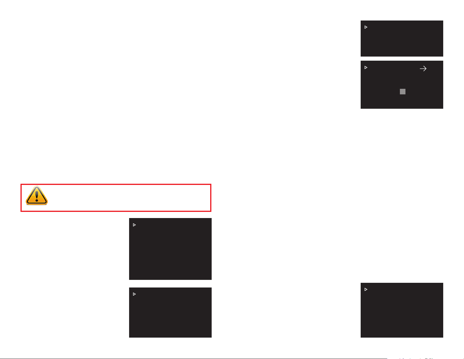
To mask off an area:
STEP 1. Exit the camera’s internal
menu use the controls to point the
camera at the area to be masked.
It should be in the center of the
PRIVACY NO :1
PRIVACY MASKING :OFF
SETTING
BACK EXIT
screen.
STEP 2. Return to the camera’s
internal menu and navigate back to
the Privacy Mask menu.
STEP 3. Move the cursor down to
Setting and click
the Iris + button to
RESIZE :
SAVE
BACK EXIT
open the configuration window.
STEP 4. A gray box will appear in
the middle of the screen. Clicking
the Iris + button while the cursor is
pointing to
Resize
. N
ote the arrow in the upper right corner. It will show which
way the box will expand. Clicking the left or right directional buttons will
change the direction of the arrow.
STEP 5. When you are satisfied with your mask, move the cursor to Save and
FUNCTION SETTING MENU
click the
Iris + button. Exiting this window without saving will not create a mask.
These settings replicate the control functions found on the DVR. Using this menu
to control your DVR is not recommended as it will create control conflicts with the
DVR. You will also not be able to make changes to these settings while remotely
monitoring your DVR - whether through a computer or mobile device.
PTZ Speed: Adjusts the speed of the PTZ from 1-5. The DVR’s PTZ controls will
override this.
Set Zero: This sets a “starting point” from which the azimuth coordinates are
measured from.
IMPORTANT! Do not use the camera’s internal menu to create tours
other actions as they will conflict with control of the camera through
the DVR. This conflict can cause the camera to freeze or damage it.
Power Up: By default, the camera will do a self-test of rotation and elevation
when it powers up. If you created a preset point, tour, scan, pan or pattern in the
camera’s internal menu, you can have the camera perform that function upon start
up. If their are multiple options, you can also choose which tour, etc. it will begin.
Menu Idle: You can adjust how long the internal menu will stay on-screen after a
There are two “pages” of menus (shown
on the right) with the first page covering
preset points, pan, scan, tour and pattern
operations.
The second page contains utilitarian
features that affect the operation of the
camera .
PRESET
PAN
AUTO SCAN
AUTO TOUR
AUTO PATTERN
IDLE MOTION
NEXT PAGE
BACK EXIT
period of inactivity.
PTZ Auto Stop: All PTZ operations will stop when there is no activity from within
the internal menu for a period of time. This is overridden by the DVR’s controls and
programming.
ALARM SETTING MENU
You can connect up to two external alarms, such as a motion sensor, to the
PTZ camera which can be set to perform any of the functions previously saved
through the internal menu. This is similar
Privacy Mask: This functions exactly like
the feature of the same name on the DVR
in that it creates an area on screen which
is blacked out. Unlike the DVR’s feature,
the privacy mask only appears when the
camera moves to view the area where the
mask was created. You can create up to
24 privacy masks.
PRIVACY MASK
PTZ SPEED
HORIZONTAL COORDINATES
POWER UP
MENU IDLE :1M
PTZ AUTO STOP :15S
BACK EXIT
to the alarm function on your DVR with
the exception that the DVR’s expanded
capabilities allow for greater flexibility and
control. It is recommended that alarms
should be connected to the DVR itself with
the desired actions programmed through
the DVR’s PTZ and alarm menus for this
reason.
ALARM NO :1
ACTION :NONE
PARAMETER :NONE
CONTACT :N/O
RELAY OUT :OFF
RESET DELAY :3S
SAVE
BACK EXIT
18 19
Page 11
CAUTION! Commands from the DVR can interfere with actions
programmed through the internal menu. This conflict can cause the
camera to freeze or damage it.
Alarm Number: Each alarm must have its own number. You can chose 1-7.
Action: This is the function you want to occur when an alarm is triggered. You can
have it move to a preset point, start a scan or tour.
Parameter: Specifies which point/scan/tour to perform.
Contact: Set for either N/O (normally open) or N/C (normally closed). Check your
alarm’s manual for which setting to use.
Relay Out: You can trigger another alarm or send an alarm notification to the DVR
as well as the reset time.
Reset Delay: Choose the length of time that the camera will operate in “alarm
mode” before returning to its normal state.
Save: If you do not save your settings by moving the cursor to Save and clicking
Iris + button. Exiting this window without saving will not create an alarm action.
the
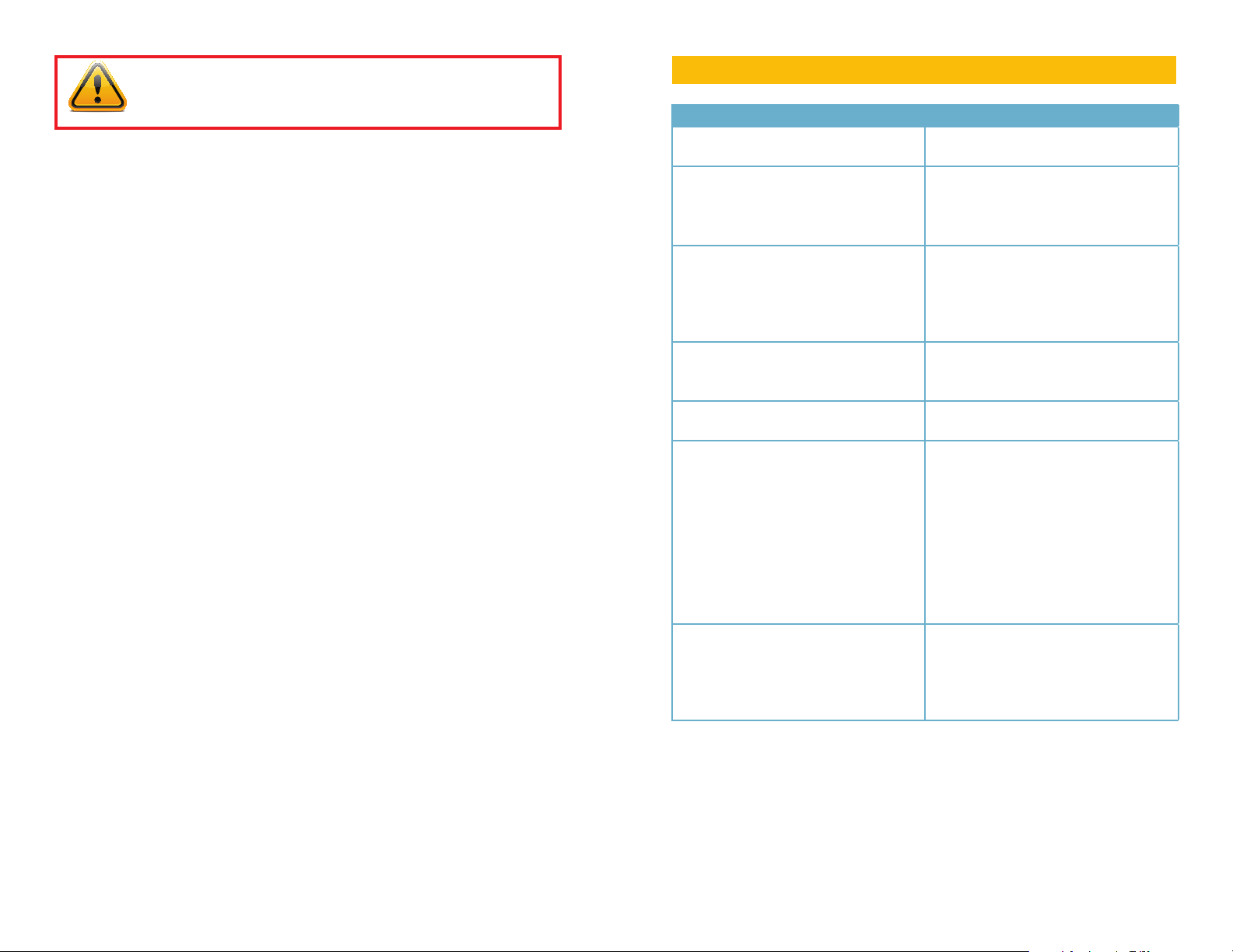
TROUBLESHOOTING
Problem Solution
No picture or unstable image Check both the power and video
connections to the camera.
The on-screen image is blurry. 1. Check for fingerprints or dirt on the
lens.
2. Check menu settings.
3. Check that auto-focus is enabled
The on-screen image is dim. 1. Check for fingerprints or dirt on the
lens.
2. Check monitor settings
3. Adjust exposure and shutter settings
in the internal menu.
The on-screen image is dark. 1. Adjust the monitor contrast settings.
2. Adjust exposure and shutter settings
in the internal menu.
The screen flickers. Camera may be facing sun, television or
computer monitor.
Camera is frozen. 1. Disable any actions programmed
through internal menu. (tours, scans,
etc.)
2. Power supply may need to be
located closer to camera.
3. Select Restart from internal System
Settings menu. (page 15)
4. Select Factory Default from the
internal System Settings menu. (page
15)
The camera is not working properly, is
hot, smells or is producing smoke.
DISCONNECT CAMERA FROM
POWER SUPPLY IMMEDIATELY!
1. Check that correct power supply is
in use.
2. Send camera out for repair.
20 21
Page 12

SPECIFICATIONS
Q-SEE PRODUCT WARRANTY
Specification
Camera Image Sensor 1/4” EXviewHAD CCD II
Eective Pixels NTSC: 976(H) × 494(V) PAL: 976(H) × 582(V)
Horizontal Resolution Color: 650TVL; B/W: 700TVL
Scanning System Interlacing
Electronic Shutter Speed 1/1s ~1/100,000s
Min. Illumination Color: 0.01 Lux/F1.6, B/W: 0.001Lux/F1.6
S/N Ratio More than 50dB
Video Output BNC(1.0Vp-p/75), PAL / NTSC
Camera
Features
Lens Focal Length 3.9 mm~89.7mm (23x Optical zoom)
PTZ PTZ Mode 5 Pattern, 8 Tour, 5 Auto Scan, Auto Pan
General Power Supply DC24V 3A
Day/Night Auto(ICR) / Color / B/W
Backlight Compensation BLC / HLC / DWDR (Digital WDR)
White Balance Auto, ATW, Indoor, Outdoor, Manual
Gain Control Auto / Manual
Noise Reduction 2D/3D
Privacy Masking Up to 24 Areas
Digital Zoom 16x
Max Aperture F1.6~ F3.7
Focus Control Auto / Manual
Angle of View 61.68° ~ 3.06°
Close Focus Distance 100mm~1000mm
Pan/Tilt Range Pan: 0° ~ 360° endless; Tilt: 0° ~ 90°, auto ip
180°
Manual Control Speed Pan: 0.1° ~ 250°/s; Tilt: 0.1° ~150°/s
Preset Speed Pan: 300°/s; Tilt:200°/s
Preset 80(DH-SD) , 255(Pelco-P/D)
Speed Setup Human-oriented focal length/ speed adaptation
Power up Action Auto restore to previous PTZ and lens status
after power failure
Idle Motion Activate Preset/Pan/Scan/Tour/Pattern if there is
no command in the specied period
Time Task Auto activation of Preset/Pan/Scan/Tour/Pattern
by preset-time
Protocol DH-SD, Pelco-P/D (Auto recognition)
Power Consumption 12W - 27W with heater on
Working Environment -40-140F (-40 - 60C) <90% Humidity
Protection Level IP66
Q-See is proud to back all of our products with a conditional service warranty
covering all hardware for 12 months from the date of purchase. Additionally, our
products also come with a free exchange policy that covers all manufacturing
defects for one month from the date of purchase. Permanent upgrading service is
provided for the software.
Liability Exclusions:
Any product malfunction or abnormalities in operation or damage caused by the
following reasons are not within the free service scope of our company:
1. Equipment damage caused by improper operation.
2. Improper equipment operation environment and conditions (e.g., improper
power, extreme environmental temperatures, humidity, lightning and sudden
surges of electricity).
3. Damage caused by acts of nature (e.g., earthquake, fire, etc).
4. Equipment damage caused by the maintenance of personnel not authorized
by Q-See.
5. Product sold over 12 months ago.
In order to fulfill the terms of your warranty, you must complete the registration
process after purchasing our product. To do this, simply fill out the User’s
Information Card on our website at www.Q-See.com
QUESTIONS OR COMMENTS? CONTACT US
24/7 TECHNICAL RESOURCES,
KNOWLEDGE BASE AND MORE
www.Q-See.com/Support
22 23
Page 13

Digital Peripheral Solutions, Inc.
8015 E. Crystal Drive
Anaheim, CA 92807
24
 Loading...