

QSC PLD4-3, PLD4-5, PLD4-2 Quick Start Manual
PLD Amplifier
Quick Start Guide
EXPLANATION OF TERMS AND SYMBOLS
The term “WARNING!” indicates instructions regarding personal safety. If the instructions are not followed the result may be bodily injury or death.
The term “CAUTION!” indicates instructions regarding possible damage to physical equipment. If these instructions are not followed, it may result in
damage to the equipment that may not be covered under the warranty.
The term “IMPORTANT!” indicates instructions or information that are vital to the successful completion of the procedure.
The term "NOTE" is used to indicate additional useful information.
The intent of the lightning fl ash with arrowhead symbol in a triangle is to alert the user to the presence of un-insulated "dangerous"
voltage within the product's enclosure that may be of suffi cient magnitude to constitute a risk of electric shock to humans.
The intent of the exclamation point within an equilateral triangle is to alert the user to the presence of important safety, and operating
and maintenance instructions in this manual.
NOTE:
four separate outputs. For detailed instructions for custom confi gurations refer to the PLD User Guide (TD-000368).
This Quick Start Guide is based on the basic confi guration as the amplifi er comes from the factory. Four separate inputs, and
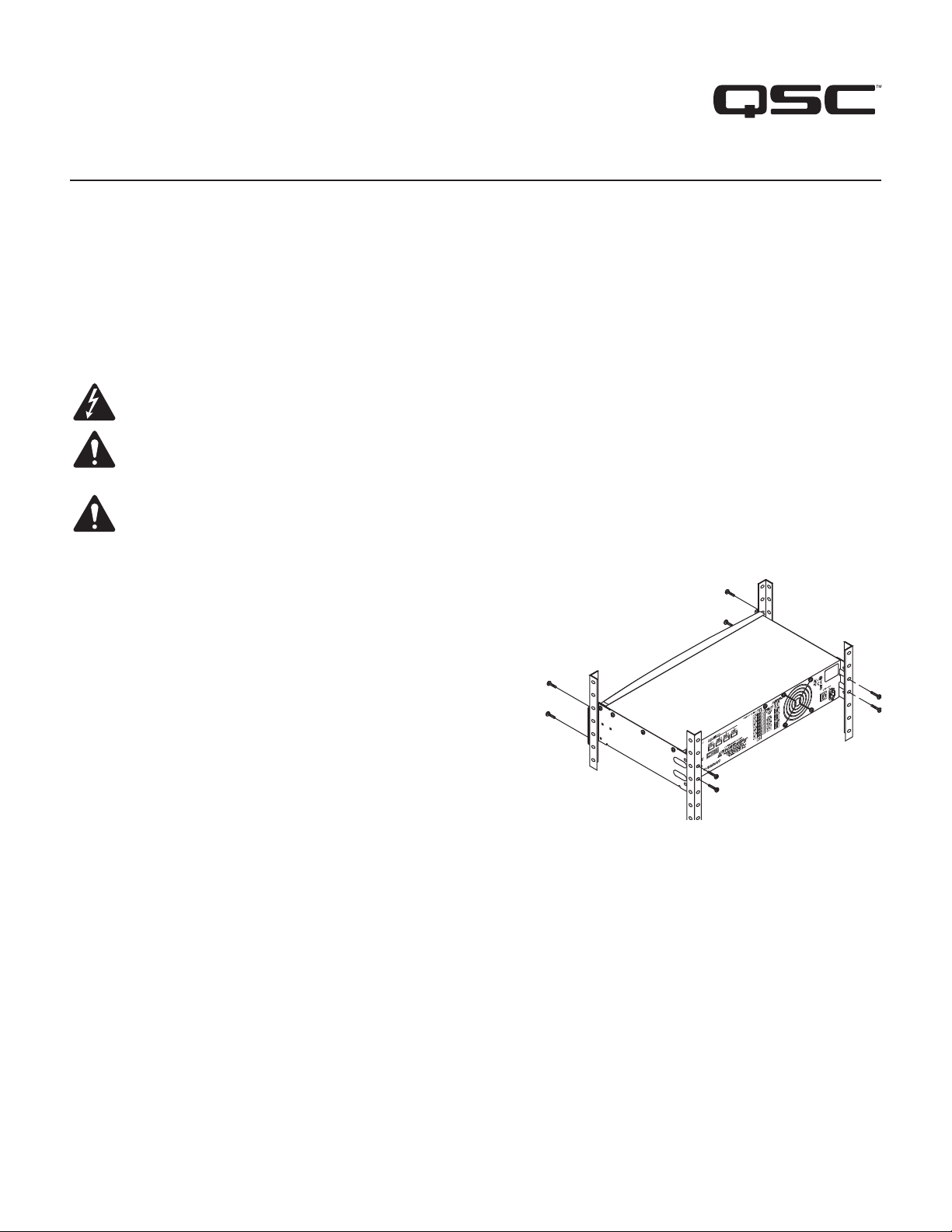
Rack-Mount the Amplifi er
1. Secure the amplifi er in the rack with eight screws (not supplied), four in front,
four in back.
— Figure 1 —
TD-000351-00-B
*TD-000351-00*
1
Connections
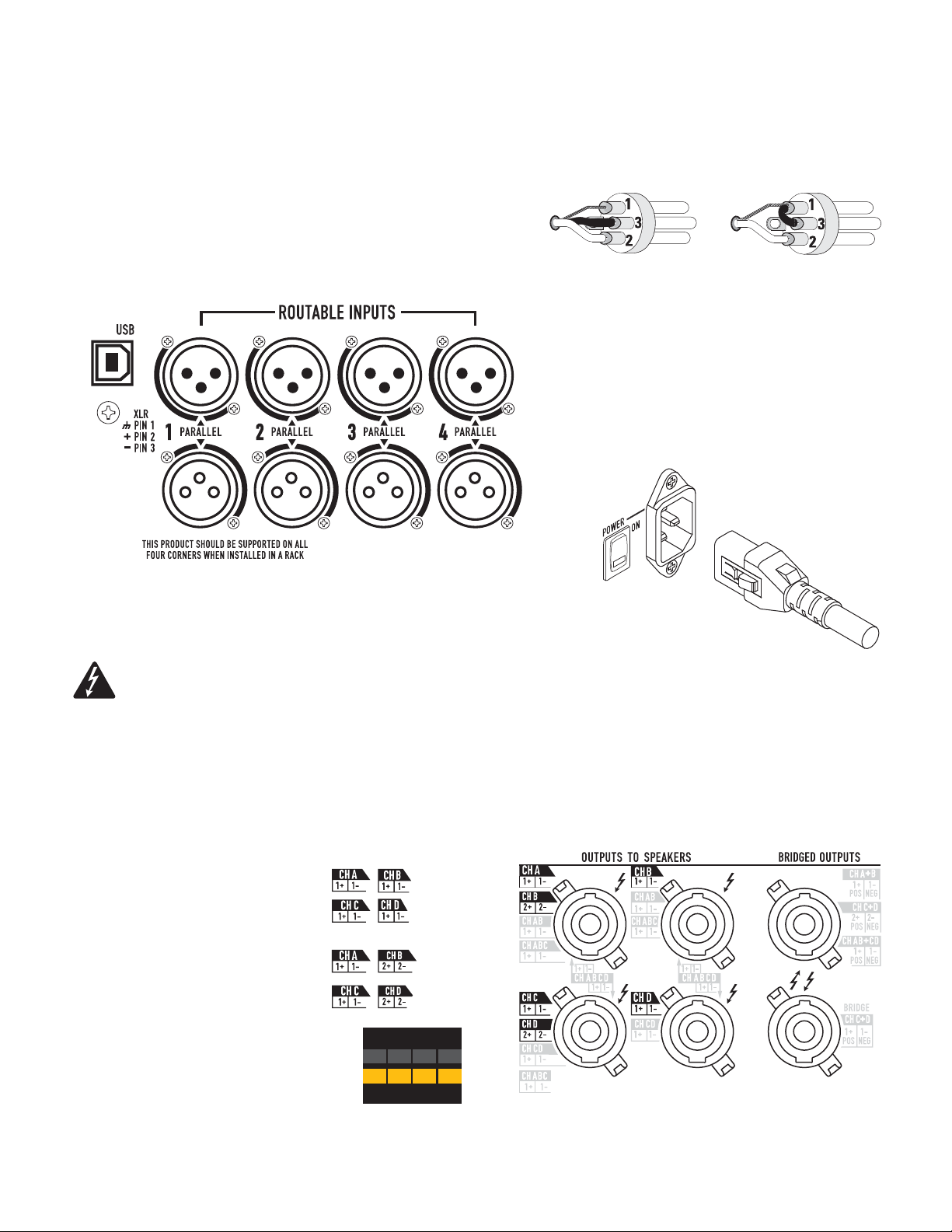
Inputs
1. Wire the audio line-level source to four male XLR connectors. You may use either
balanced inputs (Figure 2) or unbalanced inputs (Figure 3).
2. Plug the male XLR connectors into the appropriate receptacles (Routable Inputs 1,
2, 3, 4) Figure 4. If you are daisy-chaining inputs with another amplifi er, plug the
female XLR connectors, from the other amplifi er, into the XLR's on the bottom row
of the Routable Inputs.
— Figure 2 —
— Figure 3 —
— Figure 4 —
3. Connect the IEC power cord to the AC receptacle on the rear of the amplifi er. (Figure 5)
WARNING!:
Do not turn the amplifi er on at this time.
— Figure 5 —
Outputs
When the output confi guration of the amplifi er changes, the Outputs to the loudspeakers change accordingly. Connect the loudspeakers to the NL4
twist-lock connectors as shown in Figure 6 thru Figure 8. After connecting the Outputs to the Loudspeakers, you may turn the amplifi er on.
Separate Channels (A B C D)
For Four Separate Cables
Use four 2-wire cables, connect to:
• 1+/1- on connectors #1 thru #4
For Bi-amp Operation
Use two 4-wire cables, connect to:
• 1+/1- for CH A and 2+/2- for CH B
on connector #1
• 1+/1- for CH C and 2+/2- for CH D
on connector #3
A
8.0
625
625
B
8.0
625
625
C
8.0
625
625
D
8.0
625
625
1
3
2
4
5
6
— Figure 6 —
2
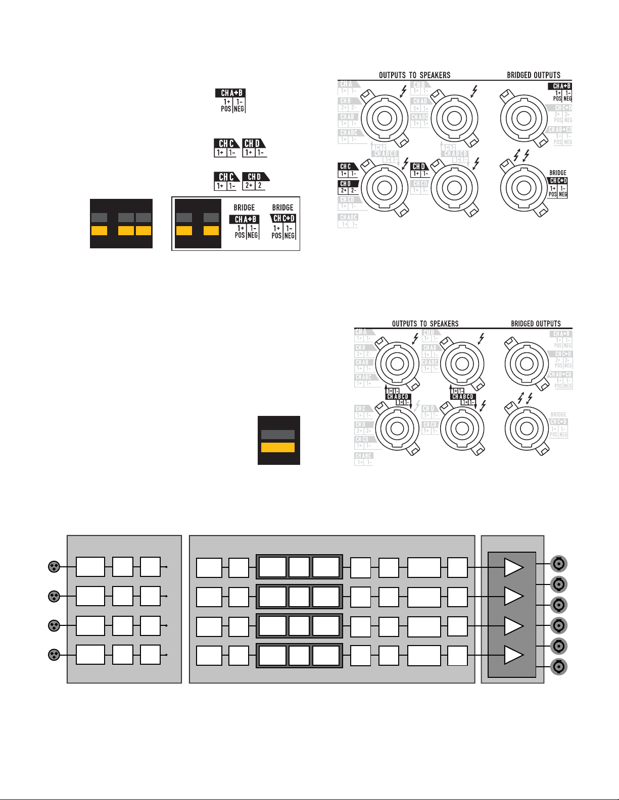
Bridged (A+B) and Separate (C D ) Channels
For A+B (Bridged)
Use one 2-wire cable connect to:
• 1+/1- on connector #5
For C & D (Separate)
Use two 2-wire cables connect to:
• 1+/1- for CH C on connector #3
•1+/1- for CH D on connector #4
Bi-amp operation, use one 4-wire cable connect to:
• 1+/1- for CH C on connector #3
• 2+/2- for CH D on connector #3
A+B
1250
1250
8.0
8.0
625
625
C
D
8.0
625
625
A+B
8.0
1250
1250
C+D
8.0
1250
1250
Parallel Channels (ABCD)
For Multiple Loudspeakers
Full power for multiple loudspeakers in parallel
Use up to four 2-wire cables, connect to:
• 1+/1- on connectors #1 thru #4
For One Loudspeaker
Full power to one loudspeaker
Use one 2-wire cable, connect to:
• 1+/1- on connector #1, #2, 3#, or #4
— Figure 7 —
A B C D
8.0
2500
2500
1
3
1
3
2
4
2
4
5
6
5
6
PLD Amplifi er Signal Flow
Input Settings
Sensitivity
Switch
Sensitivity
Switch
Sensitivity
Switch
Sensitivity
Switch
Meter
Meter
Meter
Meter
Gain
Gain
Gain
Gain
1
2
3
4
Source
Select
Source
Select
Source
Select
Source
Select
Mute
Mute
Mute
Mute
Button
Actuated
Highpass
Filter
Highpass
Filter
Highpass
Filter
Highpass
Filter
— Figure 8 —
Output Processing
Lowpass
Gain /
Filter
Polarity
Lowpass
Gain /
Filter
Polarity
Gain /
Lowpass
Polarity
Filter
Gain /
Lowpass
Polarity
Filter
Crossover
— Figure 9 —
5-band
PEQ
5-band
PEQ
5-band
PEQ
5-band
PEQ
Delay
Delay
Delay
Delay
RMS / Peak
Limiter
RMS / Peak
Limiter
RMS / Peak
Limiter
RMS / Peak
Limiter
Meter
Meter
Meter
Meter
Amp Configuration
A
B
C
D
Set by Wizard
3
 Loading...