

Page 1
MF 70 cnc-ready
Manual
Page 2
4
8
7
3
5
11
6
9
1210
2
1
-4-
Fig. 1a
7
1
6
8
2
3
45
Fig. 1b
abc
M4 x15M4x40 M4 x15
Fig. 2
Fig. 3
Page 3
2
4
3
1
2
1
-5-
1
3
2
1
4
3
2
2
5
Fig. 6
Fig. 4
Fig. 5
Fig. 8
Fig. 7
Page 4

-10-
Translation of the Original Operating
Instructions Micro miller MF 70 CNCreadyand compound table KT 70 CNCready
Dear customer!
Regardless of whether you have purchased aMicro miller
MF 70 CNC-ready or the compoundtableKT70CNCready, you have carefullydesigned and manufactured
equipment for all fine, precision milling operationsinvolving
metal, plastics or wood at your disposal.
Designed on the basis of our proven Micro miller MF 70
and compoundtableKT70models, the CNC-readyversions
of both products offer the same features in each case, but
are fitted with stepping motors instead of the familiar
handwheels.
These take charge of traversing of the compoundtable
carriageand the milling headduring milling operations.
ACNC controlsystem (not included in the scope of
delivery) is responsible forsupplying the stepping motors,
thus enabling traversing in all three axes.
Thecolumn and compoundtableconsistofhigh-precision,
surface-compacted aluminiumand areequipped with
adjustabledovetail guides whichare free of play.The
stable basis of the Micro millerMF70CNC-ready is providedbyaheavy machine base made of greycast iron.
An extremely low-vibration,carefully balanced 24-pole
high-performance DC motor ensures thatthe Micro miller
MF 70 CNC-ready exhibits quiet and uniform running characteristics,and electronic controlateveryspeedfrom
5000 to 20000revolutionsper minute provides adequate
power whichenablesaccurate machining with even the
smallest milling cutter diameters!
The clamping jawset included ensures thatthe workpieces
to be machined aresecured safelyand reliably.
In addition, the scope of deliveryofthe millerincludes a
colletset with sixclamping jaws with apractical selection
of diameters of 1.0 -1.5 -2.0 -2.4 -3.0 and 3.2 mm held
in an orderlyfashion in acollet block. Carefullyselected
material and targeted hardening contribute to along
servicelife,while the triple slotting ensures maximum precision.
Our comprehensiveand carefully compiled accessory
range providesyou with alarge selection of machining
tools of everykind. These can be found in our equipment
brochure or on the internetatwww.proxxon.com.
We are confident thatyou will be impressed by the successfulmachiningresults achieved and we hopeyou enjoy
using our compound table KT 70 CNC-ready or the
completemiller MF 70 CNC-ready!
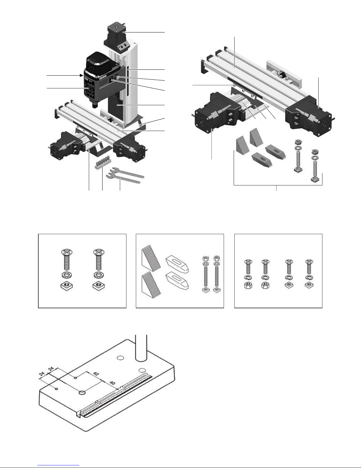
1 Micro miller MF 70 CNC-ready(Article 2712,
Fig. 1a):
1.1 Key to general view
1. On/Off switch
2. Speed controlknob
3. Scale forZ-axis
4. Motor for Z-axisspindle drive
5. Spindle cover
6. Compound table KT 70 CNC-ready
7. Adjusting screws
8. Table forspindle speeds
9. Collets
10. Machine base
11. Hole forbase fixing
12.Wrenches
1.2 Technicaldata:
Miller
Voltage: 230 Volt, 50/60 Hz
Capacity: 100 Watt
Spindle speed 5,000 –20,000/min
Overall height (approx.): 400 mm
Z-axis traversing path (approx.): 70 mm
Mass: 7kg
Noise generation70dB(A)
Vibration 2.5 m/s2
Please notethatthe sound and vibration measurementsin
particularhavebeen performed with Proxxon bits and cutters. When usingthird-party brands we cannotguarantee
compliance with the statements givenhere!
1.3 Scope of delivery:
•Miller spindle with Z-column and robust base,stepping
motor and connectingcable
•Compound tableKT70CNC-ready with stepping
motors, mounting parts and connecting cable
•
Colletblock (colletØ1.0, 1.5,2.0, 2.4,3.0 and 3.2 mm)
•Operating tools
•Operating and safetyinstructions
2 Compound table KT 70 CNC-ready
(Article 27114, Fig. 1b):
2.1 Key to general view
1. T-slot table
2. X-axis drivemotor
3. Baseplate
4. Support
6. Y-axis drive motor
7. Adjustingscrews
8. Clamping jawset incl.mountingparts
GB
Page 5

-11-
2.2 Compoundtable KT 70 CNC-ready (Fig. 1b):
Table size 250 x70mm
Traversing paths (approx.):
X-axis 150mm
Y-axis 70 mm
T-slot dimensions 12 x6x5mm
T-slot spacing 25 mm
Mass: 2kg
2.3 Scope of delivery:
•Compound tableKT70CNC-ready with stepping
motors and connecting cable
•Mountingparts
Fig. 2a Screws/nutsfor clamping the machinevice MS
4
Fig. 2b Clamping jaws
Fig. 2c Mounting parts forfixing the coordinate table
•Flexible spiralhose
•Operating and safetyinstructions
Use only in dryrooms
Pleasedonot dispose of thiselectrical
machine in the household waste!
Foryour safety,always wear hearing
protection whileworking!
3 Mounting the Micro coordinate table KT 70
CNC-readyonthe PROXXON drill stand MB
200, MB 140 or PROXXON table drilling
machine TBM 220 (Fig. 3)
TheMicro coordinate table KT 70 CNC-ready is ideally suitable foruse in combinationwith the PROXXON drill stand
MB 200, the MB 140 or the PROXXON table drilling
machine TBM 220. It is, forexample, perfectfor semi-automatic coordinatedrilling!
Aconventional MF 70 can alsoberetrofitted with this
device, althoughautomatic operationofthe Z-axis is then,
naturally enough, no longeranoptioninthis configuration.
The existing compound table can be simply replacedfor
thispurpose. TwoM4threads should first be cut in the
worktop as depicted in Fig. 3for usewith the PROXXON
drill stand or the PROXXON table drilling machine TBM 220.
1. Pilotdrillthe threaded holeswith adrillbit (ø 3.3 mm)
and countersink the holes. Then cut the threads with
an M4 tap.
2. The Micro coordinate table KT 70 CNC-ready can now
be fixed to the drill stand base with the aid of the M4
threaded holesand the mounting parts providedwith
the device.
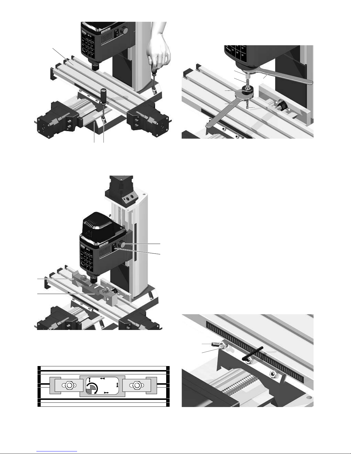
4 Miller setup (Fig. 4):
Caution:
Pleaseensure thatthe mains plug is pulled out of the
socket during all assembly,setup or adjustingwork! A
failure to do thismay result in the inadvertentstartingof
the machine, damage and injury.
Caution:
Themiller should be screwed securely to astablesupporting surface foroperation! Four holesare provided in the
device basefor thispurpose with which the millercan be
screwed to an appropriate supporting surface using suitable
bolts(3)!
The compound table (Fig. 4) can thenbefixedtothe base
using the 4M4Allen screws provided. The compound table
carriage mayneed to be traversed for thispurpose in order
to move the carriage and worktabletoensure access to
the screwholes.
Caution: No control system shouldbeconnected to the
machineifthe spindles arerotated manuallytotraverse
the carriage!
Following connectionofthe plug connectors to the control
system,the wiring should be sheathedinthe spiralhose
provided.
5 Fitting the collets (Fig. 5):
Caution:
Pullout the mains plug priortoany adjusting, setupor
assemblywork, as there is otherwisearisk of injuryor
possible damagetothe device!
Alwaysinsertasuitable tool in the collettotightenthe
union nut! Tightening the union nut without an appropriate
shaftwill damagethe collet!
All operational tools should be clamped as short as
possible! Shafts protruding too far will vibrate and result in
poor milling results.
1. Hold the spindle1firmly on the flats with one of the
wrenches 2provided and releaseand remove the
union nut 3.
2. Insertthe desired collet4into the spindle and tighten
the union nut 3slightly by hand.
3. Insertthe desired tool 5into the collet. Caution:
Ensure thatthe tool shaftdiameter corresponds to the
inside diameter of the collet!
4. Hold the spindle firmly with the wrench and tighten
the union nut firmly with the second wrench.
Page 6

-12-
6 Selecting the spindle speed
Themiller is equippedwith an electronic speedcontrol
system. This enables the continuousadjustment of the
spindle speedwithin arangefrom 5000-20000rpm to suit
different materials, tool feed speeds, infeeds and milling
cutter diameters. Optimum adaptationofthe milling parameters is therefore possible to suit all operating conditions
encounteredunder practicalcircumstances.
Fundamentally speaking, the following apply:
Higherspeeds Smallermilling cutter diameters
High feed
High infeed
Lower speeds Greatermilling cutter diameters
Lower feed
Reducedinfeed
The table on the front of the millerprovides assistance
when selecting the right spindlespeed.
7 Working with the miller (Fig. 6)
Caution:
Wear protective goggles when milling.Itisimperative that
the safety instructions included be observed!
TheMicro millerMF70CNC-ready and compoundtableKT
70 CNC-ready weredesigned for fine, precision work.
Decisive milling parameters such as infeed or feed should
therefore be adapted in the software you are using.
Pleasenote that, in addition to negatively influencing the
working results, mechanicalorelectricaloverloadingofthe
machinealso strikingly increasesmachinewear,particularly
on the drive, bearingsand guides.
1. The workpiece 1should be fixed reliably and safely
using either the clamping jaws 2provided or another
appropriate clamping medium.
2. Realisethe milling process. Ensure thatthe switch 3is
in the “On” position. The motorshould be activated
manually if the CNC controlsystem does not support
automatic activation and deactivation of the spindle
drive.
3. Set the appropriate speedwith the knob4ifnecessary.
4. Ensure thatthe feed speedand infeed depthare
appropriate!The milling cutter should operate during
counter rotationasillustrated in the diagram in Fig. 7.
This means thatthe motionofthe milling cutter
cutting edge should alwaysbecounter to the feed
direction!
8 Maintenance and care
Thedeviceismaintenance-free, apart from the necessity
for regular cleaning and,whererequired,readjustment and
lubrication of the guides. Thetasks necessaryinthis
respect aredescribed below.
8.1 Adjustmentofplay in the dovetail guides (Fig. 8)
Caution:
Pullout the millermainsplug priortoany adjusting, setup
or assemblywork, as there is otherwisearisk of injuryor
possible damagetothe device!
Boththe millerand the compound table areequipped with
adjustable dovetail guides. These provide an option for
counteracting mechanicalwear whichoccurs naturally
when working with the millerorcompound table. The
guides can be readjusted simplyifthe play becomestoo
greatafter asufficiently long period of use. Please note
thatthe procedurefor the miller and compoundtableisthe
same.
1. Loosenthe hexagonal nuts 1.
2. Screw in the setscrews2slightly with asuitable Allen
key. The setting is correct if play is minimal, but the
guide still works smoothly.
Please note:
Excessive tightening of the setscrews results in increased
wearand maydamage the guide!
3. Following successful adjustment, hold the setscrews
in the correct position with an Allenkey and counter
lockbytightening the hexagonal nuts.
Accessories
Formore detailed information on accessories,please
request our device catalogue from the address specified on
the last page in the warranty information.
Please noteingeneral:
Proxxonbits and cuttershavebeen designed to work with
our machines, whichmakes them optimal for theiruse.
We will not assumeany liabilitywhatsoever forthe safe
and proper function of our devices when using third-party
bits and cutters!
8.2 Cleaning
Caution:
Alwayspull out the millermainsplug priortomaintenance,
cleaning and repairs. Inadvertentactivation mayresult in
injury!
Page 7

-13-
To ensure along servicelife,the machine should be
cleaned with asoft cloth, handbrushorpaintbrush after
each use. Useofavacuum cleaner is alsorecommended
here.
Theoutside of the housing can thenbecleaned with asoft
cloth, dampened if necessary. It is possible to use mild
soaporanother suitable cleaning agent. Solvents or cleaning agents containingalcohol(e.g. petrol,cleaning alcohols,
etc.) shouldbeavoided, sincethese can attack the plastic
parts.
It is besttoapply adrop of machineoil to moving parts
occasionally.The milling headguides and compound table
should be lubricatedatregular intervals.
8.3 Repairs:
Caution:
Always pull out the mainsplug beforemaintenance, cleaningand repairs. Inadvertent activationmay result in injury!
Repairs should only be realisedbyqualified skilledpersonnel or,better still,bythe PROXXON CentralService! Never
repairelectricalparts, butalways replace them with
original PROXXON spare parts!
9 Disposal
Pleasedonot dispose of thismachineinhouseholdwaste!
Thedevicecontains valuablematerialswhich can be recycled. If you have anyquestions in this respect,please contact your localdisposalcompanyorother relevantcommunal facilities.
10 EC Declaration of Conformity
Name and address:
PROXXON S.A.
6-10, Härebierg
L-6868 Wecker
Product designation: MF 70 CNC-ready
Article No.: 27112
We hereby declareonour sole responsibilitythatthis
product conforms to the following directives and normativedocuments:
EU EMC Directive 2014/30/EC
DINEN55014-1/05.2012
DIN EN 55014-2/02.2016
DIN EN 61000-3-2/03.2015
DIN EN 61000-3-3/03.2014
EU MachineryDirective 2006/42/EC
DINEN61029-1 /01.2010
Date:31.08.2016
Dipl.-Ing. JörgWagner
PROXXON S.A.
Appliance Safety Division
The CE document authorizedagent is identical to the
signatory.
Page 8

-54-
Page 9

MF 70 cnc-ready
-55-
Page 10

-56-
Page 11

27114 - 01 Work table
27114 - 02 Support
27114 - 03 Base plate
27114 - 04 Nut
27114 - 06 Holding plate
27114 - 07 Limit stop, cpl.
27114 - 08 Screw
27114 - 09 Coupling
27114 - 10 Screw
27114 - 11 Holder for Motor
27114 - 12 Screw
27114 - 13 Step motor
27114 - 14 Screw
27114 - 15 Nut
27114 - 16 Holding plate for
bearing y-axle
27114 - 17 Rolling bearing
ET-Nr.: Description ET-Nr.: Description
27114 18 Screw
27114 19 Screw
27114 - 20 Nut
27114 - 21 Y spindle
27114 - 22a Spindle nut
27114 - 22b Spindle nut
27114 - 23 Holder plate
27114 - 24 Holding plate for
bearing x-axle
27114 - 25 x spindle
27114 - 26 Adjustment plate
27114 - 27 Nut
27114 - 28 Set screw
27114 - 29 Adjustment plate
27114 - 30 Terminal
27114 - 31 Wiring
KT 70 CNC-ready
-57-
Page 12

12 Motors and Wiring:
12.1 Technicaldata of the Motors:
Type Bipolar-Type
Current 1,8 A/Phase
Holdingtorque0,5 Nm
Step angle 1,8°
Mass0,34 kg
Rotor inertia 66,5 gcm2
Resistance/Phase 1,75Ohm
Inductance/Phase 3,3 mH
12.2 Pin-Content oft theSubD-Plug
Endswitch
Coil 1a
Coil 1b
Coil 2a
Coil 2b
12.3 Colour of wires axle-specificwiring oft the
motors:
SubD-Pin MotorColour
of wire
1Coil 1a black
2Coil 1b browne
4Coil 2a red
5Coil 2b orange
7End switch black
8End switch browne
Directionoft rotoa-
tion oft spindle
whiledriving in
positive Direction
Flanklead
Pin-Content in the Molex-Plug:
12 3456
xbrowne black orange redCWRH
ybrowne black redorangeCCW LH
z browne black orange redCWLH
Axle
-58-
Page 13

GB Service note
All PROXXON products are thoroughly inspected after production. Should a defect
occur nevertheless, please contact the dealer from whom you purchased the
product. Only the dealer is responsible for handling all legal warranty claims
which refer exclusively to material and manufacturer error.
Improper use, such as capacity overload, damage due to outside influences
and normal wear are excluded from the warranty.
Youwill find further notes regarding "Service and Spare Parts Management" at
www.proxxon.com.
Art.-Nr.27112-99 PR 7087167005 J
 Loading...