


 Loading...
TRAK® LPM
Programming, Safety, and Operating Manual
Document: 26728
Version: 051013
Southwestern Industries, Inc.
2615 Homestead Place
Rancho Dominguez, CA 90220-5610 USA
T | 310-608-4422 |F | 310-764-2668
Service Department: 800.367.3165
e-mail: sales@southwesternindustries.com | service@southwesternindustries.com | web: southwesternindustries.com
Copyright 2013, Southwestern Industries, Inc. All rights are reserved. No part of this publication may be reproduced, stored in a retrieval system, or transmitted, in any form or by any means, mechanical, photocopying, recording or otherwise, without the prior written permission of Southwestern Industries, Inc.
While every effort has been made to include all the information required for the purposes of this guide, Southwestern Industries, Inc. assumes no responsibility for inaccuracies or omission and accepts no liability for damages resulting from the use of the information contained in this guide.
All brand names and products are trademarks or registered trademarks of their respective holders.

Table of Contents
1.0Introduction
1.1 Manual Organization 1
2.0 |
Safety |
|
2.1 |
Safety Publications |
3 |
2.2Danger, Warning, Caution and Note Labels and Notices Used in this Manual
2.3Safety Precautions
3.0 |
Description |
10 |
3.1Control Specification
3.1.1ProtoTRAK PMX Hardware Specifications
3.1.2ProtoTRAK PMX Software Specifications
3.1.3ProtoTRAK PMX Control Options
3.1.4DXF File Converter Option
3.1.5CAM Out Option
3.1.6How to Buy Software Options
3.2Display Pendant
3.2.1Program Panel
3.2.2Run Panel
3.2.3Pendant Right Side
3.3Machine Description
3.3.1Overall Machine Dimensions
3.3.2Machine Specifications
3.3.3Maximum Spindle Torque and Horsepower
3.3.4Electrical Cabinet
3.3.5Computer Module
3.3.6Servo Motors
3.3.7Servo Drives
3.3.8Spindle
3.3.9Spindle Motor & Drive
3.3.10Automatic Draw Bar Assembly
3.3.11Retention Knobs
3.3.12Tool Changer
3.3.13Drive Train, Axes
3.3.14Worktable
3.3.15Limit/Home Switches
3.3.16Lubrication System
3.3.17Coolant and Coolant Wash System
3.3.18Pneumatic System
3.3.19Enclosure Doors
3.3.20Beacon Lights
3.3.21Chip Removal System
3.3.22Work Lamps
4.0 |
Basic Operation |
27 |
4.1Machine and Control Power On
4.2Control and Power Off
4.2.1Energizing the Servos
4.2.2Homing the Machine
4.2.3Warming Up the Machine
4.2.4Current and Staged Control Views
4.3Spindle Operation
4.4Electronic Handwheel
4.4.1Manual Axis Movement
4.4.2Feed Override
4.4.3Spindle Override
4.5Multiple Uses of the GO Button
4.6Multiple Uses of the STOP Button
4.7Emergency Stop
4.8Enclosure
4.8.1Front Door
4.8.2Side Doors
4.8.3Positioning the Control Panel
4.9Coolant
4.9.1Coolant ON/OFF
4.9.2Coolant Wash
4.9.3Coolant Hose
4.9.4Checking Coolant Levels
4.10Air
4.10.1Air Hose
4.10.2Air Blast
4.10.3Checking Air Pressure
4.11Chip Removal
4.11.1Auger Operation
4.12ATC Operation
4.12.1Advancing the Carousel
4.12.2Manual Tool Load and Unload
4.13Lubrication
4.14Help Functions
4.14.1Math Helps
5.0 |
Definitions, Terms & Concepts |
34 |
5.1ProtoTRAK PMX CNC Axis Conventions
5.2Part Geometry and Tool Path Programming
5.3Planes and Vertical Planes
5.4Absolute and Incremental Reference
5.5Referenced and Non-Referenced Data
5.6Incremental Reference Position in Programming
5.7Tool Diameter Compensation
5.8Tool Diameter Compensation When Contouring in Z with Part Geometry
5.9Connective Events
5.10Conrad
5.11Memory and Storage
5.12Current and Staged Views
6.0 DRO Mode |
42 |
6.1Entering Dimensions
6.2Reference Locations
6.3Power Feed
6.4GO TO
6.5Return to Absolute Zero
6.6Spindle Operation
6.7Axis Motion in the DRO Mode
i
Southwestern Industries, Inc.
TRAK 2OP Installation, Maintenance, Service & Part List Manual

7.0 |
Program Mode Part 1: Getting |
46 |
9.4 |
Skipping Over Prompts |
|
Started & General Information |
|
9.5 |
The OK/NOT OK Flag |
7.1 |
Programming Overview |
|
9.6 |
Ending A.G.E. |
7.2 |
Enter Program Mode |
|
9.7 |
Guessing Data |
7.3 |
Program Header Screen |
|
9.8 |
LOOK and Guess |
7.3.1 |
Program Name |
|
9.9 |
Calculated Data |
7.3.2 |
General Program Options |
|
9.10 |
Arcs and Conrads |
7.3.3 |
Program Header Softkeys |
|
9.11 |
Tangency |
7.4Assumed Inputs
7.5 |
Z Rapid Positioning |
|
10.0 |
Edit Mode |
86 |
7.6 |
Softkeys within Events |
|
10.1 |
Delete Events |
|
7.7 |
Programming Events |
|
10.2 |
Spreadsheet Editing |
|
7.8 |
Editing Data While Programming |
|
10.2.1 |
Selecting Data to be displayed on the Search Edit Table |
|
7.9 |
LOOK |
|
10.2.2 |
Sorting Data |
|
|
|
|
10.2.3 |
Making Global Changes to Data |
|
8.0 |
Program Mode Part 2: |
54 |
10.3 |
Erase Program |
|
|
Program Events |
|
10.4 |
Clipboard |
|
8.1 |
POSN: Position Events |
|
10.5 |
G-Code Editor |
|
8.2 |
DRILL Events |
|
10.6 |
Update GCD |
|
8.3 |
BOLT HOLE Events |
|
10.7 |
Next Program |
|
8.4MILL Events
8.5 |
ARC Events |
11.0 |
Program Set Up Mode |
98 |
8.6 |
POCKET Events |
11.1 |
Part / Fixture Management |
|
8.6.1 |
Circular Pocket |
11.1.1 |
PICTURE |
|
8.6.2 |
Rectangular Pocket |
11.1.2 |
NOTES |
|
8.6.3 |
Irregular Pocket |
11.1.3 |
GO TO |
|
8.6.4 |
Tool Path in Pocket Events |
11.1.4 |
Z SAFETY |
|
8.6.5 |
Zigzag Z Depth Cuts |
11.1.5 |
Part/Fixture Management LOOK |
|
8.6.6 |
Conrad in Pocket Events |
11.2 |
Tool Management |
|
8.6.7 |
Bottom Finish Cut |
11.2.1 |
TOOL CRIB |
|
8.6.8 |
Face Mill Event |
11.2.2 |
REMOVE TOOL |
|
8.7 |
ISLAND Events |
11.2.3 |
NOTES |
|
8.7.1 |
Circular Island |
11.2.4 |
DISABLE LOC |
|
8.7.2 |
Rectangular Island |
11.3 |
TOOL PATH |
|
8.7.3 |
Irregular Island |
11.3.1 |
Softkeys in Tool Path |
|
8.8 |
PROFILE Events |
11.4 |
Run Strategy |
|
8.8.1 |
Circle Profile |
11.5 |
Tool Recon (Reconciliation) |
|
8.8.2 |
Rectangular Profile |
|
|
|
8.8.3 |
Irregular Profile |
12.0 |
Machine Set Up Mode |
114 |
8.9 |
HELIX Events |
12.1 |
Tool Loading |
|
8.10 |
Subroutine Events |
12.1.1 |
Tool Status Box |
|
8.10.1 |
REPEAT |
12.1.2 |
Tool Loading Table |
|
8.10.2 |
MIRROR |
12.1.3 |
REMOVE TOOL |
|
8.10.3 |
ROTATE Z Axis |
12.1.4 |
ADD TOOL |
|
8.11 |
COPY Events |
12.1.5 |
CALL TOOL |
|
8.11.1 |
Copy Drill to Tap |
12.1.6 |
RETURN TOOL |
|
8.12 |
THREAD MILL Event |
12.1.7 |
RESET ATC |
|
8.13 |
PAUSE Events |
12.2 |
Checklist |
|
8.14 |
TAP Events |
12.3 |
Service Codes |
|
8.14.1Tapping Notes & Recommendations
8.15 |
ENGRAVE Event |
|
13.0 |
Run Mode |
122 |
8.16 |
Auxiliary (AUX) Functions Event |
|
13.1 |
Run Mode Screen |
|
|
|
|
13.2 |
Starting to Run |
|
9.0 |
Program Mode Part 3: |
79 |
13.2.1 |
Starting to Run – Single Program |
|
|
The Auto Geometry Engine (A.G.E) |
|
13.2.2 |
Starting to Run – Master Program |
|
|
Programming |
|
13.3 |
Program Run |
|
9.1 |
Starting the A.G.E. |
|
13.4 |
TRAKING |
|
9.2 |
A.G.E. Mill Prompts |
|
13.5 |
Program Run Messages |
|
9.3 |
A.G.E. Arc Prompts |
|
13.6 |
STOP |
|
ii
Southwestern Industries, Inc.
TRAK 2OP Installation, Maintenance, Service & Part List Manual

13.7 |
Feedrate and Speed Overrides |
|
15.4.1 |
POSN |
13.8 |
Data Errors |
|
15.4.2 |
MILL 4 AXIS |
|
|
|
15.4.3 |
ENGRAVE 4 AXIS |
|
|
|
15.4.4 |
AUX Event |
14.0 |
Program In/Out Mode |
126 |
15.4.5 |
LOOK |
14.0.1 |
Filenames and File Extensions |
|
15.5 |
PROG SETUP Modes |
14.1 |
Softkey Selections in the Program In/Out Mode |
15.5.1 |
PART/FIX MGMT Screen |
|
14.2 |
Basic Navigation of Program In/Out Mode Screens |
15.5.2 |
Tool Path |
|
14.2.1 |
Basic Parts of the Program In/Out Mode Screens |
15.6 |
MACHINE SETUP Mode |
|
14.2.2 |
Softkeys in the Program In/Out Mode Screens |
15.6.1 |
SERV CODES Screen |
|
14.3 |
Opening a File |
|
15.6.2 |
4th AXIS ON / OFF |
14.3.1 |
Creating a Master Program |
|
15.7 |
PROG I/O |
14.3.2 |
Preview Graphics |
|
15.7.1 |
4th Axis G-Code notes |
14.4 |
Saving Programs |
|
15.8 |
4th Axis Setup Notes |
14.5Copying Programs
14.6Deleting Programs
14.7Renaming
14.8Backing Up
14.9Converters™
14.9.1Activating Converters
14.9.2Converting From a Different Format into a ProtoTRAK PMX CNC
14.9.3Converting From the ProtoTRAK PMX CNC to a Different Format
14.10ProtoTRAK and TRAK CNC Compatibility 14.10.1 File Formats
14.10.2 Opening .MX3 and .PT4 files on a ProtoTRAK PMX CNC
14.10.3 Running ProtoTRAK PMX Files on ProtoTRAK and TRAK CNC Controls
14.11Running G Code Files (GCD)
14.11.1G Codes Recognized by the ProtoTRAK PMX GCD Converter
14.11.2M Codes Supported by the ProtoTRAK PMX CNC
14.11.3Valid Characters for Word/Address Sequences
14.12Networking
14.12.1A Basic Peer-To-Peer Network
14.12.2Assigning a Name and Selecting a Workgroup
14.12.3Mapping Network Drive
14.12.4General Information For Advanced Networks
14.13 CAD/CAM and Post Processors
14.13.1Writing a Post Processor
14.13.2Convertible G-Codes for CAM converter
14.13.3Supported Addresses
14.13.4Format Terms and Definitions
14.13.5Accepted M Codes
15.0 |
4th Axis Option |
156 |
15.14th Axis Specifications
15.2Definitions, Terms, and Concepts
15.2.1Direction of 4th axis
15.2.2Feed rate
15.3DRO Mode
15.3.1JOG
15.3.2GO TO
15.3.3RETURN ABS 0
15.3.4SET A
15.3.5REF 4th Axis
15.4PROG Mode
iii
Southwestern Industries, Inc.
TRAK 2OP Installation, Maintenance, Service & Part List Manual

1.0 Introduction
Congratulations! Your TRAK LPM Milling Machine with the ProtoTRAK PMX CNC is a brand new concept in smaller lot production. It combines the simplicity of the ProtoTRAK programming method with innovative systems in tooling, workholding and job management.
The TRAK LPM is more than a machine. It is a system of machining that helps you to reduce set ups for smaller run production jobs.
This manual will describe the operation of the machine and the ProtoTRAK PMX CNC.
1.1 Manual Organization
Section 2 of this manual provides important safety information. It is highly recommended that all operators of this product review this safety information.
Section 3 provides a description of the TRAK LPM and the ProtoTRAK PMX CNC.
Section 4 describes the operation of the milling machine and some basic operations of the ProtoTRAK PMX CNC.
Section 5 defines some terms and concepts useful in learning to program and operate the ProtoTRAK PMX CNC.
The ProtoTRAK PMX CNC is organized into seven Modes of operation that are described in the following sections.
Section 6 DRO: Digital Readout and power feed operations.
Section 7 Programming, Part 1: covers some general programming information and instructions on starting new programs.
Section 8 Programming, Part 2: Program Events - instructions for the canned cycles, or events, used to program the ProtoTRAK PMX CNC.
Section 9 Programming, Part 3: the A.G.E., or Auto Geometry Engine, so powerful it gets its own section.
Section 10 Edit: for routines to make large-scale changes to programs in current memory, including the powerful Spreadsheet Editing®
Section 11 Program Set Up: Where you can do those set up operations that are possible with the machine running a different job.
1
Southwestern Industries, Inc.
TRAK LPM Programming, Safety, & Operating Manual

Section 12 Machine Set Up: The few operations you must do with the machine idle as you make the final preparations to run your new job. Also includes the powerful Checklist so that you can be sure you haven’t overlooked anything.
Section 13 Run: Instructions on running a program to machine your part.
Section 14 Program In/Out: Storing and managing your programs as well as creating a Master Program.
Section 15 4th Axis Option: Instructions on how to run and program a 4th axis option.
2
Southwestern Industries, Inc.
TRAK LPM Programming, Safety, & Operating Manual

2.0 Safety
The safe operation of the LPM depends on its proper use and the precautions taken by each operator.
Read and study this manual and the LPM Programming, Operating, and Care Manual. Be certain every operator understands the operation and safety requirements of this machine before its use.
Never run the machine with enclosure doors open
Always wear safety glasses and safety shoes.
Always stop the spindle and check to ensure the CNC control is in the stop mode before changing or adjusting the tool or workpiece.
Never wear gloves, rings, watches, long sleeves, neckties, jewelry, or other loose items when operating or around the machine.
Use adequate point of operation safeguarding. It is the responsibility of the employer to provide and ensure point of operation safeguarding per OSHA 1910.212 - Machining centers.
2.1Safety Publications
Refer to and study the following publications for assistance in enhancing the safe use of this machine.
Safety Requirements for Machining Centers and Automatic, Numerically Controlled Milling, Drilling and Boring Machines (ANSI B11.23-2002) (R2007). Available from The American National Standards Institute, 1819 L Street N.W., Washington D.C. 20036
Concepts And Techniques Of Machine Safeguarding (OSHA Publication Number 3067). Available from The Publication Office - O.S.H.A., U.S. Department of Labor, 200 Constitution Avenue, NW, Washington, DC 0210.
2.2Danger, Warning, Caution, and Note Labels & Notices
As Used In This Manual
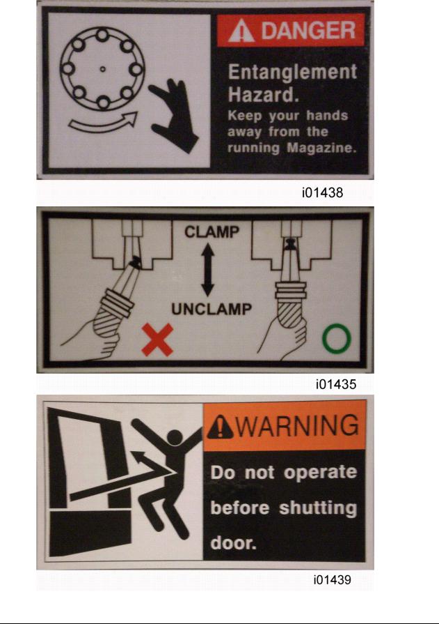
DANGER - Immediate hazards that will result in severe personal injury or death. Danger labels on the machine are red in color.
WARNING - Hazards or unsafe practices that could result in severe personal injury and/or damage to the equipment. Warning labels on the machine are orange in color.
CAUTION - Hazards or unsafe practices, which could result in minor personal injury or equipment/product damage. Caution labels on the machine are yellow in color.
NOTE - Call attention to specific issues requiring special attention or understanding.
HELPFUL TIP- A technique or tool that can aid you.
3
Southwestern Industries, Inc.
TRAK LPM Installation, Maintenance, Service, & Part List Manual

Safety & Information Labels Used On The
LPM Milling Machine
It is forbidden by OSHA regulations and by law to deface, destroy or remove any of these labels
4
Southwestern Industries, Inc.
TRAK LPM Programming, Safety, & Operating Manual
5
Southwestern Industries, Inc.
TRAK LPM Programming, Safety, & Operating Manual

6
Southwestern Industries, Inc.
TRAK LPM Programming, Safety, & Operating Manual

7
Southwestern Industries, Inc.
TRAK LPM Programming, Safety, & Operating Manual

2.3Safety Precautions
1.Do not operate this machine before the LPM Installation, Maintenance, Service and Parts List Manual, Operating & Care Manual have been studied and understood.
2.Do not run this machine without knowing the function of every control key, button, knob, or handle. Ask your supervisor or a qualified instructor for help when needed.
3.Protect your eyes. Wear approved safety glasses (with side shields) at all times.
4.Don't get caught in moving parts. Before operating this machine remove all jewelry including watches and rings, neckties, and any loose-fitting clothing.
5.Keep your hair away from moving parts. Wear adequate safety headgear.
6.Protect your feet. Wear safety shoes with oil-resistant, anti-skid soles, and steel toes.
7.Take off gloves before you start the machine. Gloves are easily caught in moving parts.
8.Remove all tools from the machine before you start. Loose items can become dangerous flying projectiles.
9.Never operate a milling machine after consuming alcoholic beverages, or taking strong medication, or while using non-prescription drugs.
10.Protect your hands. Stop the machine spindle and ensure that the CNC control is in the stop mode:
Before changing tools
Before changing parts
Before you clear away the chips, oil or coolant. Always use a chip scraper or brush.
Do not used compressed air to clean the machine.
Before you make an adjustment to the part, fixture, coolant nozzle or take measurements.
Do not attempt to disable any safety interlock. Never reach around a safeguard.
11.Protect your eyes and the machine as well.
12.Disconnect power to the machine before you change belts, pulley, and gears.
13.Keep work areas well lighted. Ask for additional light if needed.
14.Do not lean on the machine while it is running.
15.Prevent slippage. Keep the work area dry and clean. Remove the chips, oil, coolant and obstacles of any kind around the machine.
16.Avoid getting pinched in places where the table, saddle or spindle head create "pinch points" while in motion.
17.Securely clamp and properly locate the workpiece in the vise, on the table, or in a fixture. Use stop blocks to prevent objects from flying loose. Use proper holding clamping attachments and position them clear of the tool path.
18.Use correct cutting parameters (speed, feed, depth, and width of cut) in order to prevent tool breakage due to premature wear.
8
Southwestern Industries, Inc.
TRAK LPM Programming, Safety, & Operating Manual

19.Use proper cutting tools for the job. Pay attention to the rotation of the spindle: As viewed from above, left hand tool for counterclockwise rotation of spindle, and right hand tool for clockwise rotation of spindle.
20.To prevent damage to the workpiece or the cutting tool, never start the machine (including the rotation of the spindle) if the tool is in contact with the part.
21.Check the direction (+ or -) of movement of the table when using the jog feature, clockwise rotation of the EHW moves the axis in the positive direction, counterclockwise in the negative direction.
22.Don't use dull or damaged cutting tools. They break easily and become airborne. Inspect the sharpness of the edges, and the integrity of cutting tools and their holders. Use proper length for the tool.
23.Inspect the retention knobs for damage or excessive wear before each use.
24.Large overhang on cutting tools when not required result in accidents and damaged parts.
25.Prevent fires. When machining certain materials (magnesium, etc.) the chips and dust are highly flammable. Obtain special instruction from your supervisor before machining these materials.
26.Prevent fires. Keep flammable materials and fluids away from the machine and hot, flying chips.
Warning
Retention knobs come in a wide variety of designs, however they often look similar and appear to be interchangeable, but they are not. Use only the knob that the LPM is designed to use. The use of the incorrect knob, or the incorrect usage of a knob, may result in injury or property damage.
To ensure the correct knob is chosen, please refer to section 3.3.11, Machine Major Subassemblies section of this manual
9
Southwestern Industries, Inc.
TRAK LPM Programming, Safety, & Operating Manual

3.0 Description
This section will provide an overview of features and specifications found on the TRAK LPM.
3.1 Control Specifications
The new ProtoTRAK PMX CNC retains the basic operations strategies found in all other models of ProtoTRAK and TRAK CNCs.
3.1.1 ProtoTRAK PMX Hardware Specifications
Jog wheel for TRAKing and positioning 12.1” color active-matrix screen Industrial-grade Celeron® processor 512 MB Ram
4 User USB connectors Override of program feedrate
LED status lights built into display RJ45 Port with 10/100 Ethernet Override of program spindle speed 4th axis interface
Program storage via a USB flash drive installed in a port in the electrical cabinet.
3.1.2 ProtoTRAK PMX Software Specifications
Software Features - General Operation:
•Clear, uncluttered screen display
•Prompted data inputs
•English language – no codes
•Soft keys - change within context
•Windows® operating system
•Color graphics with adjustable views
•Inch/mm selectable
•Convenient modes of operation
•Absolute Home location
•Spindle load indicator
•Reference to ball lock locations on table
•Dimension reference indicator
•Selectable view between Current and Staged programs
DRO Mode features:
•Incremental and absolute dimensions
•Jog with selectable feed rates
•Powerfeed X, Y or Z
•Servo return to 0 absolute
•Go To Dimensions from convenient reference
•Spindle speed setting with manual override
•Selectable handwheel resolution
10
Southwestern Industries, Inc.
TRAK LPM Programming, Safety, & Operating Manual

• Convenient choice of dimensional references:
Machine Home, Part Zero, Abs Zero and Ball Lock locations
Program Mode Features
•Auto Geometry Engine
•Geometry-based programming
•Tool Path programming
•Scaling of print data
•Multiple fixture offsets
•Programming of Auxiliary Functions
•Event Comments
•Three-axis Geometry conversational programming
•Incremental and absolute dimensions
•Automatic diameter cutter comp
•Circular interpolation
•Linear interpolation
•Look –graphics with a single button push
•List step – graphics with programmed events displayed
•Alphanumeric program names
•Program data editing
•Program pause
•Conrad – automatic corner radius
•Programmable spindle speeds
•Math helps with graphical interface
•Auto load of math solutions
•Tool step over adjustable for pocket routines
•Pocket bottom finish pass
•Selectable ramp or plunge cutter entry
•Subroutine repeat of programmed events
•Nesting
•Rotate about Z-axis for skewing data
•Mirror of programmed events
•Copy
•Copy rotate
•Copy mirror
•Tool data entry in event programming
•Selectable retract in Bore operations
Auxiliary Functions
•Coolant on/off
•Air on/off
•Pulse indexer
•Part change table position
Canned Cycles
• Position
11
Southwestern Industries, Inc.
TRAK LPM Programming, Safety, & Operating Manual

•Drill
•Bolt Hole
•Mill
•Arc
•Circle pocket
•Rectangular pocket
•Irregular Pocket
•Circular profile
•Rectangular profile
•Irregular Profile
•Circle Island
•Rectangular Island
•Irregular Island
•Helix
•Thread milling
•Engrave
•Tapping
•Face Mill
Edit Mode Features
•Delete events
•Erase program
•Spreadsheet editing
•Global data change
•G-Code editor
•Clipboard to copy events between programs
•Move between subprograms in a master program
Program Set Up Mode Features
•Program diagnostics
•Advanced tool library
•Tool names
•Tool length offset with modifiers
•Tool diameters with modifiers
•Tool path graphics with adjustable views
•Program run time estimation clock
•Convenient part/fixture management screen
•Fixture offsets
•Part offsets within fixture
•Convenient manual tool handling when tools required exceed ATC capacity
•Photo storage and display
•Notes
•Z Safety Dimension to prevent crashes
•Tool Crib
•Tool by Tool or Part by Part run strategy
•Convenient Tool Reconciliation between programs and ATC
12
Southwestern Industries, Inc.
TRAK LPM Programming, Safety, & Operating Manual

• Convenient ATC capacity
Machine Set Up Mode Features
•Advanced diagnostic routines
•Software travel limits set in the factory
•Prompted Tool loading and ATC Management
•Checklist to assure nothing is forgotten
•Single key press to get to step needing attention
Run Mode Features
•TRAKing
•3D CAM file program run
•3D G code file run with tool comp
•Real time run graphics with tool icon
•Countdown clock for total part cycle time or manual tool change
•Error alarms prevent Run when set up steps are skipped
•Work on Staged programs while Current program runs
Program In/Out Mode Features
•CAM program converter
•Converter for prior-generation ProtoTRAK programs
•DXF/DWG file converter (Optional)
•Selection of file storage locations
•Automatic file back-up routine
•Preview graphics for unopened files
•Networking
•Create Master routine for combining programs
•Transfer of Staged program to Current
•Tool reconciliation for Master Programs
3.1.3 ProtoTRAK PMX Control Options
The DXF File Converter Option
•Import and convert CAD data into ProtoTRAK programs
•DXF or DWG files
•Chaining
•Automatic Gap Closing
•Layer control
•Easy, prompted process you can do right at the machine
CAM Out Converter Option
• Save ProtoTRAK files as CAM files for running on different controls
3.1.4 DXF File Converter Option
The DXF File Converter Option gives you powerful capability for quickly and easily translating DXF and DWG files into ProtoTRAK programs. If you work with CAD drawings, we highly recommend that you get a demo of the DXF file converter.
13
Southwestern Industries, Inc.
TRAK LPM Programming, Safety, & Operating Manual

To tell if the DXF File Converter is active on your ProtoTRAK PMX CNC, go to the options screen using Service Code #318. If the AutoCAD DXF option is in black letters, it is activated. If it is in gray letters, you will need to purchase the option to activate it. The DXF Option consists of an Activation Password, and may require an additional software update. To download the latest version of our DXF software, go to our website at www.southwesternindustries.com then click ‘Support & Software’ for current ProtoTRAK CNC, and follow the instructions for downloading the software via a USB flash drive. See Section 3.1.6 below for instructions on ordering and obtaining your Activation Password.
The DXF Option has its own manual which is shipped with the software. You may also view a copy of the manual on our web site.
3.1.5 CAM Out Option
Note: CAM file run by bringing a CAM file into the ProtoTRAK PMX is a standard feature.
The CAM out Option gives you the ability to create or modify a program using the easy, intuitive ProtoTRAK interface and then convert that program into a CAM file or G Code file to use to run other CNCs.
Note: you do not need the CAM Out option to share programs between ProtoTRAK CNCs.
To tell if the CAM Out feature is active on your ProtoTRAK PMX CNC, go to the options screen using Service Code #318. If the CAM Out option is in black letters, it is activated. If it is in gray letters, you will need to purchase the option to activate it. The software for the CAM Out Option requires an Activation Password for you to use. See Section 3.1.6 below for instructions on ordering and obtaining your Activation Password.
3.1.6 How To Buy Software Options
If you did not buy the software options described above with your machine, you may purchase them later. In order to use these options, a Software Activation Password is required. These passwords are unique to your ProtoTRAK PMX CNC.
Software Options are not free. You may call your local Southwestern Industries Sales Representative or Southwestern Industries Inside Sales at 310-608-4422 for a price quotation.
1. We recommend that you install the latest version of the ProtoTRAK PMX master software before installing the newest option. See our web site at www.southwesternindustries.com for software downloads.
14
Southwestern Industries, Inc.
TRAK LPM Programming, Safety, & Operating Manual
2.Go to the ProtoTRAK PMX CNC on which the option is to be installed, use Service Code 318 to go to the Software Options Screen.
3.Highlight the option you wish to install and press the softkey labeled INSTALL.
4.A screen will appear that advises you how to purchase the option. Near the bottom of the screen there will be a Hardware Key Serial Number and an Option Serial Number. Write down both of these numbers.
5.Call your Southwestern Industries Sales Representative or the Southwestern Industries Order Desk with your purchase order number and the numbers you wrote down in step 4 above.
6.When you receive your Password Activation Number, input it into the ProtoTRAK where indicated on the screen obtained in step 2 above. Some options require you to reboot the ProtoTRAK to activate.
7.Refer to the appropriate section of this manual for instructions on using your new features.
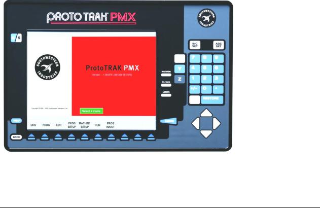
3.2 Display Pendant
The display pendant is integrated into the TRAK LPM on the front right side of the machine enclosure. The pendant may swing out 80º for your convenience and may be locked in place at 45º and 80º.
3.2.1 Program Panel
The Program Panel is the upper panel on the front of the Pendant.
INC SET: loads incremental dimensions and general data
ABS SET: loads absolute dimensions and general data
15
Southwestern Industries, Inc.
TRAK LPM Programming, Safety, & Operating Manual
RESTORE: clears an entry, aborts a keying procedure
INC/ABS: switches all or one axis from incremental to absolute or absolute to incremental position
IN/MM: causes Inch to Metric or Metric to Inch conversion of displayed data LOOK: part graphics in Program Mode
MODE: to change from one mode of operation to another
CURSOR: moves cursor of highlight in tables, lists or choices and pages between event. BACK: shifts LCD screen to previous display
HELP: display help information, Math Help or additional functions. Active for additional functions when the help symbol (a blue question mark) is displayed on the screen next to the HELP key.
C/S: switches Program Panel from current (the part program you are running) to staged (a different part program you are preparing to run in the future) and back. You can tell if you are in current or staged by the color of the Soft Keys: white Soft Keys tell you that you are in the Staged View.
Keyboard Soft Keys:
Beneath the display are 10 keys that are labeled with arrows. These keys are called software programmable or soft keys. A description of the function or use of each of these keys will be shown at the bottom of the display directly above each key. If, at any time, there is no description above a key, that key will not operate.
Sometimes the description or function of the key is visible but grayed out. This indicates that the particular function is not available because of some other condition. For example, if a program is not loaded into memory, then the softkey in Edit mode will be gray.
Emergency Stop Switch
The emergency stop (E-stop) switch kills all power to the spindle and ProtoTRAK's servomotors. The computer and pendant remain powered. To resume working from an emergency stop, you must twist to release the emergency stop button and press the green energize servos button.
The Liquid Crystal Display (LCD)
The display of the ProtoTRAK SMX CNC is a 12.4" active-matrix color LCD. The very top is the Status Line that shows the overall status of the ProtoTRAK SMX CNC. Status line information includes:
Current Mode
Current program part number
Current tool number
Whether the X, Y and Z dimensions are in inch or millimeter (mm).
Just above the soft keys is a data input line that appears when an input is required.
16
Southwestern Industries, Inc.
TRAK LPM Programming, Safety, & Operating Manual

3.2.2 Run Panel
The Run Panel is the lower panel on the front of the pendant.
Spindle Keys
FWD: turns the spindle on in the forward direction in DRO Mode OFF: turns the spindle off in the DRO Mode
REV: turns the spindle on in the reverse direction in the DRO mode
Feed Keys
GO: initiates axis motion in DRO Mode or during a stop condition in Run Mode STOP: halts axis motion
Electronic Hand Wheel Keys
Electronic Hand Wheel: used to control X, Y, Z axis positioning, spindle rpm override, and axis feed override. There are 100 positions or detents per revolution.
SPINDLE OVERRIDE: enables handwheel to control spindle rpm override from 0 to 150 percent in 2% increments.
FEED OVERRIDE: enables handwheel to control axis feed override from 0 to 150 percent in 2% increments.
EHW: enables handwheel to control positioning along X, Y, Z axes. X, Y, Z: selects axis to be controlled by Electronic Handwheel.
.0001in / .002mm: selects incremental axis motion per handwheel detent. One revolution equals (.0001in x 100) 0.01in.
.001in / .02mm: selects incremental axis motion per handwheel detent. One revolution equals (.001in x 100) 0.1in.
.01in / .2mm: selects incremental axis motion per handwheel detent. One revolution equals (.01in x 100) 1.0in.
FAST: selects fast axis motion for coarse movement up to 300 ipm.
Auxiliary Function Keys
COOLANT: press to turn coolant on (ON LED is lit). Press again to turn coolant on (AUTO LED is lit) when commanded by the program in Run Mode. Press again to turn coolant off.
17
Southwestern Industries, Inc.
TRAK LPM Programming, Safety, & Operating Manual
AIR: controls air blast from spindle to help clear chips. Press to turn air on (ON LED is lit). Press again to turn air on (AUTO LED is lit) when commanded by the program in Run Mode. Press again to turn air off.
WASH: press to activate chip wash to help move chips down to the chip auger location. DOOR LOCK: activates the door lock mechanism whenever a program or other automatic move is running. The LED light on the key is on when the door lock mechanism is active (it is possible for the door to be locked without the light being on). CHIP REMOVAL: press Forward (FWD) to activate chip auger, press again to turn off. Press and hold Reverse (REV) to drive chip auger in reverse to help clear jams (make sure FWD is off).
ATC INDEX: press forward (FWD) to index the automatic tool changer carousel forward by one tool. Press Reverse (REV) to index the automatic tool changer carousel backwards by one tool. The door must be closed.
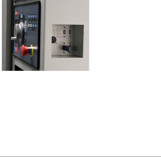
3.2.3 Pendant Right Side
Inset on the right side of the pendant are four USB ports for the thumb drive, keyboard, mouse, etc. Above these is a green Servo On button that must be pressed to activate machine motion following power start up or after the E Stop button is pressed.
18
Southwestern Industries, Inc.
TRAK LPM Programming, Safety, & Operating Manual
3.3 Machine Description
19
Southwestern Industries, Inc.
TRAK LPM Programming, Safety, & Operating Manual

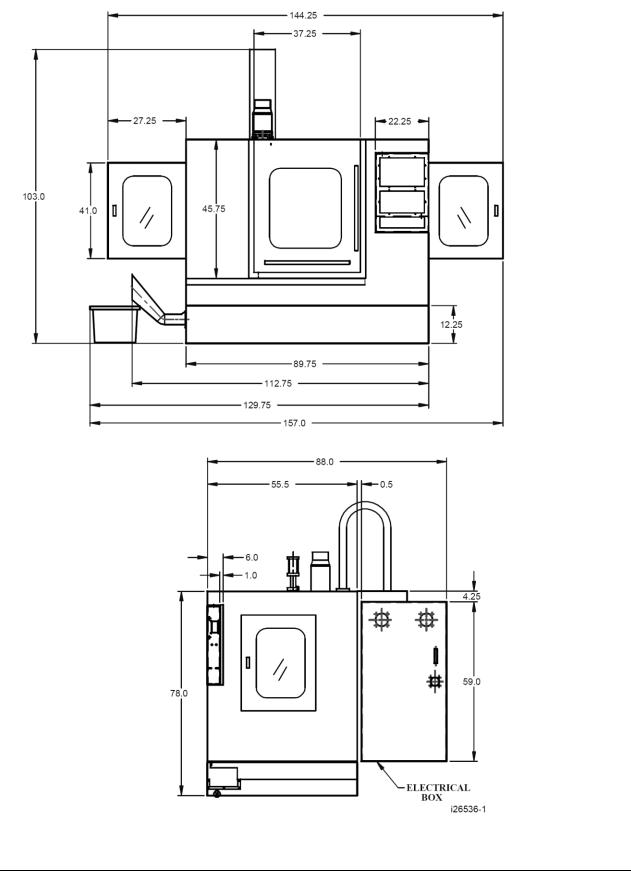
3.3.1 Overall Machine Dimensions |
|
|
Width of LPM without chip cart and auger chute |
89.75” |
|
Depth of LPM |
|
88” |
Height of LPM with head all the way up |
103” |
|
Width of LPM with chip cart and side doors open |
157” |
|
Minimum height to fit LPM through doorway (Z cable carrier collapsed) 85” |
||
Machine weight |
|
7650 lbs. |
3.3.2 Machine Specifications |
|
|
Table Dimensions |
|
|
Table size |
|
35.38” X 19.63” |
Number of tee slots and pitch |
|
5 @ 100 mm |
Tee slot width |
|
0.710” or 18 mm |
Table maximum load |
|
1000 lbs. |
Ball Lock ® hold down force |
|
2250 lbs @ 35 in/lbs of |
torque |
|
|
Travel |
|
|
X-axis |
|
31” |
Y-axis |
|
18.5” |
Z-axis |
|
21” |
Maximum distance from spindle nose table surface |
24” |
|
Minimum distance from spindle nose table surface |
3.375” |
|
Maximum swing clearance from spindle center to column |
19.25” |
|
Maximum Rapid speed X-axis, inches per minute |
800 |
|
Maximum Rapid speed Y-axis, inches per minute |
800 |
|
Maximum Rapid speed Z-axis, inches per minute |
700 |
|
Spindle |
|
|
Tool holder type |
|
CAT40 |
Spindle nose diameter |
|
2.75 |
Maximum RPM |
|
8000 |
Automatic Tool Changer |
|
|
Tool Capacity |
|
16 |
Maximum tool weight including holder |
15 lbs |
|
Maximum tool diameter |
|
3.14 |
Carousel speed |
|
.8 sec from station to station |
Tool selection system |
|
Bi-directional/ shortest path |
Retention knob |
|
See section 3.3.11 |
Air Requirements |
|
|
Pressure |
90 psi |
|
Quality |
Air dried/ water separator upstream of the LPM |
|
20
Southwestern Industries, Inc.
TRAK LPM Programming, Safety, & Operating Manual

3.3.3 Maximum Spindle Torque and Horsepower
The following graphs illustrate the continuous and peak torque vs. RPM and horsepower vs. RPM for the LPM machine at the spindle. Peak torque and horsepower values can only be attained for a short period of time before the spindle drive will fault out to protect the motor.
|
|
|
Torque vs RPM |
||
|
60 |
|
|
|
|
|
50 |
|
|
|
|
-lbs) |
40 |
|
|
|
|
|
|
|
|
|
|
(ft |
30 |
|
|
|
Continuous Torque |
|
|
|
|
||
Torque |
|
|
|
Peak Torque |
|
|
|
|
|
||
|
|
|
|
|
|
|
20 |
|
|
|
|
|
10 |
|
|
|
|
|
0 |
|
|
|
|
|
0 |
2000 |
4000 |
6000 |
8000 |
|
|
|
RPM |
|
|
HP vs RPM
|
16 |
|
|
|
|
|
14 |
|
|
|
|
|
12 |
|
|
|
|
|
10 |
|
|
|
|
HP |
8 |
|
|
|
|
|
|
|
|
|
|
|
6 |
|
|
|
|
|
4 |
|
|
|
|
|
2 |
|
|
|
|
|
0 |
|
|
|
|
|
0 |
2000 |
4000 |
6000 |
8000 |
|
|
|
RPM |
|
|
Continuous HP
Peak HP
21
Southwestern Industries, Inc.
TRAK LPM Programming, Safety, & Operating Manual

Note - Maximum work capacities are dependent on a lot of variables that cannot be controlled by the machine manufacturer. Each one of the following will have an impact on the above numbers: speeds, feeds, cutter, cutter sharpness, material, setup, coolant and machine adjustments.
3.3.4 Electrical Cabinet
The electrical cabinet is found at the rear of the LPM on the right side. The electrical cabinet contains the main control hardware for the machine. The main components are as follows: computer module, AC spindle drive, servo drives, input/output modules, relays and contactors.
3.3.5 Computer Module
The computer module is the heart and soul of the machine. All of the inputs and outputs are feed through this module. The computer module controls the program panel, run panel, AC spindle drive, servo drives, motor signals and feedback and input/output modules. Inside of the computer module is a motherboard, motion control board and an applications board along with a power supply.
The computer module also contains 4 more USB ports and a network port. We ship the machine with 3 USB ports having something plugged into them. The 3 USB ports contain the following: machine option key, a D drive for part storage and an overlay interface USB cable. The network port is available to the user if they want to network the control to an offline computer or network.
3.3.6 Servo Motors
The LPM can run up to 4 axis motors. The 4th motor would be used to control a 4th axis indexer. The motors used on the X and Y axis are rated for 4.2 ft/lbs of torque. The Z axis motor is rated at 8.11 ft/lbs and also contains a mechanical brake the holds the head in position when the power is turned off to the machine.
3.3.7 Servo Drives
The LPM can also contain up to 4 servo drives. The 4th amp would be used to control a 4th axis indexer or rotary table. The servo drives receive signals from the computer module, which in turn send signals to the servo motors.
3.3.8 Spindle
The spindle is contained within a cartridge and CAT 40 tool holders must be used. The spindle bearings are permanently lubricated and require no additional attention by the user. The spindle is also air cooled, and has an air purge system that is automatically activated during the tool change sequence, it blows air down the spindle to prevent chips from being trapped between the holder and spindle taper.
Warning!
The spindle unit is not field serviceable. If the bearings go bad the entire spindle cartridge will be replaced.
22
Southwestern Industries, Inc.
TRAK LPM Programming, Safety, & Operating Manual
3.3.9 Spindle Motor & Drive
The spindle motor is 10 HP and drives the spindle via a timing belt. The ratio between the spindle and spindle motor is 1 to 1. The RPM range for this machine is 150 to 8000 RPM.
3.3.10 Automatic Draw Bar Assembly
The automatic drawbar is an assembly consisting of an air cylinder and an actuator that unclamps the tool. Tooling is changed by means of the Automatic Tool Changer (ATC), or can be done manually by pressing and holding the “Unclamp” button. Tools are clamped when the button is released. A clamping force of approximately 1500 lbs is generated to clamp the toolholder to the spindle. The Automatic Draw Bar Assembly uses full system air and requires no adjustment. The air cylinder that does the clamping and unclamping is lubricated with a small cup. Make sure to check the oil level in this cup on a regular basis.
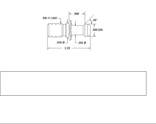
3.3.11 Retention Knobs
The LPM uses CAT40 retention knobs as shown below. Tightening to the proper torque value is important for all retention knobs. Please see the retention knob manufacturer for the proper torque.
Retention knobs
Warning!
Retention knobs come in a wide variety of designs, however they often look similar and appear to be interchangeable, but they are not. Use only the knob that the LPM is designed to use. The use of the incorrect knob, or the incorrect use of a knob, may result in injury and/or damage to the mechanism.
23
Southwestern Industries, Inc.
TRAK LPM Programming, Safety, & Operating Manual
3.3.12 Tool Changer
The tool changer is an armless carousel type automatic tool changer that has a capacity of 16 tools. The carousel is mechanically indexed by means of a Geneva mechanism. The position of the carousel is controlled by a signal from Home Position Sensor. As an additional safety feature, the ATC also has Tool Detect Sensor at the “ready position”. This means if a tool is sitting in this position and the control tries to put the tool in the spindle into this spot, an error will be generated by the control.
3.3.13 Drive Train, Axes
Each axis (X, Y and Z) rides on precision linear guideways, with four preloaded recirculating ball carriages. Each axis is moved via an 8 mm pitch ballscrew. The axis motors direct drive the ballscrew.
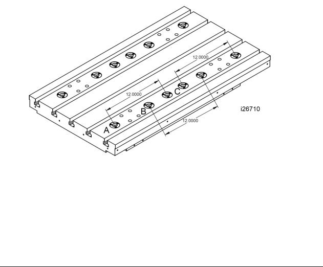
3.3.14 Worktable
The LPM table utilizes Ball Lock® technology as well as conventional T-bolt construction. Each Ball Lock mechanism has a hold-down force of 2250 lbs when 35 in/lbs of torque is applied to the screw. The software on the LPM is based on these ball locks as we ask the user which ball lock location they wish to run the part on. The 3 locations are called ball lock A, B and C.
3.3.15Limit/Home Switches
Each axis has a limit switch, which serve two purposes, to protect the LPM in the event of an over-travel situation in either the positive or negative direction, and secondly for the purpose of homing the machine. The following table describes where the cams are that trigger the limit switches.
24
Southwestern Industries, Inc.
TRAK LPM Programming, Safety, & Operating Manual

Limit Switch Cam Locations
Axis End |
Location of Cam Bracket |
Cam Location |
X-axis Negative End |
Left hand side of the table (front) |
Upper channel |
X-axis Positive End |
Right hand side of the table (front) |
Lower channel |
Y-axis Negative End |
On the base casting, beneath the saddle |
Upper channel |
|
(back) |
|
Y-axis Positive End |
On the base casting, beneath the saddle |
Lower channel |
|
(front) |
|
Z-axis Negative End |
On the column casting (upper) |
Right hand channel |
Z-axis Positive End |
On the column casting (lower) |
Left hand channel |
ATC Home Position |
ATC shroud |
Target bolt on the |
Sensor |
|
carousel |
ATC Sliding Body, |
Bracket-Sliding Body Support, left |
Sliding Body |
home |
|
|
ATC Sliding Body, |
Bracket-Sliding Body Support, right |
Sliding Body |
Advanced |
|
|
|
|
|
|
WARNING! |
|
It is not recommended that the position of the limit switches be |
||
changed. They are preset at the factory and should require no |
||
additional adjustments. Should any major adjustments be required, Service Codes 500, 501, 502 and 505 may need to be performed.
3.3.16 Lubrication System
The automatic lubricating system is a centralized system. It is located at the rear of the machine. While the system is automatic, it is recommended that after long idle periods, the machine be manually lubricated by pressing, holding (about five seconds) until the system is charged, then releasing the square green button located on the lubricator, repeat three to five times. The lubricating system delivers 2 shots of oil when the machine is turned on at the disconnect switch, and 1 shot every 30 minutes while the machine is running. The lubrication reservoir should be maintained on a daily basis, filling only with high quality lubricating oil. All pneumatic components are lubricated by means of an inline oiler.
3.3.17 Coolant and Coolant Wash System
The coolant and coolant wash system uses two pumps, one for providing coolant to the work, and the other for washing the chips into the auger. Wash areas can be controlled by the flexible coolant lines found at the base of the enclosure, both left and right-hand sides. Coolant wash can also be done with the use of the hose and nozzle found on the front exterior of the enclosure. The coolant feature must be turned on at the hard key on the Run Panel.
The coolant tank holds approximately 55 gallons of coolant.
25
Southwestern Industries, Inc.
TRAK LPM Programming, Safety, & Operating Manual
Loading...