


ProTURN SLX 1630
ProtoTRAK SLX CNC
Safety, Installation, Maintenance,
Service & Parts List Manual
Document: 25099
Version: 032813
Southwestern Industries, Inc.
2615 Homestead Place |
|
|||
Rancho |
Dominguez, |
CA |
90220-5610 USA |
|
T |
| 310.608.4422 |
| |
F | 310. 764.2668 |
|
Service |
Department: |
800.367.3165 |
||
e-mail: sales@southwesternindustries.com |
||||
| |
service@southwesternindustries.com |
|||
| |
web: |
southwesternindustries.com |
|
|
Copyright © 2011, XYZ Machine Tools, Ltd. All rights are reserved. No part of this publication may be reproduced, stored in a retrieval system, or transmitted, in any form or by any means, mechanical, photocopying, recording or otherwise, without the prior written permission of XYZ Machine Tools, Ltd.
While every effort has been made to include all the information required for the purposes of this guide, XYZ Machine Tools assumes no responsibility for inaccuracies or omission and accepts no liability for damages resulting from the use of the information contained in this guide.
All brand names and products are trademarks or registered trademarks of their respective holders.
XYZ Machine Tools
Woodlands Business Park
Burlescombe, Nr Tiverton
Devon, EX16 7LL
Service Department
Tel: 01823 674214
Fax: 01823 674201

Table of Contents
1.0 |
Safety Specifications |
|
|
3.3.10 |
Will Not Hold Calibration |
29 |
||
1.1 |
Safety Publications |
1 |
|
3.3.11 |
E-Stop Error |
29 |
||
3.4 |
Problems with the Measurements |
30 |
||||||
1.2 |
Safety Precautions |
2 |
||||||
|
3.4.1 |
X & Z-Axis Measurements Do Not |
|
|||||
|
|
|
|
|
|
|||
2.0 |
Installation |
|
|
|
Repeat |
30 |
||
|
|
3.4.2 |
X & Z-Axis Measurements are not |
|
||||
2.1 |
Floor Plan, Layout & Space Requirements |
5 |
|
|
||||
|
|
Accurate |
31 |
|||||
2.2 |
Uncrating |
6 |
|
|
||||
|
3.4.3 |
The DRO is not Counting |
31 |
|||||
2.3 |
Shortages: Inventory Checklist |
6 |
|
|||||
|
3.4.4 |
X & Z-Axis DRO Counting in the |
|
|||||
2.4 |
Installation, Instructions & Checklist |
7 |
|
|
||||
|
|
Wrong Direction |
31 |
|||||
2.5 |
Machine Specifications |
9 |
|
|
||||
|
3.4.5 |
X & Z-Axis Electric Handwheels |
|
|||||
2.6 |
ProtoTRAK SLX Control Hardware |
10 |
|
|
||||
|
|
Turn in Wrong Direction |
32 |
|||||
2.7 |
Lifting and/or Moving the Machine |
10 |
|
|
||||
3.5 |
Problems with the Machine Tool |
32 |
||||||
2.8 |
Cleaning |
12 |
||||||
|
3.5.1 |
Spindle Stalls or Turns Off During |
|
|||||
2.9 |
Leveling |
12 |
|
|
||||
|
|
Machining |
32 |
|||||
|
2.9.1 |
SLX 1630 |
13 |
|
|
|||
|
|
3.5.2 |
Spindle Motor Hums or Will Not |
|
||||
2.10 |
Electrical Connection |
13 |
|
|
||||
|
|
Run |
32 |
|||||
|
2.10.1 |
Phase Converters |
14 |
|
|
|||
|
|
3.5.3 |
Spindle Runs Backwards |
32 |
||||
2.11 |
Mounting the Display Pendant |
14 |
|
|||||
|
3.5.4 |
Excess Gearbox Noise |
33 |
|||||
2.12 |
Cable Interconnections |
15 |
|
|||||
|
3.5.5 |
Headstock is Leaking Oil |
33 |
|||||
2.13 |
Lubrication System |
18 |
|
|||||
|
3.5.6 |
Tailstock Barrel is Stiff |
33 |
|||||
|
2.13.1 |
Headstock |
18 |
|
||||
|
|
|
|
|
||||
|
2.13.2 Automatic Way Lubrication Pump |
19 |
4.0 |
Diagnostics |
|
|||
|
2.13.3 |
Lube Pump Operation |
19 |
|
||||
|
4.1 |
The Machine Tool & Set Up |
35 |
|||||
|
2.13.4 |
Factory Default Values |
19 |
|||||
|
|
4.1.1 |
Leveling |
35 |
||||
2.14 |
Cutting the Test Part |
20 |
|
|||||
|
4.1.2 |
A Special Word about the X Gib |
35 |
|||||
2.15 |
Measurement of the Test Part |
20 |
|
|||||
|
4.1.3 |
Lubrication |
35 |
|||||
|
|
|
|
|
||||
3.0 |
Troubleshooting by Symptom |
|
|
4.1.4 |
Machining Set-Up |
35 |
||
|
4.2 |
The Mechanical Drive Train (X, Z) |
37 |
|||||
3.1 |
Problems relating to Machining Results |
21 |
||||||
4.3 |
Computer/Pendant Diagnostics |
38 |
||||||
|
3.1.1 |
Poor Finish |
21 |
|||||
|
4.4 |
Motor Diagnostics |
39 |
|||||
|
3.1.2 |
Turning Diameters out of Round |
22 |
|||||
|
|
4.4.1 |
Cable Connections |
39 |
||||
|
3.1.3 |
Cutting Taper |
22 |
|
||||
|
|
4.4.2 |
To Check the Motor Encoders |
40 |
||||
|
3.1.4 |
Parts have Incorrect Dimensions |
22 |
|
||||
|
|
4.4.3 |
Encoder Counts to Pendant |
40 |
||||
|
3.1.5 |
Threading Problems |
23 |
|
||||
|
|
4.4.4 |
Moving Problem from One Axis |
|
||||
3.2 |
Problems regarding the Motion |
|
|
|
||||
|
|
|
to Another |
40 |
||||
|
of the Machine |
23 |
|
|
||||
|
4.5 |
Servo Drivers |
40 |
|||||
|
3.2.1 |
Run Away Axis |
23 |
|||||
|
4.6 |
Electrical |
|
41 |
||||
|
3.2.2 |
Slow Down Axis |
24 |
|
||||
|
|
4.6.1 |
Checking A/C Voltage |
41 |
||||
|
3.2.3 |
Axis will not Jog |
24 |
|
||||
|
|
4.6.2 |
Checking Fuses |
41 |
||||
|
3.2.4 |
Axis Motor Motion is not Smooth |
25 |
|
||||
|
|
4.6.3 |
Main Electrical Box |
42 |
||||
|
3.2.5 |
Vibration in Motion |
25 |
|
||||
|
|
4.6.4 |
Cable Breakout Box Connections |
48 |
||||
|
3.2.6 |
Searching Axis |
26 |
|
||||
|
|
4.6.5 |
Cable Connections |
48 |
||||
3.3 |
Problems Relating to the Operation Control |
26 |
|
|||||
4.7 |
Door Interlock Switch |
49 |
||||||
|
3.3.1 |
Display Blanks |
26 |
|||||
|
4.8 |
Service Codes |
49 |
|||||
|
3.3.2 |
Bad Picture on the Display |
26 |
|||||
|
|
4.8.1 |
Software Codes |
49 |
||||
|
3.3.3 |
Keyboard Lockup |
26 |
|
||||
|
|
4.8.2 |
Machine Set-Up Codes |
50 |
||||
|
3.3.4 |
Fault X or Z |
27 |
|
||||
|
|
4.8.3 |
Diagnostic Codes |
53 |
||||
|
3.3.5 |
Problems Reading the Floppy Disk |
27 |
|
||||
|
|
4.8.4 |
Operator Defaults/Options Codes |
54 |
||||
|
3.3.6 |
System Will Not Turn ON |
28 |
|
||||
|
|
|
|
|
||||
|
3.3.7 |
System Will Not Boot Up |
28 |
5.0 |
Procedures for Replacements & |
|
||
|
3.3.8 |
System Reboots by Itself |
28 |
|
||||
|
|
Maintenance |
|
|||||
|
3.3.9 |
System Shuts Off |
28 |
|
|
|||
|
|
|
|
5.1 |
Replacements |
57 |
||
|
|
|
|
|
5.1.1 |
Motor Replacement |
57 |
|
|
|
|
|
|
5.1.2 |
Servo Driver Replacement |
57 |
|
i
XYZ Machine Tools
ProTURN SLX 1630 ProtoTRAK SLX CNC Safety, Installation, Service & Parts List Manual

5.1.3 |
Computer Module Replacement |
57 |
5.1.4 |
System Flash Disk Replacement |
60 |
5.1.5 |
Cable Routing on Machine |
62 |
5.1.6 |
Electronic Handwheels & Jogstick |
62 |
5.1.7 |
Cable Routing in Electrics Box |
62 |
5.1.8 |
Spindle Drive Belt Replacement |
62 |
5.1.9 |
Spindle Motor Removal |
63 |
5.1.10 |
Spindle Encoder Replacement |
63 |
5.1.11. |
X-Axis Ball Screw Removal |
63 |
5.1.12Installing Angular Contact Bearings 67
|
5.1.13 |
Z-Axis Ball Screw Removal |
68 |
|
5.1.14 |
Align Z-Axis Ball Screw Assembly |
68 |
|
5.1.15 |
Headstock Taper Adjustment |
72 |
|
5.1.16 |
Spindle Bearing Preload |
72 |
|
5.1.17 |
Aligning Tailstock to Spindle |
73 |
|
5.1.18 |
Spindle Motor Wiring |
73 |
5.2 |
Maintenance |
74 |
|
|
5.2.1 |
Gib Adjustments |
74 |
|
5.2.2 |
Calibration & Backlash Constants |
76 |
|
5.2.3 |
Lubrication |
78 |
6.0Indexer Options
6.1 |
Dorian Indexer Option |
83 |
|
|
6.1.1 |
Field Installation Instructions |
83 |
|
6.1.2 |
Removing the Indexer from the |
|
|
|
Lathe |
83 |
|
6.1.3 |
Troubleshooting the Indexer |
84 |
|
6.1.4 |
Troubleshooting from LED’s in |
|
|
|
Black Box |
84 |
|
6.1.5 |
Indexer Encoder Re-Alignment |
85 |
|
6.1.6 |
Indexer Maintenance |
85 |
|
6.1.7 |
Warranty Issues |
85 |
6.2 |
4 Tool Indexer Option |
88 |
|
|
6.2.1 |
Field Installation Instructions |
88 |
|
6.2.2 |
Removing the Indexer from the |
|
|
|
Lathe |
88 |
|
6.2.3 |
Troubleshooting the Indexer |
89 |
|
6.2.4 |
Troubleshooting the Cable |
|
|
|
Breakout Box |
89 |
7.0Drawings & Parts Lists
Fig. 1 |
SLX 1630 Floor Plan, Layout & Space |
|
|
Specifications |
5 |
Fig. 2 |
Anchor Bolt Specifications |
6 |
Fig. 3 |
Lifting SLX 1630 & 1840SX |
11 |
Fig. 4 |
Leveling |
13 |
Fig. 5 |
Wiring the 1630 & 1840 |
14 |
Fig. 6 |
Cable Connections |
16 |
Fig. 7 |
Pendant Cable Connections, Left Side |
17 |
Fig. 8 |
Pendant, Right Side |
18 |
Fig. 9 |
Taper Test |
20 |
Fig. 10 |
Electrical Box Parts |
43 |
Fig. 11 |
Spindle Control Module LED’s |
47 |
Fig. 12 |
Computer Module & LCD/Enclosure |
|
|
Replacement |
59 |
Fig. 13 |
Flash Disk Replacement |
61 |
Fig. 14 |
Spindle Drive Belt/Motor Mounting |
63 |
Fig. 15 |
1630 X-Axis Drive Train |
64 |
Fig. 16 |
Angular Control Bearings |
67 |
Fig. 17 |
1630 Z-Axis Drive Train |
69 |
Fig. 18 |
Headstock Alignment |
72 |
Fig. 19 |
Tailstock Alignment |
73 |
Fig. 20 X-Axis Gib Adjustment |
75 |
|
Fig. 21 |
Z-Axis Gib |
76 |
Fig. 22 |
Calibration Set-Up |
77 |
Fig. 23 SLX 1630 & 1840SX Lubrication |
80 |
|
Fig. 24 |
Tailstock Oil |
80 |
Fig. 25 |
Indexer Mounting |
86 |
Fig. 26 Indexer Cable Routing |
87 |
|
Fig. 27 Motor Drive Adjustment & PLC Inputs & |
|
|
|
Outputs |
92 |
Fig. 28 Indexer Mounting Cable Breakout Box |
93 |
|
Fig. 29 4 Tool Indexer Cable Routing |
94 |
|
Fig. 30 Lathe Apron Assembly |
97 |
|
Fig. 31 1630 Machine Assembly |
99 |
|
Fig. 32 1630 Machine Assembly |
100 |
|
Fig. 33 1630 Machine Assembly |
101 |
|
Fig. 34 1630 Headstock Assembly |
104 |
|
Fig. 35 1630 Headstock Assembly |
105 |
|
Fig. 36 1630 Tailstock Assembly |
108 |
|
Fig. 37 1630 Tailstock Assembly |
109 |
|
Fig. 38 1630 Tailstock Assembly |
110 |
|
ii
XYZ Machine Tools
ProTURN SLX 1630 ProtoTRAK SLX CNC Safety, Installation, Service & Parts List Manual

1.0 Safety Specifications
The safe operation of the PROTURN SLX 1630 depends on its proper use and the precautions taken by each operator.
Read and study the PROTURN SLX 1630 CNC Safety, Programming, Operating, and Care Manual. Be certain that every operator understands the operation and safety requirements of this machine before its use.
Read and study this PROTURN SLX 1630 Safety, Installation, Maintenance, Service & Parts List Manual. Be certain that every operator understands the operation and safety requirements of this machine before servicing.
Always wear safety glasses and safety shoes.
Always stop the spindle and check to ensure the CNC control is in the stop mode before changing or adjusting the tool or workpiece.
Never wear gloves, rings, watches, long sleeves, neckties, jewelry, or other loose items when operating, or around the machine.
Use adequate point of operation safeguarding. It is the responsibility of the employer to provide and ensure point of operation safeguarding.
STATEMENT OF INTENDED USE
To be used for the turning of cold metal within the stated capacity of the lathe, axes movement by manual use of handwheels or CNC control.
Only to be operated by trained and experienced operators.
To be used in a standard workshop environment, not suitable for potentially explosive atmosphere.
Any other uses should first be subjected to a risk assessment by a responsible person.
1.1 Danger, Warning, Caution, and Note Labels and Notices As Used In This Manual
DANGER - Immediate hazards that will result in severe personal injury or death. Danger labels on the machine are red in color.
WARNING - Hazards or unsafe practices that could result in severe personal injury and/or damage to the equipment. Warning labels on the machine are gold in color.
CAUTION - Hazards or unsafe practices that could result in minor personal injury or equipment/product damage. Caution labels on the machine are gold in color.
NOTE - Call attention to specific issues requiring special attention or understanding.
1
XYZ Machine Tools
ProTURN SLX 1630 ProtoTRAK SLX CNC Safety, Installation, Service & Parts List Manual

1.2 Safety Precautions
WARNING!
Use only chucks which are rated to the maximum RPM of the lathe.
1.Do not operate this machine before the PROTURN SLX 1630 ProtoTRAK SLX CNC Programming, Operating and Care Manual have been studied and understood.
2.Read and study this PROTURN SLX 1630 Safety, Installation, Maintenance, Service & Parts List Manual. Be certain that every operator understands the operation and safety requirements of this machine before servicing.
3.Do not run this machine without knowing the function of every control key, button, knob, or handle. Ask your supervisor or a qualified instructor for help when needed.
4.Protect your eyes. Wear approved safety glasses (with side shields) at all times. Do not rely on the lexan vision panels for eye protection.
5.Don't get caught in moving parts. Before operating this machine, remove all jewelry, including watches and rings, neckties, and any loose-fitting clothing.
6.Keep your hair away from moving parts. Wear adequate safety headgear.
7.Protect your feet. Wear safety shoes with oil-resistant, anti-skid soles, and steel toes.
8.Take off gloves before you start the machine. Gloves are easily caught in moving parts.
9.Remove all tools (wrenches, chuck keys, etc.) from the machine before you start. Loose items can become dangerous flying projectiles.
10.Never operate any machine tool after consuming alcoholic beverages, or taking strong medications, or while using non-prescription drugs.
11.Protect your hands. Stop the machine spindle and ensure that the CNC control is in the STOP mode:
Before changing tools.
Before changing parts.
Before you clear away the chips, oil or coolant. Always use a chip scraper or brush.
Before you make an adjustment to the part, chuck, coolant nozzle or take measurements.
Before you open safeguards (protective shields, etc.). Never reach for the part, tool, or fixture around a safeguard.
12.Protect your eyes and the machine as well. Don't use a compressed air hose to remove the chips or clean the machine (oil, coolant, etc.).
13.Stop and disconnect the power to the machine before you change belts, pulley, gears, etc.
14.Keep work area well lighted. Ask for additional light if needed.
15.Do not lean on the machine while it is running.
2
XYZ Machine Tools
ProTURN SLX 1630 ProtoTRAK SLX CNC Safety, Installation, Service & Parts List Manual

16.Prevent slippage. Keep the work area dry and clean. Remove the chips, oil, coolant and obstacles of any kind around the machine.
17.Avoid getting pinched in places where the spindle, carriage, cross slide or sliding door create "pinch points" while in motion.
18.Securely clamp and properly locate the workpiece in the chuck or in the fixture. Use proper tool holding equipment.
19.Use correct cutting parameters (speed, feed, and depth of cut) in order to prevent tool breakage.
20.Use proper cutting tools for the job.
21.Prevent damage to the workpiece or the cutting tool. Never start the machine (including the rotation of the spindle) if the tool is in contact with the part.
22.Don't use dull or damaged cutting tools. They break easily and may become airborne. Inspect the sharpness of the edges, and the integrity of cutting tools and their holders.
23.Large overhangs on cutting tools when not required result in accidents and damaged parts.
24.Prevent fires. When machining certain materials (magnesium, etc.) the chips and dust are highly flammable. Obtain special instruction from your supervisor before machining these materials. Do a risk assessment before machining flammable materials.
25.Prevent fires. Keep flammable materials and fluids away from the machine and hot, flying chips.
26.Do not rotate the spindle by hand unless the Red Emergency Stop button is pressed.
3
XYZ Machine Tools
ProTURN SLX 1630 ProtoTRAK SLX CNC Safety, Installation, Service & Parts List Manual
2.0 Installation
Read and understand this entire installation section before beginning the installation procedure.
2.1 Floor Plan, Layout & Space Requirements
Figure 1 (May not represent actual machine)
SLX 1630 Floor Plan, Layout & Space Requirements
4
XYZ Machine Tools
ProTURN SLX 1630 ProtoTRAK SLX CNC Safety, Installation, Service & Parts List Manual

2.2 Uncrating
Carefully remove the protective packaging, paying attention not to scratch, damage, or mar any parts of the machine.
Remove the cardboard boxes with the PENDANT DISPLAY (handle carefully). The leveling pads and screws for the machine can be found in the toolbox.
Loosen and remove 4 screws and nuts holding the machine to the wood pallet.
ATTENTION!
Immediately report, in writing, any damages observed at this time that can be attributed to the transportation or improper handling/moving of the machine.
2.3 Shortages: Inventory Checklist
______Machine (check model and serial number)
______Leveling pads and screws (4 for 1630)
______Pendant Display (24000-4)
______Pendant Cable Cover (24324)
______Toolbox with various tools
______SLX 1630 Safety, Operation & Programming Manual (P/N 24494)
______SLX 1630 ProtoTRAK SLX CNC Safety, Install, Maint, Service & Parts List Manual (P/N 25099)
In case of shortages, contact the representative from whom you purchased the machine.
5
XYZ Machine Tools
ProTURN SLX 1630 ProtoTRAK SLX CNC Safety, Installation, Service & Parts List Manual
|
|
2.4 Installation Instructions & Checklist |
||
|
|
|
Installer: Use this checklist to assure a complete set-up of the SLX 1630. * Items |
|
|
|
|
checked before leaving the factory |
|
|
|
|
||
|
1. |
Shut off power to the machine. |
||
|
2. |
Visually inspect the 415V going into the electrical panel. Visually verify the wiring is correct per |
||
|
|
|
our wiring diagram. Make sure a strain relief is being used where the wiring enters the cabinet. |
|
|
|
|
Have the customer repair any wiring discrepancies. Note: Machine can only be wired for 415 |
|
|
|
|
VAC. |
|
|
3. |
Clean the machine if needed and remove any remaining grease. |
||
|
4. |
Mount the pendant on the bracket that is attached to the chip enclosure for the 1630. |
||
|
5. |
Make and check all the proper electrical connections from the pendant to the electric box. Be |
||
|
|
|
sure to mount the cable cover to the left side of the pendant. |
|
|
6. |
Slide the doors back and forth to make sure they slide smoothly. Adjust as necessary. |
||
|
7. |
Remove the protective plastic covers from the headstock and the windows on the sliding doors. |
||
|
8. |
Turn on the power to the machine and to the pendant. Make sure that the 115-volt line is |
||
|
|
|
plugged into the pendant. |
|
|
9. |
Check to make sure the coolant pump is rotating in the correct direction. |
||
|
10. |
Visually inspect the oil level through the site glass which is found under the rear spindle cover |
||
|
|
|
and verify that the oil level is correct in the head stock prior to turning on the machine tool. Add |
|
|
|
|
oil if necessary. Make a notation on the installation summary sheet if the oil level is incorrect. |
|
|
|
|
For the 1630, oil will only be visible on the headstock site glass when the spindle is running. |
|
|
11. |
Manually override the automatic way oiler and pump oil to lubricate all sliding surfaces. This can |
||
|
|
|
be done by running service code 300 a few times. |
|
|
12. |
Jog the saddle and cross slide back and forth until the way surfaces are well lubricated. Oil |
||
|
|
|
should be visible on all the way surfaces. |
|
|
13. |
Position the saddle and tailstock to the center of the bed for leveling. |
||
|
14. |
Check the level of the machine. The machine should be level to within 0.02 mm longitudinally |
||
|
|
|
and 0.01 mm transversely. Even though it is the responsibility of the customer, make any |
|
|
|
|
adjustments if necessary (see section 2.9 Leveling). |
|
|
15. |
Check the tailstock and the tailstock barrel locks by locking and unlocking. Run the tailstock |
||
|
|
|
barrel in and out to ensure proper function. |
|
|
16. |
Run the spindle at 500 rpm or so for 15 to 20 minutes in order to warm the headstock. * |
||
|
17. |
Run the spindle through it's various speeds. |
||
|
18. |
Open and close the doors and verify the door switches are functional. The control should |
||
|
|
|
display a message of “DOOR OPEN” in DRO mode when the doors are open and it should |
|
|
|
|
disappear when the doors are closed. Open and close the chuck guard and verify a message is |
|
|
|
|
present on the screen and the spindle does not run with the chuck guard open. |
|
|
19. |
Make sure the X and Z electronic handwheels and jogstick are functional. |
||
|
20. |
Check to make sure that the E-Stop button on the pendant is functioning correctly. The 1630 |
||
|
|
|
only has an e-stop on the pendant. Undo the e-stop ad press the screen button on the right |
|
|
|
|
side of the pendant to reset. |
|
|
21. |
Perform Service Code 12, Feed Forward Constant.* |
||
|
22. |
Perform Service Code 123 to calibrate the X and Z-axis using a 150mm standard. * |
||
|
23. |
Perform Service Code 127 and 128 to manually calculate the backlash for the X and Z-axis.* |
||
|
24. |
Check for positional accuracy and repeatability on the X and Z-axis using programs X LATHE |
||
|
|
|
REPEAT.PT4 and Z LATHE REPEAT.PT4 respectively. Positioning and repeatability values should |
|
|
|
|
be less than or = to 0.01 mm. Programs can be found on the parts program disk that comes |
|
|
|
|
with each pendant. It may also be found in the PT4 folder followed by the SWI TEST |
|
|
|
|
PROGRAMS folder if the customer ordered the Network/Memory software option. Note: the |
|
|
|
|
doors must be closed to run these programs.* |
|
|
25. |
Perform Service Code 100 in both directions for the X and Z-axis to verify that the feed rate |
||
|
|
|
shown on the display is at least 4572 mm/min (180 ipm) for Z and 3048 mm/min (120 ipm) for |
|
|
|
|
X.* |
|
|
|
|
6 |
|
|
|
|
XYZ Machine Tools |
|
|
|
|
ProTURN SLX 1630 ProtoTRAK SLX CNC Safety, Installation, Service & Parts List Manual |
|
|
26. |
Use accessory key on pendant and make sure the coolant pump turns on. The accessory key |
|
|
should be in the ON position in DRO to test. |
|
27. |
Wipe down the machine prior to leaving. |
CAUTION!
If the PRO TURN 1630 has a chuck mounted to the spindle, make sure the cam locks are tight, and the chuck jaws are engaged onto themselves or a piece of material before running the machine.
Check to make sure the chuck is rated for the maximum rpm’s of the machine. If it is not, do not run the machine above the chuck’s maximum rated rpm.
7
XYZ Machine Tools
ProTURN SLX 1630 ProtoTRAK SLX CNC Safety, Installation, Service & Parts List Manual

2.5Machine Specifications
Capacity |
SLX 1630 |
Height of Centers |
203.2 mm |
Distance Between Centers |
762 mm |
Swing Over Bed |
406.4 mm |
Swing Over Saddle Wings |
406.4 mm |
Swing Over Cross Slide |
218.4 mm |
Cross Slide Travel |
215.9 mm |
Tool Section Max. |
19 mm |
Coolant |
41.6 liter |
Oil Pump – Way Lubrication |
2 liter |
Oil Reservoir – Headstock |
13.3 liter |
Bed |
|
Width |
320 mm |
Height |
320 mm |
Headstock |
|
Spindle Nose |
D1-6 |
Spindle Through Hole |
53.9 mm |
Spindle Taper |
MT#6 |
Taper in Reduction Sleeve |
n/a |
Spindle Diameter Front Bearing |
80 mm |
Number of Bearings |
2 |
Bearing Class (Radial Runout) |
P5 |
Number of Spindle Speed Ranges |
1 |
Spindle Speed Range (RPM) |
150-2500 |
Tailstock |
|
Quill Travel |
127 mm |
Quill Diameter |
59.9 mm |
Quill Taper Hole |
MT#4 |
Spindle Motor |
|
H.P. |
7.5 |
Voltage |
415 |
Amps, Full Load |
13 |
Phase, Hz |
3/50 |
Dimensions |
|
Net meters L x W x H kg. |
2.08 x 1.02 x 1.80m, 998 |
Ship meters L x W x H kg. |
2.21 x 1.14 x 1.70m, 1247 |
Other |
|
Coolant Pump Motor, H.P. |
1/8 |
Spindle Motor Brake |
Dynamic Braking |
Way Surface Hardness |
400-450 HB |
Headstock Lubrication |
Oil Bath |
Options |
|
Steady Rest (Type, Diameter) |
Roller 12.7 – 139.7 mm |
Tooling Kit |
20 mm |
Chuck |
203 mm, D1-6 |
Indexer Option – 8 tool |
20 mm |
Indexer Option – 4 tool |
20 mm |
Gang Tooling |
n/a |
Noise Emissions (workstation) max RPM running |
69dB (A) |
with no material |
|
8
XYZ Machine Tools
ProTURN SLX 1630 ProtoTRAK SLX CNC Safety, Installation, Service & Parts List Manual

2.6ProtoTRAK SLX Control Hardware
2 -axis CNC, 2-axis DRO
400 MHz PC-based processor
256 MB of RAM
D.C. Servo Motors rated at 280 in-oz continuous torque for X, and 560 in-oz for the Z-axis.
Precision ground ballscrews in the carriage and cross-slide to ensure smooth accurate contours without backlash
Feedrate override of programmed feedrate and rapid
Speed override of programmed RPM
Polycarbonate sealed membrane and gasket sealed control enclosure to lock out contamination
266.7 mm color LCD for clear presentation of prompts, status information and part graphics
Modular design simplifies service and maximizes uptime
256 MB flash drive
(2) USB Ports
Single floppy disk drive for additional part program storage
2.7Lifting and/or Moving the Machine
CAUTION!
The 1630 machine weighs approximately 1247 kg when shipped. Proper equipment of sufficient capacity must be used when lifting and/or moving the machine.
To lift the machine, remove the chip pan. Place the forks of the forklift at least 813 mm apart as shown in the figure 3. Be certain to lift the lathe toward the headstock.
9
XYZ Machine Tools
ProTURN SLX 1630 ProtoTRAK SLX CNC Safety, Installation, Service & Parts List Manual
Figure 3
Lifting SLX 1630
(May not represent actual machine)
Do not attempt to lift this machine with a forklift having less than 2722 kg capacity for the 1630. The shipping weight of the machines including electronics is 1247 kg.
Place the machine in position on top of the (4) rest pads for the SLX 1630.
For proper operation, the machine should be set on a substantial floor capable of supporting the weight safely. For the location of the bolt holes, size and recommended mounting (see Figures 1 & 2).
10
XYZ Machine Tools
ProTURN SLX 1630 ProtoTRAK SLX CNC Safety, Installation, Service & Parts List Manual

2.8Cleaning
1.Remove rust protective coating from the machine before moving any slideways
2.The coating is best removed with clean, dry rags. Do not use a cleaning solution that may damage the rubber way scrapers, plastic parts, or paint.
WARNING!
Do not use gasoline or other flammable cleaning agents for cleaning the machine.
3.It may be necessary to move the carriage back and forward and the cross-slide left and right.
CAUTION!
Never move any of the above parts over ways that were not previously cleaned. Serious damage to the TURCITE surface of slideways can occur.
4.Be certain the carriage, cross slide and spindle move freely and smoothly over their entire length.
2.9Leveling
The precision and durability of the lathe depends on it being leveled properly. Final inspection can be done only when the machine has been correctly leveled.
After the machine is in position on top of the 4 rest pads, it must be leveled by the use of the leveling bolts. It is important that the lathe be level in order to produce accurate work. It may be necessary to lag bolt the machine in order to eliminate a small amount of twist.
NOTE: The use of a precision level having a minimum accuracy of 0.01 mm over 254 mm will be required.
Move the saddle and tailstock to the center of the bed. To take a reading off the level longitudinally, place the level at each of the four (4) corners of the bedways (Figure 4, Positions B & C). To take a reading off the level transversely, place it on top of 19 mm parallels at each end of the bedways (Figure 4, Positions A & D).
11
XYZ Machine Tools
ProTURN SLX 1630 ProtoTRAK SLX CNC Safety, Installation, Service & Parts List Manual

i00193
Figure 4
Leveling
2.9.1SLX 1630
Use the four (4) leveling screws, located at both ends of the base, to adjust the level of the machine.
For a newly installed machine, check the level once every week. Once the foundation is rigid enough, then check it once per month.
2.10 Electrical Connection
The SLX 1630 can only be wired for 415 volts, 3-phase electricity.
A 110-volt power source is needed for the pendant and is provided by the transformer.
DANGER!
Be certain that 415-volt electricity is used only with a machine labeled 415 volts and at the electric cabinet, in the back of the machine.
The incoming 415-volt power is wired to the machine through the electric cabinet located on the back of the machine. The wire enters the cabinet through a hole, from the top of the cabinet. The wires are to be wired into the door breaker. The main ground wire should be fastened to the breaker mounting bracket with the screw provided.
DANGER!
The 415 VAC, 3-phase electricity should be wired only by a qualified electrician.
12
XYZ Machine Tools
ProTURN SLX 1630 ProtoTRAK SLX CNC Safety, Installation, Service & Parts List Manual
Figure 5
Wiring the 1630
2.10.1 Phase Converters
For those machines that will be run with a phase converter it must be a rotary type rather than a static phase converter. Rotary phase converters allow for varying loads in the system. The electrical load on the machine will vary based on the type of cut taken and the speed of the motor. Static phase converters can only be used on machines with a non-varying load.
2.11 Mounting the Display Pendant
The 1630 pendant is fixed to a L bracket. The L bracket is attached to a 2nd bracket that comes mounted to the top of the chip enclosure.
Make the 6 cable connections to the left side of the pendant and cover these cables with the cable cover provided with the machine.
13
XYZ Machine Tools
ProTURN SLX 1630 ProtoTRAK SLX CNC Safety, Installation, Service & Parts List Manual

2.12 Cable Interconnections
All cable interconnections are made at the factory except for those connecting to the pendant display. There are a total of 6 cables that need to be connected to the pendant. See Figure 6 for pendant cable connections.
With the main 415 volt power to the machine turned off plug in the connectors that are bundled on the side of the machine. Each cable fits to only one connector on the pendant display, on the left side of the pendant. Use the key on the pendant to match up the connectors with the correct port. The machine ID key and option keys should be plugged into the port labeled as such. The test port and X and Y handwheel ports will be left empty during installation. If the customers sets this machine up on a network, this cable will also need to be plugged in.
Make sure the machine ID key is plugged in, otherwise the machine will not run. Also make sure there is a hardware (option) key plugged into the parallel port of the pendant. This key activates any converters or options ordered. The key must be programmed according to the type of machine it is on and the options ordered.
CAUTION!
Make sure the main 415-volt power switch is disconnected on the back of the electrical cabinet before plugging in the cables.
14
XYZ Machine Tools
ProTURN SLX 1630 ProtoTRAK SLX CNC Safety, Installation, Service & Parts List Manual

Figure 6
Cable Connections
15
XYZ Machine Tools
ProTURN SLX 1630 ProtoTRAK SLX CNC Safety, Installation, Service & Parts List Manual
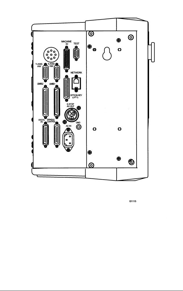
Figure 7
Pendant Cable Connections
Left Side
16
XYZ Machine Tools
ProTURN SLX 1630 ProtoTRAK SLX CNC Safety, Installation, Service & Parts List Manual
Figure 8
Pendant, Right Side
2.13 Lubrication System
2.13.1Headstock
Before turning ON the spindle, check to make sure the headstock oil reservoir is full. A site glass is located under the spindle cover. If low, fill the site level with Mobil DTE 24 or equivalent oil through the plug located on the headstock cover.
For the 1630, oil will only be visible on the headstock site glass when the spindle is running. If oil is not flowing to the site glass when the spindle is on, stop running
17
XYZ Machine Tools
ProTURN SLX 1630 ProtoTRAK SLX CNC Safety, Installation, Service & Parts List Manual

the spindle immediately and call for service. Failure to do so may ruin the spindle bearings.
2.13.2Automatic Way Lubrication Pump
The 1630 auto lube system provides centralized automatic lubrication for the carriage, cross slide and ballscrews. The lube pump has a 2-liter reservoir filled with S.A.E. 30-weight oil.
CAUTION!
Oil that is too heavy and viscous such as 50W or 90W oil can clog oil line tubing. Do not mix detergent type automotive or multi-purpose oils with the S.A.E. No. 30 lubricating oil used in this application.
The lube pump has electronic memory, which acts as an internal clock to keep track of the running time of the axis motor. Even when the axis motors are turned off, the lube pumps internal clock will not reset. The interval between pump cycles is based on axis motor movement time. Also, every time the control is first turned on, the lube pump will run for 1 lube cycle as soon as the axis motors are commanded to run.
2.13.3Lube Pump Operation
The pumping output can be regulated electronically to control the Interval Time between pumping cycles, and the Discharge Time of each pumping cycle. The pump can also be run manually through a key found under service codes. The following describes the steps used to program the lube pumps Interval and Discharge times.
Setting Interval Time: Service Code 301
Press "Mode", "Set up", "Service Codes", "E" (Lube Pump Setup), Code 301, and then enter the desired Interval time in minutes.
Setting Discharge Time: Service Code 302
Press "Mode", "Set up", "Service Codes", "E" (Lube Pump Setup), Code 302, and then enter the desired Discharge time in seconds.
To Manually Pump Oil: Service Code 300
Press "Mode", "Set up", "Service Codes", press "E", and then press Code 300 (Lubrication Pump Switch). The pump will pump oil for the amount of time programmed in Code 302. The spindle does not need to be turned on.
2.13.4Factory Default Values
Interval Time - 20 min Discharge Time - 15 sec
Discharge Pressure - Approximately 690 – 1034 kPa (100-150 PSI)
To adjust the amount of Discharge Pressure displayed on the lube pump gauge, loosen the jam nut and turn the adjustment screw located on the top right side of the lube pump while the lube pump is activated. To activate the lube pump use Service Code 300.
CAUTION!
Failure to properly lubricate the lathe will result in the premature failure of ball screws and sliding surfaces.
18
XYZ Machine Tools
ProTURN SLX 1630 ProtoTRAK SLX CNC Safety, Installation, Service & Parts List Manual

CAUTION!
Failure to manually activate the pump at the beginning of each day, or allowing the Auto Lube to run dry may cause severe damage to the 1630 lathe way surfaces and ballscrews.
The settings for the lube pump can be viewed by doing the following: press Service
Codes, press “A” (software), press Code 313. This screen lists the values programmed for the cycle time and discharge time.
19
XYZ Machine Tools
ProTURN SLX 1630 ProtoTRAK SLX CNC Safety, Installation, Service & Parts List Manual

3.0 Troubleshooting by Symptom
Electrical and Mechanical maintenance should only be carried out by trained and experienced machine tool engineers who fully understand the hazards of working with machine tools.
Use this section to begin the process of resolving a service problem. Each problem type is described in a few words and then more fully described in an explanatory paragraph. Following this is a chart that directs in the most logical steps.
3.1 Problems Relating to Machining Results
3.1.1 Poor Finish
Poor finish can be caused by a number of variables including: speeds, feeds, tooling, machine setup and chatter.
Do the following Service Codes:
Code 33 Software Identification. This is needed if you call Customer Service
Code 12 Feed Forward Constant
Code 127 Measures backlash in the system (not used on Dual Feedback systems)
Code 128 Enter backlash compensation
Possible Cause |
Check This |
|
|
Inadequate or no Lubrication to |
Make sure all the Way surfaces are getting proper |
Ballscrews and Way surfaces |
lubrication. If not, check to make sure that the lube pump |
|
is functioning properly. Also check for any pinched or |
|
blocked oil lines. |
X & Z-axis Drive Trains are loose |
Check Repeatability using the Repeatability and Positional |
|
Accuracy procedure. Step by step, carefully inspect the |
|
Drive Train for any looseness. It may be necessary to |
|
disassemble and then reassemble the Drive Train. See |
|
Mechanical Drive Train (X, Z) Section 4.2. |
Way surfaces are pocked, scarred, or |
Visually check the condition of all the Way surfaces. For |
excessively worn |
machines that may have excessively worn Way surfaces |
|
you may need to adjust the Gibs in this area. This will |
|
affect performance when using the machine outside of |
|
this area. Check lubrication to affected areas. |
Machine set-up problem |
Machine’s feet are not equally supporting weight. See |
|
Leveling, Section 2.9. |
Tooling problem |
Improper tooling, Work piece not properly supported |
|
speeds too fast, Feeds too slow. |
|
See Machine Tool & Setup, Section 4.1. |
X gib too tight or loose |
See Gib Adjustment, Section 5.2.1. |
Loose bearing problem |
Looseness in the spindle bearings. Adjust spindle preload. |
|
Ball screw misalignment, |
|
See Mechanical Drive Train (X,Z), Section 4.2. See Spindle |
|
Bearing Preload, Section 5.1.16. |
20
XYZ Machine Tools
ProTURN SLX 1630 ProtoTRAK SLX CNC Safety, Installation, Service & Parts List Manual

3.1.2 Turning Diameters Out of Round
Parts are not round within .015 mm TIR for SLX 1630. This is best measured by using a .002 mm dial indicator and mounting to the inside taper of the spindle. Rotate the spindle and measure the indicator movement.
Do the following service code and procedures:
Possible Cause |
Check This |
Tooling problem |
Improper tooling, workpiece not properly supported. |
|
See Machine Tool & Setup, Section 4.1. |
Loose bearing problem |
Looseness in the spindle bearings. See Mechanical Drive Train (X, Z), |
|
Section 4.2. Spindle bearing not preloaded correctly. Reseat bearing and |
|
preload. See Spindle Bearing Preload, Section 5.1.16. |
3.1.3 Cutting Taper
Parts are considered to be cutting on a taper if there is a difference in diameter of more than
.02 mm over 152.4 mm. This is best measured by using a .002 mm micrometer. Do the following service code and procedures:
Code 12 Determines the feed forward constant for the axis motors.
Possible Cause |
Check This |
Machine set-up problem |
Machine not leveled properly |
|
See Leveling - Section 2.9. |
Tooling problem |
Improper tooling; Work piece not properly supported. Use steady rest or |
|
follow rest, reduce overhang from chuck headstock or tailstock. |
Looseness in the gib or |
Gib adjustment. |
misalignment of ball screw |
See Gib Adjustment - Section 5.2.1. |
|
See Z Ball screw Alignment - Section 5.1.14. |
Loose bearing problem |
Looseness in the spindle bearings. |
|
See Mechanical Drive Train (X,Z) - 4.2. |
|
See Spindle Bearing Preload - Section 5.1.16. |
Headstock and/or tailstock |
See Adjust Headstock for Taper - Section 5.1.15. |
not aligned |
To adjust tailstock from side to side, adjust gib screw. See Aligning |
|
Tailstock to Spindle Section 5.1.17. |
3.1.4 Parts Have Incorrect Dimensions
Parts are being machined with dimensions that are different than those programmed. Typical accuracy expectations should be:
Parts should be round within .015 mm TIR on both the SLX 1630.
The acceptable measurement of parallelism of spindle axis to carriage movement is .02 mm over 152.4 mm.
3.1.4.1Every Part Has the Same Error
Possible Cause |
Check This |
Programming Error |
Programmed dimensions not correct. Check |
|
absolute and incremental values. |
Machine & Setup Related |
See Machine Tool & Setup - 4.1. |
3.1.4.2Errors are Random or Accumulate in Size over the Part Run
Possible Cause |
Check This |
Machining Setup |
See Machine Tool & Setup - 4.1. |
Looseness in the Drive Train, ball nut loose in |
See Mechanical Drive Train (X,Z) - 4.2. |
yoke, split nut loose, yoke loose |
|
21
XYZ Machine Tools
ProTURN SLX 1630 ProtoTRAK SLX CNC Safety, Installation, Service & Parts List Manual

3.1.5Threading Problems
Threads can be cut with an unlimited number of pitches and up to 10 leads.
To reduce the relief area when threading up to a shoulder the spindle speed should be reduced as much as possible. The slower the speed of the spindle, the closer the cutting tool can come to the end of the programmed thread before it pulls out and retracts. If a nut must be turned all the way up to a shoulder, machine a relief area behind the last thread.
NOTE: No machine can thread up to a shoulder and instantaneously pull out.
Do the following service codes and procedures:
Code 12 Determines the feed forward constant for the axis motors
Code 133 Spindle encoder test
3.1.5.1Cross Threading
Threaded parts are cross-threaded after completion of the threading event.
Possible Cause |
Check This |
Looseness in the Gib |
Gib adjustment |
|
See Gib Adjustment - Section 5.2.1. |
Looseness in the drive train |
The drive train Diagnostics |
|
See Mechanical Drive Train (X,Z) - Section 4.2. |
Calibration |
See Section 5.2.2 Calibration. |
Failure of the spindle encoder |
Replace spindle encoder |
Run service code 133 to check if the encoder |
See Spindle Encoder replacement - Section |
counts. |
5.1.10. |
3.1.5.2 |
Not Threading |
|
The machine will not cut a thread at all. |
|
|
|
|
|
|
Possible Cause |
Check This |
Spindle speed too fast |
Slow down spindle speed. |
|
Failure of the spindle encoder |
Replace spindle encoder |
|
Run service code 133 to check if the encoder |
See Spindle Encoder replacement - Section |
|
counts. |
|
5.1.10. |
Broken or slipping encoder coupling |
Check and replace as necessary |
|
3.2 Problems Regarding the Motion of the Machine
3.2.1 Run Away Axis
The axis makes an unwanted move at rapid speed in one direction and faults out. This is usually caused by an encoder signal being interrupted.
Do the following Service Codes:
Code 33 Software Identification. This is needed if you call Customer Service.
Code 100 Axis open loop test. Used to check the maximum feedrate of an axis and if the encoders are counting.
Possible Cause |
Check This |
|
|
The home positions or tools are not set |
See the Controls Programming, Operations and Care |
correctly |
manual. |
Bad Motor Encoder |
See Motor Diagnostics Section 4.4. |
22
XYZ Machine Tools
ProTURN SLX 1630 ProtoTRAK SLX CNC Safety, Installation, Service & Parts List Manual

3.2.2 Slow Down Axis
The axis slows down and moves at a feedrate that is lower than rapid or than the programmed feedrate.
Do the following Service Codes:
Code 33 Software Identification. This is needed if you call Customer Service.
Code 100 Axis open loop test. Used to check the maximum feedrate of an axis and if the encoders are counting.
Code 129 Set's the maximum allowable arc accuracy error. This applies to arcs only.
Possible Cause |
Check This |
|
|
The maximum allowable Arc Accuracy is |
This value will only slow down the machine during arc moves. |
set too low. |
The factory default is set at 0.13 mm. Perform Code 129 to |
|
check or change this value. See Service Codes Section 4.8. |
|
Values lower than 0.13 mm may reduce the feedrate even |
|
more. |
Incoming AC voltage is inadequate |
Perform Code 100. See Service Codes Section 4.8. and |
|
Electrical Section 4.6. |
Inadequate or no Lubrication to |
Make sure all the Way surfaces are getting proper lubrication. |
Ballscrews and Way surfaces |
If not, check to make sure that the lube pump is functioning |
|
properly. Also check for any pinched or blocked oil lines. See |
|
Lubrication Section 2.13. |
X-axis Gib is not adjusted properly |
Check the adjustment of the X-axis Gibs using the X-axis Gib |
|
adjustment procedures. See section 5.2.1. |
Binding in the Drive Train |
Check Repeatability using the Repeatability and Positional |
|
Accuracy procedure. Check the torque reading of the Drive |
|
Train. Step by step, carefully inspect the Drive Train for any |
|
binding. It may be necessary to disassemble and then |
|
reassemble the Drive Train. See Mechanical Drive Train (X, Z) |
|
Section 4.2. |
Servo Drive failure |
See Servo Drive Section 4.5. |
Motor failure |
See Motor Section 4.4. |
3.2.3 Axis Will Not Jog
The system powers up but will not respond to the jog command. Do the following Service Codes and procedures:
Code 33 Software Identification. This is needed if you call Customer Service.
Code 100 Axis open loop test. Used to check the maximum feedrate of an axis and if the encoders are counting.
Possible Cause |
Check This |
|
|
Improper Boot-up |
Shut down the system and wait 10 seconds before rebooting |
E-Stop is pressed in |
Check E-Stop. Especially if both axes will not jog |
E-Stop reset button |
Press the E-Stop reset button on the side of the pendant. |
Servo Drive failure |
Especially, if only one axis will not jog; |
|
See Servo Driver Section 4.5. |
Shorted motor |
See Motor Section 4.4. |
Poor cable or wiring connections |
See Cable Interconnection Section 2.12. |
Computer/Pendant failed |
See Computer/Pendant diagnostics Section 4.3. |
3.2.4 Axis Motor Motion Is Not Smooth
While under motor power, the motion is not smooth. The motion appears to be "rough" or jerky”.
Do the following Service Codes and procedures:
23
XYZ Machine Tools
ProTURN SLX 1630 ProtoTRAK SLX CNC Safety, Installation, Service & Parts List Manual

Code 33 Software Identification. This is needed if you call Customer Service.
Code 12 Feed Forward Constant
Code 127 Measure's the backlash in the system
Code 128 Enter backlash compensation
Code 100 Axis open loop test. Used to check the maximum feedrate of an axis and if the encoders are counting
Possible Cause |
Check This |
|
|
X-axis Gib are not adjusted |
Check the adjustment of the X-axis Gib using the X-axis Gib |
properly |
adjustment procedures, See Section 5.2.1.. |
Calibration or Backlash problem |
Recalibrate the machine. Reset the Backlash. Check |
|
Repeatability and Positional Accuracy. See Calibration & |
|
Backlash Constants section 5.2.2. |
Binding in the Drive Train |
Check Repeatability using the Repeatability and Positional |
|
Accuracy procedure. Check the torque reading of the Drive |
|
Train. Step by step, carefully inspect the Drive Train for any |
|
binding. It may be necessary to disassemble and then |
|
reassemble the Drive Train. See Mechanical Drive Train (X, Z) |
|
Section 4.2. |
3.2.5 Vibration in Motion
While axis is moving there is vibration or noise coming from the X or Z-axis. Do the following Service Codes and procedures:
Code 12 Feed Forward Constant
Code 127 Measure's the backlash in the system.
Code 128 Enter backlash compensation
Possible Cause |
Check This |
|
|
Too much backlash entered in Code 128. |
Recheck the machines backlash. See Section 5.2.2. |
Inadequate or no Lubrication to |
Make sure all the Way surfaces are getting proper lubrication. |
Ballscrews and Way surfaces |
If not, check to make sure that the lube pump is functioning |
|
properly. Also check for any pinched or blocked oil lines. See |
|
Lubrication Section 2.13. |
X Gib not making good contact. |
Pull gibs out and mark with a blue die to check where the gibs |
|
are making contact. It is recommended that the gibs |
|
uniformly contact at least 80% of the surface. See Section |
|
5.2.1 Crosslide gib adjustment. |
Binding or looseness in the Drive Train |
Check Repeatability using the Repeatability and Positional |
|
Accuracy procedure. Check the torque reading of the Drive |
|
Train. Step by step, carefully inspect the Drive Train for any |
|
binding or looseness. It may be necessary to disassemble and |
|
then reassemble the Drive Train. See Mechanical Drive Train |
|
(X, Z) Section 4.2. |
Axis Motor belt too tight. |
Loosen belt. |
Misalignment of ball screw |
See Mechanical Drive Train (X, Z) Section 4.2. |
3.2.6 Searching Axis
The ballscrews are slowly turning back and forth when the servos are engaged. Do the following Service Code and procedures:
Code 12 Sets a feed forward power constant to drive axis motors.
Code 128 Backlash compensation on single feedback machines.
24
XYZ Machine Tools
ProTURN SLX 1630 ProtoTRAK SLX CNC Safety, Installation, Service & Parts List Manual
Possible Cause |
Check This |
|
|
Most often causes by excess backlash |
Check physical backlash in system and re-enter in code 128. |
compensation |
Run code 11 on single feedback machines |
High feed forward values |
Check ball screw torque. Typical values should be between 1.1 |
|
– 1.7 N-m. |
Excessive friction in the sliding ways |
Lubrication, gib adjustments, gib locks. |
|
See Machine Tool & Setup - Section 4.1. |
Looseness in the drive train |
The drive train of the axis that is searching, especially the |
|
tightness of the drive assembly. |
|
See Mechanical Drive Train (X, Y) - Section 4.2. |
3.3 Problems Relating to the Operation of the Control
3.3.1 Display Blanks
The display is completely blank.
Possible Cause |
Check This |
|
|
Screen saver has been activated |
Press any key to turn back on. All LED keys on pendant will |
|
blink when the screen saver is on. Press any key to deactivate. |
|
Hitting this key will not activate any feature on the control. |
The system has shut down |
Turn the power switch off, check the computer/ |
|
pendant fuses and cable connections. See Electrical Section 4.6. |
Poor cable connection from Computer |
Double-check the connection from the computer module to the |
Module to LCD (Liquid Crystal Display) |
LCD, see Section 5.1.3. |
Fuse blown in pendant |
Remove fuse and check continuity |
Computer/Pendant failed |
See Computer/Pendant Section 4.3. |
3.3.2 Bad Picture on the Display
The display has strange characters, horizontal bars or other unfamiliar images, or the display continually rolls.
Possible Cause |
Check This |
|
|
Poor cable connection from Computer |
Check the ribbon cable connection from the LCD screen |
Module to LCD (Liquid Crystal Display) |
to the computer module . See Section 5.1.3. |
Computer/Pendant failed |
See Computer/Pendant Section 4.3. |
3.3.3 Keyboard Lockup
The screen display is normal, but the system will not respond to key presses. Do the following Service Codes and procedures:
Code 81 press each key on the pendant. The screen will display a keypad that signifies if a key is working. The pendant will also beep.
|
Possible Cause |
Check This |
|
|
|
|
|
|
Voltage drop/spike has occurred |
Shut down the system and wait 10 seconds to reboot the |
|
|
|
system. |
|
|
Remote Stop-Go (RSG) switch has a |
Remove the RSG. Turn the system off and then on again. |
|
|
short (if connected) |
If the problem goes away and then re-appears when the |
|
|
|
RSG is plugged-in, replace the RSG. |
|
|
Poor cable connections from the |
Re-seat cable connectors by pulling out and pushing back |
|
|
Computer Module to the Distribution |
in. |
|
|
Board and from the Distribution Board |
|
|
|
to the Keyboard |
|
|
|
Computer/Pendant failed |
See Computer/Pendant Section 4.3. |
|
|
|
25 |
|
|
|
XYZ Machine Tools |
|
ProTURN SLX 1630 ProtoTRAK SLX CNC Safety, Installation, Service & Parts List Manual

3.3.4 Fault X or Z
The program run or jogging operation is interrupted with a Fault Message on the display.
Do the following Service Codes and procedures:
Code 33 Software Identification. This is needed if you call Customer Service.
Code 12 Feed Forward Constant.
Code 100 Axis open loop test. Used to check the maximum feedrate of an axis and if the encoders are counting.
Possible Cause |
Check This |
|
|
Servo cables at pendant switched around. |
Make sure during an installation the X and Z servo |
|
cables at the pendant are in the correct ports. |
X-axis Gibs are adjusted extremely tight |
Check the adjustment of the X-axis Gibs using the X |
|
Gib adjustment procedures. See X-axis Gib |
|
Adjustments Section 5.2.1. |
Excessive friction in the slideways |
See Machine Tool & Setup Section 4.1. |
Binding or looseness in the Drive Train |
See Mechanical Drive Train (X, Z) Section 4.2. |
Incoming electrical power |
Incoming voltage. See Electrical Section 2.10. |
Servo Drive failure |
See Servo Driver - Section 4.5. |
Motor failure |
See Motor diagnostics, Section 4.4. |
Computer/Pendant failure |
See Computer/Pendant diagnostics, Section 4.3. |
3.3.5Problems Reading the Floppy Disk; Programs Not Saved Properly
The floppy drive will not read or write programs from a disk.
Possible Cause |
Check This |
|
|
Improper Boot-up |
Shut down the system and wait 10 seconds before |
|
rebooting. |
Floppy Disk failure |
The Floppy Disk may be bad. See if the Floppy Disk |
|
can be read by a Personal Computer. Does the green |
|
light on the floppy drive come on when you access the |
|
disk? If so, power is getting to the floppy drive. If |
|
not check connections of floppy drive inside the |
|
computer module. See Computer/Pendant Section 4.3 |
|
for more information. |
Floppy Disk full |
Put the Floppy Disk into a Personal Computer to see |
|
how many bytes remain. |
3.3.6 System Will Not Turn On
Nothing happens when the switch is turned on.
Possible Cause |
Check This |
|
|
110 V line is not plugged in |
Check incoming 110 V power source to electrical cabinet |
Pendant On/Off switch is Off. |
Check the Pendant On/Off switch |
Fuse blown in pendant or electrical |
Remove fuses and check continuity. |
cabinet |
|
Transformer output |
Check 110 V Transformer output |
Computer/Pendant has failed |
See Computer/Pendant diagnostics Section 4.3. |
3.3.7 System Will Not Boot-Up
The system does not boot-up when the switch is turned on.
26
XYZ Machine Tools
ProTURN SLX 1630 ProtoTRAK SLX CNC Safety, Installation, Service & Parts List Manual
 Loading...