


TRAK® EMX KNEE & BED MILLS
ProtoTRAK® EMX CNC
Service, Safety, Installation, Maintenance, & Parts
Document: P/N 26109
Version: 100713
Covers Models:
ProtoTRAK EMX Retrofits
TRAK KEMX Knee Mill
TRAK K3 EMX Knee Mill
TRAK K4 EMX Knee Mill
TRAK DPM EX2 Bed Mill
Southwestern Industries, Inc.
2615 Homestead Place
Rancho Dominguez, CA 90220-5610 USA T | 800.421.6875 | F | 310. 764.2668
Service Department: 800.367.3165
e-mail: sales@southwesternindustries.com | service@southwesternindustries.com | web: southwesternindustries.com
Copyright © 2013, Southwestern Industries, Inc. All rights are reserved. No part of this publication may be reproduced, stored in a retrieval system, or transmitted, in any form or by any means, mechanical, photocopying, recording or otherwise, without the prior written permission of Southwestern Industries, Inc.
While every effort has been made to include all the information required for the purposes of this guide, Southwestern Industries, Inc. assumes no responsibility for inaccuracies or omission and accepts no liability for damages resulting from the use of the information contained in this guide.
All brand names and products are trademarks or registered trademarks of their respective holders.

Table of Contents
1.0Safety
1.1 |
Safety Publications |
1 |
1.2Danger, Warning, Caution & Note Labels & Notices as used in this Manual
1.3Safety Precautions
2.0Installation
2.1 |
Floor Plan, Layout & Space Requirements |
6 |
2.2Uncrating
2.3Shortages: Inventory Checklist
2.4Installation Instructions & Checklist
2.5Machine Specifications
2.6Maximum Work Capacities
2.7ProtoTRAK EMX Control Hardware
2.8Lifting and/or Moving the Machine
2.8.1Releasing the Head Counterweight
Support
2.9Cleaning
2.10Leveling: Leveling Tolerance is .0005”/10”
2.11Pendant Connections
2.12Electrical Connection
2.13Air Connection (Optional)
2.14Lubrication
2.14.1Manual Lubrication – KEMX
2.14.2Auto Lubrication – DPMEX2
2.14.3Head Lubrication
3.0ProtoTRAK EMX Retrofit Installation
3.1 |
Recommended Tools |
29 |
3.2Kit Parts
3.2.1Ballscews
3.2.2Pendant Arm Assembly
3.2.3Motors
3.2.4Options
3.2.5Pendant & Pendant Hardware
3.2.6X Axis Drive Kit
3.2.7Y Axis Drive Kit
3.2.8Yoke Kit
3.2.9Other Parts
3.3Installation Steps
Step 1: Remove the table and lead screws Step 2: Install the X (Table) Ballscrew Step 3: Install the Y (Saddle) Ballscrew Step 4: Install the Y Axis Drive Train
Step 5: Replace the table and install the X Drive Train (Left Side) Motor
Step 6: Install the Right Side End Cap and Handwheel Assembly
Step 7: Install the Display Pendant Step 8: Install the Z Glass Scale
Step 9: Connect the Cables and the Power Step 10: Check Out
4.0Troubleshooting by Symptom
4.1 |
Problems Relating to Machining Results |
68 |
4.1.1Poor Finish
4.1.2Circles Out of Round
4.1.3Taper Cut on a Programmed Straight Line Move
4.1.4Parts Have Incorrect Dimensions
4.2Problems Regarding the Motion of the Machine
4.2.1Run Away Axis
4.2.2Slow Down Axis
4.2.3Axis Will Not Jog
4.2.4Axis Motor Motion is Not Smooth
4.2.5Searching Axis
4.3Problems Relation to the Operation of the Control
4.3.1Display Blanks
4.3.2Bad Picture on the Display
4.3.3Keyboard Lockup
4.3.4Fault X or Y
4.3.5System Will Not Turn On
4.3.6System Reboots by Itself
4.3.7System Shuts Off
4.3.8Will Not Hold Calibration
4.3.9E-Stop Error
4.4Problem with the Measurements
4.4.1X, Y & Z-Axis Measurements Do Not Repeat
4.4.2X, Y & Z-Axis Measurements Are Not Accurate
4.4.3The DRO is Not Counting
4.4.4X, Y, & Z-Axis DRO Counting In Wrong Direction
4.5Problems with the Machine Tool
4.5.1Spindle Stalls or Turns Off
4.5.2Spindle Motor Hums or Will Not Run
4.5.3Spindle Runs Backwards
4.5.4Head Noise
5.0Diagnostics
5.1 |
The Machine Tool & Set-Up |
80 |
5.1.1The Milling Machine Checklist
5.1.2A Special Word About X & Y Gibs
5.1.3Lubrication
5.1.4Machining Set-Up
5.2The Mechanical Drive Train (X, Y)
5.2.1Keys to Ballscrew Alignment
5.3Computer/Pendant Diagnostics
5.4Motor Diagnostics
5.4.1Cable Connections
5.4.2To Check Motor Encoders
5.4.3Diagnosing a Brush Problem
1
Southwestern Industries
ProtoTRAK K EMX, DPMEX2 & Retrofit Safety, Installation, Maintenance, Service & Parts List Manual

5.4.4Moving Problem from One Axis To Another
5.5Servo Driver
5.6Electrical
5.6.1Checking A/C Voltage
5.6.2Checking Fuses
5.6.3Cable Connections
5.7Service Codes
5.7.1Software Codes
5.7.2Machine Set-Up Codes
5.7.3Diagnostic Codes
5.7.4Operator Defaults/Options Codes
6.0Procedures for Replacements &
Maintenance
6.1 Replacements 97
6.1.1Servo Motor Replacement
6.1.2Motor Brush Replacement
6.1.3Servo Driver Replacement
6.1.4Computer Module Replacement
6.1.5IDE Flash Disk Replacement
6.1.6Cable Routing on Machine
6.1.7Replacement Z Axis Scale, Mill Only
6.1.8Power Drawbar
6.1.9Ball Screw Replacement, X-Axis
6.1.10Ball Screw Replacement, Y-Axis 6.1.10.1 Ball Screw Replacement, Z-Axis
6.1.11Spindle Motor Wiring
6.1.12Feed Trip Adjustment
6.1.13Quill Clock Spring Replacement & Adjustment
6.1.14Spindle Motor Removal & Replacement
6.1.15Drive Belt Replacement
6.1.16Timing Belt Replacement
6.1.17Brake Shoe Replacement
6.1.18Spindle Replacement
6.2Maintenance
6.2.1Gib Adjustments
6.2.2Calibration & Backlash Constants
6.2.3Head Rotational and Tramming
Figures found in Section 7.0 |
128 |
|
Fig. 100 Top Housing Assembly, K4 |
|
|
Fig. 101 Gear Housing Sub-Assembly, K4 |
|
|
Fig. 102 Hi-Low Slip Clutch Sub-Assembly, K4 |
|
|
Fig. 103 Hi-Low Shift Sub-Assembly, K4 |
|
|
Fig. 104 Pulley Pinion Sub-Assembly, K4 |
|
|
Fig. 105 Lower Vari-Disc Sub-Assembly, K4 |
|
|
Fig. 106 Upper Vari-Disk Sub Assembly, K4 |
|
|
Fig. 107 Speed Change Handwheel Sub-Assembly |
|
|
Fig. 108 Spindle Motor Sub Assembly, K4 |
|
|
Fig. 109 Bottom Housing Assembly, K4 |
|
|
Fig. 110 |
Worm Gear Cradle Sub-Assembly, K4 |
|
Fig. 111 |
Quill Feed Selector Sub-Assembly, K4 |
|
Fig. 112 |
Quill Pinion Shaft Sub-Assembly, K4 |
|
Fig. 113 |
Overload Clutch Trip Sub-Assembly, K4 |
|
Fig. 114 Feed Reverse Clutch Sub-Assembly, K4 Fig. 115 Spindle Sub-Assembly, K4
Fig. 118 Top Housing Assembly, K2/K3
Fig. 119 Gear Housing Sub-Assembly, K2/K3
Fig. 120 Hi-Low Shift Clutch Sub-Assembly, K2/K3 Fig. 121 Hi-Low Shift Sub-Assembly, K2/K3
Fig. 122 Pulley Pinion Sub-Assembly, K2/K3 Fig. 123 Lower Vari-Disc Drive Sub-Assembly,
K2/K3
Fig. 124 Upper Vari-Disc Drive Sub-Assembly, K2/K3
Fig. 125 Speed Change Handwheel Sub-Assembly, K2/K3
Fig. 126 Spindle Motor Sub-Assembly, K2/K3 Fig. 127 Bottom Housing Assembly, K2/K3
Fig. 128 Worm Gear Cradle Sub-Assembly, K2/K3 Fig. 129 Quill Feed Selector Sub-Assembly, K2/K3 Fig. 130 Quill Pinion Shaft Sub-Assembly, K2/K3 Fig. 131 Overload Clutch Trip Sub-Assembly, K2/K3 Fig. 132 Feed Reverse Clutch Sub-Assembly, K2/K3 Fig. 133 Spindle Sub-Assembly, K2/K3
Fig. 134 K2/K3 Base Machine Fig. 135 K4 Base Machine Fig. 136 KE Base Machine
2
Southwestern Industries
ProtoTRAK K EMX, DPMEX2 & Retrofit Safety, Installation, Maintenance, Service & Parts List Manual
1.0 Safety
The safe operation of the TRAK Mills and the ProtoTRAK CNC depends on their proper use and the precautions taken by each operator.
Read and study this manual and the ProtoTRAK EMX Programming, Operating, and Care Manual. Be certain every operator understands the operation and safety requirements of this machine before its use.
Always wear safety glasses and safety shoes.
Always stop the spindle and check to ensure the CNC control is in the stop mode before changing or adjusting the tool or workpiece.
Never wear gloves, rings, watches, long sleeves, neckties, jewelry, or other loose items when operating or around the machine.
Use adequate point of operation safeguarding. It is the responsibility of the employer to provide and ensure point of operation safeguarding per OSHA 1910.212 - Milling Machine.
1.1Safety Publications
Refer to and study the following publications for assistance in enhancing the safe use of this machine.
Safety Requirements for Manual Milling, Drilling and Boring Machines with or without Automatic Control (ANSI B11.8-2001). Available from The American National Standards Institute, 1819 L Street N.W., Washington D.C. 20036
Concepts And Techniques Of Machine Safeguarding (OSHA Publication Number 3067). Available from The Publication Office - O.S.H.A., U.S. Department of Labor, 200 Constitution Avenue, NW, Washington, DC 20210.
1.2 Danger, Warning, Caution, and Note Labels & Notices As Used In This Manual
DANGER - Immediate hazards that will result in severe personal injury or death. Danger labels on the machine are red in color.
WARNING - Hazards or unsafe practices which could result in severe personal injury and/or damage to the equipment. Warning labels on the machine are orange in color.
CAUTION - Hazards or unsafe practices, which could result in minor personal injury or equipment/product damage. Caution labels on the machine are yellow in color.
NOTE - Call attention to specific issues requiring special attention or understanding.
1
Southwestern Industries, Inc.
ProtoTRAK K EMX, DPMEX2 & Retrofit Safety, Installation, Maintenance, Service & Parts List Manual

Safety & Information Labels Used On The
TRAK Milling Machines
It is forbidden by OSHA regulations and by law to deface, destroy or remove any of these labels
2
Southwestern Industries, Inc.
ProtoTRAK K EMX, DPMEX2 & Retrofit Safety, Installation, Maintenance, Service & Parts List Manual

Safety & Information Labels Used On TRAK Milling Machines
It is forbidden by OSHA regulations and by law to deface, destroy or remove any of these labels
Power Requirements at 220 and 440 Volts, 3-phase 60 Hz
|
KEMX & DPMEX2 |
|
|
Overload Setting 220 V |
8.5 A |
Overload Setting 440 V |
4.25 A |
FLA of Largest Motor at 220 V |
8.5 A |
FLA of Largest Motor at 440 V |
4.25 A |
FLA of Machine at 220 V |
8.5 A |
FLA of Machine at 440 V |
4.25 A |
3
Southwestern Industries, Inc.
ProtoTRAK K EMX, DPMEX2 & Retrofit Safety, Installation, Maintenance, Service & Parts List Manual

1.3Safety Precautions
1.Do not operate this machine before the TRAK Mill Installation, Maintenance, Service and Parts List Manual, and ProtoTRAK EMX Programming, Operating & Care Manual have been studied and understood.
2.Do not run this machine without knowing the function of every control key, button, knob, or handle. Ask your supervisor or a qualified instructor for help when needed.
3.Protect your eyes. Wear approved safety glasses (with side shields) at all times.
4.Don't get caught in moving parts. Before operating this machine remove all jewelry including watches and rings, neckties, and any loose-fitting clothing.
5.Keep your hair away from moving parts. Wear adequate safety headgear.
6.Protect your feet. Wear safety shoes with oil-resistant, anti-skid soles, and steel toes.
7.Take off gloves before you start the machine. Gloves are easily caught in moving parts.
8.Remove all tools (wrenches, chuck keys, etc.) from the machine before you start. Loose items can become dangerous flying projectiles.
9.Never operate a milling machine after consuming alcoholic beverages, or taking strong medication, or while using non-prescription drugs.
10.Protect your hands. Stop the machine spindle and ensure that the CNC control is in the stop mode:
Before changing tools
Before changing parts
Before you clear away the chips, oil or coolant. Always use a chip scraper or brush
Before you make an adjustment to the part, fixture, coolant nozzle or take measurements
Before you open safeguards (protective shields, etc.). Never reach for the part, tool, or fixture around a safeguard.
11.Protect your eyes and the machine as well. Don't use compressed air to remove the chips or clean the machine.
12.Disconnect power to the machine before you change belts, pulley, and gears.
13.Keep work areas well lighted. Ask for additional light if needed.
14.Do not lean on the machine while it is running.
15.Prevent slippage. Keep the work area dry and clean. Remove the chips, oil, coolant and obstacles of any kind around the machine.
16.Avoid getting pinched in places where the table, saddle or spindle head create "pinch points" while in motion.
17.Securely clamp and properly locate the workpiece in the vise, on the table, or in the fixture. Use stop blocks to prevent objects from flying loose. Use proper holding clamping attachments and position them clear of the tool path.
4
Southwestern Industries, Inc.
ProtoTRAK K EMX, DPMEX2 & Retrofit Safety, Installation, Maintenance, Service & Parts List Manual

18.Use correct cutting parameters (speed, feed, depth, and width of cut) in order to prevent tool breakage.
19.Use proper cutting tools for the job. Pay attention to the rotation of the spindle: Left hand tool for counterclockwise rotation of spindle, and right hand tool for clockwise rotation of spindle.
20.After an emergency stop, always turn the FORWARD/REVERSE switch to "Off" (STOP) before releasing or resetting the E-Stop.
21.Prevent damage to the workpiece or the cutting tool. Never start the machine (including the rotation of the spindle) if the tool is in contact with the part.
22.Check the direction (+ or -) of movement of the table, saddle and ram when using the jog or power feed.
23.Don't use dull or damaged cutting tools. They break easily and become airborne. Inspect the sharpness of the edges, and the integrity of cutting tools and their holders. Use proper length for the tool.
24.Large overhang on cutting tools when not required result in accidents and damaged parts.
25.Handwheels must have the crank folded inside when using CNC programmed machining or rapid feeds, power feed or jog.
26.Prevent fires. When machining certain materials (magnesium, etc.) the chips and dust are highly flammable. Obtain special instruction from you supervisor before machining these materials. Keep flammable materials and fluids away from the machine and hot, flying chips.
27.Changing the speed of rotation of the spindle must be done while the rotation is on. It is recommended to stop and start the spindle at a low rate of speed.
28.Interlocked table guards may be purchased from Southwestern Industries, Inc., if deemed necessary by the user.
5
Southwestern Industries, Inc.
ProtoTRAK K EMX, DPMEX2 & Retrofit Safety, Installation, Maintenance, Service & Parts List Manual

2.0 Machine Installation
Read and understand this entire installation section before beginning the installation procedure.
2.1 Floor Plan, Layout & Space Requirements
Figure 1 - KEMX - Machine Footprints
KEMX
Weight (approximate) net |
2800 lbs |
|
Weight (approximate) shipping |
3100 lbs |
|
Pallet Size |
6’ x 6’ |
|
A |
Overall width |
103” |
B |
Overall length |
70” |
C |
Base width |
24.2” |
D |
Width between leveling screws |
21.9” |
E |
Distance between leveling screws |
29.7” |
F |
Base length |
38.8” |
6
Southwestern Industries, Inc.
ProtoTRAK KEMX, DPMEX2 & Retrofit Safety, Installation, Maintenance, Service & Parts List Manual
Figure 2 - KEMX - Overall Dimensions
KEMX
Table Size |
10” x 50” |
Dimension G |
87” |
Dimension G Min |
65” |
Dimension H Min |
64” |
Dimension H Max |
78” |
Dimension I Min |
38” |
Dimension I Max |
49’ |
Dimension J Max |
17” |
7
Southwestern Industries, Inc.
ProtoTRAK KEMX, DPMEX2 & Retrofit Safety, Installation, Maintenance, Service & Parts List Manual

Floor Plan, Layout & Space Requirements – DPMEX2
Figure 2.1 - DPMEX2 - Machine Footprints
DPMEX2
Footprint of Machine |
23.1” x 40.5” |
|
Weight (approximate) net |
3200 lbs. |
|
Weight (approximate) shipping |
3500 lbs. |
|
Pallet Size |
70” x 70” |
|
A |
Overall width |
101” |
B Overall length w/ electric box door open |
72” |
|
C |
Bed width |
23.125” |
D Bed width between leveling screws |
20.5” |
|
E Distance between leveling screws |
32.5” |
|
F |
Bed length |
40.5” |
8
Southwestern Industries, Inc.
ProtoTRAK KEMX, DPMEX2 & Retrofit Safety, Installation, Maintenance, Service & Parts List Manual

Figure 2.2 - Overall Dimensions
DPMEX2
G |
Height of table from bottom of bed |
34” |
H |
Maximum distance from spindle nose to table |
23.5” |
I |
Maximum height of machine from bottom of bed to top of column cover. |
78” |
J |
Height of machine from bottom of bed to top of spindle motor |
89” |
K |
Width of machine including table |
70” |
L |
Length of machine with electric box door closed |
64” |
2.2 Uncrating
Carefully remove the wood crate and protective packaging, paying attention not to scratch, damage, or mar any parts of the machine.
Remove the cardboard box containing the TOOL BOX. The leveling pads and screws for the machine can be found in the toolbox. The Y way covers are shipped in a separate tube.
Loosen and remove 4 screws and nuts holding the machine to the wood pallet.
9
Southwestern Industries, Inc.
ProtoTRAK KEMX, DPMEX2 & Retrofit Safety, Installation, Maintenance, Service & Parts List Manual

2.3 Shortages: Inventory Checklist
_____ Machine (check model and serial number)
______ Manual drawbar with washer
______ Leveling pads (B239) and screws (B240) (4 each)
______ Pendant Display (installed on machine)
______ Pendant Arm assembled to the column
______ Toolbox with various tools
______ ProtoTRAK EMX Safety, Operation & Programming Manual (P/N 26056)
______ TRAK KEMX & Retrofit Safety, Installation, Maintenance, Service & Parts List Manual (P/N 26109)
______ Way covers – front & rear of saddle
______ Way covers DPMEX2 – front (23676) and rear (23677) of saddle
______ Way covers DPMEX2 - bottom on column (23675), top on column (23675)
10
Southwestern Industries, Inc.
ProtoTRAK KEMX, DPMEX2 & Retrofit Safety, Installation, Maintenance, Service & Parts List Manual

2.4 Installation Instructions & Checklist
Installer: Use this checklist to assure a complete set-up of the KE, DPMEX2 or EMX retrofit.
1. Shut off power to the machine.
2. Visually inspect the 220 or 440V wiring going into the electrical panel. Visually verify the wiring is correct per our wiring diagram. Make sure a strain relief is being used where the wiring enters the cabinet.
3. Use a 10mm socket to turn the Z-axis ball screw at the top of the column in order to lower the head until the counterweight is raised off of the counterweight support rods. (DPMEX2 only)
4. Remove the 2 bottom head supports and also remove the 2 zip ties from the counterweight chain. DPMEX2 only.
5. Remove the two (2) counterweight support rods.
6. Clean the machine if needed and remove any remaining grease.
7. Unlock the table, saddle, knee or column gib locks.
8. Make and check all the proper electrical connections from the pendant to the electric box. See the pendant and electric box wiring diagrams.
9. Turn on the power to the machine and to the pendant.
10. Lubricate all the way surfaces and the ball screws.
11. Jog the table and saddle or Z axis back and forth until the way surfaces are well lubricated. Oil should be visible on all the way surfaces.
12. Check the level of the machine. The machine should be level to within 0.0005" front to back and 0.0005" side to side.
13. Check to make sure that the E-Stop button is functioning correctly.
14. Perform Service Code 12, Feed Forward Constant.
15. Perform Service Code 123 to calibrate the X and Y-axis using a 150mm standard.
16. Perform Service Code 127 and 128 to manually calculate the backlash for the X and Y-axis.
17. Assure the Z-axis quill glass scale is working and the Z axis DRO is functioning. Use Service Code 15 to turn on the Z axis readout. (Z axis quill scale is optional, knee mills only.)
18. Perform Service Code 123 and press QUILL softkey to calibrate the Z-axis quill using a 75mm standard. For bed mill, calibrate the Z axis with the 75 mm standard.
19. Perform Service Code 100 in both directions for the X, Y and/or Z-axes, to verify that the feed rate shown on the display is at least 120 ipm.
20. Run the spindle at various speeds in both high and low gear for 15 minutes. Verify head shifts from high to low gear smoothly. Test quill feed and spindle brake. N/A to retrofits.
21. Install the Y-axis front and rear way covers.
22. Install the top and bottom column way covers. Bed mill only.
23. If the machine has a power drawbar option, check to make sure that the tools load and unload properly. N/A to retrofits.
24. Wipe down the machine.
11
Southwestern Industries, Inc.
ProtoTRAK KEMX, DPMEX2 & Retrofit Safety, Installation, Maintenance, Service & Parts List Manual

2.5 |
Machine Specifications |
|
|
|
|
|
|
||
|
|
|
|
|
|
|
|
|
|
|
|
|
|
|
KEMX |
|
DPMEX2 |
||
|
Table size |
|
|
50” x 10” |
|
49” x 9” |
|||
|
Movement and ranges (X, Y, Z axis) |
|
32” x 16” x 16” |
|
31 x 16 x 23.5” |
||||
|
Quill Travel (maximum) |
|
|
5” |
|
5” |
|||
|
Quill Diameter |
|
|
86 mm |
|
86 mm |
|||
|
Spindle Taper |
|
|
R8 |
|
R8 |
|||
|
Speed Range |
|
60-4200 RPM |
|
60-4200 RPM |
||||
|
Spindle to Column |
|
|
8” to 32” |
|
18” |
|||
|
Quill Feeds Per Revolution of Spindle |
|
.0015/.003/.006” |
|
.0015/.003/.006” |
||||
|
Head Tilt |
|
|
+/- 90 |
|
+/- 90 |
|||
|
Head Swivel |
|
|
+/- 45 |
|
n/a |
|||
|
Spindle Motor Power |
|
|
3 HP |
|
3 HP |
|||
|
Voltage |
|
220/440 V |
|
220/440 V |
||||
|
Phase/Cycle |
|
3 phase/60 Hz |
|
3 phase/60 Hz |
||||
|
Current |
|
8.5/4.3 amps |
|
8.5/4.3 amps |
||||
|
Maximum Weight of Workpiece |
|
|
850 lbs |
|
1320 lbs |
|||
2.6 |
Maximum Work Capacities |
|
|
|
|
|
|
||
|
|
|
|
|
|
||||
|
|
Drilling Mild Steel (2-axis manual feed) |
|
1 ¼” |
|
||||
|
|
|
|
|
|
|
|
|
|
|
|
Tapping Mild Steel |
|
|
|
|
1” |
|
|
|
|
Milling (metal removal rate/mild steel) |
|
1 ½ inch3/min |
|
||||
Maximum work capacities are dependent on a lot of variables that cannot be controlled by the machine manufacturer. Each one of the following will have an impact on the above numbers: speeds, feeds, cutter, cutter sharpness, material, setup, coolant and machine adjustments. The numbers above assume all conditions are optimal and may be higher or lower depending on material composition.
2.7ProtoTRAK EMX Control Hardware
Digital Servo Amplifiers – custom designed for ProtoTRAK operation
D.C. Servo Motors – rated at 280 in-oz. continuous torque are twice that required
Precision Ball Screws – in the table and saddle
Modular Design – simplifies service and maximized uptime
115V/60HZ/10 amps
Feedrate Override of programmed feedrate and rapid
Polycarbonate Sealed Membrane Keypad to lock out contamination
7.0” Color LCD
On board IDE flash memory storage for part programs
USB port for interface with a storage device
Rugged Industrial PC
Glass Scale on quill for Z-axis readout (Optional on knee mill)
12
Southwestern Industries, Inc.
ProtoTRAK KEMX, DPMEX2 & Retrofit Safety, Installation, Maintenance, Service & Parts List Manual
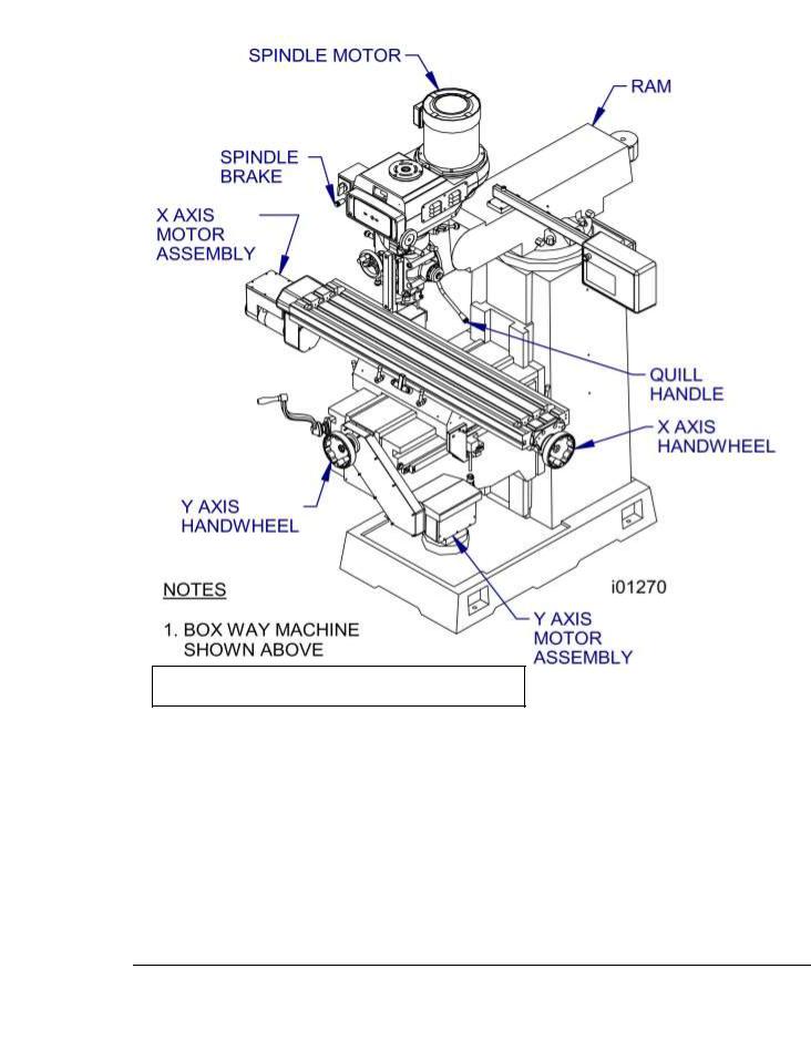
2. OPTIONAL QUILL SCALE SHOWN ABOVE
Figure 3 & Parts List Shown - Knee Mill Component Identification
Part Number |
Description |
20819 |
Spindle Motor |
26015-1 |
EMX Pendant |
26015-7 |
EMX Pendant 3 |
15616 |
Y Axis Handwheel (Saddle) |
15616 |
X Axis Handwheel (Table) |
20296 |
X Axis Motor |
20296-1 |
Y Axis Motor |
13
Southwestern Industries, Inc.
ProtoTRAK KEMX, DPMEX2 & Retrofit Safety, Installation, Maintenance, Service & Parts List Manual

Figure 4 & Parts List Shown - Knee Mill Rear View
Part Number |
Description |
|
|
220V=20676 |
**Electrical Box – used on knee and bed mills |
440V=20676 |
|
9001 |
Lube Pump |
If the machine was sold with a table guard option, the electrical box part number is 20676-2.
14
Southwestern Industries, Inc.
ProtoTRAK KEMX, DPMEX2 & Retrofit Safety, Installation, Maintenance, Service & Parts List Manual

Figure 4.1 & Parts List Shown - DPMEX2 - Component
Identification
Item |
Part Number |
Description |
|
|
|
|
|
1 |
20819-1 |
Spindle Motor |
|
2 |
26015-7 |
EMX Pendant – 2 ½ axis |
|
3 |
15616 |
Y-Axis Handwheel (Saddle) |
|
4 |
15616 |
X-Axis Handwheel (Table) |
|
5 |
21157-1 |
Lube Pump |
|
6 |
20296 |
X & Z Axis Motor |
|
20296-1 |
Y Axis Motor |
||
|
15
Southwestern Industries, Inc.
ProtoTRAK KEMX, DPMEX2 & Retrofit Safety, Installation, Maintenance, Service & Parts List Manual

2.8 Lifting and/or Moving the Machine - KEMX
CAUTION!
The K machine weighs approximately 2800 lbs. Proper equipment of sufficient capacity must be used when lifting and/or moving the machine.
(See Figure 5 To Prepare the Mill before Lifting):
1.Using a steel cable with protective sleeving (min 3/4” diameter) or a 3-ton sling, position sling loops on machine as shown in Figure 5.
2.Use cardboard pieces or other suitable protective sheets on both sides of the machine to prevent scratching.
3.Remove the 4 nuts and screws holding the machine to the wood skid.
4.Lift the machine (the machine should lift approximately level).
5.Insert the 4 screws for leveling pads in their place in the bed.
6.Place the machine in its location (see floor plan and bed footprint drawing). Carefully positioning each leveling pad under each leveling screw.
7.Remove the lifting cable or sling and all protective cardboard.
16
Southwestern Industries, Inc.
ProtoTRAK KEMX, DPMEX2 & Retrofit Safety, Installation, Maintenance, Service & Parts List Manual
Figure 5 - Lifting the Machine
17
Southwestern Industries, Inc.
ProtoTRAK KEMX, DPMEX2 & Retrofit Safety, Installation, Maintenance, Service & Parts List Manual

Lifting and/or Moving the Machine – DPMEX2
CAUTION!
The DPMEX2 machines weigh approximately 3200 lbs. Proper equipment of sufficient capacity must be used when lifting and/or moving the machine.
Method 1 (see Figure 5.1):
1.Insert a steel bar 1.0" dia x 36" long through the rear side holes of the bed (under column).
2.Use a steel cable (with protective sleeving) min. 3/4" dia. or a 3 ton sling.
3.Use cardboard pieces or other suitable protective sheets on both sides of the machine to prevent scratching.
4.Remove the 4 nuts and screws holding the machine to the wood skid.
5.Lift the machine (the front side of the machine should be lower than the back side).
6.Insert the 6 screws for leveling pads in their place in the bed. 4 screws for DPMEX2.
7.Place the machine in its location (see floor plan and bed footprint drawing) carefully positioning each leveling pad under each leveling screw.
8.Remove the lifting cable or sling, the steel bar and all protective cardboard.
Figure 5.1- Lifting the Machine - Method 1
18
Southwestern Industries, Inc.
ProtoTRAK KEMX, DPMEX2 & Retrofit Safety, Installation, Maintenance, Service & Parts List Manual

Method 2 (see Figure 5.2):
1.Insert 2 steel bars 1" dia x 36" long through both sides in the existing holes in the machine base (front and back).
2.Position 4 (two each side) wood vee blocks under the steel bars and over a suitable lift truck.
3.Lift the machine up (somewhat tilted towards the front) 4-6" from the ground and move it to its floor plan position.
WARNING!
The lift truck must have sufficient lifting capacity (3 tons) and be equipped with suitably long forks.
4.Insert the 6 screws for the leveling pads in their place in the bed.
5.Place the machine in its location (see floor plan bed/footprint) carefully positioning each leveling pad under each leveling screw.
Figure 5.2- Lifting the Machine - Method 2
19
Southwestern Industries, Inc.
ProtoTRAK KEMX, DPMEX2 & Retrofit Safety, Installation, Maintenance, Service & Parts List Manual

2.8.1Releasing the Head Counterweight Supports – DPMEX2 only
In order to move (raise or lower) the spindle head/ram it is first necessary to remove the 2 steel rods (with flanges) inserted through the holes in the column. These rods support the counterweight during shipping to prevent damage to the counterweight chains and sprockets.
1.Release ram gib locks.
2.DPMEX2 – Lower the head slowly with a 10mm socket on the top end of the Z-axis ball screw until the chain between the ram and the counterweight is tight.
3.Lower a little further until the 2 support steel rods are loose. Remove the 2 steel rods and store them for future machine moves or transportation.
4.Do not continue to move the ram until all ways have been cleaned.
CAUTION!
Do not remove the steel rods unless they are loose.
20
Southwestern Industries, Inc.
ProtoTRAK KEMX, DPMEX2 & Retrofit Safety, Installation, Maintenance, Service & Parts List Manual

2.9Cleaning
1.Remove rust protective coating from the machine before moving any slideways (table, saddle, knee, column, etc.).
2.The coating is best removed with clean, dry shop towels. Do not use a cleaning solution that may damage the rubber way scrapers, plastic parts, or paint.
WARNING!
Do not use gasoline or other flammable cleaning agents for cleaning the machine.
3.It may be necessary to move back and forward, left and right, and up and down the table, saddle and the ram. Always release the clamp levers (two in front of the table, one underneath the saddle on each side, and two ram lockbolts on the right side of the column) before attempting to move the above parts.
CAUTION!
Never move any of the above parts over ways that were not previously cleaned. Serious damage to the TURCITE surface of slideways can occur.
4.Be certain the table, saddle and spindle move freely and smoothly over their entire length.
2.10Leveling: Leveling Tolerance is .0005”/10”
1.Set the machine on its 4 leveling pads on a solid, level floor prepared in accordance with the state and local rules for machine tool installation.
2.Put one or two precision Spirit Levels or Electronic Levels in the center of the table in the positions illustrated in Figure 6.
3.Adjust the 4 corner leveling screws on their pads until the machine is level to .0005 in/10 in.
4.If the machine must be anchored to the floor, follow the general instruction for installing machine tools and use for leveling any well-known methods: shims, etc.).
5.If the machine must be installed on vibration mounts/pads (rubber, commercially available leveling and vibration mounts, etc.) follow the instructions delivered with the mounts/pads, ordering them to satisfy the load of the machine and the maximum weight of the workpiece.
6.When machine is correctly level, lock the adjusting screws in place with their hex nuts.
21
Southwestern Industries, Inc.
ProtoTRAK KEMX, DPMEX2 & Retrofit Safety, Installation, Maintenance, Service & Parts List Manual

Figure 6 - Placement of Levels
I00138
Figure 7 - Leveling Screws
22
Southwestern Industries, Inc.
ProtoTRAK KEMX, DPMEX2 & Retrofit Safety, Installation, Maintenance, Service & Parts List Manual

2.11 Pendant Connections
The follow diagram shows the cable connections to the pendant. The Z motor port refers to DPMEX2 machines only. This connector is not found on 2 axis EMX controls. See section 3 for more information on routing cables. See steps 7 and 9.
Figure 7-1 - Pendant Connections
2.12Electrical Connection
The TRAK Mills can be configured for 220 or 440 volt 3 phase electricity. These machines also require a 110V power source to power the control.
DANGER!
Be certain that 200-volt electricity (typical range 208 – 240V) is used only with a machine labeled 220 volts at the motor and at the electrics box on the back of the column. Be certain that 400-volt electricity (typical range 415 - 460V) is used only with a machine labeled 440 volts at the motor and at the electrics box on the back of the column.
DANGER!
The 220 or 440-volt line must originate from a dedicated and independent fused box with a manual shut-off lever. It is the responsibility of the purchaser to supply a wired box that meets all local codes and regulations.
Incoming 220 or 440-volt power connects to the machine through the electrical box located on the back of the column. The power cable enters the black box through a hole on the top of the box.
23
Southwestern Industries, Inc.
ProtoTRAK KEMX, DPMEX2 & Retrofit Safety, Installation, Maintenance, Service & Parts List Manual

DANGER!
Only a qualified electrician should wire the 220 or 440-volt 3-phase electricity.
To convert a machine from 220 to 440 volt power or vice versa 3 things must happen: spindle motor must be rewired, overload relay must be set to 8.5 amps for 220 V and 4.25 for 440 volts and the voltage stickers on the electric’s box must be replaced.
See Section 6.1.11 for a diagram of how to rewire the spindle motor.
Southwestern Industries recommends the machine be earth grounded by driving a copper rod into the ground. It is the responsibility of the customer to install this rod.
Figure 8 - Wiring - Not for retrofit
24
Southwestern Industries, Inc.
ProtoTRAK KEMX, DPMEX2 & Retrofit Safety, Installation, Maintenance, Service & Parts List Manual

Part Number |
Description |
|
|
|
|
220V = 20676 |
Electrical Box |
|
440V = 20676 |
||
|
||
220V = 23438-3 |
Overload |
|
440V = 23438-3 |
||
|
||
23436 |
Contactor (Qty = 2) (Reverse or Forward) |
|
20676-2 |
Electrical Box Replacement if machine has table guard option. |
2.13Air Connection - Optional
The machine has an air hookup in the rear of the machine if the machine has a power drawbar
If the machine has a power drawbar option then the machine will include an air regulator, air manifold and an oiler. The air fitting is ¼” NPT. Within the manifold there is an additional air line port in case the user wants to hook up an air line to clean chips. Remove the plug to gain access to this port
2.14Lubrication
CAUTION!
Failure to properly lubricate the mill will result in the premature failure of bearings, sliding surfaces & ball screws.
2.14.1 Manual Lubrication - KEMX
The TRAK EMX mill X & Y way surfaces and ball screws need to be manually lubricated. The Manual Lube automatically discharges about 4ml of oil every plunge.
1. At the beginning of each day, manually pull the pump handle.
Note: If the machine has been sitting for a long while, run the machine through the full length of its travel to ensure lubrication reaches all surfaces.
2.At the beginning of each day, check the oil level in the system. If low, fill with Mobil Vactra Oil No. 2 or equivalent.
CAUTION!
Failure to manually activate the pump at the beginning of each day and allowing the pump to run dry may cause severe damage to the TRAK mill way surfaces and ball screws.
25
Southwestern Industries, Inc.
ProtoTRAK KEMX, DPMEX2 & Retrofit Safety, Installation, Maintenance, Service & Parts List Manual

Figure 17 - Knee Mill Lubrication
26
Southwestern Industries, Inc.
ProtoTRAK KEMX, DPMEX2 & Retrofit Safety, Installation, Maintenance, Service & Parts List Manual
 Loading...