

Page 1
PDPS
ProLinx Gateway
PROFIBUS DP Slave
December 31, 2008
DRIVER MANUAL
Page 2

Important Installation Instructions
Power, Input and Output (I/O) wiring must be in accordance with Class I, Division 2 wiring methods, Article 501-4 (b)
of the National Electrical Code, NFPA 70 for installation in the U.S., or as specified in Section 18-1J2 of the Canadian
Electrical Code for installations in Canada, and in accordance with the authority having jurisdiction. The following
warnings must be heeded:
A WARNING - EXPLOSION HAZARD - SUBSTITUTION OF COMPONENTS MAY IMPAIR SUITABILITY FOR
CLASS I, DIV. 2;
B WARNING - EXPLOSION HAZARD - WHEN IN HAZARDOUS LOCATIONS, TURN OFF POWER BEFORE
REPLACING OR WIRING MODULES, and
C WARNING - EXPLOSION HAZARD - DO NOT DISCONNECT EQUIPMENT UNLESS POWER HAS BEEN
SWITCHED OFF OR THE AREA IS KNOWN TO BE NONHAZARDOUS.
D "THIS DEVICE SHALL BE POWERED BY CLASS 2 OUTPUTS ONLY.
All ProLinx® Products
WARNING – EXPLOSION HAZARD – DO NOT DISCONNECT EQUIPMENT UNLESS POWER HAS BEEN
SWITCHED OFF OR THE AREA IS KNOWN TO BE NON-HAZARDOUS.
AVERTISSEMENT – RISQUE D'EXPLOSION – AVANT DE DÉCONNECTER L'EQUIPMENT, COUPER LE
COURANT OU S'ASSURER QUE L'EMPLACEMENT EST DÉSIGNÉ NON DANGEREUX.
Markings
243333
CL I Div 2 GP A, B, C, D
Temp Code T5
II 3 G
Ex nA nL IIC T4 X
0° C <= Ta <= 60° C
II – Equipment intended for above ground use (not for use in mines).
3 – Category 3 equipment, investigated for normal operation only.
G – Equipment protected against explosive gasses.
ProLinx Modules with Ethernet Ports
Series C ProLinx™ modules with Ethernet ports do NOT include the HTML Web Server. The HTML Web Server must
be ordered as an option. This option requires a factory-installed hardware addition. The HTML Web Server now
supports:
8 MB file storage for HTML files and associated graphics files (previously limited to 384K)
32K maximum HTML page size (previously limited to 16K)
To upgrade a previously purchased Series C model:
Contact your ProSoft Technology distributor to order the upgrade and obtain a Returned Mercha ndise Authorization
(RMA) to return the unit to ProSoft Technology.
To Order a Series C mode with the -WEB option:
Add -WEB to the standard ProLinx part number. For example, 5201-MNET-MCM-WEB.
Page 3

Your Feedback Please
We always want you to feel that you made the right decision to use our products. If you have suggestions, comments,
compliments or complaints about the product, documentation or support, please write or call us.
ProSoft Technology
1675 Chester Avenue, Fourth Floor
Bakersfield, CA 93301
+1 (661) 716-5100
+1 (661) 716-5101 (Fax)
http://www.prosoft-technology.com
Copyright © ProSoft Technology, Inc. 2000 - 2008. All Rights Reserved.
PDPS Driver Manual
December 31, 2008
ProSoft Technology ®, ProLinx ®, inRAx ®, ProTalk® and RadioLinx ® are Registered Trademarks of ProSoft
Technology, Inc.
ProSoft® Product Documentation
In an effort to conserve paper, ProSoft Technology no longer includes printed manuals with our product shipments.
User Manuals, Datasheets, Sample Ladder Files, and Configuration Files are provide d on the enclosed CD and are
available at no charge from our web site: http://www.prosoft-technology.com
Printed documentation is available for purchase. Contact ProSoft Technology for pricing and availability.
Asia Pacific: +603.7724.2080
Europe, Middle East, Africa: +33.5.34.36.87.20
Latin America: +1.281.298.9109
North America: +1.661.716.5100
Page 4

Page 5

Contents PDPS ♦ ProLinx Gateway
PROFIBUS DP Slave
Contents
Important Installation Instructions.......................................................................................................2
Your Feedback Please........................................................................................................................3
ProSoft® Product Documentation.......................................................................................................3
1 Start Here 7
1.1 System Requirements...............................................................................................7
1.2 Package Contents.....................................................................................................8
1.3 Setting Port 0 Configuration Jumpers.......................................................................9
1.4 Mounting the Module on the DIN Rail.....................................................................10
1.5 Connecting Power to the Unit .................................................................................10
1.6 RS-232 Configuration Port Serial Connection ........................................................11
1.7 Install ProSoft Configuration Builder Software........................................................11
2 Functional Overview 15
2.1 About the PROFIBUS Protocol...............................................................................15
2.2 Port Physical and Protocol Specifications...............................................................16
2.3 Module Internal Database.......................................................................................17
2.4 Mailbox Commands.................................................................................................18
2.5 Mailbox Structure ....................................................................................................19
3 Configuration 21
3.1 Configure the Module..............................................................................................21
3.2 PDPS Protocol Configuration..................................................................................25
3.3 [PROFIBUS SLAVE] ...............................................................................................26
3.4 Set_Param (SAP61)................................................................................................27
3.5 Downloading a File from PC to the Module.............................................................29
4 Diagnostics and Troubleshooting 31
4.1 PROFIBUS Slave Error and Status Data................................................................31
4.2 Base Module LEDs..................................................................................................35
4.3 PROFIBUS Slave LED Indicators...........................................................................35
4.4 Definition of Module's Extended Diagnostics Data .................................................35
5 Reference 49
5.1 GSD File - prlx05a5.gsd..........................................................................................49
6 Support, Service & Warranty 53
6.1 How to Contact Us: Technical Support...................................................................53
6.2 Return Material Authorization (RMA) Policies and Conditions................................54
6.3 LIMITED WARRANTY.............................................................................................55
Index 60
ProSoft Technology, Inc. Page 5 of 61
December 31, 2008
Page 6

Contents PDPS ♦ ProLinx Gateway
PROFIBUS DP Slave
Page 6 of 61 ProSoft Technology, Inc.
December 31, 2008
Page 7

Start Here PDPS ♦ ProLinx Gateway PROFIBUS DP Slave
1 Start Here
In This Chapter
System Requirements.............................................................................7
Package Contents...................................................................................8
Setting Port 0 Configuration Jumpers......................................................9
Mounting the Module on the DIN Rail....................................................10
Connecting Power to the Unit................................................................10
RS-232 Configuration Port Serial Connection.......................................11
Install ProSoft Configuration Builder Software.......................................11
1.1 System Requirements
The for the PDPS module requires the following minimum hardware and
software components:
Pentium® II 450 MHz minimum. Pentium III 733 MHz (or better)
recommended
Supported operating systems:
o Microsoft Windows XP Professional with Service Pack 1 or 2
o Microsoft Windows 2000 Professional with Service Pack 1, 2, or 3
o Microsoft Windows Server 2003
128 Megabytes of RAM minimum, 256 Megabytes of RAM recommended
100 Megabytes of free hard disk space (or more based on application
requirements)
256-color VGA graphics adapter, 800 x 600 minimum resolution (True Color
1024 × 768 recommended)
CD-ROM drive
ProSoft Technology, Inc. Page 7 of 61
December 31, 2008
Page 8

PDPS ♦ ProLinx Gateway Start Here
PROFIBUS DP Slave
1.2 Package Contents
The following components are included with your PDPS module, and are all
required for installation and configuration.
Important: Before beginning the installation, please verify that all of the following items are
present.
Qty. Part Name Part Number Part Description
1 PDPS Module PLX-#### ProLinx communication gateway module
1 Cable
Varies Cable
Varies Adapter 1454-9F
1
ProSoft
Solutions CD
If any of these components are missing, please contact ProSoft Technology
Support for replacement parts.
Cable #15, RS232
Null Modem
Cable #9, Mini-DIN8
to DB9 Male
Adapter
For RS232 Connection to the CFG Port
For DB9 Connection to Module's Port. One DIN to
DB-9M cable included per configurable serial port
Adapters, DB9 Female to Screw Terminal. For
RS422 or RS485 Connections to each serial
application port of the Module
Contains sample programs, utilities and
documentation for the PDPS module.
Page 8 of 61 ProSoft Technology, Inc.
December 31, 2008
Page 9
Start Here PDPS ♦ ProLinx Gateway
PROFIBUS DP Slave
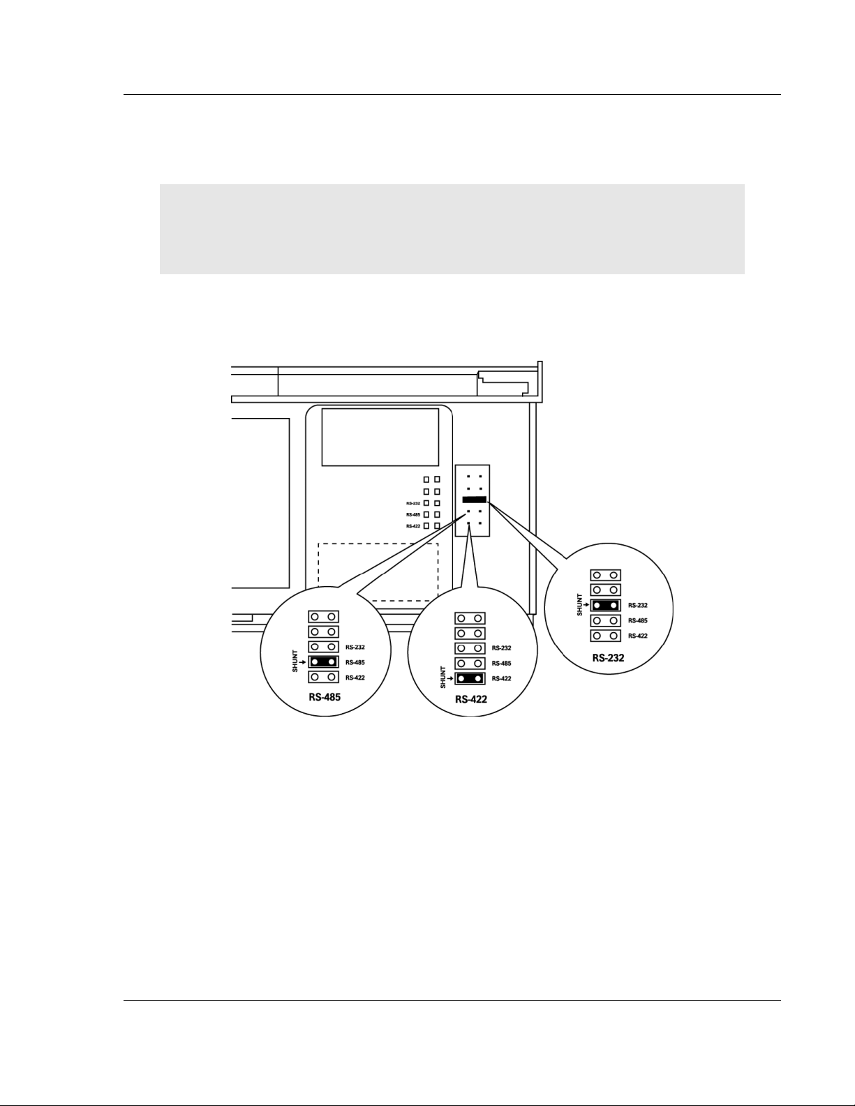
1.3 Setting Port 0 Configuration Jumpers
Before installing the module on the DIN rail, you must set the jumpers for the Port
0 application port.
Note: Ethernet-only ProLinx modules do not use the serial port jumper settings. The serial
configuration jumper settings on an Ethernet-only module have no effect.
Note: The presence of Port 0 depends on the specific combination of protocols in your ProLinx
module. If your module does not have a Port 0, the following jumper settings do not apply.
Port 0 is preconfigured for RS-232. You can move the port configuration jumper
on the back of the module to select RS-485 or RS-422.
The following illustration shows the jumper positions for Port 0:
ProLinx 5000/6000 Series Module
ProSoft Technology, Inc. Page 9 of 61
December 31, 2008
Page 10
PDPS ♦ ProLinx Gateway Start Here
PROFIBUS DP Slave
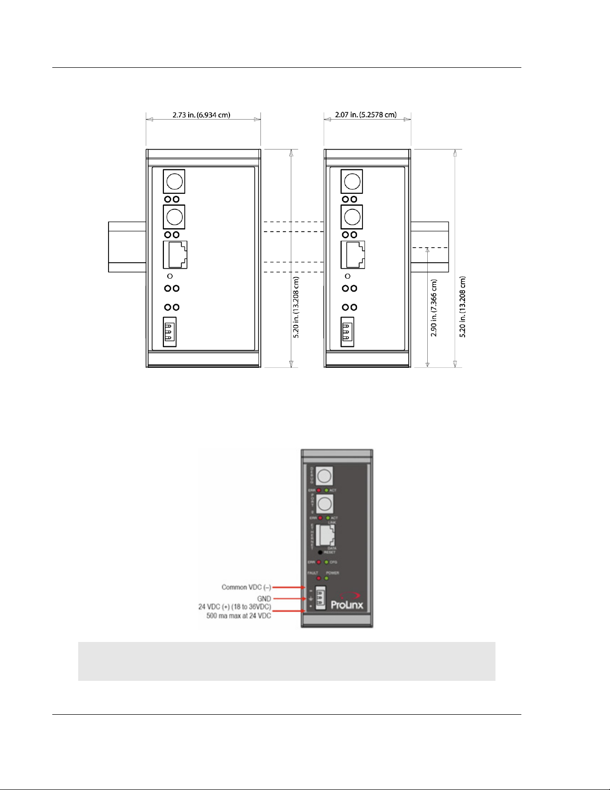
1.4 Mounting the Module on the DIN Rail
ProLinx 5000/6000 Series Module
1.5 Connecting Power to the Unit
WARNING: Ensure that you do not reverse polarity when applying power to the module. This will
cause damage to the module's power supply.
Page 10 of 61 ProSoft Technology, Inc.
December 31, 2008
Page 11
Start Here PDPS ♦ ProLinx Gateway
PROFIBUS DP Slave
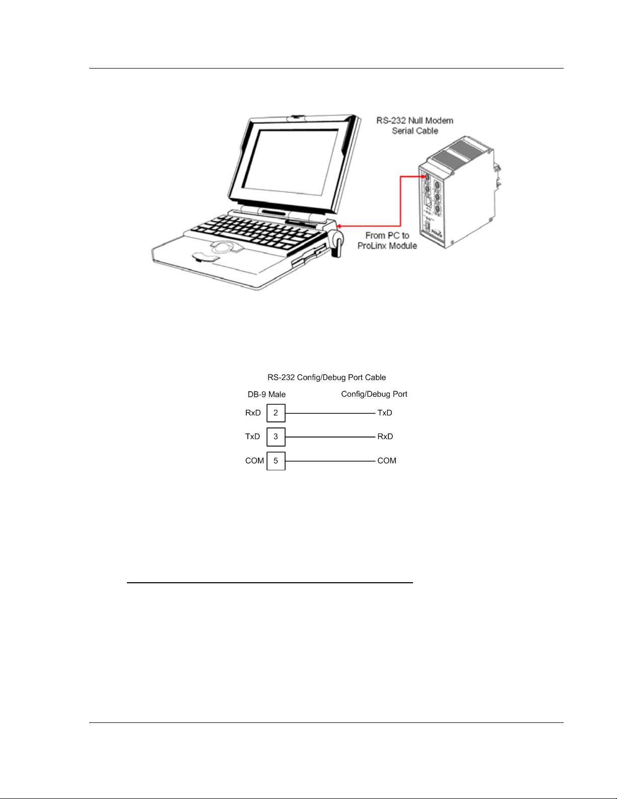
1.6 RS-232 Configuration Port Serial Connection
This port is physically a Mini-DIN connection. A Mini-DIN to DB-9 adapter cable
is included with the module. This port permits ProSoft Configuration Builder to
view configuration and status data in the module and to control the module. The
following illustration shows the pinout for communications on this port.
1.7 Install ProSoft Configuration Builder Software
You must install the ProSoft Configuration Builder (PCB) software in order to
configure the PDPS module. You can always get the newest version of ProSoft
Configuration Builder from the ProSoft Technology web site.
To install ProSoft Configuration Builder from the ProSoft Web Site
1 Open your web browser and navigate to http://www.prosoft-
technology.com/pcb
2 Click the Download Here link to download the latest version of ProSoft
Configuration Builder.
ProSoft Technology, Inc. Page 11 of 61
December 31, 2008
Page 12
PDPS ♦ ProLinx Gateway Start Here
PROFIBUS DP Slave
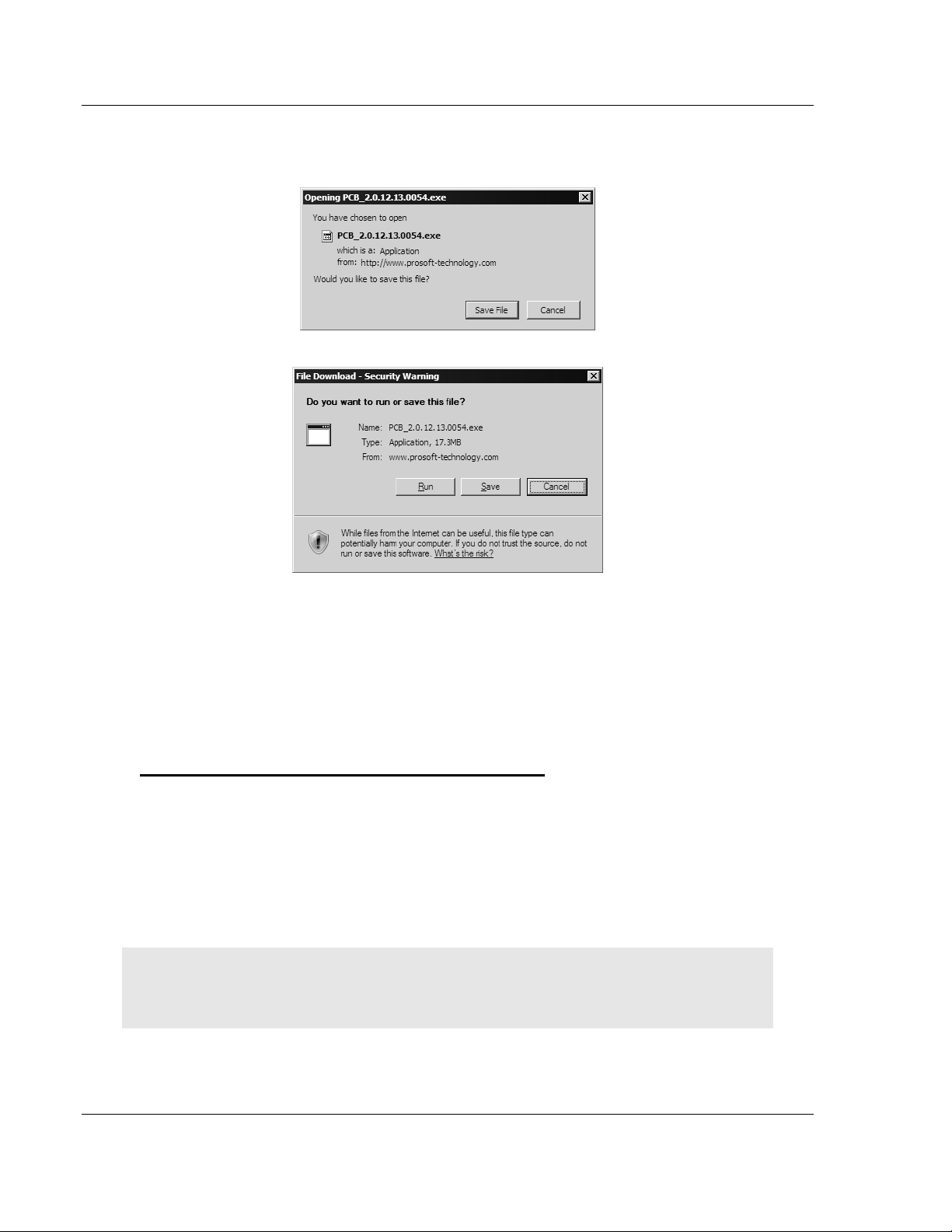
3 Choose "Save" or "Save File" when prompted. The following illustrations
show the file download prompt for two of the most common web browsers.
4 Make a note of the location where you saved the file, for example "Desktop",
or "My Documents", so you can start the installation program.
5 When the download is complete, locate and open the file, and then follow the
instructions on your screen to install the program.
If you do not have access to the Internet, you can install ProSoft Configuration
Builder from the ProSoft Solutions CD-ROM, included in the package with your
PDPS module.
To install ProSoft Configuration Builder from the Product CD
1 Insert the ProSoft Solutions Product CD into the CD drive of your PC. Wait for
the startup screen to appear.
2 On the startup screen, click Product Documentation. This action opens an
explorer window.
3 Click to open the Utilities folder. This folder contains all of the applications
and files you will need to set up and configure your module.
4 Double-click the ProSoft Configuration Builder Setup program and follow the
instructions on your screen to install the software on your PC.
Note: Many of the configuration and maintenance procedures use files and other utilities on the
CD-ROM. You may wish to copy the files from the Utilities folder on the CD-ROM to a convenient
location on your hard drive.
Page 12 of 61 ProSoft Technology, Inc.
December 31, 2008
Page 13

Start Here PDPS ♦ ProLinx Gateway
PROFIBUS DP Slave
1.7.1 Using the help system
Most of the information needed to help you use is provided in a help system that
is always available whenever you are running . The help system does not require
an Internet connection.
To view the help pages, start , open the Help menu, and then choose Contents.
ProSoft Technology, Inc. Page 13 of 61
December 31, 2008
Page 14

PDPS ♦ ProLinx Gateway Start Here
PROFIBUS DP Slave
Page 14 of 61 ProSoft Technology, Inc.
December 31, 2008
Page 15

Functional Overview PDPS ♦ ProLinx Gateway PROFIBUS DP Slave
2 Functional Overview
In This Chapter
About the PROFIBUS Protocol..............................................................15
Port Physical and Protocol Specifications .............................................16
Module Internal Database .....................................................................17
Mailbox Commands...............................................................................18
Mailbox Structure ..................................................................................19
The PROFIBUS slave protocol driver may exist in a single port implementation.
The driver can be configured as a slave interface with other PROFIBUS devices.
The PROFIBUS slave port can be used to continuously interface with other
PROFIBUS devices over a serial communication interface (RS-485).
2.1 About the PROFIBUS Protocol
PROFIBUS (Process Field Bus) is a widely-used, open-standards protocol
created by a consortium of European factory automation suppliers in 1989.
PROFIBUS is a master/slave protocol. The master establishes a connection to
the remote slave. When the connection is established, the master sends the
PROFIBUS commands to the slave. The PDPS module works as a slave only.
The module uses an internal database to pass data and commands between the
processor and the client and server devices on the PROFIBUS network.
PROFIBUS supports a variety of network types. The network type supported by
the PDPS module is PROFIBUS DP (Device Bus), which is designed for remote
I/O systems, motor control centers, and variable speed drives.
ProSoft Technology, Inc. Page 15 of 61
December 31, 2008
Page 16

PDPS ♦ ProLinx Gateway Functional Overview
PROFIBUS DP Slave
2.2 Port Physical and Protocol Specifications
2.2.1 PROFIBUS Slave Port Specifications
Type Specifications
General Parameters
Internal Database Up to 4000 registers (words) available.
GSD File
Downloadable from ProSoft-Technology.com web
site
PROFIBUS Slave
Communication parameters Baud Rate: 9.6 kbps to 12 Mbps
Supported I/O length
Supported PROFIBUS DP features Freeze Mode
Configurable Parameters a) PROFIBUS Node Address: 0 to 125
Status Data
Physical Connection
PROFIBUS Connector
122 words Input data
122 words Output data
200 words max
Sync Mode
Auto Baud Setting
b) Data byte swapping
c) Action on loss of PROFIBUS connection
d) Comm Fail Timeout Multiplier
e) Status Data location in Internal Database
Error codes available on an individual command
basis. In addition, a slave status list is maintained
per active PROFIBUS Slave port.
Standard PROFIBUS DB-9F communication
connector. Cable connection matches PROFIBUS
pin out specification.
Important Note: The slave node address is set to 126 by default in the module configuration file
(page 21). The default node address must be changed to a valid address between 0 to 125 by the
user for the slave to function on the PROFIBUS network.
Page 16 of 61 ProSoft Technology, Inc.
December 31, 2008
Page 17
Functional Overview PDPS ♦ ProLinx Gateway
PROFIBUS DP Slave
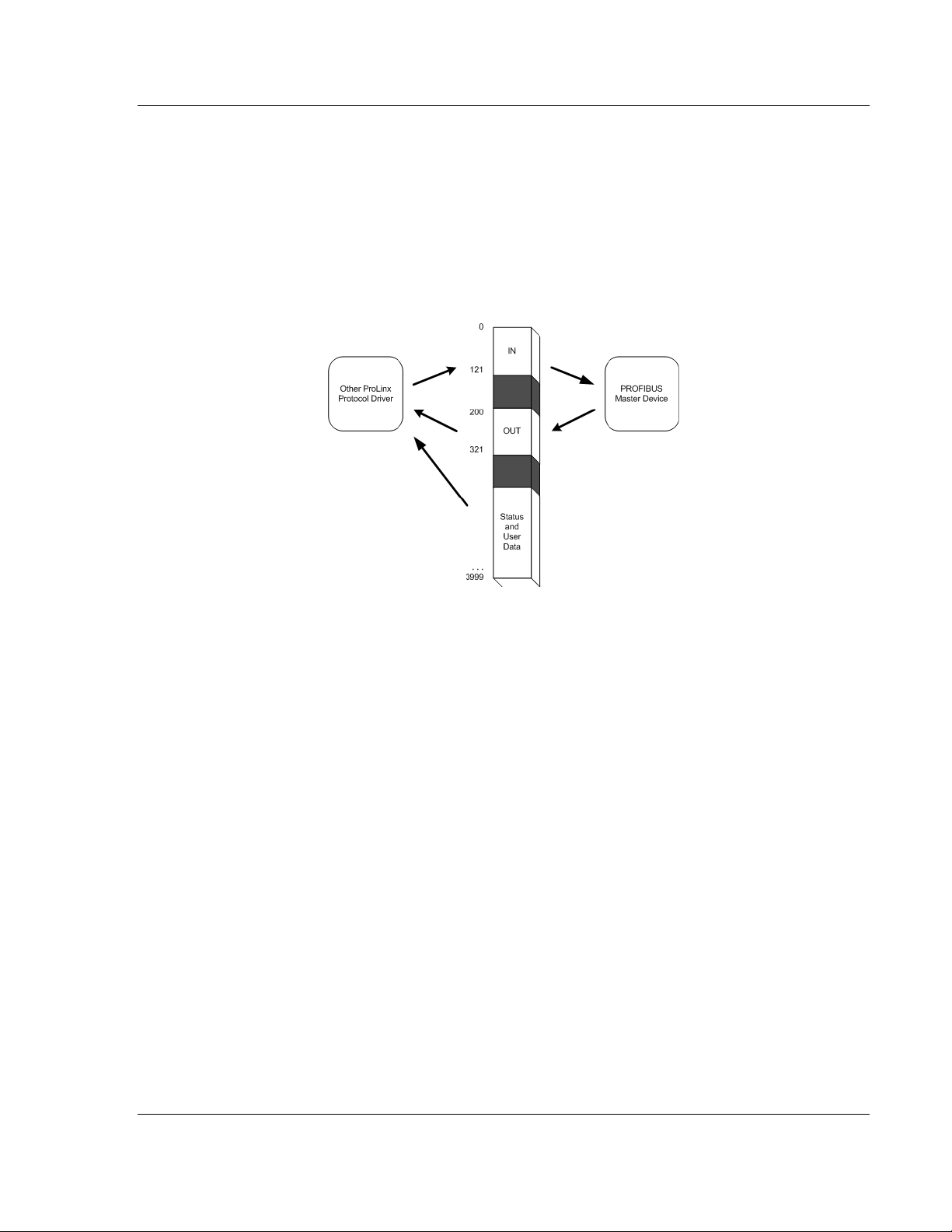
2.3 Module Internal Database
Central to the functionality of the module is the internal database. This database
is shared between all the ports on the module and is used as a conduit to pass
information from one device on one network to one or more devices on another
network. This permits data from devices on one communication port/network to
be viewed and controlled by devices on another port/network. In addition to data
from the slave port, status and error information generated by the module can
also be mapped into the internal database.
2.3.1 PROFIBUS Slave Port Access to Database
The Slave driver uses the database in two ways:
1 A read command issued to a slave device by the slave driver will return the
slave data into the internal database.
2 A write command issued to a slave device by the slave driver uses the data in
the internal database to write to the slave device
Besides the standard PROFIBUS interface reserved Database range from word
0 to word 399, the PDPS driver recognizes a special command code in the
PROFIBUS protocol that causes the PDPS driver to write to, or read from the
Database range word 400 to word 3999. This feature opens up to the user the
whole capacity of the PDPS module's Database.
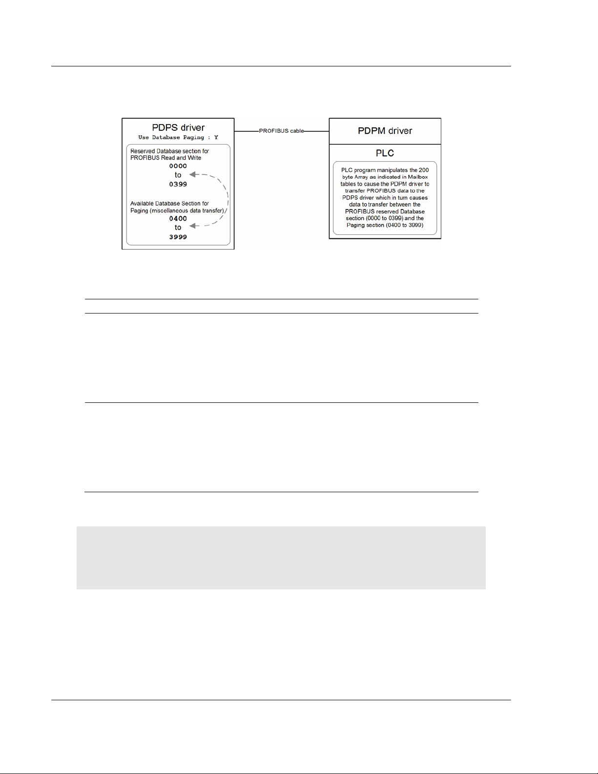
To use the Database Paging functionality in the PDPS driver the following three
items must be implemented.
1 Enable the paging feature in the PDPS module's configuration file under the
[Profibus Slave] section, set Use Database Paging : Y.
2 In PROFIBUS Master module's configuration the PROFIBUS Slave must be
set to 100 Input Words and 100 Output Words.
ProSoft Technology, Inc. Page 17 of 61
December 31, 2008
Page 18
PDPS ♦ ProLinx Gateway Functional Overview
PROFIBUS DP Slave
3 In the PLC Program create an array of 200 bytes. The contents of the array
are described in the Mailbox Command and Mailbox Structure tables.
2.4 Mailbox Commands
Start Value Stop Value Direction Description
150 151
160 161
PLC = PROFIBUS master interface in PLC.
PDPM = PROFIBUS Master.
PDPS = PROFIBUS Slave.
NOTES:
The block number for each device must be changed to trigger an operation.
The I/O data area is owned exclusively by only the PLC or PDPM.
A timeout must be implemented in the PLC in case the PDPM is not present.
PLC to PDPM to
PDPS
PDPS to PDPM to
PLC
Database Write transfer, from the PLC's
perspective.
The value of 150 in the specific Array index
location as indicated in the Mailbox structure
table will cause the PROFIBUS Slave driver to
transfer the data in the 200 Byte array to the
Database locations above word 400. The Value
of 151 stops the data transfer.
Database Read transfer, from the PLC's
perspective.
The value of 160 in the specific Array index
location as indicated in the Mailbox structure
table will cause the PROFIBUS Slave driver to
transfer the data to the 200 Byte array from the
Database locations above word 400. The Value
of 161 stops the data transfer.
Page 18 of 61 ProSoft Technology, Inc.
December 31, 2008
Page 19

Functional Overview PDPS ♦ ProLinx Gateway
PROFIBUS DP Slave
2.5 Mailbox Structure
This 200 Byte Array is located in the PLC containing the PDPM gateway module,
not in the PDPS.
Example Raw Database Exchange. Output from PLC to PDPM
Word
0
1 2 3
2 4 5
3 6 7
4 8 9
5 to 98 10 197
Start
Byte
0 0
1 1
198 198 Reserved. Do not use. 99
199 199
End
Byte
Description
150 (Raw data write).This value tells PDPS driver to write into
Database paging section.
160 (Raw data read). This value tells PDPS driver to read from
Database Paging section.
Start register in database for write. This value tells the PDPS driver
where in the Database Paging section to start writing to.
Number of registers to write (1 to 94). This value tells the PDPS
Driver the quantity of registers to be filled with data.
Start register in database for read. This value tells the PDPS driver
where in the Database Paging section to start reading from.
Number of registers to read (1 to 96). This value tells the PDPS
Driver the quantity of registers to read from.
Words to write to the database. The actual data to be transferred to
the Database paging section. In the PLC, fill these bytes of the
Array with values to be transferred to the PDPS's Database paging
section.
150 (Raw data write). This value tells PDPS driver to write into
Database paging section. Duplicated from Array[0] index.
Example Response Block From PDPM. Input to PLC from PDPM.
Communications acknowledgement.
Word
0
1 2 3
2 4 5
3 to 98 6 197
99 198 199 Reserved. Do not use.
Start
Byte
0 0
1 1
199 199 160 (Raw data read). Signifies the end of the read block
End
Byte
Description
160 (Raw data read). PDPS Driver responded to the PDPM driver
which in turn responded to the PLC that the data in this 200 word
Array is from the PDPS drive's Database paging section.
150 (Raw data write). PDPS driver is responding to the PDPM
driver which in turn responds to the PLC that the data has been
written.
Start register in database for read. PDPS driver is responding to the
PDPM driver which in turn responds to the PLC where in the PDPS
Database paging was the beginning of the data read.
Number of registers to read (1 to 96). This value tells the PLC the
quantity of registers that the PDPS Driver read.
Words read from the database. The actual words that were
readfrom the PDPS Database Paging section.
ProSoft Technology, Inc. Page 19 of 61
December 31, 2008
Page 20

PDPS ♦ ProLinx Gateway Functional Overview
PROFIBUS DP Slave
2.5.1 Mailbox From PLC to Gateway
Start Byte End Byte Description
0 0 Block number of data in block
1 1 Block number of data requested
2 198 Data for block
199 199 Block number of data in block
2.5.2 Mailbox From Gateway to PLC
Start Byte End Byte Description
0 0 Block number of data in block
1 1 Block number last requested by PLC
2 198 Data for block
199 199 Block number of data in block
2.5.3 Example Raw Database Exchange
Start Byte End Byte Description
0 0 150 (Raw data write)
1 1 160 (Raw data read)
2 3 Start register in database for write
4 5 Number of registers to write (1 to 94)
6 7 Start register in database for read
8 9 Number of registers to read (1 to 96)
10 197 Words to write to the database
198 198 Reserved
199 199 150 (Raw data write)
2.5.4 Example Response Block From GW
Start Byte End Byte Description
0 0 160 (Raw data read)
1 1 150 (Raw data write)
2 3 Start register in database for read
4 5 Number of registers to read (1 to 96)
6 197 Words read from the database
198 198 Reserved
199 199 160 (Raw data read)
Page 20 of 61 ProSoft Technology, Inc.
December 31, 2008
Page 21

Configuration PDPS ♦ ProLinx Gateway
PROFIBUS DP Slave
3 Configuration
In This Chapter
Configure the Module............................................................................21
PDPS Protocol Configuration................................................................25
[PROFIBUS SLAVE] .............................................................................26
Set_Param (SAP61)..............................................................................27
Downloading a File from PC to the Module...........................................29
3.1 Configure the Module
3.1.1 Adding a Module
1 Double-click the Default Module icon in the left pane to open the Choose
Module Type dialog box.
Note: ProLinx modules always combine two or more protocols. The following illustration shows an
example ProLinx module with PDPS and one other protocol. Please choose the module type in
ProSoft Configuration Builder that matches the combination of protocols in your ProLinx module.
ProSoft Technology, Inc. Page 21 of 61
December 31, 2008
Page 22

PDPS ♦ ProLinx Gateway Configuration
PROFIBUS DP Slave
On the Choose Module Type dialog box, select the module type.
3.1.2 Module Entries
To configure module parameters
1 Click on the plus sign next to the module icon to expand module information.
Page 22 of 61 ProSoft Technology, Inc.
December 31, 2008
Page 23

Configuration PDPS ♦ ProLinx Gateway
PROFIBUS DP Slave
2 Expand each icon in the list to view the configuration tags. Double-click a tag
to edit the configuration parameters.
3 For parameter entries, select the parameter in the left pane and make your
changes in the right pane.
ProSoft Technology, Inc. Page 23 of 61
December 31, 2008
Page 24

PDPS ♦ ProLinx Gateway Configuration
PROFIBUS DP Slave
For data map entries, click the Add Row button to add an item to the list.
Click Edit Row to edit the parameters.
Click OK to save your changes.
3.1.3 Comment Entries
To add comments to your configuration file:
1 Click the plus sign to the left of the
Comments.
2 Double-click the
appears.
icon. The Edit - Module Comment dialog
icon to expand the Module
3 Enter your comment and click OK to save your changes.
Page 24 of 61 ProSoft Technology, Inc.
December 31, 2008
Page 25

Configuration PDPS ♦ ProLinx Gateway
PROFIBUS DP Slave
3.1.4 Printing a Configuration File
To print a configuration file:
1 Select the Module icon, and then click the right mouse button to open a
shortcut menu.
2 On the shortcut menu, choose View Configuration. This action opens the
View Configuration window.
3 On the View Configuration window, open the File menu, and choose Print.
This action opens the Print dialog box.
4 On the Print dialog box, choose the printer to use from the dropdown list,
select printing options, and then click OK.
3.2 PDPS Protocol Configuration
The following illustration from ProSoft Configuration Builder shows the
PROFIBUS Slave configuration for a ProLinx PDPS module.
ProSoft Technology, Inc. Page 25 of 61
December 31, 2008
Page 26

PDPS ♦ ProLinx Gateway Configuration
PROFIBUS DP Slave
3.3 [PROFIBUS SLAVE]
The PROFIBUS Slave section contains the data that applies to the PROFIBUS
Slave parameters.
3.3.1 Slave Address
0 to 125
The parameter specifies the node address on the PROFIBUS network for the
slave emulated in the module. Each node on the network must have a unique
address.
Note: Although valid PROFIBUS Node addresses range from 0 to 125, Node 0 is not a valid node
number for a Slave module and that Nodes 0, 1, and 2 are usually reserved for PROFIBUS
Masters. Users are advised to use Node numbers 3-125
3.3.2 Swap Input Bytes
Yes or No
This parameter specifies if the data in the input data area of the module is to be
byte swapped. If the order of the bytes in the words stored in the database is not
correct, use this option. A value of Yes causes the module's program to swap the
bytes in each word. A value of No indicates no byte swapping will occur.
3.3.3 Swap Output Bytes
Yes or No
This parameter specifies if the data in the output data area of the module is to be
byte swapped. If the order of the bytes in the words stored in the database is not
correct, use this option. A value of Yes causes the module's program to swap the
bytes in each word. A value of No indicates no byte swapping will occur.
3.3.4 Comm Failure Mode
No xfer on fail
xfer on comm fail
This parameter sets the data transfer mode of the module's PROFIBUS output
image to the internal database when a communication failure on the PROFIBUS
interface is detected. If the parameter is set to "No xfer on fail", the output image
will continue to be transferred. If the parameter is set to "xfer on comm fail", the
output image will not be transferred and the last values will be retained.
Page 26 of 61 ProSoft Technology, Inc.
December 31, 2008
Page 27

Configuration PDPS ♦ ProLinx Gateway
PROFIBUS DP Slave
3.3.5 Comm Timeout Multiplier
1 to 10
This parameter sets the communication timeout value for the module. The value
entered is multiplied by 125 milliseconds to determine the actual timeout value.
For example, a value of 1 specifies a communication timeout of 125 milliseconds.
3.3.6 Use Database Paging
Yes or No
This Parameter Enables or disables user access to the PDPS's Database area
outside the section reserved for the PROFIBUS Protocol in the range of Word
400 to Word 3999.
3.4 Set_Param (SAP61)
ProSoft PROFIBUS Slave (PDPS) devices have a configurable parameter for
SPC3 User Prm Byte. The following illustrations show the value of this parameter
in Sycon, the configuration tool for ProLinx PROFIBUS Master devices, and in
ProSoft Configuration Builder for PROFIBUS, the configuration tool for ProSoft
PROFIBUS Master devices.
ProSoft Technology, Inc. Page 27 of 61
December 31, 2008
Page 28

PDPS ♦ ProLinx Gateway Configuration
PROFIBUS DP Slave
Parameter Data Structure
SPC3 evaluates the first seven data bytes (without user prm data), or the first
eight data bytes (with user prm data). The first seven bytes are specified
according to the standard. The eighth byte is used for SPC3-specific
communications. The additional bytes are available to the application.
Byte Bit Position Designation
0 Lock
1
2
3
4
5
6
7
8 to 243
7 6 5 4 3 2 1 0
Unio
Reg
Req
Sync
Req
Free
Req
WD on Res Res Res Station status
WD_Fact_1
WD_Fact_2
MinTSDR
Ident_Number_High
Ident_Number_Low
Group_Ident
Spec_User_Prm_Byte
User_Prm_Data
Page 28 of 61 ProSoft Technology, Inc.
December 31, 2008
Page 29

Configuration PDPS ♦ ProLinx Gateway
PROFIBUS DP Slave
Byte 7 Spec_User_Prm_Byte
Bit Name Significance Default State
0 Dis_Startbit The start bit monitoring in the receiver
is switched off with this bit
1 Dis_Stopbit Stop bit monitoring in the receiver is
switched off with this bit
2 WD_Base This bit specifies the time base used to
clock the watchdog.
WD_Base = 0: time base 10 ms
WD_Base = 1: time base 1 ms
3 to 4 Res To be parameterized with 0 0
5 Publisher_Enable DXB-publisher-functionality of the
SPC3 is activated with this bit
6 to 7 Res To be parameterized with 0 0
3.5 Downloading a File from PC to the Module
To download a file from the Configuration Builder to the module:
Dis_Startbit = 1,
That is, start bit monitoring is switched off.
Dis_Stopbit = 0
That is, stop bit monitoring is not switched
off.
WD_Base = 0
That is, the time base is 10 ms.
Publisher_Enable = 0, DXB-requesttelegrams are ignored;
Publisher_Enable = 1, DXB-requesttelegramme are processed
1 Verify that your PC is connected to the module with a null-modem serial cable
connected to the serial port on your PC and the serial port on the module
2 Open the Project Menu, and then choose Module.
3 On the Module menu, choose Download. Wait while ProSoft Configuration
scans for communication ports on your PC. When the scan is complete, the
Download dialog box opens.
4 Select the port to use for the download.
5 Click the Download button.
ProSoft Technology, Inc. Page 29 of 61
December 31, 2008
Page 30

PDPS ♦ ProLinx Gateway Configuration
PROFIBUS DP Slave
Page 30 of 61 ProSoft Technology, Inc.
December 31, 2008
Page 31

Diagnostics and Troubleshooting PDPS ♦ ProLinx Gateway PROFIBUS DP Slave
4 Diagnostics and Troubleshooting
In This Chapter
PROFIBUS Slave Error and Status Data...............................................31
Base Module LEDs................................................................................35
PROFIBUS Slave LED Indicators..........................................................35
Definition of Module's Extended Diagnostics Data................................35
There are two ways to troubleshoot ProLinx modules: LEDs located on the front
of the module, and a Debug port that provides a view into the module's internal
database.
4.1 PROFIBUS Slave Error and Status Data
The PROFIBUS Slave Error and Status Data area is discussed in this section.
The data area is initialized with zeros whenever the module is initialized. This
occurs during a cold-start (power-on), reset (reset push-button pressed) or a
warm-boot operation (commanded or loading of new configuration). Counter
values are also initialized to 0 at power up.
Example Internal
Database
Address
10300 0
10301 1 Reserved
10303 3 Reserved
10304 4 Product Codes Bytes 0 and 1
10305 5 Product Codes Bytes 2 and 3
10306 6 Product Codes Bytes 4 and 5
10307 7 Product Codes Bytes 6 and 7
10308 8 Product Codes Bytes 8 and 9
10309 9 PROFIBUS Status Register
10310 10
10311 11
10312 12
10313 to 10399 13 No valid data
Word Offset Description
Diagnostic reporting state
0=normal
1=extended
2=static diagnostics
3=extended/static diagnostics
Module state and last global command received by slave
from a master
Input counter (number of times the input region of the
database is transferred to the input image)
Output counter (number of times the output image is
transferred to the database)
Refer to the following topics to interpret the status/error codes present in the data
area.
ProSoft Technology, Inc. Page 31 of 61
December 31, 2008
Page 32

PDPS ♦ ProLinx Gateway Diagnostics and Troubleshooting
PROFIBUS DP Slave
4.1.1 Diagnostic state - Word 10300
0 = Normal Operation or not in data exchange with Status Register [0] Bit
0x20 set.
1 = Not in data exchange state with the Status Register [0] bit 0x20 not set or
normal operation with the Status Register [0] bit 0x20 not set.
3 = Not in a defined state or in module state 1, 2 or 3.
4 = Normal operation with Status Register [0] bit 0x20 set
4.1.2 PROFIBUS Reserved Words: Word 10301 to Word 10303
Reserved for future use.
4.1.3 Words 10304 to 10308
Example Internal
Database
Address
10304 4 Product Codes Bytes 0 and 1
10305 5 Product Codes Bytes 2 and 3
10306 6 Product Codes Bytes 4 and 5
10307 7 Product Codes Bytes 6 and 7
10308 8 Product Codes Bytes 8 and 9
Word Offset Description
4.1.4 PROFIBUS Status Register: Word 10309
SPC3 ASIC slave status information provided to the master
Bit 0
Bit 1
Bit 2
Bit 3
Offline/Passive-Idle
Offline-/Passive-Idle state
0 = SPC3 is in offline
1 = SPC3 in passive idle
FDL_IND_ST (Fieldbus Data link Layer)
FDL indication is temporarily buffered.
0 = No FDL indication is temporarily buffered.
1 = FDL indication is temporarily buffered.
Diag_Flag
Status diagnostics buffer
0 = The DP master fetches the diagnostics buffer.
1 = The DP master has not yet fetched the diagnostics buffer.
RAM Access Violation
Memory access > 1.5kByte
0 = No address violation
1 = For addresses > 1536 bytes, 1024 is subtracted from the current address,
and there is access to this new address.
Page 32 of 61 ProSoft Technology, Inc.
December 31, 2008
Page 33

Diagnostics and Troubleshooting PDPS ♦ ProLinx Gateway
PROFIBUS DP Slave
Bits 4,5
Bits 6,7
Bits
8 to 11
Bits
12 to 15
DP-State
DP-State Machine state
00 = 'Wait_Prm' state
01 = 'Wait_Cfg' state
10 = 'DATA_EX' state
11 = Not possible
WD-State
Watchdog-State-Machine state
00 = 'Baud_Search' state
01 = 'Baud_Control' state
10 = 'DP_Control' state
11 = Not possible
Baud rate:
The baud rates SPC3 found
0000 = 12 MBaud
0001 = 6 MBaud
0010 = 3 MBaud
0011 = 1.5 MBaud
0100 = 500 kBaud
0101 = 187.5 kBaud
0110 = 93.75 kBaud
0111 = 45.45 kBaud
1000 = 19.2 kBaud
1001 = 9.6 kBaud
Rest = Not possible
SPC3-Release:
Release no. for SPC3
0000 = Release 0
Rest = Not possible
Further explanation of Status Register [0]: Word 10309 Bit states
Bit 0
Offline/Passive-idle
0 = SPC3 exits offline and goes to passive-idle. The idle timer and Wd timer
go offline.
1= SPC3 exits offline and goes to passive-idle. The idle timer and Wd timer
are started.
Bit 4, 5
10 = Data Exchange State is Normal. The SPC3 has a correct configuration.
ProSoft Technology, Inc. Page 33 of 61
December 31, 2008
Page 34

PDPS ♦ ProLinx Gateway Diagnostics and Troubleshooting
PROFIBUS DP Slave
4.1.5 Module State: Word 10310 Byte 0
Indicates the current state of the module.
0 = Normal Operation
1 = Shutdown
2 = File Transfer
3 = SPC3 ASIC problem
4 = Not in data exchange
4.1.6 Last Global Command: Word 10310 Byte 1
The value of the last global command code received from the master.
Bit Designation Significance
0 Reserved
1 Clear_Data
2 Unfreeze With 'Unfreeze': freezing input data is cancelled.
3 Freeze
4 Unsync The 'Unsync' command cancels the 'Sync' comman d.
5 Sync
6,7 Reserved
With this command the ASCI output data is deleted in data transfer
buffer and is changed to next transfer data buffer contents.
The ASCI input data is fetched from next transfer buffer to data
transfer buffer and frozen. New input data is not fetched again until
the master sends the next 'Freeze' command.
The ASCI output data transferred with a WRITE_READ_DATA
telegram is changed from data transfer buffer next state buffer. The
following transferred output data is kept in data transfer buffer until
the next 'Sync' command is given.
The Reserved designation specifies that these bits are reserved for
future function expansions.
4.1.7 PROFIBUS Input Counter: 10311
Input counter is incremented each time the input data is updated.
4.1.8 PROFIBUS Output Counter: Word 10312
Output counter is incremented each time the output data is updated.
4.1.9 Words 10313 to 10399
No valid data
Page 34 of 61 ProSoft Technology, Inc.
December 31, 2008
Page 35

Diagnostics and Troubleshooting PDPS ♦ ProLinx Gateway
PROFIBUS DP Slave
4.2 Base Module LEDs
LED State Description
Power
Err
Off
Green Solid
Off Normal operation. Fault
Red Solid
Off Normal operation. Cfg
Amber Solid
Off Normal operation.
Flashing
Solid Red
Power is not connected to the power terminals. This LED is hardware
driven, so it only requires power to operate.
Power is connected to the power terminals. Verify that the other LEDs
for operational and functional status.
A critical error has occurred. Program executable has failed or has
been user-terminated and is no longer running. Press Reset p/b or
cycle power to clear error. If not, use the Debug procedures described
later in this manual.
The unit is in the configuration mode. The configuration file is being
read and the unit is implementing the configuration values and
initializing the hardware. This will occur during power cycle, or after
pressing the reset button. It also occurs after a cold/warm boot
command is received.
An error condition has been detected and is occurring. Check
configuration.
This condition is indicative of a large number of errors in the application
interface communications. The module's error flag is cleared at the
start of each command (master/client) or receipt of data
(slave/adapter/server).
4.3 PROFIBUS Slave LED Indicators
Active LED Error LED Description
On Off Normal Operation
Off Off Module not receiving power or program terminated
Off On Module configured and waiting for first output data set.
Flashing On PROFIBUS communication problem (not receiving output)
Off Flashing User timeout expired.
On
Rapid Irregular
Configuration problem from master.
flash
Flashing Together Configuration error during initialization.
Flashing Alternately Watchdog timer expired.
4.4 Definition of Module's Extended Diagnostics Data
The Extended Diagnostic Data is reported during startup and initialization
sequence when the master requests diagnostic data from the module. The
Extended Diagnostics is "Device Related" type providing status data (the
extended diagnostic bit 3 in standard diagnostic byte 1 is set = 0). The data
length is normally 14 (0E) bytes displayed in the following format:
Byte(s) Description (HEX)
0 Extended Diagnostics length (normally 14 bytes (0E))
1 to 6 ASCII data for Product Version
7 to 10 ASCII data for Product Name
11 Value of Status Register [0] (see Section 2)
ProSoft Technology, Inc. Page 35 of 61
December 31, 2008
Page 36

PDPS ♦ ProLinx Gateway Diagnostics and Troubleshooting
PROFIBUS DP Slave
Byte(s) Description (HEX)
12 Value of Status Register [1] (see Section 2)
13 Module State (see Section 2)
Bytes 7 through 10 Data - Specific Product Code Value
Each ProLinx application has its own, unique product code. You can determine
the product code from the Version screen in the Configuration/Debug menu.
The following table lists the product codes for some ProLinx modules that
support the PDPS protocol.
Example Product Example Product Code
5105-ASCII-PDPS ASPS
5105-DFCM-PDPS DFPS
5105-DH485-PDPS D4PS
5105-DNPM-PDPS DMPS
5105-DNPS-PDPS D3PS
5105-I101S-PDPS ISPS
5105-I103M-PDPS PSI3
5105-MCM-PDPS PDSM
Sample Diagnostics reported to master.
Translated as follows:
Extended diagnostics length 0E= 14 bytes, Product Version 56 = "V", 30 =
"0", 31 = "1", 2E = ".", 30 = "0", 35 = "5", Product Name 50 = ""P", 44 = ""D", 53
= "S", 34 = "4" (MVI46),
Status Register [0] 41 = SPC3 in passive idle and WD-State is in DP_Control
State, Status Register [1] 03 = 1.5 Baud rate, Module State 04 = not in data
exchange
Page 36 of 61 ProSoft Technology, Inc.
December 31, 2008
Page 37

Diagnostics and Troubleshooting PDPS ♦ ProLinx Gateway
PROFIBUS DP Slave
4.4.1 The Configuration/Debug Menu
The Configuration and Debug menu for this module is arranged as a tree
structure, with the Main Menu at the top of the tree, and one or more sub-menus
for each menu command. The first menu you see when you connect to the
module is the Main menu.
Because this is a text-based menu system, you enter commands by typing the
command letter from your computer keyboard in the diagnostic window in
ProSoft Configuration Builder (PCB). The module does not respond to mouse
movements or clicks. The command executes as soon as you press the
command letter — you do not need to press [Enter]. When you type a command
letter, a new screen will be displayed in your terminal application.
Required Hardware
You can connect directly from your computer's serial port to the serial port on the
module to view configuration information, perform maintenance, and send
(upload) or receive (download) configuration files.
ProSoft Technology recommends the following minimum hardware to connect
your computer to the module:
80486 based processor (Pentium preferred)
1 megabyte of memory
At least one UART hardware-based serial communications port available.
USB-based virtual UART systems (USB to serial port adapters) often do not
function reliably, especially during binary file transfers, such as when
uploading/downloading configuration files or module firmware upgrades.
A null modem serial cable.
Using the Diagnostic Window in ProSoft Configuration Builder
To connect to the module's Configuration/Debug serial port:
1 Start PCB program with the application file to be tested. Right click over the
module icon.
ProSoft Technology, Inc. Page 37 of 61
December 31, 2008
Page 38

PDPS ♦ ProLinx Gateway Diagnostics and Troubleshooting
PROFIBUS DP Slave
2 On the shortcut menu, choose Diagnostics.
3 This action opens the Diagnostics dialog box. Press "?" to display the Main
Menu.
Important: The illustrations of configuration/debug menus in this section are intended as a general
guide, and may not exactly match the configuration/debug menus in your own module.
Page 38 of 61 ProSoft Technology, Inc.
December 31, 2008
Page 39

Diagnostics and Troubleshooting PDPS ♦ ProLinx Gateway
PROFIBUS DP Slave
If there is no response from the module, follow these steps:
1 Verify that the null modem cable is connected properly between your
computer's serial port and the module. A regular serial cable will not work.
2 On computers with more than one serial port, verify that your communication
program is connected to the same port that is connected to the module.
If you are still not able to establish a connection, contact ProSoft Technology for
assistance.
Navigation
All of the sub-menus for this module contain commands to redisplay the menu or
return to the previous menu. You can always return from a sub-menu to the next
higher menu by pressing [M] on your keyboard.
The organization of the menu structure is represented in simplified form in the
following illustration:
The remainder of this section shows you the menus available for this module,
and briefly discusses the commands available to you.
Keystrokes
The keyboard commands on these menus are almost always non-case sensitive.
You can enter most commands in lower case or capital letters.
The menus use a few special characters ([?], [-], [+], [@]) that must be entered
exactly as shown. Some of these characters will require you to use the [Shift],
[Ctrl] or [Alt] keys to enter them correctly. For example, on US English
keyboards, enter the [?] command as [Shift][/].
Also, take care to distinguish capital letter [I] from lower case letter [l] (L) and
number [1]; likewise for capital letter [O] and number [0]. Although these
characters look nearly the same on the screen, they perform different actions on
the module.
ProSoft Technology, Inc. Page 39 of 61
December 31, 2008
Page 40

PDPS ♦ ProLinx Gateway Diagnostics and Troubleshooting
PROFIBUS DP Slave
4.4.2 Main Menu
When you first connect to the module from your computer, your terminal screen
will be blank. To activate the main menu, press the [?] key on your computer's
keyboard. If the module is connected properly, the following menu will appear on
your terminal screen:
Caution: Some of the commands available to you from this menu are designed for advanced
debugging and system testing only, and can cause the module to stop communicating with the
processor or with other devices, resulting in potential data loss or other failures. Only use these
commands if you are specifically directed to do so by ProSoft Technology Technical Support staff.
Some of these command keys are not listed on the menu, but are active nevertheless. Please be
careful when pressing keys so that you do not accidentally execute an unwanted command.
Redisplaying the Menu
Press [?] to display the current menu. Use this command when you are looking
at a screen of data, and want to view the menu choices available to you.
Viewing Block Transfer Statistics
Press [B] from the Main Menu to view the Block Transfer Statistics screen.
Use this command to display the configuration and statistics of the backplane
data transfer operations between the module and the processor. The information
on this screen can help determine if there are communication problems between
the processor and the module.
Tip: To determine the number of blocks transferred each second, mark the numbers displayed at a
specific time. Then some seconds later activate the command again. Subtract the previous
numbers from the current numbers and divide by the quantity of seconds passed between the two
readings.
Viewing Module Configuration
Press [C] to view the Module Configuration screen.
Use this command to display the current configuration and statistics for the
module.
Page 40 of 61 ProSoft Technology, Inc.
December 31, 2008
Page 41

Diagnostics and Troubleshooting PDPS ♦ ProLinx Gateway
PROFIBUS DP Slave
Opening the Session Configuration Menu
Press [P] from the Main Menu Menu to open the PROFIBUS Slave menu. Use
this command to view PROFIBUS Slave configuration information.
The PROFIBUS Slave Menu section has more information about the commands
on this menu.
Receiving the Configuration File
Press [R] to download (receive) the current configuration file from the module.
For more information on receiving and sending configuration files, please see
Uploading and Downloading the Configuration File.
Sending the Configuration File
Press [S] to upload (send) an updated configuration file to the module. For more
information on receiving and sending configuration files, please see Uploading
and Downloading the Configuration File.
Viewing Version Information
Press [V] to view Version information for the module.
Use this command to view the current version of the software for the module, as
well as other important values. You may be asked to provide this information
when calling for technical support on the product.
Values at the bottom of the display are important in determining module
operation. The Program Scan Counter value is incremented each time a
module's program cycle is complete.
Tip: Repeat this command at one-second intervals to determine the frequency of program
execution.
Resetting diagnostic data
Press [U] to reset the status counters for the client and/or servers in the module.
Warm Booting the Module
Caution: Some of the commands available to you from this menu are designed for advanced
debugging and system testing only, and can cause the module to stop communicating with the
processor or with other devices, resulting in potential data loss or other failures. Only use these
commands if you are specifically directed to do so by ProSoft Technology Technical Support staff.
Some of these command keys are not listed on the menu, but are active nevertheless. Please be
careful when pressing keys so that you do not accidentally execute an unwanted command.
Press [W] from the Main Menu to warm boot (restart) the module. This command
will cause the program to exit and reload, refreshing configuration parameters
that must be set on program initialization. Only use this command if you must
force the module to re-boot.
ProSoft Technology, Inc. Page 41 of 61
December 31, 2008
Page 42

PDPS ♦ ProLinx Gateway Diagnostics and Troubleshooting
PROFIBUS DP Slave
Exiting the Program
Caution: Some of the commands available to you from this menu are designed for advanced
debugging and system testing only, and can cause the module to stop communicating with the
processor or with other devices, resulting in potential data loss or other failures. Only use these
commands if you are specifically directed to do so by ProSoft Technology Technical Support staff.
Some of these command keys are not listed on the menu, but are active nevertheless. Please be
careful when pressing keys so that you do not accidentally execute an unwanted command.
Press [Esc] to restart the module and force all drivers to be loaded. The module
will use the configuration stored in the module's Flash ROM to configure the
module.
4.4.3 PROFIBUS Slave Menu
The PROFIBUS Slave menu provides slave (module) status information and
error data.
Press [P] to open the PROFIBUS Slave menu.
Viewing PROFIBUS Slave Configuration
The Configuration Screen displays many specific SPC3 ASIC diagnostic data
useful to ProSoft Technology Technical Support and advanced PROFIBUS
users. Additional information can be found in the SPC3 specification.
Station Address = The configured station address set by the user
DOut Len is the total number of output bytes with the S1, S2 and S3 values
being pointers to the 3 output buffers in the SPC3 chip.
Page 42 of 61 ProSoft Technology, Inc.
December 31, 2008
Page 43

Diagnostics and Troubleshooting PDPS ♦ ProLinx Gateway
PROFIBUS DP Slave
DIn Len is the total number of input bytes with the S1, S2 and S3 values being
pointers to the 3 input buffers in the SPC3 chip.
Diag1Len should always be 6 to represent the minimal number of diagnostic
bytes and S= pointer in SPC3 chip to this data.
Diag2Len is the extended diagnostic buffer length and S is a pointer to this data
in the SPC3 chip.
Aux1 Len: (see SPC3 specification) and S is a pointer to this data in the SPC3
chip.
Aux2 Len: (see SPC3 specification) and S is a pointer to this data in the SPC3
chip.
SSA Len is not used and should be 0 and its pointer S is N/A.
Param Len = is the length of the parameter data for the slave with S as the
pointer in the SPC3 chip to the data.
Cfg Len is the configuration length for the slave with S as the pointer.
RCfg len is that received from the master with S as the pointer.
Ident is the PROFIBUS identification number for the module.
FDL SAP last PTR is the end of all the PDPS data in the SPC3 chip. This value
must be less than 0xFF or there is a memory overflow problem!
Comm Failure mode is that from the configuration file as is the swapping of
input and output data.
Viewing PROFIBUS Status
Enable State
Indicates the initialized state of the PDPS module.
0 = Module is not initialized
1 = Module is initialized
ProSoft Technology, Inc. Page 43 of 61
December 31, 2008
Page 44

PDPS ♦ ProLinx Gateway Diagnostics and Troubleshooting
PROFIBUS DP Slave
Module State
Indicates the current state of the PDPS module.
0 = Normal Operation
1 = Shutdown
2 = File Transfer
3 = SPC3 ASIC problem
4 = Not in data exchange
Status Register [0]
SPC3 ASIC slave status information provided to the master.
Bit 0
Bit 1
Bit 2
Offline/Passive-Idle
Offline-/Passive-Idle state
0 = SPC3 is in offline
1 = SPC3 in passive idle
FDL_IND_ST (Fieldbus Data link Layer)
FDL indication is temporarily buffered.
0 = No FDL indication is temporarily buffered.
1 = FDL indication is temporarily buffered.
Diag_Flag
Status diagnostics buffer
0 = The DP master fetches the diagnostics buffer.
1 = The DP master has not yet fetched the diagnostics buffer.
Bit 3
Bits 4,5
Bits 6,7
RAM Access Violation
Memory access > 1.5kByte
0 = No address violation
1 = For addresses > 1536 bytes, 1024 is subtracted from the current address, and
there is access to this new address.
DP-State
DP-State Machine state
00 = 'Wait_Prm' state
01 = 'Wait_Cfg' state
10 = 'DATA_EX' state
11 = Not possible
WD-State
Watchdog-State-Machine state
00 = 'Baud_Search' state
01 = 'Baud_Control' state
10 = 'DP_Control' state
11 = Not possible
Page 44 of 61 ProSoft Technology, Inc.
December 31, 2008
Page 45

Diagnostics and Troubleshooting PDPS ♦ ProLinx Gateway
PROFIBUS DP Slave
Bit 0
Offline/Passive-idle
0 = SPC3 exits offline and goes to passive-idle. The idle timer and Wd timer
go offline.
1= SPC3 exits offline and goes to passive-idle. The idle timer and Wd timer
are started.
Bit 4, 5
10 = Data Exchange State is Normal. The SPC3 has a correct configuration.
Bits 6, 7
Watchdog Timer
Automatic Baud Rate Identification
The SPC3 is able to identify the baud rate automatically. The "baud search" state
is located after each RESET and also after the watchdog (WD) timer has run out
in the "Baud_Control_state." As a rule, SPC3 begins the search for the set rate
with the highest baud rate. If no SD1 telegram, SD2 telegram, or SD3 telegram
was received completely and without errors during the monitoring time, the
search continues with the next lowest baud rate.
After identifying the correct baud rate, SPC3 switches to the "Baud_Control"
state and monitors the baud rate. The monitoring time can be parameterized
(WD_Baud_Control_Val). The watchdog works with a clock of 100 Hz (10
milliseconds). The watchdog resets each telegram received with no errors to its
own station address. If the timer runs out, SPC3 again switches to the baud
search state.
Further explanation of Status Register [0]: Word 9 Bit states
Bit 0
Offline/Passive-idle
0 = SPC3 exits offline and goes to passive-idle. The idle timer and Wd timer
go offline.
1= SPC3 exits offline and goes to passive-idle. The idle timer and Wd timer
are started.
Bit 4, 5
10 = Data Exchange State is Normal. The SPC3 has a correct configuration.
Bits 6, 7
Watchdog Timer
Automatic Baud Rate Identification
The SPC3 is able to identify the baud rate automatically. The "baud search" state
is located after each RESET and also after the watchdog (WD) timer has run out
in the "Baud_Control_state." As a rule, SPC3 begins the search for the set rate
with the highest baud rate. If no SD1 telegram, SD2 telegram, or SD3 telegram
was received completely and without errors during the monitoring time, the
search continues with the next lowest baud rate.
ProSoft Technology, Inc. Page 45 of 61
December 31, 2008
Page 46

PDPS ♦ ProLinx Gateway Diagnostics and Troubleshooting
PROFIBUS DP Slave
After identifying the correct baud rate, SPC3 switches to the "Baud_Control"
state and monitors the baud rate. The monitoring time can be parameterized
(WD_Baud_Control_Val). The watchdog works with a clock of 100 Hz (10
milliseconds). The watchdog resets each telegram received with no errors to its
own station address. If the timer runs out, SPC3 again switches to the baud
search state.
Baud Rate Monitoring
The located baud rate is constantly monitored in 'Baud_Control.' The watchdog is
reset for each error-free telegram to its own station address. The monitoring time
results from multiplying both 'WD_Baud_Control_Val' (user sets the parameters)
by the time base (10 ms). If the monitoring time runs out, WD_SM again goes to
'Baud_Search'. If the user carries out the DP protocol (DP_Mode = 1, see Mode
register 0) with SPC3, the watchdog is used for the "DP_Control' state, after a
'Set_Param telegram' was received with an enabled response time monitoring
'WD_On = 1.' The watchdog timer remains in the baud rate monitoring state
when there is a switched off 'WD_On = 0' master monitoring. The PROFIBUS DP
state machine is also not reset when the timer runs out. That is, the slave
remains in the DATA_Exchange state, for example.
Response Time Monitoring
The 'DP_Control' state serves response time monitoring of the DP master
(Master_Add). The set monitoring times results from multiplying both watchdog
factors and multiplying the result with the momentarily valid time base (1 ms or
10 ms):
TWD = (1 ms or 10 ms) * WD_Fact_1 * WD_Fact_2 (See byte 7 of the
parameter setting telegram.)
The user can load the two watchdog factors (WD_Fact_1, and WD_Fact_2) and
the time base that represents a measurement for the monitoring time via the
'Set_Param telegram' with any value between 1 and 255.
EXCEPTION: The WD_Fact_1=WD_Fact_2=1 setting is not permissible. The
circuit does not check this setting.
Monitoring times between 2 ms and 650 s - independent of the baud rate - can
be implemented with the permissible watchdog factors. If the monitoring time
runs out, the SPC3 goes again to 'Baud_Control,' and the SPC3 generates the
'WD_DP_Control_Timeout-Interrupt'. In addition, the DP_State machine is reset,
that is, generates the reset states of the buffer management.
If another master accepts SPC3, then there is either a switch to 'Baud_Control"
(WD_On = 0), or there is a delay in 'DP_Control' (WD_On = 1), depending on the
enabled response time monitoring (WD_On = 0).
Page 46 of 61 ProSoft Technology, Inc.
December 31, 2008
Page 47

Diagnostics and Troubleshooting PDPS ♦ ProLinx Gateway
PROFIBUS DP Slave
Status Register [1]
SPC3 ASIC slave status information provided to the master.
Bits
0 to 3
Bits
4 to 7
Baud rate:
The baud rates SPC3 found
0000 = 12 MBaud
0001 = 6 MBaud
0010 = 3 MBaud
0011 = 1.5 MBaud
0100 = 500 kBaud
0101 = 187.5 kBaud
0110 = 93.75 kBaud
0111 = 45.45 kBaud
1000 = 19.2 kBaud
1001 = 9.6 kBaud
Rest = Not possible
SPC3-Release:
Release no. for SPC3
0000 = Release 0
Rest = Not possible
Diagnostic State
0 = Normal Operation or not in data exchange with Status Register [0] Bit
0x20 set.
1 = Not in data exchange state with the Status Register [0] bit 0x20 not set or
normal operation with the Status Register [0] bit 0x20 not set.
3 = Not in a defined state or in module state 1, 2 or 3.
4 = Normal operation with Status Register [0] bit 0x20 set
PROFIBUS Input Counter
Input counter is incremented each time the input data is updated.
PROFIBUS Output Counter
Output counter is incremented each time the output data is updated.
Last Global Command
The value of the last global command code received from the master.
Bit Designation Significance
0 Reserved
1 Clear_Data
2 Unfreeze With 'Unfreeze': freezing input data is cancelled.
3 Freeze
4 Unsync The 'Unsync' command cancels the 'Sync' comman d.
5 Sync
6,7 Reserved
With this command the ASCI output data is deleted in data transfer
buffer and is changed to next transfer data buffer contents.
The ASCI input data is fetched from next transfer buffer to data
transfer buffer and frozen. New input data is not fetched again until
the master sends the next 'Freeze' command.
The ASCI output data transferred with a WRITE_READ_DATA
telegram is changed from data transfer buffer next state buffer. The
following transferred output data is kept in data transfer buffer until
the next 'Sync' command is given.
The Reserved designation specifies that these bits are reserved for
future function expansions.
ProSoft Technology, Inc. Page 47 of 61
December 31, 2008
Page 48

PDPS ♦ ProLinx Gateway Diagnostics and Troubleshooting
PROFIBUS DP Slave
Page 48 of 61 ProSoft Technology, Inc.
December 31, 2008
Page 49

Reference PDPS ♦ ProLinx Gateway
PROFIBUS DP Slave
5 Reference
In This Chapter
GSD File - prlx05a5.gsd........................................................................49
5.1 GSD File - prlx05a5.gsd
;============================================================
; Profibus Device Database of:
; ProLinx Communication Gateways, Inc.
; Model: ProLinx Profibus Slave
; Description: Profibus DP Slave
; Language: English
; Date: 01.16.2006
; Author: ProLinx Communication Gateways, Inc.
; Rev Date Description
; A 01/16/06 Max_Output_Len and Max_Input_Len increased to 244
;============================================================
#Profibus_DP
GSD_Revision = 2
;These are text strings associated with each parameter
;This application only uses one parameter byte required
;by the SPC3 ASIC.
ExtUserPrmData=0 "SPC3 User Prm Byte" ;
Unsigned8 0 0-7
EndExtUserPrmData
; Device identification
Vendor_Name="ProLinx Comm Gateways Inc."
Model_Name = "ProLinx Profibus Slave"
Revision = "Version 1.00"
Ident_Number = 0x05A5
Protocol_Ident = 0 ; DP protocol
Station_Type = 0 ; Slave device
FMS_supp = 0 ; FMS not supported
Hardware_Release = "Rev. 1.00"
Software_Release = "Rev. 1.00"
; Supported baudrates
9.6_supp = 1
19.2_supp = 1
45.45_supp = 1
93.75_supp = 1
187.5_supp = 1
500_supp = 1
1.5M_supp = 1
ProSoft Technology, Inc. Page 49 of 61
December 31, 2008
Page 50

PDPS ♦ ProLinx Gateway Reference
PROFIBUS DP Slave
3M_supp=1
6M_supp=1
12M_supp=1
; Maximum responder time for supported baudrates
MaxTsdr_9.6 = 60
MaxTsdr_19.2 = 60
MaxTsdr_45.45 = 250
MaxTsdr_93.75 = 60
MaxTsdr_187.5 = 60
MaxTsdr_500 = 100
MaxTsdr_1.5M = 150
MaxTsdr_3M = 250
MaxTsdr_6M = 450
MaxTsdr_12M = 800
; Supported hardware features
Redundancy = 0 ; not supported
Repeater_Ctrl_Sig = 2 ; TTL
24V_Pins = 0 ; not connected
Implementation_Type = "SPC3"
; Supported DP features
Freeze_Mode_supp = 1 ; supported
Sync_Mode_supp = 1 ; supported
Auto_Baud_supp = 1 ; supported
Set_Slave_Add_supp = 0 ; not supported
;
;--Slave specific data----Bitmap_Device = "ProLnx_R"
Bitmap_Diag = "ProLnx_D"
Bitmap_SF = "ProLnx_S"
; Default Length of User Parameter
User_Prm_Data_Len = 1
; Default User Parameter string:
User_Prm_Data = 0x00
Ext_User_Prm_Data_Const(0)= 0x00
Ext_User_Prm_Data_Ref(0)=0
; Maximum polling frequency
Min_Slave_Intervall = 1 ;100 µs
; Maximum supported sizes
Modular_Station = 1 ; modular
Max_Module = 14 ; logical modules emulated on the card
Max_Input_Len = 244
Max_Output_Len = 244
Max_Data_Len = 400
Modul_Offset=0
Slave_Family=9
Max_Diag_Data_Len = 20
;Refer to the ProSoft Profibus Slave documentation for a complete discussion of
Page 50 of 61 ProSoft Technology, Inc.
December 31, 2008
Page 51

Reference PDPS ♦ ProLinx Gateway
PROFIBUS DP Slave
;the extended diagnostic data.
;
; Module byte-organised send data
;
Module = "Empty Slot" 0x00
EndModule
;
; Module word size send data
;
Module = "1 Word Input" 0x50
EndModule
Module = "2 Words Input" 0x51
EndModule
Module = "3 Words Input" 0x52
EndModule
Module = "4 Words Input" 0x53
EndModule
Module = "5 Words Input" 0x54
EndModule
Module = "6 Words Input" 0x55
EndModule
Module = "7 Words Input" 0x56
EndModule
Module = "8 Words Input" 0x57
EndModule
Module = "9 Words Input" 0x58
EndModule
Module = "10 Words Input" 0x59
EndModule
Module = "11 Words Input" 0x5A
EndModule
Module = "12 Words Input" 0x5B
EndModule
Module = "13 Words Input" 0x5C
EndModule
Module = "14 Words Input" 0x5D
EndModule
Module = "15 Words Input" 0x5E
EndModule
Module = "16 Words Input" 0x5F
EndModule
;
; Module word size receive data
;
Module = "1 Word Output" 0x60
EndModule
Module = "2 Words Output" 0x61
EndModule
Module = "3 Words Output" 0x62
EndModule
Module = "4 Words Output" 0x63
EndModule
Module = "5 Words Output" 0x64
EndModule
Module = "6 Words Output" 0x65
ProSoft Technology, Inc. Page 51 of 61
December 31, 2008
Page 52

PDPS ♦ ProLinx Gateway Reference
PROFIBUS DP Slave
EndModule
Module = "7 Words Output" 0x66
EndModule
Module = "8 Words Output" 0x67
EndModule
Module = "9 Words Output" 0x68
EndModule
Module = "10 Words Output" 0x69
EndModule
Module = "11 Words Output" 0x6A
EndModule
Module = "12 Words Output" 0x6B
EndModule
Module = "13 Words Output" 0x6C
EndModule
Module = "14 Words Output" 0x6D
EndModule
Module = "15 Words Output" 0x6E
EndModule
Module = "16 Words Output" 0x6F
EndModule
Page 52 of 61 ProSoft Technology, Inc.
December 31, 2008
Page 53

Support, Service & Warranty PDPS ♦ ProLinx Gateway
PROFIBUS DP Slave
6 Support, Service & Warranty
In This Chapter
How to Contact Us: Technical Support..................................................53
Return Material Authorization (RMA) Policies and Conditions...............54
LIMITED WARRANTY...........................................................................55
ProSoft Technology, Inc. (ProSoft) is committed to providing the most efficient
and effective support possible. Before calling, please gather the following
information to assist in expediting this process:
1 Product Version Number
2 System architecture
3 Network details
If the issue is hardware related, we will also need information regarding:
1 Module configuration and contents of file
o Module Operation
o Configuration/Debug status information
o LED patterns
2 Information about the processor and user data files as viewed through and
LED patterns on the processor.
3 Details about the serial devices interfaced, if any.
6.1 How to Contact Us: Technical Support
Internet
Asia Pacific
+603.7724.2080, support.asia@prosoft-technology.com
Languages spoken include: Chinese, English
Europe (location in Toulouse, France)
+33 (0) 5.34.36.87.20, support.EMEA@prosoft-technology.com
Languages spoken include: French, English
North America/Latin America (excluding Brasil) (location in California)
+1.661.716.5100, support@prosoft-technology.com
Languages spoken include: English, Spanish
For technical support calls within the United States, an after-hours answering system allows pager
access to one of our qualified technical and/or application support engineers at any time t o answer
your questions.
Brasil (location in Sao Paulo)
+55-11-5084-5178 , eduardo@prosoft-technology.com
Languages spoken include: Portuguese, English
Web Site: http://www.prosoft-technology.com/support
E-mail address: support@prosoft-technology.com
ProSoft Technology, Inc. Page 53 of 61
December 31, 2008
Page 54

PDPS ♦ ProLinx Gateway Support, Service & Warranty
PROFIBUS DP Slave
6.2 Return Material Authorization (RMA) Policies and Conditions
The following RMA Policies and Conditions (collectively, "RMA Policies") apply to
any returned Product. These RMA Policies are subject to change by ProSoft
without notice. For warranty information, see "Limited Warranty". In the event of
any inconsistency between the RMA Policies and the Warranty, the Warranty
shall govern.
6.2.1 All Product Returns:
a) In order to return a Product for repair, exchange or otherwise, the
Customer must obtain a Returned Material Authorization (RMA) number
from ProSoft and comply with ProSoft shipping instructions.
b) In the event that the Customer experiences a problem with the Product for
any reason, Customer should contact ProSoft Technical Support at one of
the telephone numbers listed above (page 53). A Technical Support
Engineer will request that you perform several tests in an attempt to
isolate the problem. If after completing these tests, the Product is found to
be the source of the problem, we will issue an RMA.
c) All returned Products must be shipped freight prepaid, in the original
shipping container or equivalent, to the location specified by ProSoft, and
be accompanied by proof of purchase and receipt date. The RMA number
is to be prominently marked on the outside of the shipping box. Customer
agrees to insure the Product or assume the risk of loss or damage in
transit. Products shipped to ProSoft using a shipment method other than
that specified by ProSoft or shipped without an RMA number will be
returned to the Customer, freight collect. Contact ProSoft Technical
Support for further information.
d) A 10% restocking fee applies to all warranty credit returns whereby a
Customer has an application change, ordered too many, does not need,
etc.
6.2.2 Procedures for Return of Units Under Warranty:
A Technical Support Engineer must approve the return of Product under
ProSoft's Warranty:
a) A replacement module will be shipped and invoiced. A purchase order will
be required.
b) Credit for a product under warranty will be issued upon receipt of
authorized product by ProSoft at designated location referenced on the
Return Material Authorization.
6.2.3 Procedures for Return of Units Out of Warranty:
a) Customer sends unit in for evaluation
b) If no defect is found, Customer will be charged the equivalent of $100
USD, plus freight charges, duties and taxes as applicable. A new
purchase order will be required.
Page 54 of 61 ProSoft Technology, Inc.
December 31, 2008
Page 55

Support, Service & Warranty PDPS ♦ ProLinx Gateway
PROFIBUS DP Slave
c) If unit is repaired, charge to Customer will be 30% of current list price
(USD) plus freight charges, duties and taxes as applicable. A new
purchase order will be required or authorization to use the purchase order
submitted for evaluation fee.
The following is a list of non-repairable units:
o 3150 - All
o 3750
o 3600 - All
o 3700
o 3170 - All
o 3250
o 1560 - Can be repaired, only if defect is the power supply
o 1550 - Can be repaired, only if defect is the power supply
o 3350
o 3300
o 1500 - All
6.2.4 Purchasing Warranty Extension:
a) ProSoft's standard warranty period is three (3) years from the date of
shipment as detailed in "Limited Warranty (page 55)". The Warranty
Period may be extended at the time of equipment purchase for an
additional charge, as follows:
• Additional 1 year = 10% of list price
• Additional 2 years = 20% of list price
• Additional 3 years = 30% of list price
6.3 LIMITED WARRANTY
This Limited Warranty ("Warranty") governs all sales of hardware, software and
other products (collectively, "Product") manufactured and/or offered for sale by
ProSoft, and all related services provided by ProSoft, including maintenance,
repair, warranty exchange, and service programs (collectively, "Services"). By
purchasing or using the Product or Services, the individual or entity purchasing or
using the Product or Services ("Customer") agrees to all of the terms and
provisions (collectively, the "Terms") of this Limited Warranty. All sales of
software or other intellectual property are, in addition, subject to any license
agreement accompanying such software or other intellectual property.
ProSoft Technology, Inc. Page 55 of 61
December 31, 2008
Page 56

PDPS ♦ ProLinx Gateway Support, Service & Warranty
PROFIBUS DP Slave
6.3.1 What Is Covered By This Warranty
a) Warranty On New Products: ProSoft warrants, to the original purchaser,
that the Product that is the subject of the sale will (1) conform to and
perform in accordance with published specifications prepared, approved
and issued by ProSoft, and (2) will be free from defects in material or
workmanship; provided these warranties only cover Product that is sold as
new. This Warranty expires three years from the date of shipment (the
"Warranty Period"). If the Customer discovers within the Warranty Period
a failure of the Product to conform to specifications, or a defect in material
or workmanship of the Product, the Customer must promptly notify
ProSoft by fax, email or telephone. In no event may that notification be
received by ProSoft later than 39 months. Within a reasonable time after
notification, ProSoft will correct any failure of the Product to conform to
specifications or any defect in material or workmanship of the Product,
with either new or used replacement parts. Such repair, including both
parts and labor, will be performed at ProSoft's expense. All warranty
service will be performed at service centers designated by ProSoft.
b) Warranty On Services: Materials and labor performed by ProSoft to repair
a verified malfunction or defect are warranteed in the terms specified
above for new Product, provided said warranty will be for the period
remaining on the original new equipment warranty or, if the original
warranty is no longer in effect, for a period of 90 days from the date of
repair.
6.3.2 What Is Not Covered By This Warranty
a) ProSoft makes no representation or warranty, expressed or implied, that
the operation of software purchased from ProSoft will be uninterrupted or
error free or that the functions contained in the software will meet or
satisfy the purchaser's intended use or requirements; the Customer
assumes complete responsibility for decisions made or actions taken
based on information obtained using ProSoft software.
b) This Warranty does not cover the failure of the Product to perform
specified functions, or any other non-conformance, defects, losses or
damages caused by or attributable to any of the following: (i) shipping; (ii)
improper installation or other failure of Customer to adhere to ProSoft's
specifications or instructions; (iii) unauthorized repair or maintenance; (iv)
attachments, equipment, options, parts, software, or user-created
programming (including, but not limited to, programs developed with any
IEC 61131-3, "C" or any variant of "C" programming languages) not
furnished by ProSoft; (v) use of the Product for purposes other than those
for which it was designed; (vi) any other abuse, misapplication, neglect or
misuse by the Customer; (vii) accident, improper testing or causes
external to the Product such as, but not limited to, exposure to extremes
of temperature or humidity, power failure or power surges; or (viii)
disasters such as fire, flood, earthquake, wind and lightning.
Page 56 of 61 ProSoft Technology, Inc.
December 31, 2008
Page 57

Support, Service & Warranty PDPS ♦ ProLinx Gateway
PROFIBUS DP Slave
c) The information in this Agreement is subject to change without notice.
ProSoft shall not be liable for technical or editorial errors or omissions
made herein; nor for incidental or consequential damages resulting from
the furnishing, performance or use of this material. The user guide
included with your original product purchase from ProSoft contains
information protected by copyright. No part of the guide may be duplicated
or reproduced in any form without prior written consent from ProSoft.
6.3.3 Disclaimer Regarding High Risk Activities
Product manufactured or supplied by ProSoft is not fault tolerant and is not
designed, manufactured or intended for use in hazardous environments requiring
fail-safe performance including and without limitation: the operation of nuclear
facilities, aircraft navigation of communication systems, air traffic control, direct
life support machines or weapons systems in which the failure of the product
could lead directly or indirectly to death, personal injury or severe physical or
environmental damage (collectively, "high risk activities"). ProSoft specifically
disclaims any express or implied warranty of fitness for high risk activities.
6.3.4 Intellectual Property Indemnity
Buyer shall indemnify and hold harmless ProSoft and its employees from and
against all liabilities, losses, claims, costs and expenses (including attorney's
fees and expenses) related to any claim, investigation, litigation or proceeding
(whether or not ProSoft is a party) which arises or is alleged to arise from Buyer's
acts or omissions under these Terms or in any way with respect to the Products.
Without limiting the foregoing, Buyer (at its own expense) shall indemnify and
hold harmless ProSoft and defend or settle any action brought against such
Companies to the extent based on a claim that any Product made to Buyer
specifications infringed intellectual property rights of another party. ProSoft
makes no warranty that the product is or will be delivered free of any person's
claiming of patent, trademark, or similar infringement. The Buyer assumes all
risks (including the risk of suit) that the product or any use of the product will
infringe existing or subsequently issued patents, trademarks, or copyrights.
a) Any documentation included with Product purchased from ProSoft is
protected by copyright and may not be duplicated or reproduced in any
form without prior written consent from ProSoft.
b) ProSoft's technical specifications and documentation that are included
with the Product are subject to editing and modification without notice.
c) Transfer of title shall not operate to convey to Customer any right to make,
or have made, any Product supplied by ProSoft.
d) Customer is granted no right or license to use any software or other
intellectual property in any manner or for any purpose not expressly
permitted by any license agreement accompanying such software or other
intellectual property.
ProSoft Technology, Inc. Page 57 of 61
December 31, 2008
Page 58

PDPS ♦ ProLinx Gateway Support, Service & Warranty
PROFIBUS DP Slave
e) Customer agrees that it shall not, and shall not authorize others to, copy
software provided by ProSoft (except as expressly permitted in any
license agreement accompanying such software); transfer software to a
third party separately from the Product; modify, alter, translate, decode,
decompile, disassemble, reverse-engineer or otherwise attempt to derive
the source code of the software or create derivative works based on the
software; export the software or underlying technology in contravention of
applicable US and international export laws and regulations; or use the
software other than as authorized in connection with use of Product.
f) Additional Restrictions Relating To Software And Other Intellectual
Property
In addition to compliance with the Terms of this Warranty, Customers
purchasing software or other intellectual property shall comply with any
license agreement accompanying such software or other intellectual
property. Failure to do so may void this Warranty with respect to such
software and/or other intellectual property.
6.3.5 Disclaimer of all Other Warranties
The Warranty set forth in What Is Covered By This Warranty (page 56) are in lieu
of all other warranties, express or implied, including but not limited to the implied
warranties of merchantability and fitness for a particular purpose.
6.3.6 Limitation of Remedies **
In no event will ProSoft or its Dealer be liable for any special, incidental or
consequential damages based on breach of warranty, breach of contract,
negligence, strict tort or any other legal theory. Damages that ProSoft or its
Dealer will not be responsible for included, but are not limited to: Loss of profits;
loss of savings or revenue; loss of use of the product or any associated
equipment; loss of data; cost of capital; cost of any substitute equipment,
facilities, or services; downtime; the claims of third parties including, customers of
the Purchaser; and, injury to property.
** Some areas do not allow time limitations on an implied warranty, or allow the exclusion or
limitation of incidental or consequential damages. In such areas, the above limitations may not
apply. This Warranty gives you specific legal rights, and you may also have other rights which vary
from place to place.
6.3.7 Time Limit for Bringing Suit
Any action for breach of warranty must be commenced within 39 months
following shipment of the Product.
Page 58 of 61 ProSoft Technology, Inc.
December 31, 2008
Page 59

Support, Service & Warranty PDPS ♦ ProLinx Gateway
PROFIBUS DP Slave
6.3.8 No Other Warranties
Unless modified in writing and signed by both parties, this Warranty is
understood to be the complete and exclusive agreement between the parties,
suspending all oral or written prior agreements and all other communications
between the parties relating to the subject matter of this Warranty, including
statements made by salesperson. No employee of ProSoft or any other party is
authorized to make any warranty in addition to those made in this Warranty. The
Customer is warned, therefore, to check this Warranty carefully to see that it
correctly reflects those terms that are important to the Customer.
6.3.9 Allocation of Risks
This Warranty allocates the risk of product failure between ProSoft and the
Customer. This allocation is recognized by both parties and is reflected in the
price of the goods. The Customer acknowledges that it has read this Warranty,
understands it, and is bound by its Terms.
6.3.10 Controlling Law and Severability
This Warranty shall be governed by and construed in accordance with the laws of
the United States and the domestic laws of the State of California, without
reference to its conflicts of law provisions. If for any reason a court of competent
jurisdiction finds any provisions of this Warranty, or a portion thereof, to be
unenforceable, that provision shall be enforced to the maximum extent
permissible and the remainder of this Warranty shall remain in full force and
effect. Any cause of action with respect to the Product or Services must be
instituted in a court of competent jurisdiction in the State of California.
ProSoft Technology, Inc. Page 59 of 61
December 31, 2008
Page 60

Index PDPS ♦ ProLinx Gateway
PROFIBUS DP Slave
I
Important Installation Instructions • 2
Index
Install ProSoft Configuration Builder Software • 11
Intellectual Property Indemnity • 57
K
[
[PROFIBUS SLAVE] • 26
A
About the PROFIBUS Protocol • 15
Adding a Module • 21
All Product Returns: • 54
All ProLinx® Products • 2
Allocation of Risks • 59
B
Base Module LEDs • 35
Baud Rate Monitoring • 46
C
Comm Failure Mode • 26
Comm Timeout Multiplier • 27
Comment Entries • 24
Configuration • 16, 21
Configure the Module • 21
Connecting Power to the Unit • 10
Controlling Law and Severability • 59
D
Definition of Module's Extended Diagnostics Data • 35
Diagnostic State • 47
Diagnostic state - Word 10300 • 32
Diagnostics and Troubleshooting • 31
Disclaimer of all Other Warranties • 58
Disclaimer Regarding High Risk Activities • 57
Downloading a File from PC to the Module • 29
E
Example Raw Database Exchange • 20
Example Response Block From GW • 20
Exiting the Program • 42
F
Functional Overview • 15
Further explanation of Status Register [0]
Word 9 Bit states • 45
G
GSD File - prlx05a5.gsd • 49
H
How to Contact Us
Technical Support • 53, 54
Keystrokes • 39
L
Last Global Command • 47
Word 10310 Byte 1 • 34
Limitation of Remedies ** • 58
LIMITED WARRANTY • 55
M
Mailbox Commands • 18
Mailbox From Gateway to PLC • 20
Mailbox From PLC to Gateway • 20
Mailbox Structure • 19
Main Menu • 40
Module Entries • 22
Module Internal Database • 17
Module State
Word 10310 Byte 0 • 34
Mounting the Module on the DIN Rail • 10
N
Navigation • 39
No Other Warranties • 59
O
Opening the Session Configuration Menu • 41
P
Package Contents • 8
PDPS Protocol Configuration • 25
Pinouts • 2
Port Physical and Protocol Specifications • 16
Printing a Configuration File • 25
Procedures for Return of Units Out of Warranty: • 54
Procedures for Return of Units Under Warranty: • 54
PROFIBUS Input Counter • 47
10311 • 34
PROFIBUS Output Counter • 47
Word 10312 • 34
PROFIBUS Reserved Words
Word 10301 to Word 10303 • 32
PROFIBUS Slave Error and Status Data • 31
PROFIBUS Slave LED Indicators • 35
PROFIBUS Slave Menu • 42
PROFIBUS Slave Port Access to Database • 17
PROFIBUS Slave Port Specifications • 16
PROFIBUS Status Register
Word 10309 • 32
ProLinx Modules with Ethernet Ports • 2
ProSoft® Product Documentation • 3
Purchasing Warranty Extension: • 55
ProSoft Technology, Inc. Page 60 of 61
December 31, 2008
Page 61

Index PDPS ♦ ProLinx Gateway
PROFIBUS DP Slave
R
Receiving the Configuration File • 41
Redisplaying the Menu • 40
Reference • 49
Required Hardware • 37
Resetting diagnostic data • 41
Response Time Monitoring • 46
Return Material Authorization (RMA) Policies and
Conditions • 54
RS-232 Configuration Port Serial Connection • 11
S
Sending the Configuration File • 41
Set_Param (SAP61) • 27
Setting Port 0 Configuration Jumpers • 9
Slave Address • 26
Start Here • 7
Status Register [0] • 44
Status Register [1] • 47
Support, Service & Warranty • 53
Swap Input Bytes • 26
Swap Output Bytes • 26
System Requirements • 7
T
The Configuration/Debug Menu • 37
Time Limit for Bringing Suit • 58
To Order a Series C mode with the -WEB option: • 2
To upgrade a previously purchased Series C model: •
2
U
Use Database Paging • 27
Using the Diagnostic Window in ProSoft Configuration
Builder • 37
Using the help system • 13
V
Viewing Block Transfer Statistics • 40
Viewing Module Configuration • 40
Viewing PROFIBUS Slave Configuration • 42
Viewing PROFIBUS Status • 43
Viewing Version Information • 41
W
Warm Booting the Module • 41
What Is Covered By This Warranty • 56, 58
What Is Not Covered By This Warranty • 56
Words 10304 to 10308 • 32
Words 10313 to 10399 • 34
Y
Your Feedback Please • 3
ProSoft Technology, Inc. Page 61 of 61
December 31, 2008
 Loading...