

Page 1
5204SE-MNETPDPMV1
ProLinx Gateway
Modbus TCP/IP to PROFIBUS DP-V1
Pass-Through Master
12/21/2009
USER MANUAL
Page 2
Important Installation Instructions
Power, Input, and Output (I/O) wiring must be in accordance with Class I, Division 2 wiring methods, Article 501-4 (b)
of the National Electrical Code, NFPA 70 for installation in the U.S., or as specified in Section 18-1J2 of the Canadian
Electrical Code for installations in Canada, and in accordance with the authority having jurisdiction. The following
warnings must be heeded:
A WARNING - EXPLOSION HAZARD - SUBSTITUTION OF COMPONENTS MAY IMPAIR SUITABILITY FOR
CLASS I, DIV. 2;
B WARNING - EXPLOSION HAZARD - WHEN IN HAZARDOUS LOCATIONS, TURN OFF POWER BEFORE
REPLACING OR WIRING MODULES
C WARNING - EXPLOSION HAZARD - DO NOT DISCONNECT EQUIPMENT UNLESS POWER HAS BEEN
SWITCHED OFF OR THE AREA IS KNOWN TO BE NONHAZARDOUS.
D THIS DEVICE SHALL BE POWERED BY CLASS 2 OUTPUTS ONLY.
All ProLinx® Products
WARNING – EXPLOSION HAZARD – DO NOT DISCONNECT EQUIPMENT UNLESS POWER HAS BEEN
SWITCHED OFF OR THE AREA IS KNOWN TO BE NON-HAZARDOUS.
AVERTISSEMENT – RISQUE D'EXPLOSION – AVANT DE DÉCONNECTER L'EQUIPMENT, COUPER LE
COURANT OU S'ASSURER QUE L'EMPLACEMENT EST DÉSIGNÉ NON DANGEREUX.
Markings
UL/cUL ISA 12.12.01 Class I, Div 2 Groups A, B, C, D
cUL C22.2 No. 213-M1987
243333 183151
CL I Div 2 GPs A, B, C, D
Temp Code T5
II 3 G
Ex nA nL IIC T5 X
0° C <= Ta <= 60° C
II – Equipment intended for above ground use (not for use in mines).
3 – Category 3 equipment, investigated for normal operation only.
G – Equipment protected against explosi ve gasses .
Your Feedback Please
We always want you to feel that you made the right decision to use our products. If you have suggestions, comments,
compliments or complaints about the product, documentation, or support, please write or call us.
ProSoft Technology
5201 Truxtun Ave., 3rd Floor
Bakersfield, CA 93309
+1 (661) 716-5100
+1 (661) 716-5101 (Fax)
www.prosoft-technology.com
support@prosoft-technology.com
Page 3

Copyright © ProSoft Technology, Inc. 2009. All Rights Reserved.
5204SE-MNET-PDPMV1 User Manual
12/21/2009
®
ProSoft Technology
, ProLinx ®, inRAx ®, ProTalk®, and RadioLinx ® are R egistered Tra demarks of ProSoft
Technology, Inc. All other brand or product names are or may be trademarks of, and are used to identify products
and services of, their respective owners.
ProSof t Te ch n ol ogy® Product Documentation
In an effort to conserve paper, ProSoft Technology no longer includes printed manuals with our product shipments.
User Manuals, Datasheets, Sample Ladder Files, and Configuration Files are provided on the enclosed CD-ROM,
and are available at no charge from our web site: www.prosoft-technology.com
Printed documentation is available for purchase. Contact ProSoft Technology for pricing and availability.
North America: +1.661.716.5100
Asia Pacific: +603.7724.2080
Europe, Middle East, Africa: +33 (0) 5.3436.87.20
Latin America: +1.281.298.9109
Page 4

Page 5

Contents 5204SE-MNET-PDPMV1 ♦ ProLinx Gateway
User Manual Modbus TCP/IP to PROFIBUS DP-V1 Pass-Through Master
Contents
Importan t In stallat ion Instruction s...................................................................................................2
Your Feedback Please................................................................................................................... 2
ProSoft Technology® Product Documentation ................................................................................ 3
1 Scope 7
1.1 Learning Obj ectives ..............................................................................................7
1.2 Prerequisites......................................................................................................... 7
1.3 System Requirem ents...........................................................................................8
2 Functional Overview 9
2.1 General Overview .................................................................................................9
2.2 Architecture.........................................................................................................10
2.3 Data Flow through the G ateway.......................................................................... 11
2.4 PROFIBUS DP Pass-Through Data Flow............................................................ 13
2.5 Cyclic Polling and Ac y cli c Messaging Contr ol Logic.............................................14
3 Procedures 17
3.1 ProLinx Reference Guide.................................................................................... 17
3.2 Install ProSoft Configuration Builder Software..................................................... 17
3.3 Set Module Parameters.......................................................................................21
3.4 Configure the Gateway........................................................................................23
3.5 Password Protecting the Configuration................................................................49
3.6 Configure the Modi con M340 Processor with Unity Pro .......................................56
3.7 Configure the Modicon Quantum Processor with Unity Pro.................................. 74
4 Reference 95
4.1 Basics of Working with Unity Pro.........................................................................95
4.2 Unity Pro Progr am Objec ts and Organizing Structur es ........................................96
4.3 Modbus TCP/IP Communication Control in M340 and Quantum PA Cs ................97
4.4 Modicon M340 Vari ables, Derived Data Types, and Deriv ed Function Blocks...... 98
4.5 Modicon Quantum Variables, Derived Data Types and Derived Function Bl ocks 137
4.6 PROFIBUS Acyclic Telegram (Message) Block Struc tures ................................ 194
4.7 Mailbox Messaging Err or Codes........................................................................ 218
5 Conclusion 223
5.1 ProSoft Technology Support ............................................................................. 223
5.2 How to Get Help................................................................................................ 224
ProSoft Technology, Inc. Page 5 of 235
December 22, 2009
Page 6

n
M
-MNET-PDPMV1 ♦ ProLinx Gateway Co
s TCP/IP to PROFIBUS DP-V1 Pass-Through Master User
6 Support, Service & Warranty 225
6.1 How to Contact Us: Technical S upport...............................................................225
6.2 Return Material A uthorization (RMA) Policies and Conditions.............................226
6.3 LIMITED WARRAN TY.......................................................................................227
Index 233
Page 6 of 235 ProSoft Technology, Inc.
December 22, 2009
Page 7

Scope 5204SE-MNET-PDPMV1 ♦ ProLinx Gateway
User Manual Modbus TCP/IP to PROFIBUS DP-V1 Pass-Through Master
1 Scope
In This Chapter
Learning Objectives.............................................................................7
Prerequisites.......................................................................................7
System Requirements..........................................................................8
1.1 Learning Objectives
When y ou have completed the steps in this User Manual, you will have learned
how to:
Understand data flow through the gateway between a Schneider Electric
Modicon M340 or Quantum controller using Modbus
devices on a PROFIBUS DP network.
Configure the 5204SE-MNET-PDPMV1 as a PROFIBUS DP version 1 Master
station to read cyclic data from and write cyclic data to PROFIBUS slave
devices.
Understand how the Unity™ Pro v 4.0 Derived Function Blocks (DFBs)
created by ProSoft Configuration Builder (PCB) work to transfer PROFIBUS
cyclic data and perform any required PROFIBUS acyclic messaging, allowing
the Modicon processor to emulate a PROFIBUS DP version 1 Master.
Observe that the 5204SE - MNET-PDPMV1 gateway is sending and receiv ing
data on the Eth er ne t por t an d PR OF I BU S M aster por t.
1.2 Prerequisites
To get the most benefit from this User Manual, you should have the following
skills:
Microsoft Windows: Install and launch programs, execute menu commands,
navigat e di alog boxes, and enter data.
PROFIBUS communication: Configure a PROFIBUS network using ProSoft
Configuration Builder (PCB) software.
Ethernet networking: Connect the 5204SE-Protocol> gateway and a
Schneider Electric Modicon M340 or Quantum Programmable Automation
Controller (PAC) system to an Ethernet network using valid IP address,
subnet mask, and default network gateway settings.
Hardware installation and wiring: Install the gateway, safely connect all
devices to a power source, and connect the gateway’s PROFIBUS Master
port and its Ethernet port to their respective networks.
®
TCP/IP, and slave
ProSoft Technology, Inc. Page 7 of 235
December 22, 2009
Page 8

5204SE-MNET-PDPMV1 ♦ ProLinx Gateway Scope
Modbus TCP/IP to PROFIBUS DP-V1 Pass-Through Master User Manual
1.3 System Requirements
The application described in this User Manual requires the following minimum
hardware and software components:
Schneider Electric Telemecanique Modicon PAC system with either:
o Built-in Modbus TCP/IP Ethernet communication port
or
o BMXNOE0100 Ethernet Network Module (NOE)
Schneider Electric Telemecanique Unity Pro programming software, version
4.0 or higher
ProSoft Configuration Builder (PCB) software, version 2.1. 9.1 or higher (on
the ProLinx Solutions CD-ROM, or can be downloaded from the web site)
Supported operating systems and PC hardware required:
o Microsoft Windows VISTA Business Edition 32
Pentium IV, 2.4 GHz processor minimum, 3 GHz recommended
1 GB of RAM minimum, 3 GB recommended
8 GB of hard drive space minimum, 20 GB recommended
o Microsoft Windows XP Professional with Service Pack 1 or 2
Pentium IV, 1.5 GHz processor minimum, 3 GHz recommended
512 MB of RAM minimum, 1 GB recommended
4GB of hard drive space minimum, 8 GB recommended
VGA or SVGA graphics adapter, 800 x 600 minimum resolution, 24-bit color
resolut ion (True Color)
CD-ROM drive, Windows Mouse and Keyboard
PC with DB9Male RS-232 Serial Port (for full diagnostics using PCB), USB
port (for Unity Pro), and Ethernet port (for configuration and PROFIBUS
diagnostics using PCB and for Unity Pro)
24 vdc power supply (not provided) with at least 500 mA current capacity
availabl e to power the gatew ay
Page 8 of 235 ProSoft Technology, Inc.
December 22, 2009
Page 9

Functional Overview 5204SE-MNET-PDPMV1 ♦ ProLinx Gateway
User Manual Modbus TCP/IP to PROFIBUS DP-V1 Pass-Through Master
2 Functional Overview
In This Chapter
General Overview................................................................................9
Architecture.......................................................................................10
Data Flow through the Gateway.........................................................11
PROFIBUS DP Pass-Through Data Flow ...........................................13
Cyclic Polling and Acyclic Messaging Control Logic............................14
2.1 General Overview
Automating integration for Schneider Electric (SE) Modicon processors and
maximi zi ng ease-of-use ar e the hallmark des ign criteri a behind the new ProLinx
SE line of communication gateways. The first SE gateway, the 5204SE-MNETPDPMV1 Modbus TCP/IP to PROFIBUS DP-V1 Master gateway, easily turns a
Modicon M340 or Quantum Programmable Automation Controller (PAC) into a
PROFIBUS DP-V1 Master. The new Application Communication Logic functions
built into ProSoft Configuration Builder (PCB) automatically generate all the Unity
Pro data types, variables, and logic required for the processor to perform
PROFIBUS DP-V1 cyclic and acyclic communication.
PCB automatically generates customized export files based on the gateway's
PROFIBUS DP network configuration. You can import these files into Unity Pro
version 4 software without modification, eliminating the need to write additional
communication message logic.
Automatically-generated Derived Function Block logic also provides advanced
PROFIBUS DP-V1 acyclic message pass-through capability. Acyclic messaging
allows the processor to request extended slave data and diagnostics, as well as
access slave-specific special functions.
If you change the configur ation of your P ROFIBUS DP network in P r oSoft
Configuration Builder, you can easily export new logic files, and then import them
into an existing project.
ProSoft Technology, Inc. Page 9 of 235
December 22, 2009
Page 10
5204SE-MNET-PDPMV1 ♦ ProLinx Gateway Functional Overview
Modbus TCP/IP to PROFIBUS DP-V1 Pass-Through Master User Manual
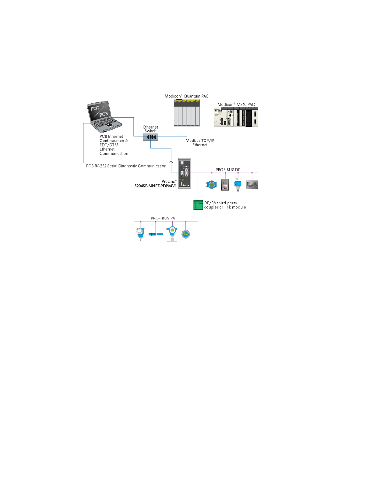
2.2 Architecture
The following diagram shows an example network that connects a Personal
Computer (PC) and a Modicon M340 or Quantum Programmable Automation
Controller (PAC) to a ProLinx 5204SE-MNET-PDPMV1 gateway.
You configure the gateway using ProSoft Configuration Builder (PCB) software
through an Ethernet connection. The gateway also uses its Ethernet port to
support the Modbus TCP/IP protocol, allowing it to communicate with the
Modicon processor, as well as other Modbus TCP/IP devices.
You ca n also use the Ethernet connec tion to manage your PRO FIBUS network
slaves using ProSoft Technology Field Device Tool/Communications Device
Type Manager (FDT/comDTM) drivers for popular plant asset management
software , such as P ACTware™ and Endress+Hauser FieldCare. For more
information on FDT/comDTM drivers for the gateway, please refer to the ProLinx
PDPMV1 Driver Manual, on the ProLinx Solutions CD-ROM.
The gateway's PROFIBUS port allows it to act as a PROFIBUS DP-V1 Master.
The special Application Communication Logic functions built into PCB create all
the Unity Pro Derived Data Types (DDTs), Variables, and Derived Function
Blocks (DFBs) needed by the Modicon processor to be able to send Modbus
TCP/IP messages and have those messages turned into PROFIBUS DP-V1
cyclic I/O and acyclic mailbox messages (called telegrams in the PROFIBUS
protocol). The gateway can also communicate with PROFIBUS PA slaves though
a third-party PROFIBUS DP-to-PA Link Coupler device (not supplied by ProSoft
Technology).
Page 10 of 235 ProSoft Technolo gy, Inc .
December 22, 2009
Page 11

Functional Overview 5204SE-MNET-PDPMV1 ♦ ProLinx Gateway
User Manual Modbus TCP/IP to PROFIBUS DP-V1 Pass-Through Master
The gateway has an RS-232 serial port. ProSoft Configuration Builder can use
this port to view the gateway's diagnostics and troubleshooting menus. You can
also use the serial port to upgrade the gateway's firmware.
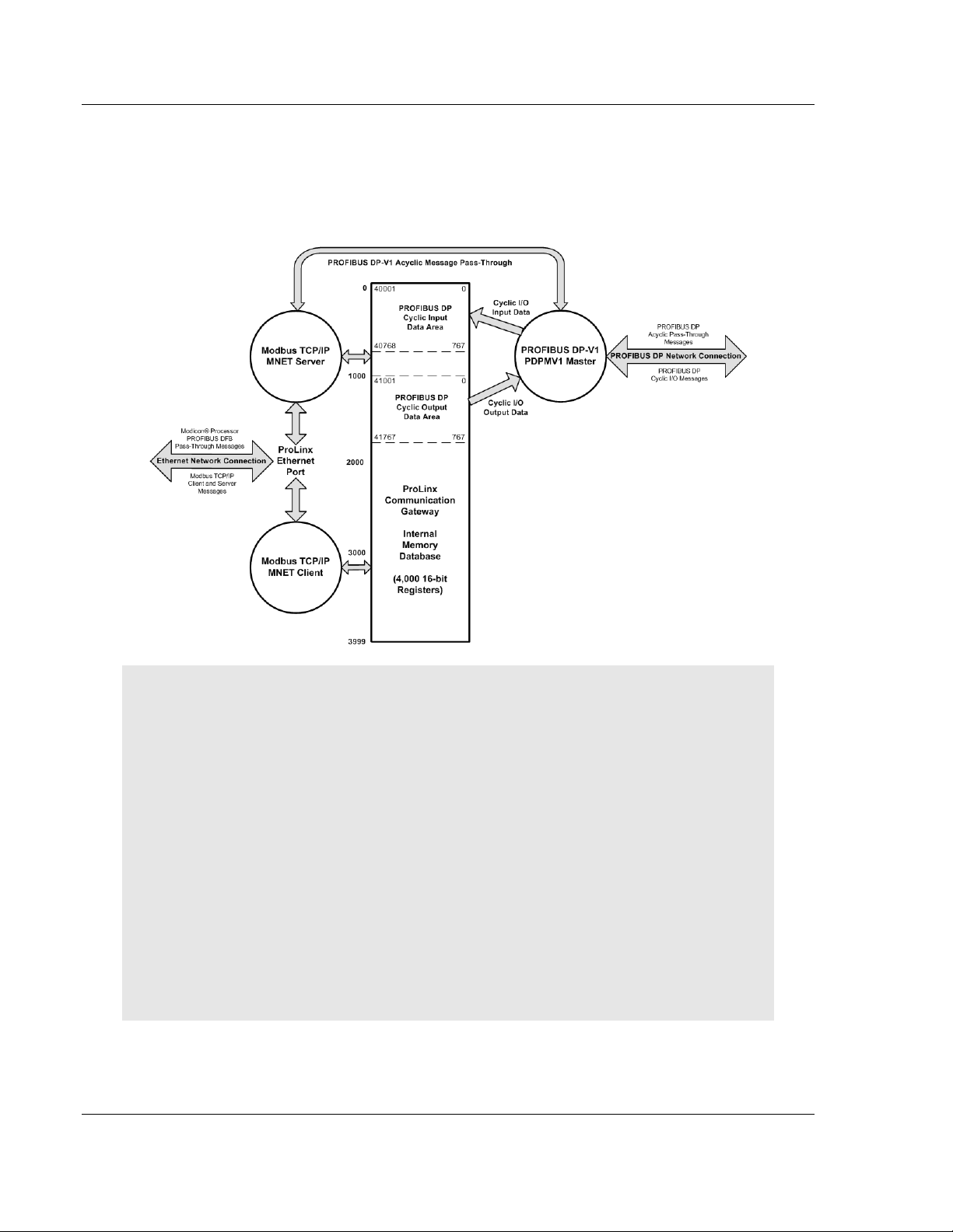
2.3 Data Flow throu gh the Gateway
The internal database is central to the functionality of the gateway. This database
is shared between all the ports on the gateway and is used as a conduit to pass
information from one devi ce on one networ k to on e or m or e devi c es on ei th er
network su pp or te d by t he gateway. This perm i ts d ata from dev ices on one
communication port or network to be viewed and control l ed by dev i c es on
another port or network. In addition to data from the Master port, status and error
information generated by the gateway can also be mapped into the internal
database.
This special SE implementation of the 5204SE-MNET-P DPMV1 gateway uses
the gateway database to store PROFIBUS DP cyclic input and output data. This
means this PROFIBUS cyclic data will be available to the MNET Client (Master)
and Server (Slave) drivers for use on a Modbus TCP/IP network. The SE version
of the MNET Server has also been programmed to "Pass-Through" special
PROFIBUS DP-V1 acyclic mailbox message commands from the Modbus
TCP/IP Server directly to the PDPMV1 PROFIBUS DP-V1 Master driver for
transmiss io n on th e PR OF I BU S network.
ProSoft Technolo gy, Inc . Page 11 of 235
December 22, 2009
Page 12
5204SE-MNET-PDPMV1 ♦ ProLinx Gateway Functional Overview
Modbus TCP/IP to PROFIBUS DP-V1 Pass-Through Master User Manual
This pass-through capability allows a Modicon processor using its native Modbus
TCP/IP protocol to communicate directly with PROFIBUS DP-V1 slaves and
receive their responses, if any. Pass-through functions bypass the gateway
database, going from Modicon processor to SE MNET Server to PDPMV1
Master to PROFIBUS DP slaves and back.
Note: The normal MNET Server driver will accept and respond normally to remote Modbus TCP/IP
Client requests to read or write data to any address in the gateway's internal database. However,
this special SE implementation of the MNET Server is slightly different.
The SE MNET Server will accept and respond to read requests from Modbus TCP/IP clients in the
same way as the normal MNET Server. However, for write requests, the SE MNET Server will
accept and respond normally only if the address or addresses to be written fall in the gateway
database area designated for PROFIBUS Cyclic Output Data. This area is internal addresses 1000
through 1767, which have corresponding virtual Modbus addresses of 41001 through 41768 (fivedigit addressing) or 401001 through 401768 (six-digit addressing), as shown in the preceding data
flow diagram.
Any write requests received by the special SE MNET Server that are outside this specific data
address range will be rejected by the SE Server and an exception response containing Exception
Code "02 ILLEGAL DATA ADDRESS" will be returned to the requesting Client.
This special modification has been done to preserve the integrity of PROFIBUS Input Data by
preventing external Modbus TCP/IP Clients from writing to and thereby corrupting data in this
critical area, while allowing any Modbus TCP/IP Client to send data to PROFIBUS slaves by writing
it to the PROFIBUS Output Data area.
Page 12 of 235 ProSoft Technolo gy, Inc .
December 22, 2009
Page 13
Functional Overview 5204SE-MNET-PDPMV1 ♦ ProLinx Gateway
User Manual Modbus TCP/IP to PROFIBUS DP-V1 Pass-Through Master
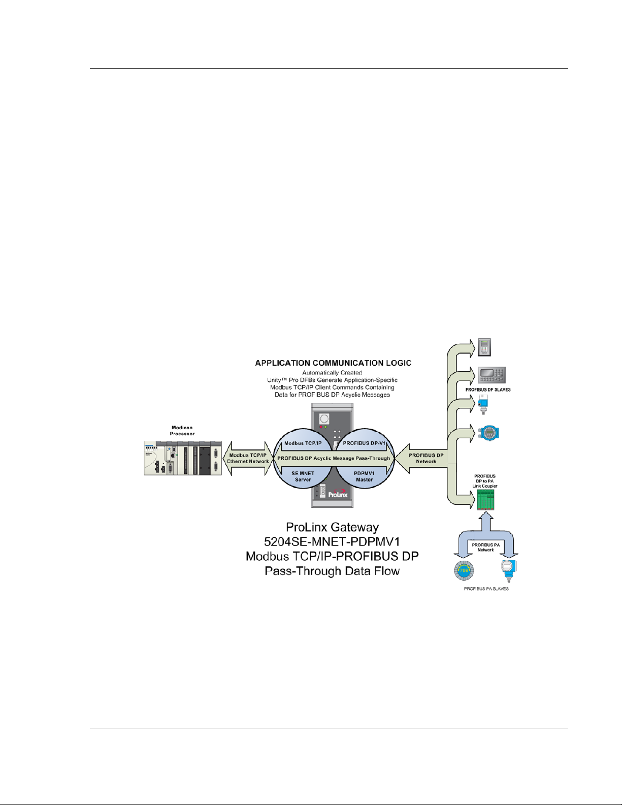
2.4 PROFIBUS DP Pass-Through Data Flow
The Application Communication Logic functions built into the latest version of
ProSoft Conf igu ration Bu ilde r (PCB) will automatically cre ate all the Derived Data
Types (DDTs), Variables, and Derived Function Blocks (DFBs) required by the
Modicon pr oc e ss or to al low it to act as a PROFIBU S DP-V1 Master for acy cl i c
mailbox message communication. PCB uses the PROFIBUS DP Master
configuration to create two files that may be imported into Unity Pro version 4.0
(or higher) to create these data structures and process logic.
PROFIBU S DP- V1 ac yc l ic com m uni c ati o n go es b eyond normal cycl i c I /O dat a
transfers by adding the capability to directly access each PROFIBUS network
slave. The types of acyclic data available varies from slave to slave but generally
include such data as alarm and status information, extended diagnostic
information, extended process data information, and device-specific special
commands.
The following illustration shows the basics of acyclic mailbox message data flow
from a Modicon processor, through the two gateway drivers, out to PROFIBUS
slaves, with responses (if any) returned to the Modicon.
ProSoft Technolo gy, Inc . Page 13 of 235
December 22, 2009
Page 14

5204SE-MNET-PDPMV1 ♦ ProLinx Gateway Functional Overview
Modbus TCP/IP to PROFIBUS DP-V1 Pass-Through Master User Manual
The DFBs create Modbus TCP/IP Client (Master) commands, which are
transmitted to the ProLinx MNET server (slave) driver. The MNET server
recognizes these special Modbus TCP/IP commands as PROFIBUS DP Acyclic
mailbox messages, strips out the PROFIBUS DP-V1 acyclic mailbox message
parameters contained in the Modbus TCP/IP message, and passes those
PROFIBUS message parameters through to the ProLinx PDPMV1 Master driver
for transmission to the PROFIBUS slave or slaves indicated in the message. Any
response message returned by the a slave to the PDPMV1 Master will be
automatically repackaged as a Modbus TCP/IP message and returned to the
Modicon processor, where the imported DFBs will process it.
This process allows a Modicon processor, using its native Modbus TCP/IP
communication ability, to act as a PROFIBUS DP-V1 Master on a PROFIBUS
network. By using a third-party PROFIBUS DP to PROFIBUS PA Link Coupler
(not supplied by ProSoft Technology), you can extend these PROFIBUS
capabilities even fu rther and communicate with PROFIBUS PA slaves.
2.5 Cyclic Polling and Acyclic Messaging Control Logic
The Application Communication Logic functions of ProSoft Configuration Builder
(PCB) automatically create Variables, DDTs and DFBs that have been
customized to match the PROFIBUS part of your PCB application. These
automatically-created structures and logic give you all the basic building blocks
you need to create an effective Modbus TCP/IP to PROFIBUS DP
communication appli c ation.
To complete your PROFIBUS communication application, all you will need to do
is to create your own customized control and sequencing logic to call the PCBgenerated DFBs in a logical, controlled manner. It will be your sequencing logic
that will decide when to call for PROFIBUS cyclic I/O data, status, and diagnostic
updates. Your logic will also decide if and when to trigger any acyclic messages
you may need to send.
To help you create your control and sequencing logic, here are a few principles
to keep in mind.
1 Once you have successfully created and downloaded your PROFIBUS
configuration to the 5204SE-MNET-PDPMV1 gateway, the PROFIBUS DPV1 Master driver will automatically begin and maintain no rmal PROFIBUS
cyclic I/O communications. PROFIBUS cyclic inputs and outputs will
constantly be updated on the PROFIBUS network with no action being
required from the processor. This means that PROFIBUS cyclic data
transfers are asynchronous and separate from whatever communication the
processor may or may not be doing between itself and the 5204SE-MNETPDPMV1 gateway.
Page 14 of 235 ProSoft Technolo gy, Inc .
December 22, 2009
Page 15

Functional Overview 5204SE-MNET-PDPMV1 ♦ ProLinx Gateway
User Manual Modbus TCP/IP to PROFIBUS DP-V1 Pass-Through Master
2 In order for the processor to 'see' any of the data being received from the
PROFIBUS slaves or to send any data to the PROFIBUS slaves, your control
and sequencing logic must initiate Modbus TCP/IP Client command
messages from the processor to the gateway by using the binary trigger
variabl es pr ovi d ed for each DFB. Th is requirement ap plies eq ually f or the
cyclic DFBs and for the acyclic DFBs. The main difference will be that the
DFBs to update cyclic data will most likely be triggere d much mo re often than
the acyclic DFBs are triggered. For additional details, see Sample Control
and Sequencing Logic for Cyclic Data Polling (page 113).
3 The basic communication cycle between the processor and the gateway is:
o User-created logic in the processor sends a Modbus TCP/IP command
message to th e gat ew ay by triggering one o f th e fourteen (14) provided
DFBs.
o The MNET Server driver on the gateway receives the command.
o The MNET Server driver processes the command.
o The MNET Server driver returns a Modbus TCP/IP response to the
processor.
o Some commands cause data to be returned, such as read commands.
Some commands, such as write commands, return only an
acknowledgement that the command was received and executed.
Commands sometimes fail. Any data or error response to a command
returned by the MNET Server will be available in the provided Variables or
DDTs after being placed there by the triggered DFB that initiated the
process cycle. User-created logic in the processor must process data or
errors received in the Modbus TCP/IP response, if any.
o If no Modbus TCP/IP response is received within the time value specified
in a Timeout variable, the triggered DFB will set a Message Error bit flag
to indicate the message sequence failed and should be retried by
triggerin g a new message cycle.
4 In cases where PROFIBUS cyclic I/O data, general gateway status, or
standard PROFIBUS slave diagnostic data are concerned, these read or
write requests from the processor are handled internally in the gateway and
are processed asynchronously from any PROFIBUS DP Master processes
that might also be running in the gateway. This means these cyclic requests
tend to be responded to much more quickly than requests involving acyclic
messages that must be "passed-through" to the PROFIBUS Master for
execution before a Modbus TCP/IP response can be created and returned to
the processor.
5 In cases where PROFIBUS DP-V1 acyclic messages are concerned, these
read or write requests require a longer, more involved process cycle,
synchronized with actions on the PROFIBUS DP-V1 Master side of the
module. When the processor sends a Modbus TCP/IP read or write request,
using an acyclic message DFB:
o User-created logic in the processor sends a Modbus TCP/IP command
message containing the data needed for the PROFIBUS DP-V1 acyclic
message to th e gateway by trigg er i ng one o f the ten ( 10) pr ovi d ed acyclic
DFBs.
o The gateway MNET Server must process the incoming command.
ProSoft Technolo gy, Inc . Page 15 of 235
December 22, 2009
Page 16

5204SE-MNET-PDPMV1 ♦ ProLinx Gateway Functional Overview
Modbus TCP/IP to PROFIBUS DP-V1 Pass-Through Master User Manual
o The MNET Server must pass the acyclic message and any associated
data through to the PROFIBUS DP-V1 Master.
o The PROFIBUS Master must insert this command in between normal
slave data polling messages (send an acyclic message to a particular
slave or group of slaves.)
o The PROFIBUS Master must receive a response from the addressed
PROFIBUS slave.
o The PROFIBUS Master must return any PROFIBUS slave response data
to the MNET Server.
o The MNET Server must create and return a Modbus TCP/IP response to
the processor containing the data, if any, from the PROFIBUS slave or
slaves.
o Some acyclic messages cause data to be returned. Some acyclic
messages return no data. Acyclic messages sometimes fail.
Communication failur es co ul d ha ppen on either or both the Modbus
TCP/IP protocol or the PROFIBUS protocol. Any data or error response to
an acyclic message returned by the PROFIBUS Master or the MNET
Server will be available in the provided Variables or DDTs after being
placed there by the triggered DFB that initiated the process cycle. User-
created logic in the processor must process data received in the
PROFIBUS DP or Modbus TCP/IP response, if any.
o If no Modbus TCP/IP response is received within the time value specified
in a Timeout variable, the triggered DFB will set a Message Error bit flag
to indicate the message sequence failed and should be retried by
triggerin g a new message cycle.
You can see from the amount of processing involved that it will take
somewhat more time for the gateway to respond to acyclic message
commands than it will take to respond to cyclic I/O, status and diagnostics
requests.
6 Due to the nature of the communication routines used in the processor and
the Unity Pro programming language, only one Modbus TCP/IP command
can be "active" or "in process" at any one time. All the provided DFBs hav e
internal checks built in to prevent more than one at a time from being active.
Therefore, any control or sequencing logic you create must respect and
accommo da te thi s pr ocessor/l an gu ag e li mi tation. Part o f the
accommodations you will have to make is to allow for the differing amounts of
time it takes to process cyclic I/O and status commands as well as the
increased time it takes to process acyclic messages.
7 All provided DFBs have binary status bits available which can be monitored
by your control and sequencing logic to be sure you are not trying to activate
more than on e DFB-created Modbus TCP/IP message at a time. There is a
Message Done bit to indicate the communication cycle completed
successfully; and, there is a Message Error bit to indicate the communication
cycle did not complete successfully.
Page 16 of 235 ProSoft Technolo gy, Inc .
December 22, 2009
Page 17

Procedures 5204SE-MNET-PDPMV1 ♦ ProLinx Gateway
User Manual Modbus TCP/IP to PROFIBUS DP-V1 Pass-Through Master
3 Procedures
In This Chapter
ProLinx Reference Guide...................................................................17
Install ProSoft Configuration Builder Software.....................................17
Set Module Parameters .....................................................................21
Confi g u re the Ga teway......................................................................23
Password Protecting the Module........................................................49
Configure the Modicon M340 Processor with Unity Pro .......................56
Configure the Modicon Quantum Processor with Unity Pro..................74
3.1 ProLinx Reference Guide
The ProLinx Reference Guide on the ProSoft Sol u ti ons CD- R OM provides
detailed information on the entire range of ProLinx modules. If you have any
questions that are not answered in the MNET-PDPMV1 User Manual, please
refer to the P roL inx Reference Guide.
3.2 Install ProSoft Configuration Builder Software
You must install the ProSoft Configuration Builder (PCB) software to configure
the gateway. You can always get the newest version of ProSoft Configuration
Builder from the ProSoft Technology web site.
To install ProSoft Configuration Builder from the ProSoft Web Site
1 Open your web browser and navigate to http://www.prosoft-
technology.com/pcb
2 Click the D
Configuration Builder .
3 Choose "S
4 Save the file to your Windows Desktop, so that you can find it easily when
you have fini s h ed dow nloading.
5 When t h e download is complete, locate and open the file, and then follow the
instructions on your screen to install the program.
OWNLOAD HERE link to download the latest version of ProSoft
AVE" or "SAVE FILE" when prompted.
If you do not have access to the Internet, you can install ProSoft Configuration
Builder from the ProSoft Solutions CD-ROM, included in the package with your
gateway.
ProSoft Technolo gy, Inc . Page 17 of 235
December 22, 2009
Page 18

5204SE-MNET-PDPMV1 ♦ ProLinx Gateway Procedures
Modbus TCP/IP to PROFIBUS DP-V1 Pass-Through Master User Manual
To install ProSoft Configuration Builder from the Product CD-ROM
1 Insert the ProSoft Solutions Product CD-ROM into the CD-ROM drive of your
PC. Wait for the startup screen to appear.
2 On the startup screen, click P
RODUCT DOCUMENTATION. This action opens a
Windows Explorer file tree window.
3 Click to open th e U
TILITIES folder. This folder contains all of the applications
and files you will need to set up and configure your gatewa y.
4 Double-click the S
"PCB_*.
EXE" file and follow the instructions on your screen to install the
ETUPCONFIGURATIONTOOL folder, double-click the
software on your PC. The information represented by the "*" character in the
file name is the PCB version number and, therefore, subject to change as
new versions of PCB are released.
Note: Many of the configuration and maintenance procedures use files and other utilities on the
CD-ROM. You may wish to copy the files from the Utilities folder on the CD-ROM to a convenient
location on your hard drive.
3.2.1 Using the Online Help
Most of the information needed to help you use ProSoft Configuration Builder is
provided in a Help System that is always available whenever you are running
ProSoft Configuration Builder. The Help System does not require an Internet
connection.
To view the help pages, sta r t ProSoft Configuration Buil der, open the H
menu, and then choose CONTENTS.
ELP
3.2.2 Using ProSoft Configuration Builder
ProSoft Configuration Builder (PCB) prov i d es a qu i ck and easy way to manage
gateway configuration files customized to meet your application needs. PCB is
not only a powerful s olution for ne w configuratio n files, but a lso allows you to
import information from previously installed (known working) configurations to
new projec ts .
Page 18 of 235 ProSoft Technolo gy, Inc .
December 22, 2009
Page 19
Procedures 5204SE-MNET-PDPMV1 ♦ ProLinx Gateway
User Manual Modbus TCP/IP to PROFIBUS DP-V1 Pass-Through Master
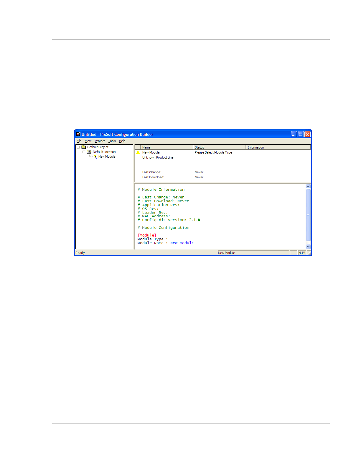
3.2.3 Set Up the Project - SE-MNET-PDPMV1
To begin, start ProSoft Configuration Builder. If you have used other Windows
configuration tools before, you will find the screen layout familiar. ProSoft
Configuration Builder’s window consists of a tree view on the left, an information
pane, and a configuration pane on the right side of the window. When you first
start ProSoft Configuration Builder, the tree view consists of folders for Default
Project and Default Location, with a Default Module in the Default Location
folder. The following illustration shows the ProSoft Configuration Builder windo w
with a new project.
Your first task is to add the 5204SE-MNET-PDPMV1 module to the project.
1 Use the mouse to select D
EFAULT MODULE in the tree view, and then clic k the
right mouse button to open a shortcut menu.
ProSoft Technolo gy, Inc . Page 19 of 235
December 22, 2009
Page 20
5204SE-MNET-PDPMV1 ♦ ProLinx Gateway Procedures
Modbus TCP/IP to PROFIBUS DP-V1 Pass-Through Master User Manual
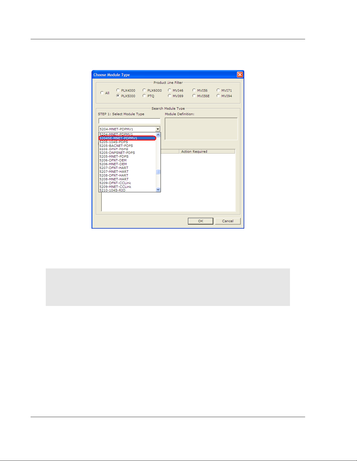
2 On the shortcut menu, choose C
C
HOOSE MODULE TYPE dialog box.
HOOSE MODULE TYPE. This actio n op ens the
3 In the P
S
ELECT MODULE TYPE dropdown list, select 5204SE-MNET-PDPMV1, and
then click OK
RODUCT LINE FILTER area of the dialog box, select 5204SE. In the
to save your settings and return to the PROSOFT
CONFIGURATION BUILDER window.
Important: Be sure to pick the 5204SE-MNET-PDPMV1 module from the list. The very similar
5204-MNET-PDPMV1 does not support the special Application Communication Logic functions
available in the 5204SE-MNET-PDPMV1. These functions are required to integrate the 5204SEMNET-PDPMV1 with the Modicon processor.
Page 20 of 235 ProSoft Technolo gy, Inc .
December 22, 2009
Page 21
Procedures 5204SE-MNET-PDPMV1 ♦ ProLinx Gateway
User Manual Modbus TCP/IP to PROFIBUS DP-V1 Pass-Through Master
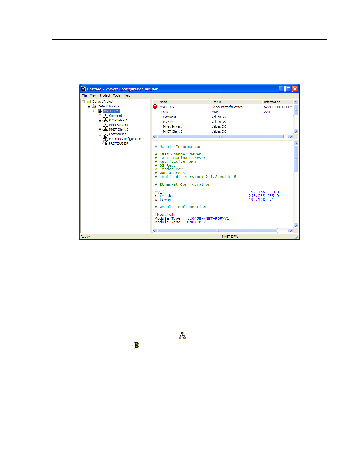
3.3 Set Module Parameters
Notice that the contents of the information pane and the configuration pane
changed when you adde d the 5204SE-MNET - PDPMV1 modul e to the project.
At this time, you may wish to rename the "Default Project" and "Default Location"
folders in the tree view.
To rename an object:
1 Select the object, and then click the right mouse button to open a shortcut
menu. From the shortcut menu, choose R
ENAME.
2 Type the name to assi gn to the object.
3 Click away from the object to save the new name.
3.3.1 To Configure Module Parameters
1 Click on the plus sign next to the icon to expand gateway information.
2 Double-click the
3 To edi t a parameter , select the parameter in the left pane and make your
changes in the right pane.
4 Click OK
to save your changes.
icon to open the EDIT dialog box.
ProSoft Technolo gy, Inc . Page 21 of 235
December 22, 2009
Page 22

5204SE-MNET-PDPMV1 ♦ ProLinx Gateway Procedures
Modbus TCP/IP to PROFIBUS DP-V1 Pass-Through Master User Manual
3.3.2 Printing a Configuration File
1 Select the MODULE icon, and then click the right mouse button to open a
shortcut menu.
2 On the shortcut menu, choose V
V
IEW CONFIGURATION window.
3 On the V
P
RINT. This action opens the PRINT dialog box.
4 On the P
select printing options, and then click OK.
IEW CONFIGURATION window, open the FILE menu, and choose
RINT dialog box, choos e th e printer to use from the dr o pd ow n lis t ,
IEW CONFIGURATION. This action opens the
Page 22 of 235 ProSoft Technolo gy, Inc .
December 22, 2009
Page 23

Procedures 5204SE-MNET-PDPMV1 ♦ ProLinx Gateway
User Manual Modbus TCP/IP to PROFIBUS DP-V1 Pass-Through Master
3.4 Configure the Gateway
To configure the gateway for your application, follow these steps:
1 Configure the PROFIBUS DP Master Setting and setup all PROFIBUS DP
network slave devices (page 23, page 24)
2 Configure the PROFIBUS Master DP-V1 gateway settings (page 32)
3 Configure the MNET Server Settings (Optional - default settings can be used
without modificati on) (page 38)
4 Configure the MNET Client Settings (Optional - default settings can be used
without modificati on) (page 39)
5 Configure the Ethernet Settings (page 40)
6 Download the Project to the gateway (page 43).
3.4.1 Configure the PROFIBUS DP Network
To configure your PROFIBUS DP network you must perform four tasks:
1 Install any PROFIBUS slave-specific device configuration files, typically
called .GSD files (p age 23).
2 Configure the ProLinx PROFIBUS DP Master (page 23, page 24).
3 Configur e the PROF I BU S Sl av es .
4 Print the Unity Passthru Memory Map (page 30).
Install the GSD Files
ProSoft Con fi guration Buil d er (PCB) us es PROF IBUS slave devi ce definition files
(GSD files) to obtain basic configuration information about the PROFIBUS slaves
you add to the network. The GSD configuration files identify the slave’s
capabilities so that the 5204SE-MNET-PDPMV1 ca n communicate with it
correctly.
Follow these steps to install the GSD file or files for your slave device or devices.
Tip: GSD configuration files for popular PROFIBUS slaves and ProSoft Technology solutions are
included with PCB. Before installing GSD files, browse the list of available slaves in the Tree View
window to see if GSD files for your slave are already installed.
GSD files are often both model number specific as well as model revision specific. Just because
you may have an older GSD file from a manufacturer for the particular make and model of your
slave device does not guarantee it will work for a newer revision of that device. Be sure you obtain
from the device manufacturer the correct GSD file or files for your PROFIBUS slave or slaves.
To install GSD files manually:
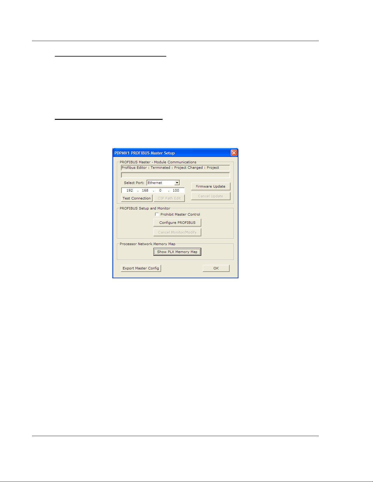
1 In ProSoft Configuration Builder tree view, click [+] to expand the module
tree, and then double-cl ic k t he PROFIBUS
DP icon. This action opens the
PDPMV1 PROFIBUS Master Setup dialog box.
2 Click the C
ONFIGURE PROFIBUS button. This action opens the ProSoft
Configuration Builder for PROF IBUS applicati o n.
ProSoft Technolo gy, Inc . Page 23 of 235
December 22, 2009
Page 24
5204SE-MNET-PDPMV1 ♦ ProLinx Gateway Procedures
Modbus TCP/IP to PROFIBUS DP-V1 Pass-Through Master User Manual
3 Open the T
OOLS menu, and then choose INSTALL NEW GS* FILE. This action
opens a dialog box that allows you to browse for the location of the GSD
configuration files to install. (Depending on the device and language used in
the file, the actual extension may be ".GSD", ".GSE", ".GSS", of other
combinations; hence the generic reference to ".GS*" files, where "*" is a
wildcard that stands for any letter.)
4 Choose the file to install, and then click O
PEN. If the fil e alr e ady exi s ts in the
configuration file path, you will be prompted to overwrite the file.
5 You will be prompted to associate the GSD configuration file with a bitmap
image of the slave device. Use the F
ILE / OPEN dialog box to brow se for the
location of the image file to use. If you have no device-specific bitmap file,
you may C
the Bus Configuration window for this sla ve device.
ANCEL the bitmap upload, and a gene ric device icon will be used in
Configure the PROFIBUS DP Master
1 In ProSoft Configuration Builder tree view, click [+] to expand the module
tree, and then double-cl ic k t he PROFIBUS
DP icon. This action opens the
PDPMV1 PROFIBUS Master Setup dialog box.
2 On the PDPMV1 PROFIBUS Master Setup dialog box , cli c k t he C
ONFIGURE
PROFIBUS button. This action opens the ProSoft C onfiguration Bui l der for
PROFIBUS ap pl i cati o n.
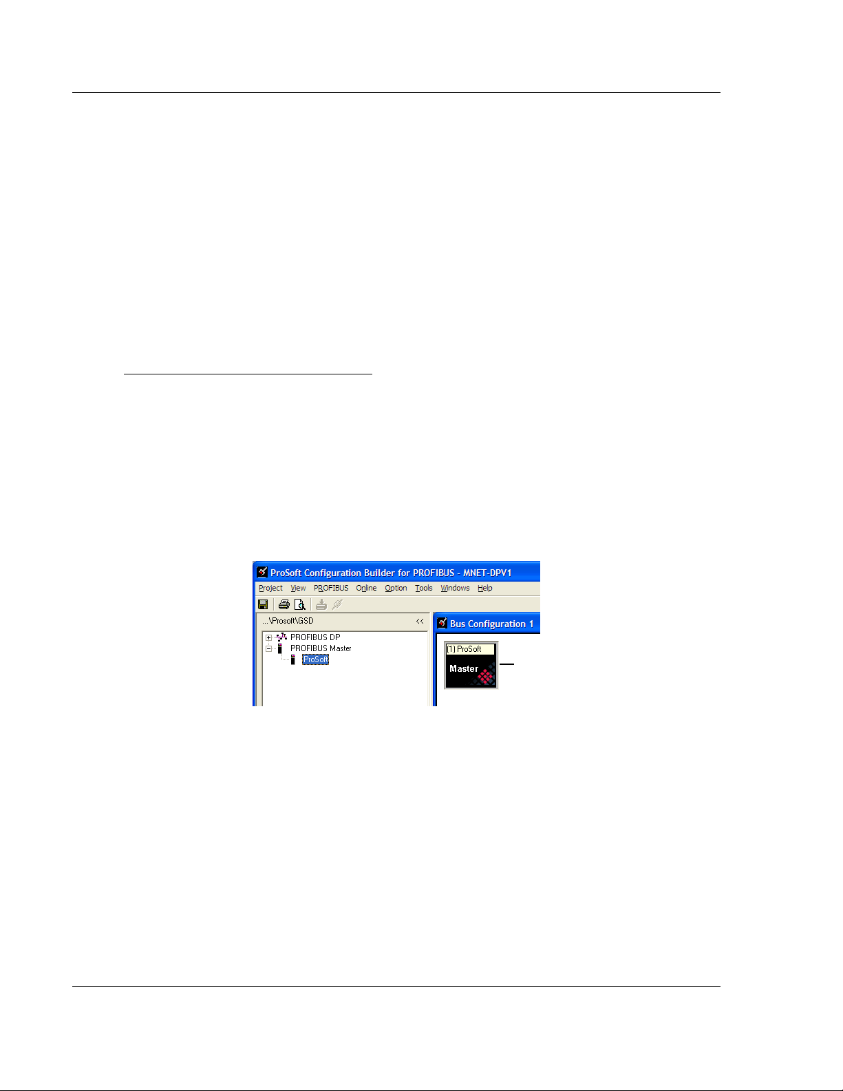
3 Click [+] to expand the PROFIBUS
4 Drag the P
ROSOFT PROFIBUS Master icon into the Bus Configuration
MASTER tree.
window.
Page 24 of 235 ProSoft Technolo gy, Inc .
December 22, 2009
Page 25
Procedures 5204SE-MNET-PDPMV1 ♦ ProLinx Gateway
User Manual Modbus TCP/IP to PROFIBUS DP-V1 Pass-Through Master
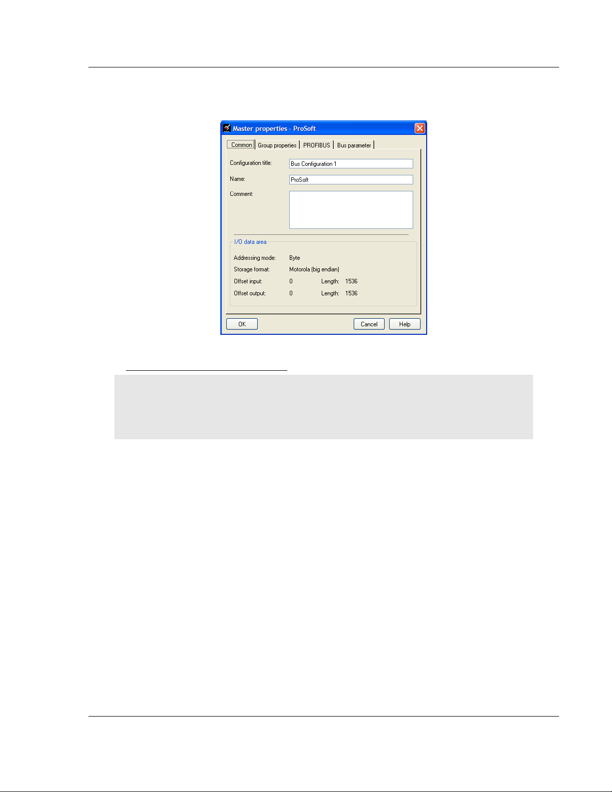
5 Double-click the P
ROSOFT MASTER icon in the Bus Configuration window.
This action opens the Master Properties di al o g bo x .
Configur e the PROF I BU S Sl aves
Important: The GSD file for this example is not included on the ProLinx Solutions CD-ROM, and is
used for illustrative purposes only. You can download a variety of example GSD files from the
PROFIBUS Trade Organization web site at www.profibus.org, or from the manufacturer's web site
for your PROFIBUS slaves.
The followi n g steps, descri be how to add and configure a Sieme ns EM 277 I/O
chassis to the PR OF I BU S network. The con fig ur at i on infor m a ti on (.GSD file) for
this device must be installed according to the procedure found in Install the GSD
Files ( page 23). Most other PROFIBUS Slaves can be configure d in a simi l ar
manner.
1 In ProSoft Configuration Builder for PROFIBUS, click the plus sign [+] to
expand the PROFIBUS
DP tree.
ProSoft Technolo gy, Inc . Page 25 of 235
December 22, 2009
Page 26
5204SE-MNET-PDPMV1 ♦ ProLinx Gateway Procedures
Modbus TCP/IP to PROFIBUS DP-V1 Pass-Through Master User Manual
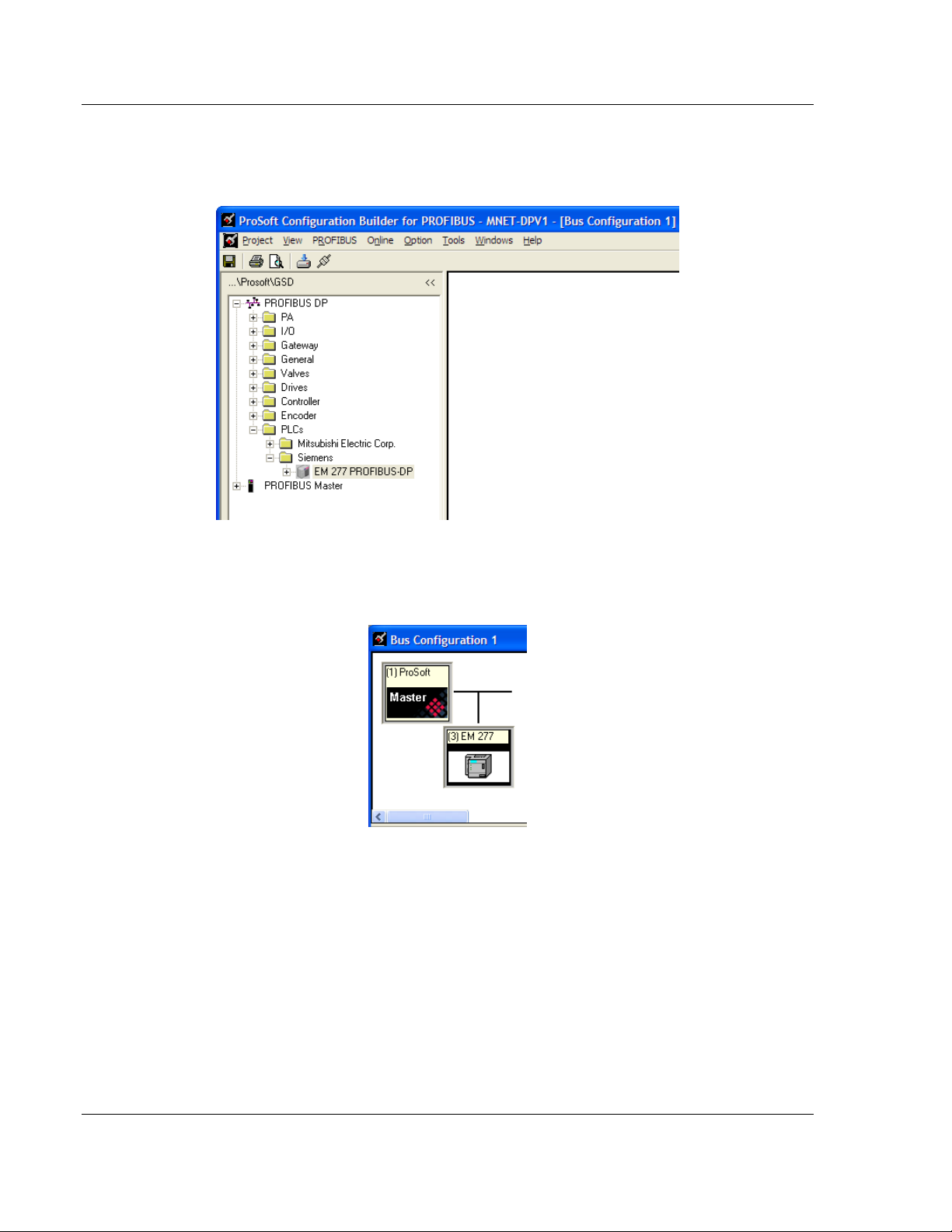
2 Navigate to the folder containing the type of slave device to add
(PLC
S/SIEMENS/EM 277, in this example), and then click the plus sign [+] to
expand the folder.
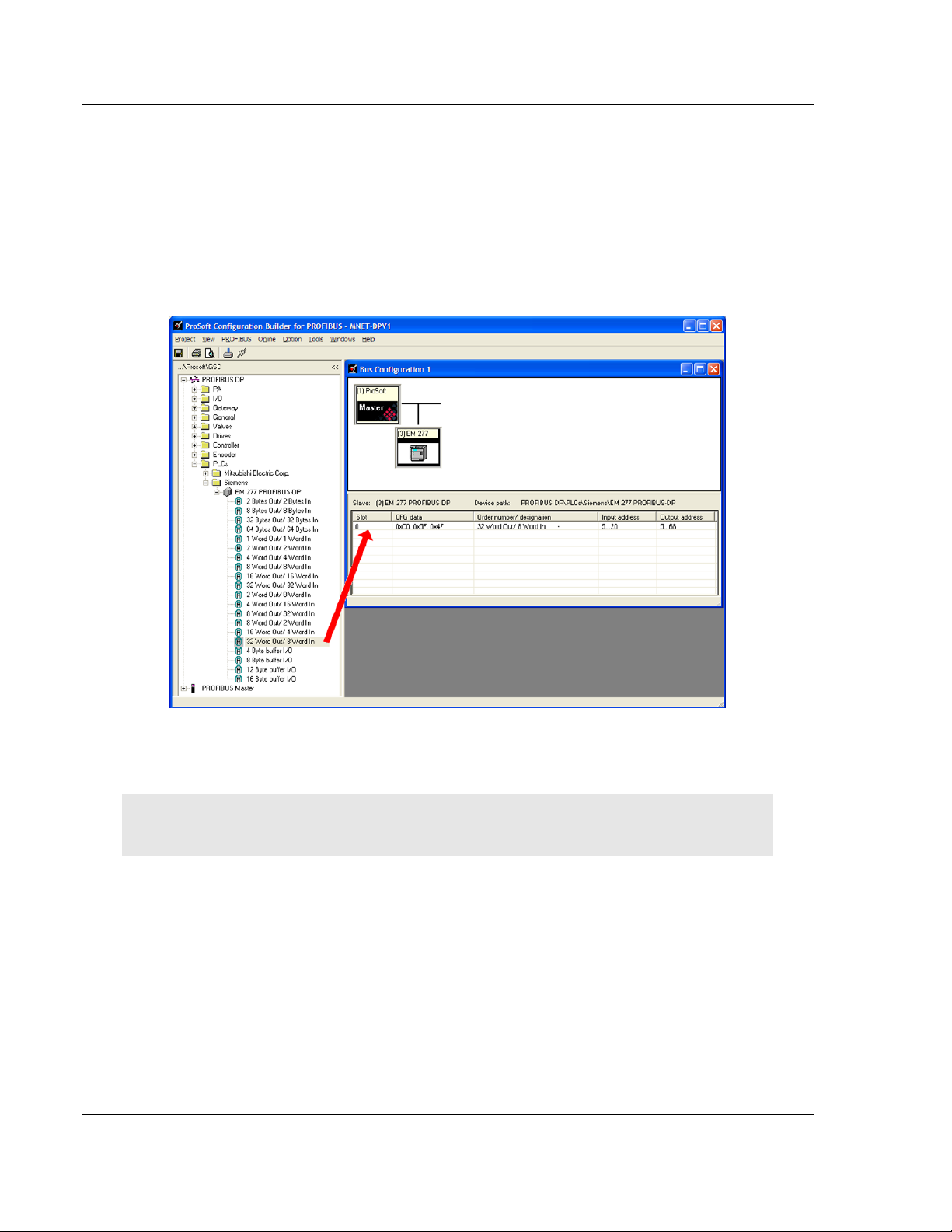
3 Click on the
EM 277 PROFIBUS-DP icon in the tree view and drag and drop
the icon into the Bus Configuration view. This action adds the slave device
and connects it to the Master in a network relationship.
Page 26 of 235 ProSoft Technolo gy, Inc .
December 22, 2009
Page 27
Procedures 5204SE-MNET-PDPMV1 ♦ ProLinx Gateway
User Manual Modbus TCP/IP to PROFIBUS DP-V1 Pass-Through Master
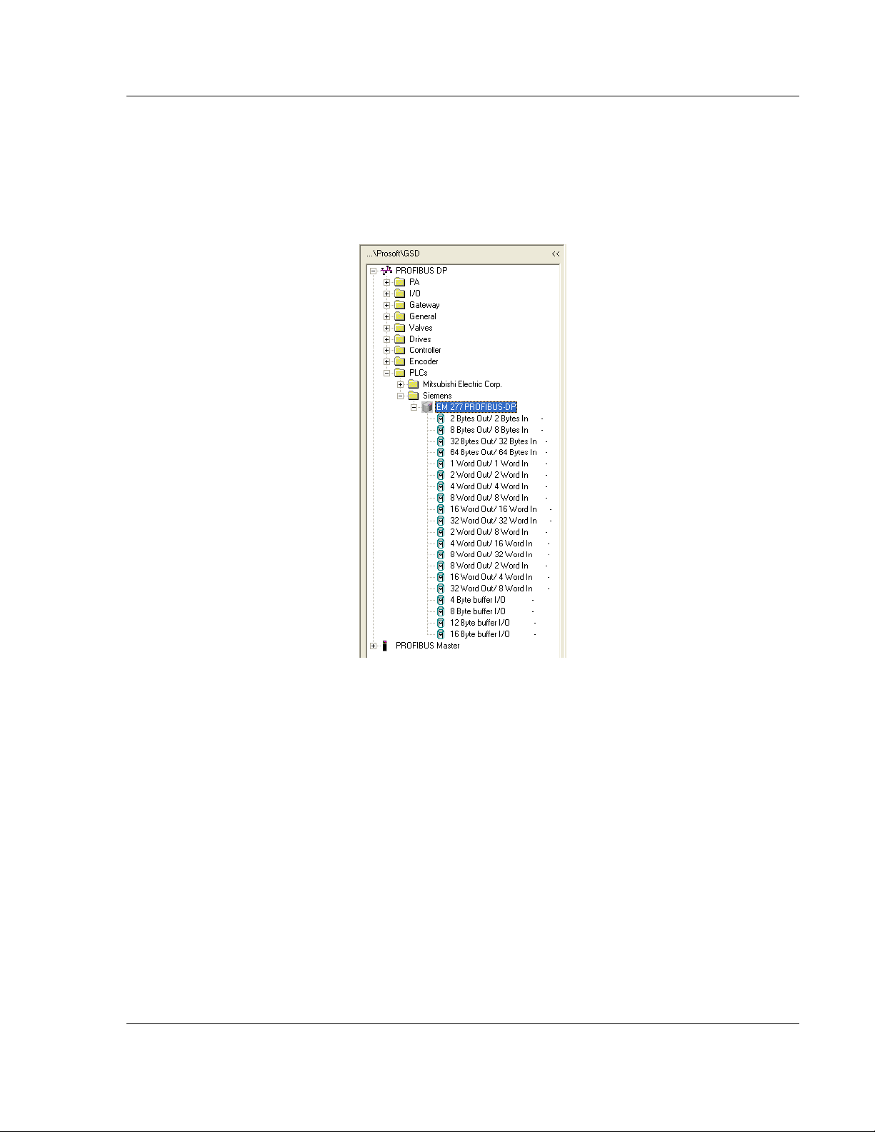
4 In the tree view, click the plus sign [+]
to expand the slave device you adde d.
This action opens a list of device configuration values. The following
illustration shows the possible input/output configuration values for a Siemens
EM 277. The selections available for other devices may be different, so you
should review the specifications for the pro duc t you a re insta lling in order to
determine the correct values to use.
ProSoft Technolo gy, Inc . Page 27 of 235
December 22, 2009
Page 28
5204SE-MNET-PDPMV1 ♦ ProLinx Gateway Procedures
Modbus TCP/IP to PROFIBUS DP-V1 Pass-Through Master User Manual
5 Drag the input and output parameters to the slot location grid (Subscriber
List) below the Bus Configuration window. The slot view displays the slot
number, c on fi guration data, and input and out put addresse s. T he PR OFIBUS
DP Master uses this information to identify and communicate with individual
slaves on the ne tw or k.
For this example, we will configure 8 words of input and 32 words of output.
These input and output words are assigned to addresses within the
gateway's internal database.
For each new slave added to the PROFIBUS network, ProSoft Configuration
Builder automatically converts the input/output byte addresses to word
input/output addresses.
Tip: To make it easier to view the data from individual slaves, you can create a spreadsheet with
all added slaves and input and output data offsets, or you can view and print the data map.
Page 28 of 235 ProSoft Technolo gy, Inc .
December 22, 2009
Page 29
Procedures 5204SE-MNET-PDPMV1 ♦ ProLinx Gateway
User Manual Modbus TCP/IP to PROFIBUS DP-V1 Pass-Through Master
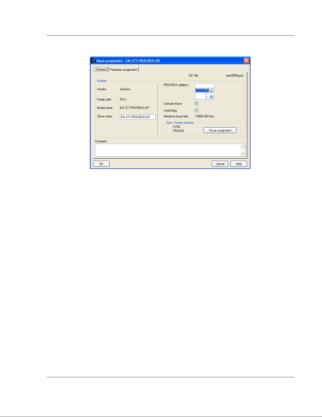
6 Double click the S
LAVE icon to view the Slave properties dialog.
ProSoft Configuration Builder automatically assigns a PROFIBUS address to
each new slave. The slave address assignment begins at address 3 for the
first slave added to the network (addresses 0, 1, and 2 are reserved for use
with PROFIBUS Masters), and is incremented by 1 for each new slave added
to the network. You may, however, assign any address, 0-125 to any Master
or slave node as long as you do not assign the same address to more than
one device. You can change the address in the C
OMMON tab of the Slave
properties dialog box. ProSoft Configuration Builder will not allow you to
assign a PROFIBUS address that is already in use by another device on this
network.
Leave the remaining settings unchan ge d for now , an d cli c k OK
to close the
Slave properties di al o g box.
7 Repeat steps 2 through 6 for all slaves you intend to place on the network.
8 When yo u are f inished adding slave s, open the P
E
XIT. Click YES to save the project and retur n to the PROFIBUS Master Setup
dialog box.
ROJECT menu and choos e
ProSoft Technolo gy, Inc . Page 29 of 235
December 22, 2009
Page 30
5204SE-MNET-PDPMV1 ♦ ProLinx Gateway Procedures
Modbus TCP/IP to PROFIBUS DP-V1 Pass-Through Master User Manual
Print the Unity Passthru Memory Map
The Unity Passthru Memory Map dialog box uses the information about your
PROFIBUS Master and slave configuration to display where the data may appear
in your Modicon processor's Memory Word (%MW) data registers. You need to
know where in the Modicon processor %MW area you want the PROFIBU S da ta
to appear before you will be ab le to input configuration parameters that will make
this Memory Map display valid addresses.
To view or print the ProLinx Memory Map
1 On the PDPMV1 PROFIBUS Master Setup dialog box , cli c k t he
SHOW PLX
MEMORY MAP button, near the bottom of the window.
Page 30 of 235 ProSoft Technolo gy, Inc .
December 22, 2009
Page 31

Procedures 5204SE-MNET-PDPMV1 ♦ ProLinx Gateway
User Manual Modbus TCP/IP to PROFIBUS DP-V1 Pass-Through Master
This action opens Unity Pa s sthru Memory Map window.
2 Notice that there are two radio buttons in the Display ar ea o f the di al o g box to
select Inputs or Outputs. These Input and Output maps correspond to the
Input and Output data you configured for the PROFIBUS Slaves (page 25).
Notice also that there are check boxes to display
PROFIBUS
3 Click P
ADDRESSES.
RINT to print the maps for reference. Note that you must do this once
SLOT NUMBERS and
for the input map and once for the output map. Use the Display area radio
buttons to select which map you wish to print.
4 When yo u have finish ed printing th e ProLinx memory maps, click OK
the dialog box. Click OK
again to close the Master Setup dialog box.
to close
ProSoft Technolo gy, Inc . Page 31 of 235
December 22, 2009
Page 32

5204SE-MNET-PDPMV1 ♦ ProLinx Gateway Procedures
Modbus TCP/IP to PROFIBUS DP-V1 Pass-Through Master User Manual
3.4.2 [Profibus Master DPV1]
1 Click the plus sign [+] next to the modu le to exp and the module tr ee, and
then expand the PLX
PDPM-V1 tree.
2 Double-click the PROFIBUS
dialog box.
MASTER DPV1 object. This action opens the Edit
Page 32 of 235 ProSoft Technolo gy, Inc .
December 22, 2009
Page 33

Procedures 5204SE-MNET-PDPMV1 ♦ ProLinx Gateway
User Manual Modbus TCP/IP to PROFIBUS DP-V1 Pass-Through Master
PLC Input Start Register
The value you enter here will be used by PCB to assign Modicon processor's
%MW memory addresses to the Unity Passthru Input Memory Map.
Valid values are %MW address 000 01 to hi g hest possibl e ad dr es s ( 32 000 minus
NPUT DATA SIZE value, depending on the processor's memory configuration.)
I
Set this parameter to the Unity Pro M emory Word (%MW) address in the
Modicon processor that will hold PROFIBUS Slave device cyclic input data. This
start addr ess an d the I
NPUT DATA SIZE value will determine the area of processor
memory to reserve exclusively for incoming PROFIBUS cyclic input data.
Caution: To avoid corruption of PROFIBUS data, you must make sure that this memory area is
only read from and never written into by other parts of your application logic. Refer to the Unity
Passthru Memory Map for the addresses to use (page 30).
PROFIBUS cyclic input data will always be stored in the gateway's memory
addresses 0000 through 0767. These are 16-bit word-sized registers, which can
hold two (2) 8-bit bytes per register, for a total PROFIBUS cyclic input capacity of
1536 bytes .
Input Data Size
0 to 768
Total num ber of PROFIBUS Input Wor ds (one word eq uals two bytes) from all
PROF IBUS s laves. These Input Words will be the data received from slave
devices on the PROFIBUS network.
PLC Output Register Start
The value you enter here will be used by PCB to assign the processor's %MW
memory add res s es to the Unity Passthru Output Memory Map.
Valid values are %MW address 000 01 to hi g hest possibl e ad dr es s ( 32 000 minus
O
UTPUT DATA SIZE value, depending on processor memory configuration.)
Set this parameter to the Unity Pro Memory Word (%MW) address in the
processor you intend to use for holding PROFIBUS slave device cyclic output
data. This start address and the O
UTPUT DATA SIZE value will determine the area
of processor memory to reserv e exc l u si vel y for ou tgoing PROFIBUS cyc l ic outp ut
data. Be sure other parts of your application logic put data into this area only if it
should be sent to PROFIBUS slaves and be sure to put the data into the correct
part of this data ar e a, so tha t the da ta goes to the correct slav e .
For more information on using these me mory reg isters, refer to Print the Unity
Passthru Memory Map (page 30).
You will need to create your own custom control and sequencing logic to place
data into the proper places in the processor memory in this address range before
you send the data to the gateway with the WriteCyclicData DFB.
ProSoft Technolo gy, Inc . Page 33 of 235
December 22, 2009
Page 34

5204SE-MNET-PDPMV1 ♦ ProLinx Gateway Procedures
Modbus TCP/IP to PROFIBUS DP-V1 Pass-Through Master User Manual
PROFIBUS cyclic output data will always be stored in the gateway's memory
addresses 1000 through 1767. These are 16-bit word-sized registers, which can
hold two (2) 8-bit bytes per register, for a total PROFIBUS cyclic output capacity
of 1536 byt es.
Warning: Inadvertant overwriting of data in the PROFIBUS memory areas could cause
unexpected behavior on your PROFIBUS DP network, leading to unintended equipment operation.
Such unintended operation could cause injury to personnel or damage to equipment.
Output Data Size
0 to 768
Total num ber of PROFIBUS Output Words (one word equals two bytes) to be
sent to all PROFIBUS Slaves. These Output W ords will be the data sent to Slave
devices on the PROFIBUS network.
Input Byte Swap
Yes or No
This paramete r determines if the bytes in the PROFIBUS Input Dat a area are
swapped before being stored in the gateway memory database. If the parameter
is set to N
O, no swapping will be applied. If the parameter is set to YES, the o r der
of bytes in each word will be swapped before being stored in memory.
Example:
With Input Byte Swap set to N
With Input Byte Swap set to Y
O, incoming order is unchanged - ABCDEF
ES, each byte pair is swapped - BADCFE
Output By te Swap
Yes or No
This paramete r determines if the bytes in the PROFIBUS Output Data ar ea are
swapped before being transmitted to slaves on the PROFIBUS network. If the
parameter is set to N
Y
ES, the order of bytes in each word will be swapped before bein g tran smitted.
O, no swapping will be applied. If the parameter is set to
Example:
With Output Byte Swap set to N
O, outgoing output order is unchanged -
ABCDEF
With Output Byte Swap set to Y
BADCFE
ES, each output byte pair is swapped -
Page 34 of 235 ProSoft Technolo gy, Inc .
December 22, 2009
Page 35

Procedures 5204SE-MNET-PDPMV1 ♦ ProLinx Gateway
User Manual Modbus TCP/IP to PROFIBUS DP-V1 Pass-Through Master
Mailbox Messaging
Yes or No
This parameter controls whether or not special files will be created for import into
your Unity Pro project for PROFIBUS acyclic messaging support.
Set the param eter to Y
capabilities of PROFIBUS DP versio n 1. When set to Y
ES if you plan to use the special acyclic messaging
ES, the gateway will use
your PROFIBUS DP Master/Slave configuration to create the required Derived
Function Blocks (DFBs), Derived Data Types (DDTs), and Variables ne eded for
process or ap pl i cati o n l ogi c.
If your PROFIBUS application uses only cyclic I/O data (PROFIBUS Input and
Output Data) and you will not be using any acyclic messaging, set this parameter
to N
O, so that unnecessary files will not be created.
Slav e Diagnostics
Yes or No
If the parameter is set to Y
ES, then the gateway will poll data from all slaves on
the PROFIBUS network and place it in the gateway database addresses1800
through 2177. If it is set to N
O, then the gateway will not poll any slave
diagnostics data over the network and the gateway database will show zeros in
this area.
Each PROFIBUS slave can report six bytes (three words) of standard diagnostic
data. A total of 378 words (756 bytes; 3 words or 6 bytes times 126 possible
nodes) will have to be reserved to ho ld this Slave D i agn osti c Data in processor
%MW memory to use this feature.
PLC Status Data Register Start
Modicon %MW address 00001 to highest possible address (32000 minus 152).
Set this parameter to the Unity Pro Memory Word (%MW) address in the
processor that you intend to use for holding general gateway status data. This
data consists of 76 words (152 bytes) of gateway status registers, error counters,
and general gateway diagnostic information. This start address will determine the
area of the processor memory to reserve exclusively for incoming gateway status
data. Be sure this memory area is only read from and never written into by other
parts of your application logic to avoid corruption of this status data.
General gateway status data will always be stored in the gateway's memory
addresses 2200 through 2275. For more details about the contents of these
registers, refer to DFB Get Module Status (page 109).
ProSoft Technolo gy, Inc . Page 35 of 235
December 22, 2009
Page 36

5204SE-MNET-PDPMV1 ♦ ProLinx Gateway Procedures
Modbus TCP/IP to PROFIBUS DP-V1 Pass-Through Master User Manual
Watchdog Reg ister
The Watchdog function allows the gateway to monitor a database register, the
Watchdog Reg ister, to check for loss of communication with the non-PROFIBUS
communication prot ocol . If this fu ncti o n is used, the other gateway protocol is
expected to change the va lue in the Watchdog Register at an interval less than
the amount of time specified in the Watchdog T i me out parameter. If the value in
the Watchdog Register does not change within this amount of time, a
communication loss is assumed and the Watchdog function will set the
PROFIBUS outputs to the default value specified in the Watchdog Reset Value
parameter. To disable this function, set this parameter to a value of -1.
Watchdog Timeout
Sets the period of time (in 0.1s increments) for the gateway to wait for
communication loss detection. For example, set this parameter to 100 to set a
waiting period of 10 seconds. To disable this function, set this parameter to a
valu e of -1.
Watchdog Reset Value
Sets the value that will be sent to the PROFIBUS output byte registers upon
communication loss as detected by the Watchdog function. To disable this
function, set this parameter to a value of -1.
PLC Control Buffer Start
0 for M340 processors only
1 to 32000 for Quantum proces sor s onl y
This parameter serves two purposes. First, it tells the gateway what kind of
processor will be used. This affects what kind of export files are created by the
Application Communication Logic (ACL) features of the gateway. If set to zero
(0), export files will be created f or M340 processors. If set to a non-zero value in
the range of 1 to 32000, export files will be created for Quantum processors.
Second, it tells the gateway what addresses to show in the Unity Passthru
Memory Map for Quantum communication control and data buffers when a
Quantum processor is used.
Set this parameter to zero (0 ) when the module will be used with an M340
processor, which does not require special communication control and data buffer
space be reserved in proces sor memory. No Control Buffer information will be
shown in the Unity Passthru Memory Map when this parameter is set to zero (0).
Page 36 of 235 ProSoft Technolo gy, Inc .
December 22, 2009
Page 37

Procedures 5204SE-MNET-PDPMV1 ♦ ProLinx Gateway
User Manual Modbus TCP/IP to PROFIBUS DP-V1 Pass-Through Master
Set this parameter to a memory address (1 to 32000) to reserve memory space
in a Quantum processor for communication control and data buffers. To send
and receive Modbus TCP/IP messages with a Quantum processor, an area of
processor memory must be set aside and reserved for exclusive use as
communicat ion control and data buffer space. The am ount of memory that must
be reserved varies with the amount of communication tasks in the Unity Pro
program. The address you enter in this parameter will be the starting address of
these buffer s i n %MW pr ocessor memor y.
How much memory to reserve depends on whether or not you plan to use the
PROFIBUS Acyclic Messaging (Mailbox Messaging) capabilities of the gateway.
The commu ni cation control an d dat a bu ffer s ar e rel ated to the speci al Defined
Function Blocks (DFBs) created for you by the gateway's ACL. The four (4) basic
DFBs used to transfer PROFIBUS Cyclic data, general module status, and
standard slave diagnostic data require 436, 16-bit registers of communication
control and data buffer space. This is the least amount of space that will need to
be reserved. The ten (10) DFBs used to accomplish Mailbox Messaging require
as much as an addi ti o nal 16 35 regi s t ers , for a total of up to 2071 re gis ter s, that
should be reser v ed for th es e sp ec ial function buffers .
How you set the M
AILBOX MESSAGING parameter will determine ho w much
memory will be shown for Con trol Buffers in the Unity Passthru Memory Map.
Setting M
Buffers. Setting M
for Control Buffers.
AILBOX MESSAGING to NO will show 436 registers re served for Con trol
AILBOX MESSAGING to YES will show 2071 registers reserved
ProSoft Technolo gy, Inc . Page 37 of 235
December 22, 2009
Page 38

5204SE-MNET-PDPMV1 ♦ ProLinx Gateway Procedures
Modbus TCP/IP to PROFIBUS DP-V1 Pass-Through Master User Manual
3.4.3 Configure the MNET Server Settings (Optional)
All 4000 of the gateway's 16-bit internal memory registers can be read by remote
Modbus TCP/IP Clients. The gateway database registers can be read by remote
Modbus TCP/IP Clients (Masters) using virtual Modbus addresses 40001 through
44000 (for five-digit addressing) or 400001 through 404000 (for six digit
addressing).
However, not all 4000 registe rs can be written with Modbus TCP/IP write
requests from re mote Clie nt s. To maintain compatibility with the PRO FIBUS DPV1 Master protocol on this gateway, the MNET Server accepts write requests
from Clients only if the register address and range (count) used in the command
will place data in the PROFIBUS Output data area. This is the gateway database
area that holds data which will be sent to Slaves on the PROFIBUS DP network.
The allowable range of Modbus TCP/IP addresses for acceptable write requests
is 41001 through 41768 (fo r five-d igit addressing) or 4010 01 through 401768 (for
six-digit addressing). This address range is equivalent to the gateway's database
registers 1000 through 1767.
Care must be taken if remot e Clients are allowed to write to this data area
because, once data values are written into those registers, those data values will
be passed to PROFIBUS slaves. Which slave or slaves receive the data will be
determined by the PROFIBUS Master/slave configuration.
The default values contained in MNET Ser vers section of PCB should work for
most applications and should not need to be modified. If you wish to view the
MNET Server settings, you may do so by expanding the MNet Servers section of
the gateway configuration tree.
Page 38 of 235 ProSoft Technolo gy, Inc .
December 22, 2009
Page 39

Procedures 5204SE-MNET-PDPMV1 ♦ ProLinx Gateway
User Manual Modbus TCP/IP to PROFIBUS DP-V1 Pass-Through Master
3.4.4 Configure the MNET Client (Optional)
MNET Client Commands can affect the data contained in any of the gateway's
4000-register inte rnal memory da taba s e. Be awa re that the processor logic will
also be reading from and writing to the PROFIBUS areas of the gateway's
memory through the MNET Servers. If you decide to use Client comman ds in
your application, be careful that you do not interfere with or overwrite data in the
PROFIBUS areas of the gateway unless your application requires it. For more
details on gateway memory areas, see Memory Maps (page 30).
Warning: Inadvertant overwriting of data in the PROFIBUS memory areas could cause
unexpected behavior on your PROFIBUS DP network, leading to unintended equipment operation.
Such unintended operation could cause injury to personnel or damage to equipment.
Refer to the MNET Driver Manual, on the ProLinx Solutions CD-ROM, for more
information about the MNET Client, its functions and capabilities.
ProSoft Technolo gy, Inc . Page 39 of 235
December 22, 2009
Page 40

5204SE-MNET-PDPMV1 ♦ ProLinx Gateway Procedures
Modbus TCP/IP to PROFIBUS DP-V1 Pass-Through Master User Manual
3.4.5 Configure Ethernet Settings
Use this procedure to configure the Ethernet settings for your module. You must
assign an IP address, Subnet Mask and you may also want to assign a Default
Gateway Ad dr ess if one exists on your network. After you complete this step, you
can connect to the gateway with an Ethernet cable.
1 Determine the network settings for your module, with the help of your network
administrator if necessary. You will need the following information:
o IP address (fixed IP required) _____ . _____ . _____ . _____
o Subnet mask _____ . _____ . _____ . _____
o Gateway address _____ . _____ . _____ . _____
2 Click [+] next to the gateway name to expand the tree for the 5204SE-MNET-
PDPMV1 module. Click [+] next to the C
E
THERNET CONFIGURATION.
OMMONNET option to reach the
Page 40 of 235 ProSoft Technolo gy, Inc .
December 22, 2009
Page 41

Procedures 5204SE-MNET-PDPMV1 ♦ ProLinx Gateway
User Manual Modbus TCP/IP to PROFIBUS DP-V1 Pass-Through Master
3 Double-click the E
THERNET CONFIGURATION object. This action opens the Edit
dialog box.
4 Edit the values for
GATEWAY (Def aul t Ga te w ay).
MY_IP (IP Address), NETMASK (Subnet mask) and
5 When you are finished editing, click OK
the ProSoft Configuration Builder window .
to save your changes and return to
ProSoft Technolo gy, Inc . Page 41 of 235
December 22, 2009
Page 42

5204SE-MNET-PDPMV1 ♦ ProLinx Gateway Procedures
Modbus TCP/IP to PROFIBUS DP-V1 Pass-Through Master User Manual
3.4.6 Back Up the PCB Project
Create a backup copy of your project and configuration files. The backup
procedure saves your data for reuse on another machine or allows you to restore
your data in the event of a system failure.
To save your project and configuration files:
1 In th e ProSof t Configurati on Builder, open the File menu, and then choose
AVE AS.
S
2 Name the project file, and click S
is your "My Documents" or "Desktop" folder.
A complete backup consists of the Project and Master Configuration files, plus
the GSD files. PCB does this complete backup for you automatically. The default
location for these backup fil es is C:\PCBExportFiles. All the files associated with
your PCB configuration will be stored in a folder with the same name as the
name you used to save your PCB configuration (.ppf) file. When you exit PCB,
you will be prompted to overwrite your Export folder files.
AVE. The recommended location for this file
You should normally click the Y
ES button every time you see this dialog box to
have the backup files updated to match your latest configuration settings. Having
all the files for your PCB configuration stored in one folder makes it easier to
transfer the application from one system to the other or to send your files to
ProSoft Technical Support when you need assistance.
Page 42 of 235 ProSoft Technolo gy, Inc .
December 22, 2009
Page 43

Procedures 5204SE-MNET-PDPMV1 ♦ ProLinx Gateway
User Manual Modbus TCP/IP to PROFIBUS DP-V1 Pass-Through Master
3.4.7 Download the Project to the Module
In order for the gateway to use the settings you configured, you must download
(copy) the updated Project file from your PC to the gateway.
To Download the Project File
1 In the tree view in ProSoft Configuration Builder, click once to select the
5204SE-MNET-PDPMV1 module.
2 Right-click on the module name and select D
from the context menu.
OWNLOAD FROM PC TO DEVICE
ProSoft Technolo gy, Inc . Page 43 of 235
December 22, 2009
Page 44

5204SE-MNET-PDPMV1 ♦ ProLinx Gateway Procedures
Modbus TCP/IP to PROFIBUS DP-V1 Pass-Through Master User Manual
3 This action opens the Down load files
dialog box. Notice that th e Ethernet
address field contains the gateway default IP address. ProSoft Configuration
Builder will use this default IP address to connect to the module.
Click T
EST CONNECTION to verify that the default IP address is correct.
Page 44 of 235 ProSoft Technolo gy, Inc .
December 22, 2009
Page 45

Procedures 5204SE-MNET-PDPMV1 ♦ ProLinx Gateway
User Manual Modbus TCP/IP to PROFIBUS DP-V1 Pass-Through Master
4 If the Test Connection procedu re fails, you will see an error message.
Several factors might cause or contribute to your receiving this error. To
correct the two most common er r ors and comple te the dow nload, check an d
verify the following:
o Is the PC you are using to configure the gateway on the same subnet as
the ga teway?
The subnet is determined by a combination of the IP Address an d the
Subn et Mask. If two devices are not on the same subnet, they will not be
able to connect with each other. To correct this problem you may need to
temporarily change the IP ad dr ess an d/or Subnet M as k on your PC to
allow it to be on the same subnet as the gateway. If there is an Ethernet
Gateway Server on your network, putting its IP Address in the Gateway
parameter of the gateway's Ethernet configuration might also solve this
problem.
o Are there any switches, hubs, routers, or other network hardware in
between your PC and the gateway which might be blocking the
messages?
If your network equipment is not configured properly, your PC may not be
able to connect to the gateway. To correct this problem, you could ask
your Information Technology (IT) personnel to check your network
configuration. Another possible solution would be to connect your PC
directly to the gateway using an Ethernet cross-over cable. This cable is
different from standard Ethernet connection cables in that it has been
specially wired for direct connection between two Ethernet devices.
Ethernet cross-over cables are readily available from most computer parts
suppliers o r may be custom-made.
ProSoft Technolo gy, Inc . Page 45 of 235
December 22, 2009
Page 46

5204SE-MNET-PDPMV1 ♦ ProLinx Gateway Procedures
Modbus TCP/IP to PROFIBUS DP-V1 Pass-Through Master User Manual
5 If the connection succeeds, click D
OWNLOAD button to transfer the
configuration to the module. If you do not have the configuration download
password protection feature enabled on the gateway, which is the factory
default condition, the download will begin. However, If you have set a
password, the configuration download password protection feature will be
enabled, and you will be prompted to ente r your password before the
download will be allowed to begin.
6 If you incorrectly enter the password or if you enter the wrong password, you
will see the invalid password window and be prompted to re-enter the
password. Click on the OK button, click on the Download button, and try
again to correctly enter the correct password.
Page 46 of 235 ProSoft Technolo gy, Inc .
December 22, 2009
Page 47

Procedures 5204SE-MNET-PDPMV1 ♦ ProLinx Gateway
User Manual Modbus TCP/IP to PROFIBUS DP-V1 Pass-Through Master
3.4.8 Export the Unity Pro v 4.0 Logic Support Files from PCB
The Unity Pro import files that you create in this step use the information in the
Unity Passthru Memory Map to build the Derived Data Types (DDTs), Variables,
and Derived Function Blocks (DFBs) for the slave devices on your PROFIBUS
DP network. These files may be uploaded and used without modification to allow
the Modicon processor to act as a PROFIBUS DP Master.
To export the processor memory map:
1 In the Master Setup dialog box , cli ck S
HOW PLX MEMORY MAP.
ProSoft Technolo gy, Inc . Page 47 of 235
December 22, 2009
Page 48

5204SE-MNET-PDPMV1 ♦ ProLinx Gateway Procedures
Modbus TCP/IP to PROFIBUS DP-V1 Pass-Through Master User Manual
2 This action opens the Unity Passthru Memory Map dialog box.
3 On the Memory Map dialog box, click E
XPORT PROCESSOR FILES. This will
create two Unity Pro import files, an .XSY file and a .X FM file. Both file s must
be imported into the Unity Pro project for the application to work successfully.
4 Name the files (or accept the default names given by PCB), choose a location
on your hard drive where you wish the files to be stored, and then click S
AVE.
Page 48 of 235 ProSoft Technolo gy, Inc .
December 22, 2009
Page 49

Procedures 5204SE-MNET-PDPMV1 ♦ ProLinx Gateway
User Manual Modbus TCP/IP to PROFIBUS DP-V1 Pass-Through Master
3.5 Password Protecting the Configuration
You can create password protection for the configuration that can prevent
unauthor i z ed per sons from downloadin g c on fi guration fil es .
Here are some points to remember about the password protection
implementation on this gateway:
The gateway is shipped from the factory with password protection disabled.
Whenever password protection is disabled, you may freely download
configuration files to the gateway without password protection checking until
you decide yo u ne ed to en able this feat ur e .
To begin passw or d pr ot ec tion, follow the Creating a Password procedure to
create your pas sword. Once you create a passw ord, each con fi gur a ti o n
download attempt will be preceded by a password check. If you enter the
correct password, the download will beg in. If you do not enter the correct
password, the download will not be allowed to start and you will have to try
again to enter the password.
If you enter the password incorrectly, there is no limit on the number of times
you may retry to enter the correct password. There is no automatic lock-out
after a certain number of retries.
Remember your password! Once password protection is enabled, if you
forget your password, there is no easy way for you to recover it from the
gateway, clear it, or reset it without special instructions from ProSoft
Technology Technical support.
You can change y our password at any tim e by fol lowing the Cha ngi n g a
Password procedur e.
If you wish to discontinue using password protection, you can disable this
feature by using the Removing Password Protection proced ur e.
NOTE: The original version of the gateway did not provide password protection. To use the
configuration download password protection feature, you will need to be sure your hardware and
software have the following version numbers:
• ProSoft Configuration Builder (PCB) software, version 2.1.9.1, or higher
• 5204SE-MNET-PDPMV1 gateway firmware, version 2.41, or higher
• 5204SE-MNET-PDPMV1 gateway operati ng syst em (OS ), version 2.50, or higher
You can find the gateway firmware version and OS version numbers on the label on the back of the
gateway. If the version numbers you see on the label are lower than those shown here, please
contact ProSoft Technology Technical Support for upgrade information. In most cases, the
gateway firmware can be upgraded in the field in a just a few minutes. If your gateway requires an
operating system upgrade, it may need to be returned to the factory.
The latest version of PCB may be downloaded from:
http://www.prosoft-technology.com/content/view/full/10018
ProSoft Technolo gy, Inc . Page 49 of 235
December 22, 2009
Page 50

5204SE-MNET-PDPMV1 ♦ ProLinx Gateway Procedures
Modbus TCP/IP to PROFIBUS DP-V1 Pass-Through Master User Manual
3.5.1 Creating a Password
To begin using password protection, follow these steps.
1 On the Download Files dialog box, click S
This action opens the Set Password dialog box.
ET/RESET PASSWORD button.
Page 50 of 235 ProSoft Technolo gy, Inc .
December 22, 2009
Page 51

Procedures 5204SE-MNET-PDPMV1 ♦ ProLinx Gateway
User Manual Modbus TCP/IP to PROFIBUS DP-V1 Pass-Through Master
2 You will notice the Old Password entry box is greyed out. This indictes that
password protection is currently not enabled on this gateway. Enter a
password in the New Password box and then retype the password in the Re-
Enter New Password box. The passw or d c a n be a ny combinatio n o f four (4)
to twelve (12) letter and number (alphanumeric) characters. The password is
case sensi ti ve, meaning:
o password1
o PASSWORD1
o PaSsWoRd1
are three different passwords, not the same password typed three different
ways.
3 Click OK. You will see a download progress bar near the top of the download
dialog box. This indicates that password protection is being enabled on the
gateway. When you see the success dialog window appear, password
protection has been successfully enabled. You will now be required to enter
your password whenever you wish to download a configuration to the
gateway.
If the progress bar indicates the process has finished, but you do not see the
success window, then password protection is not properly enabled on the
gateway. This problem can usually be solved by upgrading the gateway
firmware, gateway operating system loader, and/or ProSoft Configuration
Builder to the latest versions that support password protection. For further
information, contact ProSoft Technology Technical Support (page 223).
ProSoft Technolo gy, Inc . Page 51 of 235
December 22, 2009
Page 52

5204SE-MNET-PDPMV1 ♦ ProLinx Gateway Procedures
Modbus TCP/IP to PROFIBUS DP-V1 Pass-Through Master User Manual
3.5.2 Changing a Password
To change the password, follow these steps.
1 On the Download Files dialog box, click S
This action opens the Reset Password dialog box.
ET/RESET PASSWORD button.
Page 52 of 235 ProSoft Technolo gy, Inc .
December 22, 2009
Page 53

Procedures 5204SE-MNET-PDPMV1 ♦ ProLinx Gateway
User Manual Modbus TCP/IP to PROFIBUS DP-V1 Pass-Through Master
2 You will notice the Old Password entry box is white, just like the other boxes.
This indicates that password protection is currently enabled on this gateway.
To change the password, you will need to enter the current passwork in the
Old Password entry box, enter a new password in the New Password box,
and then retype the new password in the Re-Enter New Password box. The
password can be any combination of four (4) to twelve (12) letter and number
(alp hanumeric) characters. The password is ca se sen sitive, meaning:
o password1
o PASSWORD1
o PaSsWoRd1
are three different passwords, not the same password typed three different
ways.
3 Click OK. You will see a download progress bar near the top of the download
dialog box indicate that the new password is being downloaded to the
gateway. When you see the success dialog sceen appear, the new
password has been successfully installed. You will now be required to enter
this new password whenever you wish to download a configuration to the
gateway.
If the progres s bar i ndi cates the proc ess has finished bu t yo u do not see the
success window, then the new password has not been successfully changed
on the gateway and the old password is still in effect. Make sure that the
length of the new password you are trying to set is no less than 4
alphanumberic characters and no more than 12 alphanumeric characters,
and try the procedure again.
ProSoft Technolo gy, Inc . Page 53 of 235
December 22, 2009
Page 54

5204SE-MNET-PDPMV1 ♦ ProLinx Gateway Procedures
Modbus TCP/IP to PROFIBUS DP-V1 Pass-Through Master User Manual
3.5.3 Removing Password Protection
To remove the password and disable configuration download password
protecti o n chec king on the gatew ay , fol low th es e steps.
1 On the Download Files dialog box, click S
ET/RESET PASSWORD button.
This action opens the Reset Password dialog box.
Page 54 of 235 ProSoft Technolo gy, Inc .
December 22, 2009
Page 55

Procedures 5204SE-MNET-PDPMV1 ♦ ProLinx Gateway
User Manual Modbus TCP/IP to PROFIBUS DP-V1 Pass-Through Master
2 You will notice the Old Password entry box is white, just like the other boxes.
This indicates that password protection is currently enabled on this gateway.
To remove the password, you will need to:
o Enter the current passwork in the Old Password entry box
o Enter nothing in the New Password box
o Enter nothing in the Re-En ter New Password box.
Leaving the New Password and Re-Enter New Password boxes blank will
clear out the existing current password and disable password checking on the
gateway, once this change has been successfully completed.
3 Click OK. You will see a download progress bar near the top of the download
dialog box indicate that the existing password is being deleted from the
gateway. When you see the success dialog sceen appear, the existing
password has been successfully erased. You will no longer be required to
enter a password whenever you wish to download a configuration to the
gateway. No further password checks will be done before a configuration is
allowed to download.
If the progres s bar i ndi cates the proc ess has finished bu t yo u do not see the
success window, then the existing password has not been successfully
deleted from the gateway and password protection is still enabled. Try the
procedure again.
ProSoft Technolo gy, Inc . Page 55 of 235
December 22, 2009
Page 56

5204SE-MNET-PDPMV1 ♦ ProLinx Gateway Procedures
Modbus TCP/IP to PROFIBUS DP-V1 Pass-Through Master User Manual
3.6 Configure the Modicon M340 Processor with Unity Pro
3.6.1 Create a New M340 Project
The first step is to open Unity Pro and create a new project.
1 Start Unity Pro. Open the F
the New Pr oject dialog box.
2 In the New Project dialog box, choose the CPU type that matches your
Modicon M340 processor.
ILE menu, and then select NEW . This acti o n op ens
Click OK. This ac tio n op ens th e Project Browser pane.
Page 56 of 235 ProSoft Technolo gy, Inc .
December 22, 2009
Page 57

Procedures 5204SE-MNET-PDPMV1 ♦ ProLinx Gateway
User Manual Modbus TCP/IP to PROFIBUS DP-V1 Pass-Through Master
3 In the Project Browser, double-click C
ONFIGURATION to open the PLC Bus
window.
Notice that the image in the window shows the processor in the second
position in the rack (the first position is for the power supply.)
4 For this example, you will populate the rack with a combinat ion of modules
that represent all the possible Modbus data types:
o Coil bits
o Input Status Bits
o Input Registers
o Holding Registers.
ProSoft Technolo gy, Inc . Page 57 of 235
December 22, 2009
Page 58

5204SE-MNET-PDPMV1 ♦ ProLinx Gateway Procedures
Modbus TCP/IP to PROFIBUS DP-V1 Pass-Through Master User Manual
To add devices to the rack, double-click the location (slot) in the rack where
the device will be installed. This action opens the New Device dialog box.
5 Click the [+] sign next to module types to open the list of devices. Select a
module from the list, and then click OK. This action adds a module to the PLC
Bus image.
Page 58 of 235 ProSoft Technolo gy, Inc .
December 22, 2009
Page 59

Procedures 5204SE-MNET-PDPMV1 ♦ ProLinx Gateway
User Manual Modbus TCP/IP to PROFIBUS DP-V1 Pass-Through Master
6 Repeat ste ps 4 and 5 to add the followi n g mo dules to the project:
o Analog: BMX AMM 0600
o Discrete: BMX DDI 1602
o Motion: BMX MSP 0200
o Communic ati o n: BMX NOE 0110.2
7 When you have finished adding devices, open the F
S
AVE. This action saves the project to the hard drive on your PC.
ILE menu and choose
ProSoft Technolo gy, Inc . Page 59 of 235
December 22, 2009
Page 60

5204SE-MNET-PDPMV1 ♦ ProLinx Gateway Procedures
Modbus TCP/IP to PROFIBUS DP-V1 Pass-Through Master User Manual
3.6.2 Configure the Memory Size for the Processor
The processor memory maps that you viewed in and exported from ProSoft
Configuration Builder (PCB) will be imported into th e Unity Pro project. These
processor State RAM maps are calculated from the starting memory addresses
and register count s entered into PCB for the m odule's i nput and output data
images. For more information on configuring memory addresses in PCB, refer to
Configure the Gateway (p age 32).
Allocating processor memory to store input and output data is part of the
processor configuration process. You should view the memory configuration in
the PCB Processor Memory Maps before you begin to allocate memory
addresses in Unity Pro.
Some points to keep in mind are:
As the programmer, you must be aware of the memory spaces that are
available when deploying in an existing system and assign values to the
Modicon processor and 5204SE-MNET-PDPMV1 configurations accordingly.
The Modicon M 34 0 pr oc es s or has a m ax i m um %MW memory allocation size
limit of 32,464 16-bit registers. The default size is 1024 registers. While
setting the %MW memory allocation, you must allocate enough total memory
to accommo da te th e am ou nt r eq ui r ed for th e 52 04 SE- MNET-PDPMV1
gateway as well as for the rest of your application.
The total number of data registers allocated for PROFIBUS data must at least
equal or exceed the number needed, which can be calculated by taking the
starting register configured in PCB and adding the register count configured,
plus any additional registers required for the rest of the application process
logic. The memory map from PCB can help you determine these numbers.
The gateway can use up to 768 words of cyclic input data, 768 words of
cyclic output data, 76 words of status data, and 378 words of standard
PROFIBUS sla ve di a gn ost ic da ta. Th er e for e, th e total %MW memory
requirement for just the PR OF I BU S ap pl i cati o n c o ul d be as m uch as 19 90
words. Round this up to an even 2000 registers as the amount of %MW
memory to allocate fo r PROFIBUS data.
You must allocate at least this much memory space as a continuous,
uninterrupted blo ck of processor memory that will not be used by any I/O
modules, pr ocesses, or variables.
WARNING: Failure to properly map your processor memory will likely cause corruption of
PROFIBUS data and can create potentially hazardous situations resulting from unexpected
equipment operation; which can result in injury to personnel or damage to equipment.
Page 60 of 235 ProSoft Technolo gy, Inc .
December 22, 2009
Page 61

Procedures 5204SE-MNET-PDPMV1 ♦ ProLinx Gateway
User Manual Modbus TCP/IP to PROFIBUS DP-V1 Pass-Through Master
The following steps will help you determine the correct memory addresses to
assign.
To view memory usage in the processor:
1 Start Unity Pro.
2 In the Project Browser, expand the C
click the PLC
BUS object.
ONFIGURATION item, and then double-
3 In the PLC Bus window, double- click the processor. This action op ens a
tabbed window with information about the processor.
4 Click the C
ONFIGURATION tab. This tab describes the processor's memory
configuration.
ProSoft Technolo gy, Inc . Page 61 of 235
December 22, 2009
Page 62

5204SE-MNET-PDPMV1 ♦ ProLinx Gateway Procedures
Modbus TCP/IP to PROFIBUS DP-V1 Pass-Through Master User Manual
5 To view detailed information about the processor's memory configuration,
click the
I/O OBJECTS tab. These selections offers tools to view the types of
data stored at specific addresses in the processor. Make note of memory
areas that are already allocated, and select an area of contiguous memory
that can be allocated to the gat eway.
Page 62 of 235 ProSoft Technolo gy, Inc .
December 22, 2009
Page 63

Procedures 5204SE-MNET-PDPMV1 ♦ ProLinx Gateway
User Manual Modbus TCP/IP to PROFIBUS DP-V1 Pass-Through Master
3.6.3 Import the M340 Functio nal Mod ule (.XFM File)
To simplify the task of programming the processor when communicating with the
5204SE-MNET-PD PMV1, the Application Communi c ation Logic func tions of
ProSoft Configuration Builder (PCB) create a Unity Pro Functional Module
(XFM).
Note: The Functional Module is intended only for new installations of the gateway. If you have an
existing installation, the following procedure will overwrite your settings, and may cause loss of
functionality. DO NOT overwrite a working application until you have thoroughly reviewed the rest
of the topics in this manual.
The Functional Module provides easy access to:
PROFIBUS DP-V0 or DP-V1 cyclic input and output data
gateway input/output status data
Standard PROFIBUS slave diagnostic data (six bytes per slave)
PROFIBUS DP-V1 acyclic message data, such as "Get Live List", "Get
(Extended) Slave Diagnostics", perform Freeze and Sync commands, or
perform any slave device-specific commands or functions.
The Functional Module file name matches the gateway name you defined in PCB
and will have the extension ".XFM". This file is creat ed by PCB when you export
the processor file from the Unity Passthru Memory Map box.
To import the Functional Module:
Use the proje c t you c r ea te d in Uni ty Pr o and perfor m all of the fol l owi n g st eps.
1 Open the V
IEW menu, and then choose FUNCTIONAL VIEW.
ProSoft Technolo gy, Inc . Page 63 of 235
December 22, 2009
Page 64

5204SE-MNET-PDPMV1 ♦ ProLinx Gateway Procedures
Modbus TCP/IP to PROFIBUS DP-V1 Pass-Through Master User Manual
This actio n populates the Project Browser with a
FUNCTIONAL PROJECT icon.
2 Select F
UNCTIONAL PROJECT and then click the right mouse button to open a
shortcut menu. On the shortcut menu, choose
IMPORT.
Page 64 of 235 ProSoft Technolo gy, Inc .
December 22, 2009
Page 65

Procedures 5204SE-MNET-PDPMV1 ♦ ProLinx Gateway
User Manual Modbus TCP/IP to PROFIBUS DP-V1 Pass-Through Master
3 In the Import dialog box, choose
FUNCTIONAL MODULE (*.XFM) in the Files of
Type dropdown list and then select the XFM file to import. The XFM file name
matches the gateway name you defined in PCB and exported (page 47).
MPORT to import th e file. Notice that the Proj ect Br o wser is now
Click I
populated with the Functional Module.
ProSoft Technolo gy, Inc . Page 65 of 235
December 22, 2009
Page 66

5204SE-MNET-PDPMV1 ♦ ProLinx Gateway Procedures
Modbus TCP/IP to PROFIBUS DP-V1 Pass-Through Master User Manual
4 To view the DFBs, DDTs an d V ari ables associated with the Functional
Module, op en the V
IEW menu and choose STRUCTURAL VIEW. Notice that all
function blocks have been defined using the ST type language.
Page 66 of 235 ProSoft Technolo gy, Inc .
December 22, 2009
Page 67

Procedures 5204SE-MNET-PDPMV1 ♦ ProLinx Gateway
User Manual Modbus TCP/IP to PROFIBUS DP-V1 Pass-Through Master
3.6.4 Import the M340 Variables (.XSY file)
The Application Communication Logic functions of ProSoft Configuration Builder
(PCB) also create a list of variables and variable st ructures customized to the
particular PROFIBUS DP-V1 Master configuration you created. These variables
are contained in the "{ProjectName}.XSY" file you exported in Export the Unity
Pro v 4.0 Logic Support Files (page 47).
The .XSY file contains all the cyclic input and output variables configured by the
PCB master configuration software. This file includes gateway status data and
will also include slave diagnostics data if the S
set to Yes.
To import the Variables:
1 In the Project Browser, select V
ARIABLES & FB INSTANCES, and click the right
mouse button to open a shortcut menu. On the shortcut menu, choose
I
MPORT.
2 In the F
ILES OF TYPE: dropdown list, choose DATA EXCHANGE FILE (*.XSY).
Select the .xsy file created when you exported the processor files from PCB
(page 47) an d t he n cli ck I
MPORT.
3 If you see an Import Trouble Report window, click R
OK.
LAVE DIAGNOSTICS parameter was
EPLACE ALL, then click
At this point, the DDTs, DFBs, and Variables have been imported to the
application.
ProSoft Technolo gy, Inc . Page 67 of 235
December 22, 2009
Page 68

5204SE-MNET-PDPMV1 ♦ ProLinx Gateway Procedures
Modbus TCP/IP to PROFIBUS DP-V1 Pass-Through Master User Manual
3.6.5 Build the M340 Project
Whenever you update the configuration of you r gateway, the PROFIBUS
network, or the processor, you must import the changed configuration from
ProSoft Configuration Builder (PCB) and then build (compile) the project before
downloa di n g it to th e pr oces s or .
Note: The following steps show you how to build the project in Unity Pro. This is not intended to
provide detailed information on using Unity Pro, or debugging your programs. Refer to the
documentation for your processor and for Unity Pro for specialized information.
To build (compile) the project:
1 Review the elements of the project in the Proje ct Br o wser .
2 Make sure you have configured sufficient %MW memory space for your
entire proj ec t an d PR OF I BU S dat a.
3 To avoid build erro rs, you will ne ed to enable the D
EXTENSION option. From the Unity Pro menu bar, select TOOLS, and then
choose P
ROJECT SETTINGS.
YNAMIC ARRAY LANGUAGE
Page 68 of 235 ProSoft Technolo gy, Inc .
December 22, 2009
Page 69

Procedures 5204SE-MNET-PDPMV1 ♦ ProLinx Gateway
User Manual Modbus TCP/IP to PROFIBUS DP-V1 Pass-Through Master
o For UnityPro version 4.0
In the Project Settin gs box, click the L
select (check) A
LLOW DYNAMIC ARRAYS [ANY_ARRAY_XXX].
ANGUAGE EXTENSIONS tab and
ProSoft Technolo gy, Inc . Page 69 of 235
December 22, 2009
Page 70

5204SE-MNET-PDPMV1 ♦ ProLinx Gateway Procedures
Modbus TCP/IP to PROFIBUS DP-V1 Pass-Through Master User Manual
o For UnityPro version 4.1:
Select Variables in the left pane, and then select (check) A
ARRAYS
[ANY_ARRAY_XXX]
LLOW DYNAMIC
Click OK to save your changes and dismiss the dialog box.
4 When yo u are sa tisfi ed that you are ready to download the project, open the
UILD menu, and then choose REBUILD ALL PROJECT. This action builds
B
(compiles) the project into a form that the processor can use to execute the
instructions in the project file. This task may take several minutes, depending
on the complexity of the project and the resources available on your PC.
Page 70 of 235 ProSoft Technolo gy, Inc .
December 22, 2009
Page 71

Procedures 5204SE-MNET-PDPMV1 ♦ ProLinx Gateway
User Manual Modbus TCP/IP to PROFIBUS DP-V1 Pass-Through Master
5 As the project is built, Unity Pro displays a Progress dialog box, with details
appearing in a pane at the bottom of the window. If you are using the files
from PCB and have your memory and processor configuration set up
correctly, the project should build withou t errors. The following illustrat ion
shows the bui ld pr ocess under w ay.
ProSoft Technolo gy, Inc . Page 71 of 235
December 22, 2009
Page 72

5204SE-MNET-PDPMV1 ♦ ProLinx Gateway Procedures
Modbus TCP/IP to PROFIBUS DP-V1 Pass-Through Master User Manual
3.6.6 Download the Project to the Quantum Processor
1 Open the PLC menu and then choose CONNECT. This action opens a
connection between the Unity Pro software and the processor, using the
address and media type settings you configured in the previous step.
2 On the PLC
the
TRANSFER PROJECT TO PLC dialog box. If you would like the PLC to go to
"Run" mode immediately after the transfer is complete, select (check) the
PLC
RUN AFTER TRANSFER check box.
3 Click the T
project is transferred, Unity Pro reports its process in a P
with details appearing in a pane at the bottom of the window.
menu, choose TRANSFER PROJECT TO PLC. This actio n op ens
RANSFER button to download the project to the processor. As the
ROGRESS dialo g box ,
When t he tran sf er is com plete, place the processor in Run mode. The processor
will start scanning your process logic application.
3.6.7 Verify Communication between the M340 Processor and the
Gateway
In this step, you will verify that the processor and the gateway are communicating
with each other over the Modbus TCP/IP Ethernet network. The sample project
includes an animation table called MNETDPV1_Table. When the processor is in
RUN
mode and communicating with the gateway, the values in this animation
tab le are updated wh enever you trigger a GetModuleStatus read message to
request general gateway status from the gateway.
To verify communication between the processor and the gateway:
1 Place the processor in R
UN mode, if you ha ve not alr eady done so.
2 In the Unity Pro Project Br o wser pane, click [+] to open th e A
TABLES tree, and then double-click MNETDPV1_TABLE.
3 In the MNETDPV1_Table, you will see three main variables which can be
expanded to see many more sub-variables.
4 Look for the variable, MNETDPV1_StatIn. Click the [+] next to it to open it
and see all the sub-variables. These will include configuration info rmation and
version/revision information, which will remain static, as well as progra m scan
counters, input/output update counters, request/response counters, and
others variables that should change whenever you trigger a status calls.
NIMATION
Page 72 of 235 ProSoft Technolo gy, Inc .
December 22, 2009
Page 73

Procedures 5204SE-MNET-PDPMV1 ♦ ProLinx Gateway
User Manual Modbus TCP/IP to PROFIBUS DP-V1 Pass-Through Master
5 Now, look for and expand the variable,
look for and ex pa nd t he sub-variable, M
MNETDPV1_BASICVAR. From there,
ODULESTATUS. Expand the OUT sub-
variable.
Force a one (1) into the sub-variable, GetModuleStatus. Notice that the
ODIFICATION but ton must be engaged and you mu st use the SET TO 1
M
icon option to actually have the variable value changed so the update request
will be sent.
6 Scroll within MNETDPV1_StatIn. Notice that whenever you force the
G
ETMODULESTATUS update, th e num b er s in the Value column for items such
as ModuleStatus_ModuleProgramScanCounter are updated.
ProSoft Technolo gy, Inc . Page 73 of 235
December 22, 2009
Page 74

5204SE-MNET-PDPMV1 ♦ ProLinx Gateway Procedures
Modbus TCP/IP to PROFIBUS DP-V1 Pass-Through Master User Manual
3.7 Configure the Modicon Quantum Processor with Unity Pro
3.7.1 Create a New Quantum Project
The first step is to open Unity Pro and create a new project.
1 In the N
EW PROJECT dialog box, choose the CPU type. In the following
illustration, the CPU is 140 CPU 651 60. Choose the processor type that
matches your own hardware configuration, if it differs from the example. Click
OK
to continue.
Page 74 of 235 ProSoft Technolo gy, Inc .
December 22, 2009
Page 75

Procedures 5204SE-MNET-PDPMV1 ♦ ProLinx Gateway
User Manual Modbus TCP/IP to PROFIBUS DP-V1 Pass-Through Master
2 Next, add a power supply to the project. In the P
the C
ONFIGURATION folder, and then do uble-click the 1:LOCALBUS icon. This
ROJECT BROWSER, expand
action opens a graphical window showing the arrangement of devices in your
Quantum rack.
3 Select the rack position for the power supply, and then click the right mouse
button to open a shortcut menu. On the shortcut menu, choose N
EW DEVICE.
ProSoft Technolo gy, Inc . Page 75 of 235
December 22, 2009
Page 76

5204SE-MNET-PDPMV1 ♦ ProLinx Gateway Procedures
Modbus TCP/IP to PROFIBUS DP-V1 Pass-Through Master User Manual
4 Expand the S
Click OK
UPPLY folder, and then select your power supply from the list.
to continue.
Page 76 of 235 ProSoft Technolo gy, Inc .
December 22, 2009
Page 77

Procedures 5204SE-MNET-PDPMV1 ♦ ProLinx Gateway
User Manual Modbus TCP/IP to PROFIBUS DP-V1 Pass-Through Master
5 For this example, you will populate the rack with a combinat ion of modules
that represent all the possible Modbus data types:
o Coil Bits
o Input Status Bits
o Input Registers
o Holding Registers.
To add devices to the rack, double-click the location (slot) in the rack where
the device will be installed. This action opens the New Device dialog box.
ProSoft Technolo gy, Inc . Page 77 of 235
December 22, 2009
Page 78

5204SE-MNET-PDPMV1 ♦ ProLinx Gateway Procedures
Modbus TCP/IP to PROFIBUS DP-V1 Pass-Through Master User Manual
6 Click the [+] sign next to module types to open the list of devices. Select a
module from the list, such as the 140 AMM 090 00 in the examples below,
and then click OK. This action adds a module to the PLC Bus image.
Page 78 of 235 ProSoft Technolo gy, Inc .
December 22, 2009
Page 79

Procedures 5204SE-MNET-PDPMV1 ♦ ProLinx Gateway
User Manual Modbus TCP/IP to PROFIBUS DP-V1 Pass-Through Master
7 Repeat ste ps 5 and 6 to add the followi n g mo dules to the project:
o Discrete: 140 DDI 364 00
o Motion: 140 DDO 36 4 00
o Communication: 140 NOE 771 01
8 When you have finished adding devices, open the F
S
AVE. This action saves the project to the hard drive on your PC.
ILE menu and choose
ProSoft Technolo gy, Inc . Page 79 of 235
December 22, 2009
Page 80

5204SE-MNET-PDPMV1 ♦ ProLinx Gateway Procedures
Modbus TCP/IP to PROFIBUS DP-V1 Pass-Through Master User Manual
3.7.2 Configure the Memory Size for the Quantum Processor
The processor memory maps that you viewed in and exported from ProSoft
Configuration Builder (PCB) will be imported into th e Unity Pro project. These
processor State RAM maps are calculated from the starting memory addresses
and register count s entered into PCB for the m odule's i nput and output data
images. For more information on configuring memory addresses in PCB, refer to
Configure the Gateway (p age 32).
Allocating processor memory to store input and output data is part of the
processor configuration process. You should view the memory configuration in
the PCB Processor Memory Maps before you begin to allocate memory
addresses in Unity Pro.
Some points to keep in mind are:
As the programmer, you must be aware of the memory spaces that are
available when deploying in an existing system and assign values to the
Modicon processor and 5204SE-MNET-PDPMV1 configurations accordingly.
The maximum number of 16-bit %MW memory registers that can be
configured in a Quantum processor vary based on the model. When setting
the %MW memory allocation, you must allo cate enough to tal memory to
accommodate the amount required for the gateway as well as for the rest of
your appli c ation.
The total number of data registers allocated for PROFIBUS data must at least
equal or exceed the number needed, which can be calculated by taking the
starting register configured in PCB and adding the register count configured,
plus any additional registers required for the rest of the application process
logic. The memory map from PCB can help you determine these numbers.
The gateway can use up to 768 words of cyclic input data, 768 words of
cyclic output data, 76 words of status data, 378 words of standard
PROFIBU S sla ve di a gn os ti c data and up to 2071 w or ds for communication
control and data buffers. Therefore, the total %MW memory requirement for
just the PROFIBUS application could be as much as 4061 words. Round this
up to an even 410 0 re gi ster s as th e am ou nt of %MW memory to allocate for
PROFIBUS data.
You must allocate at least this much memory space as a continuous,
uninterrupted blo ck of processor memory that will not be used by any I/O
modules, pr ocesses, or variables.
WARNING: Failure to properly map your processor memory will likely cause corruption of
PROFIBUS data and can create potentially hazardous situations resulting from unexpected
equipment operation; which can result in injury to personnel or damage to equipment.
Page 80 of 235 ProSoft Technolo gy, Inc .
December 22, 2009
Page 81

Procedures 5204SE-MNET-PDPMV1 ♦ ProLinx Gateway
User Manual Modbus TCP/IP to PROFIBUS DP-V1 Pass-Through Master
The following steps will help you determine the correct memory addresses to
assign.
To view memory usage in the processor:
1 Start Unity Pro.
2 In the Project Browser, expand the C
click the PLC
BUS object.
ONFIGURATION item, and then double-
3 In the PLC Bus window, double- click the processor. This action op ens a
tabbed window with information about the processor.
4 Click the C
ONFIGURATION tab. This tab describes the processor's memory
configuration.
ProSoft Technolo gy, Inc . Page 81 of 235
December 22, 2009
Page 82

5204SE-MNET-PDPMV1 ♦ ProLinx Gateway Procedures
Modbus TCP/IP to PROFIBUS DP-V1 Pass-Through Master User Manual
5 To view detailed information about the processor's memory configuration,
click the
I/O OBJECTS tab. These selections offers tools to view the types of
data stored at specific addresses in the processor. Make note of memory
areas that are already allocated, and select an area of contiguous memory
that can be allocated to the gat eway.
Page 82 of 235 ProSoft Technolo gy, Inc .
December 22, 2009
Page 83

Procedures 5204SE-MNET-PDPMV1 ♦ ProLinx Gateway
User Manual Modbus TCP/IP to PROFIBUS DP-V1 Pass-Through Master
3.7.3 Import the Quantum Functional Module (.XFM File)
To simplify the task of programming the processor when communicating with the
5204SE-MNET-PD PMV1, the Application Communi c ation Logic func tions of
ProSoft Configuration Builder (PCB) create a Unity Pro Functional Module
(XFM).
Note: The Functional Module is intended only for new installations of the gateway. If you have an
existing installation, the following procedure will overwrite your settings, and may cause loss of
functionality. DO NOT overwrite a working application until you have thoroughly reviewed the rest
of the topics in this manual.
The Functional Module provides easy access to:
PROFIBUS DP-V0 or DP-V1 cyclic input and output data
gateway input/output status data
Standard PROFIBUS slave diagnostic data (six bytes per slave)
PROFIBUS DP-V1 acyclic message data, such as "Get Live List", "Get
(Extended) Slave Diagnostics", perform Freeze and Sync commands, or
perform any slave device-specific commands or functions.
The Functional Module file name matches the gateway name you defined in PCB
and will have the extension ".XFM". This file is creat ed by PCB when you export
the processor file from the Unity Passthru Memory Map box.
To import the Functional Module:
Use the proje c t you c r ea te d in Uni ty Pr o and perfor m all of the fol l owi n g st eps.
1 Open the V
IEW menu, and then choose FUNCTIONAL VIEW.
ProSoft Technolo gy, Inc . Page 83 of 235
December 22, 2009
Page 84

5204SE-MNET-PDPMV1 ♦ ProLinx Gateway Procedures
Modbus TCP/IP to PROFIBUS DP-V1 Pass-Through Master User Manual
This actio n populates the Project Browser with a
FUNCTIONAL PROJECT icon.
2 Select F
UNCTIONAL PROJECT and then click the right mouse button to open a
shortcut menu. On the shortcut menu, choose
IMPORT.
Page 84 of 235 ProSoft Technolo gy, Inc .
December 22, 2009
Page 85

Procedures 5204SE-MNET-PDPMV1 ♦ ProLinx Gateway
User Manual Modbus TCP/IP to PROFIBUS DP-V1 Pass-Through Master
3 In the Import dialog box, choose
FUNCTIONAL MODULE (*.XFM) in the Files of
Type dropdown list and then select the XFM file to import. The XFM file name
matches the gateway name you defined in PCB and exported (page 47).
MPORT to import th e file. Notice that the Proj ect Br o wser is now
Click I
populated with the Functional Module.
ProSoft Technolo gy, Inc . Page 85 of 235
December 22, 2009
Page 86

5204SE-MNET-PDPMV1 ♦ ProLinx Gateway Procedures
Modbus TCP/IP to PROFIBUS DP-V1 Pass-Through Master User Manual
4 To view the DFBs, DDTs an d V ari ables associated with the Functional
Module, op en the V
IEW menu and choose STRUCTURAL VIEW. Notice that all
function blocks have been defined using the ST type language.
Page 86 of 235 ProSoft Technolo gy, Inc .
December 22, 2009
Page 87

Procedures 5204SE-MNET-PDPMV1 ♦ ProLinx Gateway
User Manual Modbus TCP/IP to PROFIBUS DP-V1 Pass-Through Master
3.7.4 Import the Quantum Variables (.XSY file)
The Application Communication Logic functions of ProSoft Configuration Builder
(PCB) also create a list of variables and variable st ructures customized to the
particular PROFIBUS DP-V1 Master configuration you created. These variables
are contained in the "{ProjectName}.XSY" file you exported in Export the Unity
Pro v 4.0 Logic Support Files (page 47).
The .XSY file contains all the cyclic input and output variables configured by the
PCB master configuration software. This file includes gateway status data and
will also include slave diagnostics data if the S
set to Yes.
To import the Variables:
1 In the Project Browser, select V
ARIABLES & FB INSTANCES, and click the right
mouse button to open a shortcut menu. On the shortcut menu, choose
I
MPORT.
2 In the F
ILES OF TYPE: dropdown list, choose DATA EXCHANGE FILE (*.XSY).
Select the .xsy file created when you exported the processor files from PCB
(page 47) an d t he n cli ck I
MPORT.
3 If you see an Import Trouble Report window, click R
OK.
LAVE DIAGNOSTICS parameter was
EPLACE ALL, then click
At this point, the DDTs, DFBs, and Variables have been imported to the
application.
ProSoft Technolo gy, Inc . Page 87 of 235
December 22, 2009
Page 88

5204SE-MNET-PDPMV1 ♦ ProLinx Gateway Procedures
Modbus TCP/IP to PROFIBUS DP-V1 Pass-Through Master User Manual
3.7.5 Build the Quantum Project
Whenever you update the configuration of you r gateway, the PROFIBUS
network, or the processor, you must import the changed configuration from
ProSoft Configuration Builder (PCB) and then build (compile) the project before
downloa di n g it to th e pr oces s or .
Note: The following steps show you how to build the project in Unity Pro. This is not intended to
provide detailed information on using Unity Pro, or debugging your programs. Refer to the
documentation for your processor and for Unity Pro for specialized information.
To build (compile) the project:
1 Review the elements of the project in the Proje ct Br o wser .
2 Make sure you have configured sufficient %MW memory space for your
entire proj ec t an d PR OF I BU S dat a.
3 To avoid build erro rs, you will ne ed to enable the D
EXTENSION option. From the Unity Pro menu bar, select TOOLS, and then
choose P
ROJECT SETTINGS.
YNAMIC ARRAY LANGUAGE
Page 88 of 235 ProSoft Technolo gy, Inc .
December 22, 2009
Page 89

Procedures 5204SE-MNET-PDPMV1 ♦ ProLinx Gateway
User Manual Modbus TCP/IP to PROFIBUS DP-V1 Pass-Through Master
o For UnityPro version 4.0
In the Project Settin gs box, click the L
select (check) A
LLOW DYNAMIC ARRAYS [ANY_ARRAY_XXX].
ANGUAGE EXTENSIONS tab and
ProSoft Technolo gy, Inc . Page 89 of 235
December 22, 2009
Page 90

5204SE-MNET-PDPMV1 ♦ ProLinx Gateway Procedures
Modbus TCP/IP to PROFIBUS DP-V1 Pass-Through Master User Manual
o For UnityPro version 4.1:
Select Variables in the left pane, and then select (check) A
ARRAYS
[ANY_ARRAY_XXX]
LLOW DYNAMIC
Click OK to save your changes and dismiss the dialog box.
4 When yo u are sa tisfi ed that you are ready to download the project, open the
UILD menu, and then choose REBUILD ALL PROJECT. This action builds
B
(compiles) the project into a form that the processor can use to execute the
instructions in the project file. This task may take several minutes, depending
on the complexity of the project and the resources available on your PC.
Page 90 of 235 ProSoft Technolo gy, Inc .
December 22, 2009
Page 91

Procedures 5204SE-MNET-PDPMV1 ♦ ProLinx Gateway
User Manual Modbus TCP/IP to PROFIBUS DP-V1 Pass-Through Master
5 As the project is built, Unity Pro displays a Progress dialog box, with details
appearing in a pane at the bottom of the window. If you are using the files
from PCB and have your memory and processor configuration set up
correctly, the project should build withou t errors. The following illustrat ion
shows the bui ld pr ocess under w ay.
ProSoft Technolo gy, Inc . Page 91 of 235
December 22, 2009
Page 92

5204SE-MNET-PDPMV1 ♦ ProLinx Gateway Procedures
Modbus TCP/IP to PROFIBUS DP-V1 Pass-Through Master User Manual
3.7.6 Download the Project to the M340 Processor
1 Open the PLC menu and then choose CONNECT. This action opens a
connection between the Unity Pro software and the processor, using the
address and media type settings you configured in the previous step.
2 On the PLC
the
TRANSFER PROJECT TO PLC dialog box. If you would like the PLC to go to
"Run" mode immediately after the transfer is complete, select (check) the
PLC
RUN AFTER TRANSFER check box.
3 Click the T
project is transferred, Unity Pro reports its process in a P
with details appearing in a pane at the bottom of the window.
menu, choose TRANSFER PROJECT TO PLC. This actio n op ens
RANSFER button to download the project to the processor. As the
ROGRESS dialo g box ,
When t he tran sf er is com plete, place the processor in Run mode. The processor
will start scanning your process logic application.
Page 92 of 235 ProSoft Technolo gy, Inc .
December 22, 2009
Page 93

Procedures 5204SE-MNET-PDPMV1 ♦ ProLinx Gateway
User Manual Modbus TCP/IP to PROFIBUS DP-V1 Pass-Through Master
3.7.7 Verify Communication between the Quantum Processor and
the Gateway
In this step, you will verify that the processor and the gateway are communicating
with each other over the Modbus TCP/IP Ethernet network. The sample project
includes an animation table called MNETDPV1_Table. When the processor is in
RUN
mode and communicating with the gateway, the values in this animation
tab le are updated wh enever you trigger a GetModuleStatus read message to
request general gateway status from the gateway.
To verify communication between the processor and the gateway:
1 Place the processor in R
UN mode, if you ha ve not alr eady done so.
2 In the Unity Pro Project Br o wser pane, click [+] to open th e A
TABLES tree, and then double-click MNETDPV1_TABLE.
3 In the MNETDPV1_Table, you will see three main variables which can be
expanded to see many more sub-variables.
4 Look for the variable, MNETDPV1_StatIn. Click the [+] next to it to open it
and see all the sub-variables. These will include configuration info rmation and
version/revision information, which will remain static, as well as progra m scan
counters, input/output update counters, request/response counters, and
others variables that should change whenever you trigger a status calls.
NIMATION
ProSoft Technolo gy, Inc . Page 93 of 235
December 22, 2009
Page 94

5204SE-MNET-PDPMV1 ♦ ProLinx Gateway Procedures
Modbus TCP/IP to PROFIBUS DP-V1 Pass-Through Master User Manual
5 Now, look for and expand the variable,
look for and ex pa nd t he sub-variable, M
MNETDPV1_BASICVAR. From there,
ODULESTATUS. Expand the OUT sub-
variable.
Force a one (1) into the sub-variable, GetModuleStatus. Notice that the
ODIFICATION but ton must be engaged and you mu st use the SET TO 1
M
icon option to actually have the variable value changed so the update request
will be sent.
6 Scroll within MNETDPV1_StatIn. Notice that whenever you force the
G
ETMODULESTATUS update, th e num b er s in the Value column for items such
as ModuleStatus_ModuleProgramScanCounter are updated.
Page 94 of 235 ProSoft Technolo gy, Inc .
December 22, 2009
Page 95

Reference 5204SE-MNET-PDPMV1 ♦ ProLinx Gateway
User Manual Modbus TCP/IP to PROFIBUS DP-V1 Pass-Through Master
4 Reference
In This Chapter
Basics of Working with Unity Pro........................................................95
Unity Pro Program Objects and Organizing Structures........................96
Modbus TCP/IP Communication Control in M340 and Quantum PACs 97
Modicon M340 Variables, Derived Data Types, and Derived Function
Blocks...............................................................................................98
Modicon Quantum Variables, Derived Data Types and Derived Function
Blocks.............................................................................................137
PROFIBUS Acyclic Telegram (Message) Block Structures................ 194
Mailbox Messaging Error Codes.......................................................218
4.1 Basics of Working with Unity Pro
Before launching into descriptions of the Variables, Derived Data Types (DDTs)
and Derived Function Blocks(DFBs) that are automatically created by the
Application Communication Logic functions of ProSoft Configuration Builder
(PCB), it might be helpful to give a quick overview of these Unity Pro structures.
Derived Data Types (DDTs) provide the basic building blocks for more complex
Unity Pro data structures. They are used by both Variables and Function Blocks
as a way to organize and define the characteristics of individual pieces of data.
These characteristics will be shared by all instances of the data type. DDTs
specify a data item's:
Structure
Format
List of attributes
Behavior
Variables are the basic data storage unit in Unity Pro programming software.
Variables allow a processor to hold and manipulate data values using application
process logic. Variables will be identified by a unique name (sometimes referred
to as symbols) and will be assigned to hold a particular type of data, like binary or
Boolean values (zeros and ones), signed or unsigned integer values of various
sizes (8-, 16-, or 32-bit data), floating point values, alpha-numeric strings, arrays
(numbered g r oups of the same t ype), D DTs, and more.
ProSoft Technolo gy, Inc . Page 95 of 235
December 22, 2009
Page 96

5204SE-MNET-PDPMV1 ♦ ProLinx Gateway Reference
Modbus TCP/IP to PROFIBUS DP-V1 Pass-Through Master User Manual
Variables can be stored in fixed, non-changeable memory locations within the
processor's memory. Such Variables are called located variables and may be
referenced by their variable name (symbol) or by their memory address.
However, Variables are not required to be assigned to specific, fixed memory
locations. If Variables are not assigned to specific memory addresses, they are
called unlocated variables and may be referenced only by their unique variable
names (symbols).
DDTs and Variables are then used to cr eat e Derived Function Blocks (DFBs).
These DFBs have input data, internal storage data, and output data variables
and DDTs associated with them. They use the data stored in DDTs and
Variables in process logic algorithms, which are also part of the DFBs. Unity Pro
offers several programming options to create the logic contained in the DFBs. All
logic in the DFBs created by ProSoft Configuration Builder (PCB) is in the form of
Structured Text (ST) program language sections, called Implements in Unity Pro.
The Applic ation Communication Logi c functions buil t int o Pr oS o ft Conf iguration
Builder (PCB) automatically create all the Variables, DDTs and DFBs required to
allow the processor to use its native Modbus TCP/IP communication protocol
capability and act as a PROFIBUS DP Master on a PROFIBUS network.
The following sections in this Reference chapter give brief descriptions of the
Variables, DDTs and DFBs created by PCB. Each DFB will be described and
grouped with its associated Variables and DDTs.
NOTE: Thorough understanding of all of this reference material is not required to successfully use
the gateway. This information is given for those users who wish to have a deeper understanding of
the inner workings of the system and to make it easier to troubleshoot potential communication or
programming problems.
4.2 Unity Pro Program Objects and Organizing Structures
The followi n g sec tions outline bas i c Variables and Derived Data Types (DDTs)
that organize and centralize control of all the custom application logic created by
the Application Communication Logic functions of PCB. These variables and
structures will be the main ones used to allow the rest of the processor logic and
control application to interact with the 5204SE-MNET-PDPMV1 gateway, as well
as slaves on the PROFIBUS network. By manipulating values within these main
variables, you can perform all the actions required for effective Modbus TCP/IP
to PROFIBUS communication.
Based on the configuration options selected, PCB will export one set of files for
use with Modicon M340 Programmable Automation Contro llers (PACs) and will
export a different set of files for use with Modicon Quantum PACs. There are
many similarities between these two sets of files. They have the same variable,
DDT, and Derived Function Block (DFB) names and have similar data structures.
However, Ethernet communication messages are created differently in Unity Pro
logic for the M340 and Quantum platforms. Therefore, the .XFM and .XSY
export files for M340 and Qua ntum configur ations are mutually exclus i ve an d not
interchangeable.
Page 96 of 235 ProSoft Technolo gy, Inc .
December 22, 2009
Page 97

Reference 5204SE-MNET-PDPMV1 ♦ ProLinx Gateway
User Manual Modbus TCP/IP to PROFIBUS DP-V1 Pass-Through Master
4.3 Modbus TCP/IP Communication Control in M340 and Quantum PACs
Unity Pro programming software (version 4.0 and higher) provides special
Messaging Service Communication Functions that enable Modicon PACs to
accomplish communication using multiple protocols, including Modbus TCP/IP.
The special functions provided for the M340 platform are different from those
provided for the Quantum platform. The special functions for each platform
require similar, but different, input parameters to create a Modbus TCP/IP
messages and produc e simi l ar , but di ffer e nt, output param eter s that hold the
results from message responses, if any.
The M340 platform uses the DATA_EXCH function for Modbus TCP/IP
messaging. PCB Application Communication Logic (ACL) creates a Derived Data
Type (DDT), called Modbus, that contains all the parameters and structures need
to use the DATA_EXCH function to send and receive Modbus TCP/IP messages
between the M340 processor and the ProLinx gateway.
The Quantum pl at for m us es th e MBP_MSTR function. PCB ACL creates a DDT,
called ControlAndBufferArrays, that contains all the parameters and structures
need to use the MBP_MSTR function to send and receive Modbus TCP/IP
messages between the Quantum processor and the ProLinx gateway.
Details ab ou t the DATA_EXCH and MBP_MSTR functions can be found in the
Unity Pro Help files. From the Unit y Pro Help Index menu , type in DATA_EXCH
or MBP_MSTR in the keyword search window; or, click on the C
look in the path, U
LIBRARY
functions.
|EXTENDED to find folder s on the DATA_EXCH and the MBP_MSTR
NITY|EF/EFB/DFB LIBRARIES|COMMUNICATION
ONTENTS tab and
ProSoft Technolo gy, Inc . Page 97 of 235
December 22, 2009
Page 98

5204SE-MNET-PDPMV1 ♦ ProLinx Gateway Reference
Modbus TCP/IP to PROFIBUS DP-V1 Pass-Through Master User Manual
4.4 Modicon M340 Variables, Derived Data Types, and Derived Function
Blocks
4.4.1 M340 Modbus Variables and Derived Data Types (DDTs)
The Modbus Derived Data Type (DDT) is a special DDT used by all other DDTs
and Derived Function Blocks (DFBs). This DDT holds al l the v ar iables needed to
create a Modbus TCP/IP Client command which the processor can then transmit
to servers on the network. The specific purpose of this DDT is to allow any
parameter s or data needed to cr ea te a val i d PROFIBUS DP Mas ter re qu est to be
passed from the processor to the 5204SE-MNET-PDPMV1 as a Modbus TCP/IP
message, which can then be re-transmitted on the PROFIBUS DP network, if
required.
You can think of the variables in this structure as temporary holding registers.
They will be used by all the other DDTs and DFBs t o build and transmit each
required Modbus TCP/IP message. No direct manipulation of these variables
should be required or attempted by any other parts of your application code. T he
other imported DDTs and DFBs will make all necessary changes to these
variables for you, as required. The information here is given for reference only.
Page 98 of 235 ProSoft Technolo gy, Inc .
December 22, 2009
Page 99

Reference 5204SE-MNET-PDPMV1 ♦ ProLinx Gateway
User Manual Modbus TCP/IP to PROFIBUS DP-V1 Pass-Through Master
Variable Name
Size/Type Description
MailboxRequestInt[ ] 128-element 16-
bit inte g er array
Used to hold the raw byte values of a Modbus
TCP/IP message as it is being assembled by the
active DFB. Once assembly is complete, the
contents of this array will be passed to the Unity Pro
DATA_EXCH function to be transmitted on the
Modbus TCP/IP network as a Client Request
Message.
FunctionCode 1
8-bit byte
Will hold a value of 3 for Read Holding Register
messages to request data from the 5204SE-MNE TPDPMV1 or a value of 16 for Preset (Write) Multiple
Registers to send data to the 5204SE-MNETPDPMV1
StartAddress 1
16-bit integer
Will hold the address where data will begin to be
read from or written to the gateway
For Read Commands to bring in PROFIBUS cyclic
input data, this address will be in the range of 0-
767.
For Write Commands that send PROFI BUS cyclic
output data, this address will be in the range of
1000-1767.
These address ranges are fixed in the gateway's
memory and may not be changed or re-configured
by the user.
DataCount 1
16-bit integer
Will hold the number of 16- bit registers what will be
affected by t he command. Th e m axim um allowa ble
count is 125. Most messages will use lower values.
A value of 0 is invalid and will cause an error.
ManagementWords[ ] 4-element
16-bit integer
array
DestinationIPAddre ss [ ] 32-character
alpha-numeric
string array
These are four standard Unity Pro communication
message status words. Refer to the topic "Structure
of the management parameters" in your Unity Pro
documentation for more information.
Since an IP address contains a combination of
numbers and period characters, it must be passed
to the message functions as a string of alphanumeric characters. Please see your Unity Pro
documentation for the DATA_EXCH and ADDM
functions for additional details.
ProSoft Technolo gy, Inc . Page 99 of 235
December 22, 2009
Page 100

5204SE-MNET-PDPMV1 ♦ ProLinx Gateway Reference
Modbus TCP/IP to PROFIBUS DP-V1 Pass-Through Master User Manual
4.4.2 MNETDPV1_BASICVAR Variables and DDTs - M340
These structures hold all the Variables and DDTs required to send and receive
PROF IBUS DP-V0 or DP-V1 cyclic data messages and han dle the respo nses.
Cyclic data is al l the data coming from and going to slaves on the PROFIBUS
network on a regular, recurring cycle. Cyclic data transfers are accomplished at a
very rapid, fixed-interval rate in a repeating cycle. The process of completing and
repeating these data transfer cycles is called "polling".
As you can see below, there are four major types of cyclic data:
1 Cyclic input data - data from PROFIBUS Slaves sent to the Master
2 Cyclic output data - data from the PROFI BUS M aster sent to the Slaves
3 General Gat ew ay (Module) Status Data - created and reported by the
gateway. (Although this data is not PROFIBUS protocol-specific data, it is
updated along with all the o th er polling data and, therefore, will be treate d as
cyclic data by the automatically-created Application Communication Logic
DDTs and DFBs.)
4 PROFIBUS Slave Diagnostic Data - the PROFIBUS protocol specifies that
each slave send six (6) 8-bit bytes of status and diagnostic data in a fixed
format to the Master as part of the regular polling cycle.
All the DDTs and variables required to use, control, and manage these four types
of cyclic data ar e c o ntained in the MNETDPV1_BASICVAR structures and sub-
structures.
Cyclic input and output (I/O) data is the data to be transferred based on the
PROFIBUS Master/Slave configuration you did in ProSoft Configuration Builder
(PCB) when you configured specific amounts of inputs and outputs for each
slave on the network.
The ReadCyclicData sub-structures handle PROFIBUS cyclic input data. For
more information, see DFB Read Cyclic Data (page 103).
The WriteCyclicData sub-structures handle PROFIBUS cyclic output data. For
more information, see DFB Write Cyclic Data (page 106).
The ModuleStatus sub-structures handle general gateway status data. For more
informat ion, see DFB Get Module Status (page 109).
The PB_SLVDiagnostics sub-structures handle the standard PROFIBUS slave
diagnostic data. For more information, see DFB Get PROFIBUS Standard Slave
Diagnostics (page 111).
Page 100 o f 235 ProSoft Technol og y , Inc.
December 22, 2009
 Loading...