

Page 1
PDPMV1
ProLinx Gateway
PROFIBUS DPV1 Master
March 23, 2011
PROTOCOL MANUAL
Page 2

Your Feedback Please
We always want you to feel that you made the right decision to use our products. If you have suggestions, comments,
compliments or complaints about our products, documentation, or support, please write or call us.
How to Contact Us
ProSoft Technology
5201 Truxtun Ave., 3rd Floor
Bakersfield, CA 93309
+1 (661) 716-5100
+1 (661) 716-5101 (Fax)
www.prosoft-technology.com
support@prosoft-technology.com
Copyright © 2011 ProSoft Technology, Inc., all rights reserved.
PDPMV1 Protocol Manual
March 23, 2011
ProSoft Technology ®, ProLinx ®, inRAx ®, ProTalk ®, and RadioLinx ® are Registered Trademarks of ProSoft
Technology, Inc. All other brand or product names are or may be trademarks of, and are used to identify products
and services of, their respective owners.
ProSoft Technology® Product Documentation
In an effort to conserve paper, ProSoft Technology no longer includes printed manuals with our product shipments.
User Manuals, Datasheets, Sample Ladder Files, and Configuration Files are provided on the enclosed CD-ROM in
Adobe® Acrobat Reader file format (.PDFs). These product documentation files may also be freely downloaded from
our web site: www.prosoft-technology.com
Page 3

Important Installation Instructions
Power, Input, and Output (I/O) wiring must be in accordance with Class I, Division 2 wiring methods, Article 501-4 (b)
of the National Electrical Code, NFPA 70 for installation in the U.S., or as specified in Section 18-1J2 of the Canadian
Electrical Code for installations in Canada, and in accordance with the authority having jurisdiction. The following
warnings must be heeded:
WARNING - EXPLOSION HAZARD - SUBSTITUTION OF COMPONENTS MAY IMPAIR SUITABILITY FOR CLASS
I, DIV. 2;
WARNING - EXPLOSION HAZARD - WHEN IN HAZARDOUS LOCATIONS, TURN OFF POWER BEFORE
REPLACING OR WIRING MODULES
WARNING - EXPLOSION HAZARD - DO NOT DISCONNECT EQUIPMENT UNLESS POWER HAS BEEN
SWITCHED OFF OR THE AREA IS KNOWN TO BE NON-HAZARDOUS.
THIS DEVICE SHALL BE POWERED BY CLASS 2 OUTPUTS ONLY.
ProLinx® Products Warnings
WARNING – EXPLOSION HAZARD – DO NOT DISCONNECT EQUIPMENT UNLESS POWER HAS BEEN
SWITCHED OFF OR THE AREA IS KNOWN TO BE NON-HAZARDOUS.
AVERTISSEMENT – RISQUE D'EXPLOSION – AVANT DE DÉCONNECTER L'EQUIPMENT, COUPER LE
COURANT OU S'ASSURER QUE L'EMPLACEMENT EST DÉSIGNÉ NON DANGEREUX.
ProLinx Gateways with Ethernet Ports
Series C ProLinx™ Gateways with Ethernet ports do NOT include the HTML Web Server. The HTML Web Server
must be ordered as an option. This option requires a factory-installed hardware addition. The HTML Web Server now
supports:
8 MB file storage for HTML files and associated graphics files (previously limited to 384K)
32K maximum HTML page size (previously limited to 16K)
To upgrade a previously purchased Series C model
Contact your ProSoft Technology distributor to order the upgrade and obtain a Returned Merchandise Authorization
(RMA) to return the unit to ProSoft Technology.
Page 4

Page 5

PDPMV1 ♦ ProLinx Gateway Contents
PROFIBUS DPV1 Master Protocol Manual
Contents
Your Feedback Please ........................................................................................................................ 2
How to Contact Us .............................................................................................................................. 2
ProSoft Technology® Product Documentation .................................................................................... 2
Important Installation Instructions ....................................................................................................... 3
ProLinx® Products Warnings ............................................................................................................... 3
ProLinx Gateways with Ethernet Ports ............................................................................................... 3
To upgrade a previously purchased Series C model ..................................................................... 3
1 Functional Overview 9
1.1
1.2
1.3
1.4
1.5
1.6
1.3.1
1.3.2
1.3.3
1.3.4
About the PROFIBUS Protocol ............................................................................... 10
Compatibility Note ................................................................................................... 11
PROFIBUS DP Architecture .................................................................................... 12
How Cable Length Affects Communication Rate .................................................... 12
Bus Access .............................................................................................................. 12
Token Passing ......................................................................................................... 13
Master/Slave Polling ................................................................................................ 13
Communication Types ............................................................................................. 14
Master/Slave Communication Phases .................................................................... 15
Gateway Internal Database ..................................................................................... 16
2 Configuration 17
2.1
2.2
2.3
2.4
2.5
2.1.1
2.1.2
2.1.3
2.2.1
2.2.2
2.2.3
2.2.4
2.2.5
2.2.6
2.2.7
2.2.8
2.2.9
2.2.10
2.2.11
2.2.12
2.2.13
2.2.14
2.2.15
2.4.1
2.4.2
2.4.3
2.4.4
Configuring the Gateway ......................................................................................... 18
Installing ProSoft Configuration Builder Software ................................................... 18
Setting Up the Project ............................................................................................. 22
Setting Gateway Parameters .................................................................................. 24
PROFIBUS Master DPV1........................................................................................ 26
Input Start Register ................................................................................................. 26
Input Data Size ........................................................................................................ 26
Output Start Register ............................................................................................... 26
Output Data Size ..................................................................................................... 26
Input Byte Swap ...................................................................................................... 27
Output Byte Swap ................................................................................................... 27
Mailbox Register ...................................................................................................... 28
Slave Diagnostics Register ..................................................................................... 29
Alarm Register ......................................................................................................... 29
Status Data Register ............................................................................................... 29
Minimum Command Delay ...................................................................................... 29
Response Timeout .................................................................................................. 29
Watchdog Register .................................................................................................. 29
Watchdog Timeout .................................................................................................. 30
Watchdog Reset Value ............................................................................................ 30
PROFIBUS Master Commands .............................................................................. 31
Example Mailbox Commands ................................................................................. 33
Set Operating Mode ................................................................................................ 33
Get Live List ............................................................................................................ 38
Start/Stop Slaves ..................................................................................................... 43
Other Mailbox Commands....................................................................................... 49
Configuring the PROFIBUS DP Network ................................................................ 52
ProSoft Technology, Inc. Page 5 of 157
March 23, 2011
Page 6

Contents PDPMV1 ♦ ProLinx Gateway
Protocol Manual PROFIBUS DPV1 Master
2.5.1
2.6
2.7
2.5.2
2.5.3
Installing the GSD Files .......................................................................................... 52
Configuring the PROFIBUS Slaves ........................................................................ 53
Printing the ProLinx Memory Map .......................................................................... 69
Downloading the Project to the Gateway ............................................................... 71
Backing Up the Project ........................................................................................... 72
3 Mailbox Messaging 75
3.1
3.2
3.3
3.1.1
3.2.1
3.2.2
3.2.3
3.2.4
3.2.5
3.2.6
3.2.7
3.2.8
3.2.9
3.2.10
3.3.1
3.3.2
3.3.3
3.3.4
3.3.5
Mailbox Message Queuing ..................................................................................... 76
Queue Timeouts ..................................................................................................... 76
Special Function Mailbox Messaging Commands .................................................. 77
Mailbox Message: Set Operating Mode ................................................................. 78
Mailbox Message: Set Slave Mode ........................................................................ 80
Mailbox Message: Get Slave Diagnostics .............................................................. 83
Mailbox Message: Get Slave Configuration ........................................................... 86
Mailbox Message: Get Database Information ........................................................ 87
Mailbox Message: Get Live List .............................................................................. 89
Mailbox Message: Acyclic Data Read: Class 1 ...................................................... 91
Mailbox Message: Acyclic Data Write: Class 1 ...................................................... 93
Mailbox Message: Start Slave ................................................................................ 95
Mailbox Message: Stop Slave ................................................................................ 96
Mailbox Messaging Error Codes............................................................................. 99
Acyclic Message Status Word ................................................................................ 99
Return Codes ........................................................................................................ 100
Error Codes ........................................................................................................... 101
DP-V1 Error Codes ............................................................................................... 102
Command Error Codes ......................................................................................... 103
4 Diagnostics and Troubleshooting 105
4.1
4.2
4.3
4.4
4.5
4.6
4.7
4.3.1
4.3.2
4.5.1
4.5.2
4.6.1
4.6.2
4.6.3
4.6.4
4.6.5
4.6.6
4.7.1
Required Hardware ............................................................................................... 106
Basic Troubleshooting Steps ................................................................................ 107
PROFIBUS DP-V1 (PDPMV1 Driver) Master LED Indicators .............................. 108
PROFIBUS Master Indicators ............................................................................... 108
Examples .............................................................................................................. 109
Viewing the Online Status of the PROFIBUS Network ......................................... 110
Using ProSoft Configuration Builder (PCB) for Diagnostics ................................. 112
Using the Diagnostic Window in ProSoft Configuration Builder - PLX ................. 112
Main Menu ............................................................................................................ 115
Standard PROFIBUS Slave Diagnostic Bytes ...................................................... 117
Byte 0 - Station Status 1 Bits ................................................................................ 117
Byte 1 - Station Status 2 Bits ................................................................................ 117
Byte 2 - Station Status 3 Bits ................................................................................ 118
Byte 3 - Master Address ....................................................................................... 118
Byte 4 - Ident Number High .................................................................................. 118
Byte 5 - Ident Number Low ................................................................................... 118
Status and Status Mapping ................................................................................... 119
PDPMV1 Command Status Data Area ................................................................. 120
5 Reference 121
5.1
5.1.1
PROFIBUS comDTM ............................................................................................ 122
ProSoft Technology Product Availability ............................................................... 122
Page 6 of 157 ProSoft Technology, Inc.
March 23, 2011
Page 7

PDPMV1 ♦ ProLinx Gateway Contents
PROFIBUS DPV1 Master Protocol Manual
5.1.2
5.2
5.3
5.4
5.5
5.6
5.1.3
5.1.4
5.1.5
5.1.6
Introduction to PROFIBUS comDTM .................................................................... 123
System Requirements ........................................................................................... 126
Installation ............................................................................................................. 127
Quick Start ............................................................................................................. 128
Verifying the comDTM Version and comDTM Install Version ............................... 133
RS-232 Configuration/Debug Port ........................................................................ 139
DB9 to Mini-DIN Adaptor (Cable 09) ..................................................................... 140
PROFIBUS Master Port ........................................................................................ 141
Supported PROFIBUS Services ........................................................................... 142
Constructing a Bus Cable for PROFIBUS DP ....................................................... 143
6 Support, Service & Warranty 147
Contacting Technical Support ......................................................................................................... 147
6.1
6.2
6.1.1
6.1.2
6.1.3
6.2.1
6.2.2
6.2.3
6.2.4
6.2.5
6.2.6
6.2.7
6.2.8
6.2.9
6.2.10
Return Material Authorization (RMA) Policies and Conditions.............................. 149
Returning Any Product .......................................................................................... 149
Returning Units Under Warranty ........................................................................... 150
Returning Units Out of Warranty ........................................................................... 150
LIMITED WARRANTY ........................................................................................... 151
What Is Covered By This Warranty ....................................................................... 151
What Is Not Covered By This Warranty ................................................................ 152
Disclaimer Regarding High Risk Activities ............................................................ 152
Intellectual Property Indemnity .............................................................................. 153
Disclaimer of all Other Warranties ........................................................................ 153
Limitation of Remedies ** ...................................................................................... 154
Time Limit for Bringing Suit ................................................................................... 154
No Other Warranties ............................................................................................. 154
Allocation of Risks ................................................................................................. 154
Controlling Law and Severability ........................................................................... 154
Index 155
ProSoft Technology, Inc. Page 7 of 157
March 23, 2011
Page 8

Contents PDPMV1 ♦ ProLinx Gateway
Protocol Manual PROFIBUS DPV1 Master
Page 8 of 157 ProSoft Technology, Inc.
March 23, 2011
Page 9

PDPMV1 ♦ ProLinx Gateway Functional Overview
PROFIBUS DPV1 Master Protocol Manual
1 Functional Overview
In This Chapter
About the PROFIBUS Protocol .............................................................. 10
Compatibility Note ................................................................................. 11
PROFIBUS DP Architecture .................................................................. 12
Communication Types ........................................................................... 14
Master/Slave Communication Phases ................................................... 15
Gateway Internal Database ................................................................... 16
The PROFIBUS Master protocol driver exists as a single port implementation.
The driver can be configured as a Class 1 and Class 2 PROFIBUS Master to
interface with other PROFIBUS slave devices. The unit is also used for
configuration of the nodes on the PROFIBUS network. It provides access to
standard and extended diagnostic information, as well as freeze/sync capability,
Acyclic Communication (DPV1, Class 1 and 2), and Alarm Handling (DPV1). The
PROFIBUS Master port can be used to continuously interface with PROFIBUS
slave devices over a serial communication interface (RS-485).
ProSoft Technology, Inc. Page 9 of 157
March 23, 2011
Page 10

Functional Overview PDPMV1 ♦ ProLinx Gateway
Protocol Manual PROFIBUS DPV1 Master
1.1 About the PROFIBUS Protocol
PROFIBUS (Process Field Bus) is a widely used, open-standards protocol
created by a consortium of European factory automation suppliers in 1989.
PROFIBUS is a Master/slave protocol. The Master establishes a connection to
the remote slave. When the connection is established, the Master sends the
PROFIBUS commands to the slave.
The ProLinx PDPMV1 gateway unit acts as an input/output module between
devices on a PROFIBUS DP network and any other communication protocol. The
gateway uses an internal database to send data and mailbox requests and
responses to all PROFIBUS slaves on the PROFIBUS DP network.
PROFIBUS supports a variety of network types. The network type supported by
the PLX-PDPMV1 gateway is PROFIBUS DP version 1.0, which is designed for
remote I/O systems, motor control centers, and variable speed drives.
Page 10 of 157 ProSoft Technology, Inc.
March 23, 2011
Page 11

PDPMV1 ♦ ProLinx Gateway Functional Overview
PROFIBUS DPV1 Master Protocol Manual
1.2 Compatibility Note
The PDPMV1 product is not backward-compatible with the PDPM product due to
new enhancements and command structure. The PDPMV1 PROFIBUS DP-V1
Master gateway provides enhanced features beyond the PDPM DP-V0 gateway
as follows:
1 Increased Cyclic I/O. The PDPMV1 provides 768 Words of Input and 768
Words of Output.
2 ProSoft Configuration Builder (PCB) complete support. The PCB provides
module-level configuration and integrated PROFIBUS Master network
configuration support.
3 The PDPMV1 Master supports DP-V1 Class 1 or Class 2 DPV1 features such
as acyclic communication with slaves for parameterization and other slave
settings, alarm handling, extended diagnostics.
ProSoft Technology, Inc. Page 11 of 157
March 23, 2011
Page 12

Functional Overview PDPMV1 ♦ ProLinx Gateway
Protocol Manual PROFIBUS DPV1 Master
1.3 PROFIBUS DP Architecture
The PROFIBUS DP-V1 Master network supports multiple Master systems with
several slaves.
The following table shows the most important features of PROFIBUS DP-V1
Master:
Standard EIN 501 70
DIN 19245
Transmission equipment (Physical) EIA RS-485
IEC 1158-2 (through link or coupler)
Fiber Optic Cable (not available)
Transfer procedure Half-duplex
Bus topology Linear bus with active bus termination
Bus cable type Shielded twisted pair conductors
Connector 9-pin D-Sub
Number of nodes on the bus Max: 32 with no repeaters
Max: 125 with 3 repeaters in 4 segments
1.3.1 How Cable Length Affects Communication Rate
Max Bus Cable Length Per Segment Baud Rates (for 12 Mbps cable)
1.2 km 9.6 kbit/sec
1.2 km 19.2 kbit/sec
1.2 km 93.75 kbit/sec
1.0 km 187.5 kbit/sec
0.5 km 500 kbit/sec
0.2 km 1.5 Mbit/sec
0.1 km 3 Mbit/sec
0.1 km 8 Mbit/sec
0.1 km 12 Mbit/sec
1.3.2 Bus Access
Two different bus access procedures handle the various communication
requirements for the PROFIBUS DP-V1 Master topology:
Token Passing
Polling
Page 12 of 157 ProSoft Technology, Inc.
March 23, 2011
Page 13

PDPMV1 ♦ ProLinx Gateway Functional Overview
PROFIBUS DPV1 Master Protocol Manual
1.3.3 Token Passing
Token passing ring is the basis for communication between the more complex,
active stations. All stations have the same rights in that a token is passed from
station to station in a logical ring. The token is passed to each station with a
maximum, definable token cycle time. A station is given transmission rights for
the duration of time that it has the token.
1.3.4 Master/Slave Polling
Master/slave polling guarantees a cyclic, real-time based data exchange
between the station with transmission rights, the active station, and its
subordinates, the passive stations. In this case, the Master is able to pass data to
the slave and/or receive data. The services in layer 2 (field-bus data link in ISOOSI reference model) organize this communication.
ProSoft Technology, Inc. Page 13 of 157
March 23, 2011
Page 14

Functional Overview PDPMV1 ♦ ProLinx Gateway
Protocol Manual PROFIBUS DPV1 Master
1.4 Communication Types
In addition to point-to-point data transfer, the PROFIBUS protocol can also
handle the following types of communication.
Broadcast communication: An active node sends an unacknowledged
message to all other nodes (Master and slaves)
Multicast communication (control instructions): An active node sends an
unacknowledged message to a group of nodes (Master and slaves)
Page 14 of 157 ProSoft Technology, Inc.
March 23, 2011
Page 15

PDPMV1 ♦ ProLinx Gateway Functional Overview
PROFIBUS DPV1 Master Protocol Manual
1.5 Master/Slave Communication Phases
The communication between the Master and the slaves takes place in the
following phases:
Parameterization and configuration phase
Usable data transfer phase
Before a DP slave can be integrated into the usable data transfer phase, the
parameterization and configuration phase runs a device identification test that
verifies that the planned configuration matches the actual device configuration for
each slave in the PROFIBUS network. The test verifies that:
The device is actually there
It is the right type of device
The station address set on the device matches the station address in the bus
configuration
The formats, telegram length information, and bus parameters are correct
and
The number of configured inputs and outputs is correct
ProSoft Technology, Inc. Page 15 of 157
March 23, 2011
Page 16

Functional Overview PDPMV1 ♦ ProLinx Gateway
Protocol Manual PROFIBUS DPV1 Master
1.6 Gateway Internal Database
The internal database is central to the functionality of the gateway. This database
is shared between all the ports on the gateway and is used as a conduit to pass
information from one device on one network to one or more devices on either
connected network. This permits data from devices on one communication port
or network to be viewed and controlled by devices on another port or network.
In addition to data from the Master and slave ports, status and error information
generated by the gateway can also be mapped into the internal database.
Page 16 of 157 ProSoft Technology, Inc.
March 23, 2011
Page 17

PDPMV1 ♦ ProLinx Gateway Configuration
PROFIBUS DPV1 Master Protocol Manual
2 Configuration
In This Chapter
Configuring the Gateway ....................................................................... 18
PROFIBUS Master DPV1 ...................................................................... 26
PROFIBUS Master Commands ............................................................. 31
Example Mailbox Commands ................................................................ 33
Configuring the PROFIBUS DP Network ............................................... 52
Downloading the Project to the Gateway .............................................. 71
Backing Up the Project .......................................................................... 72
ProSoft Technology, Inc. Page 17 of 157
March 23, 2011
Page 18

Configuration PDPMV1 ♦ ProLinx Gateway
Protocol Manual PROFIBUS DPV1 Master
2.1 Configuring the Gateway
Because the task of configuring the PROFIBUS network can be challenging,
ProSoft Technology has provided a configuration tool called ProSoft
Configuration Builder (PCB) that will help you with the following tasks:
Creating a configuration project (page 22)
Setting gateway parameters (page 24)
Configuring the PROFIBUS network (page 52) (Master and slaves)
Downloading the project to the gateway (page 71)
The following topics of this chapter explain each task step-by-step.
2.1.1 Installing ProSoft Configuration Builder Software
You must install the ProSoft Configuration Builder (PCB) software to configure
the gateway. You can always get the newest version of ProSoft Configuration
Builder from the ProSoft Technology website.
To install ProSoft Configuration Builder from the ProSoft Technology website
1 Open your web browser and navigate to http://www.prosoft-
technology.com/pcb
2 Click the D
Configuration Builder.
3 Choose S
4 Save the file to your Windows Desktop, so that you can find it easily when
you have finished downloading.
5 When the download is complete, locate and open the file, and then follow the
instructions on your screen to install the program.
If you do not have access to the Internet, you can install ProSoft Configuration
Builder from the ProSoft Solutions Product CD-ROM, included in the package
with your gateway.
OWNLOAD HERE
AVE
or S
AVE FILE
link to download the latest version of ProSoft
when prompted.
Page 18 of 157 ProSoft Technology, Inc.
March 23, 2011
Page 19

PDPMV1 ♦ ProLinx Gateway Configuration
PROFIBUS DPV1 Master Protocol Manual
To install ProSoft Configuration Builder from the Product CD-ROM
1 Insert the ProSoft Solutions Product CD-ROM into the CD-ROM drive of your
PC. Wait for the startup screen to appear.
2 On the startup screen, click P
RODUCT DOCUMENTATION
. This action opens a
Windows Explorer file tree window.
3 Click to open the U
TILITIES
folder. This folder contains all of the applications
and files you will need to set up and configure your gateway.
4 Double-click the S
PCB_*.
EXE
file and follow the instructions on your screen to install the
ETUP CONFIGURATION TOOL
folder, double-click the
software on your PC. The information represented by the "*" character in the
file name is the PCB version number and, therefore, subject to change as
new versions of PCB are released.
Note: Many of the configuration and maintenance procedures use files and other utilities on the
CD-ROM. You may wish to copy the files from the Utilities folder on the CD-ROM to a convenient
location on your hard drive.
Using the Online Help
Most of the information needed to help you use ProSoft Configuration Builder is
provided in a Help System that is always available whenever you are running
ProSoft Configuration Builder. The Help System does not require an Internet
connection.
To view the help pages, start ProSoft Configuration Builder, open the H
menu, and then choose C
ONTENTS
.
ELP
Adding a Location to an Existing Project File
1 Right-click the P
ROJECT
icon and select A
DD LOCATION
. A new Location icon
appears.
or
Select the P
2 Choose P
ROJECT
ROJECT
icon.
from the P
ROJECT
menu, and then choose A
DD LOCATION
.
A new Location icon appears.
or
If the Default Location has not been named (is not already an existing
project), right-click the folder and choose R
3 Type in the Location name.
ENAME
.
Adding a Project to an Existing Project File
1 Select the D
2 Open the P
This action opens a new Project folder.
EFAULT PROJECT
ROJECT
menu, choose P
icon.
ROJECT,
and then choose A
DD PROJECT
.
ProSoft Technology, Inc. Page 19 of 157
March 23, 2011
Page 20
Configuration PDPMV1 ♦ ProLinx Gateway
Protocol Manual PROFIBUS DPV1 Master
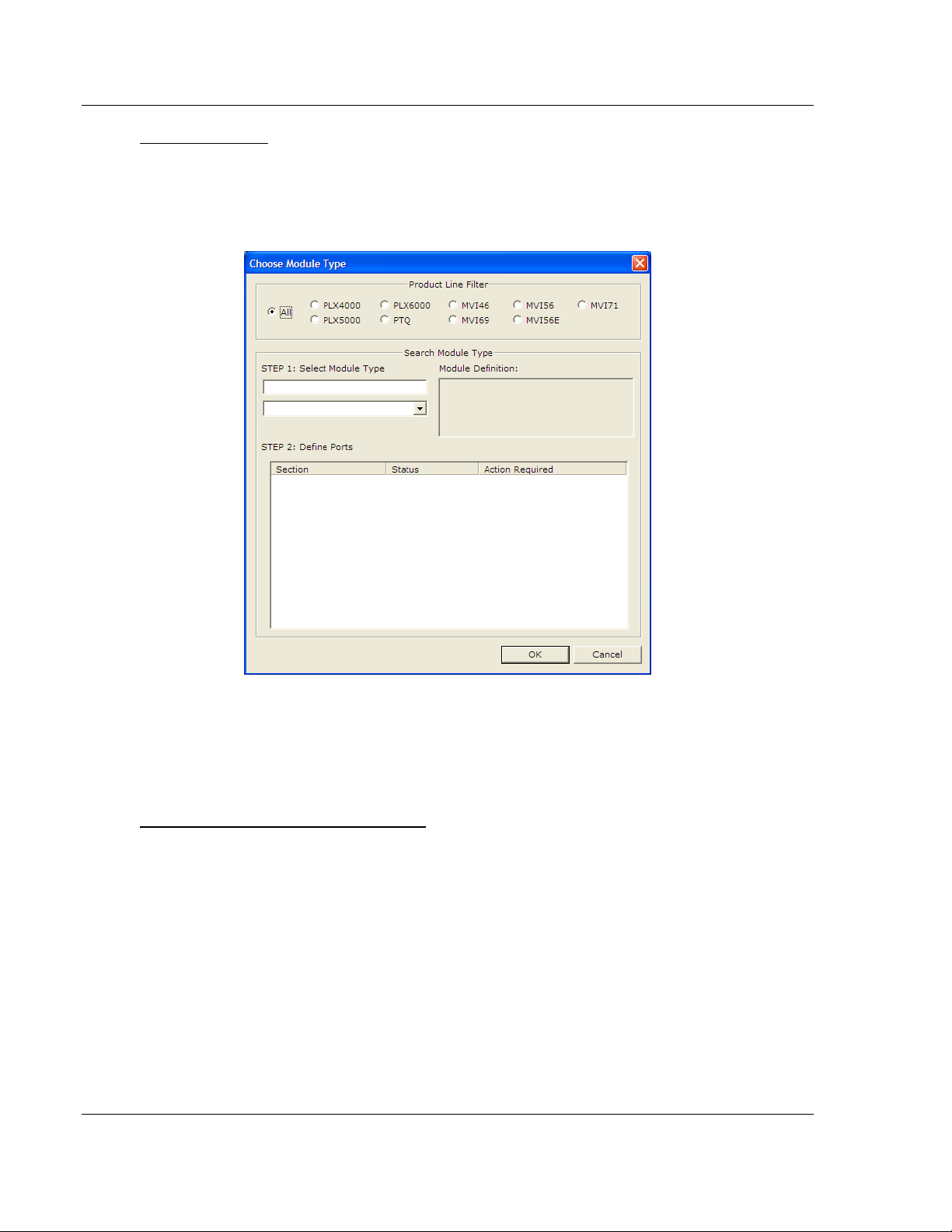
Adding a Module
Begin the process of creating your custom application configuration by selecting
the module type of your ProLinx gateway.
1 Double-click the D
EFAULT MODULE
icon to open the Choose Module Type
dialog box.
2 In the Choose Module Type dialog box, select the M
ODULE
type.
Or
1 Open the P
2 On the L
ROJECT
OCATION
menu and choose L
menu, choose A
DD MODULE
OCATION.
.
To add a module to a different location
1 Right-click the L
OCATION
folder and choose A
DD MODULE
. A new Module icon
appears.
Or
1 Select the L
2 From the P
OCATION
ROJECT
icon.
menu, select L
OCATION
, and then select A
DD MODULE
.
Page 20 of 157 ProSoft Technology, Inc.
March 23, 2011
Page 21
PDPMV1 ♦ ProLinx Gateway Configuration
PROFIBUS DPV1 Master Protocol Manual
Configuring Gateway Parameters
1 Click the [+] sign next to the module icon to expand gateway information.
2 Click the [+] sign next to any icon to view gateway information and
configuration options.
3 Double-click any icon to open an Edit dialog box.
4 To edit a parameter, select the parameter in the left pane and make your
changes in the right pane.
5 Click OK to save your changes.
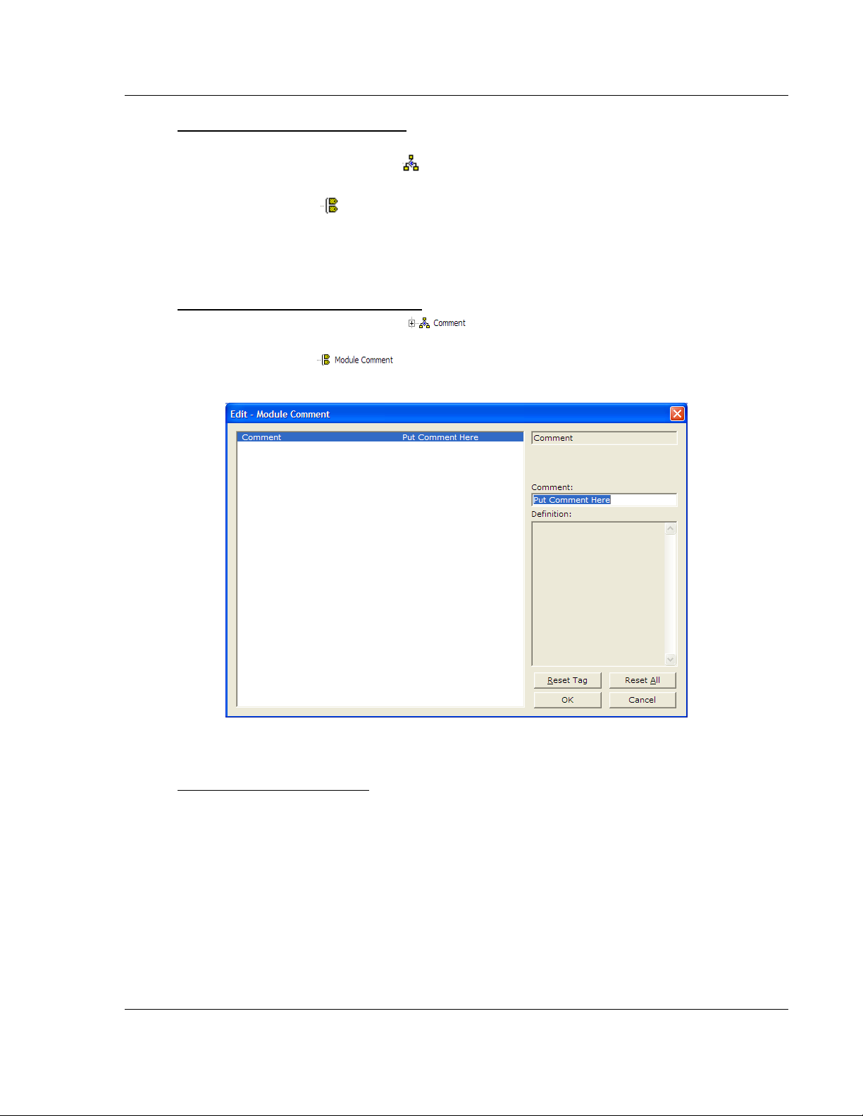
Creating Optional Comment Entries
1 Click the [+] to the left of the icon to expand the module
comments.
2 Double-click the icon. The Edit - Module Comment dialog box
appears.
3 Enter your comment and click OK to save your changes.
Printing a Configuration File
1 Select the module icon, and then click the right mouse button to open a
shortcut menu.
2 On the shortcut menu, choose V
IEW CONFIGURATION
. This action opens the
View Configuration window.
3 In the View Configuration window, open the F
ILE
menu, and choose P
RINT.
This action opens the Print dialog box.
4 In the Print dialog box, choose the printer to use from the drop-down list,
select printing options, and then click OK.
ProSoft Technology, Inc. Page 21 of 157
March 23, 2011
Page 22
Configuration PDPMV1 ♦ ProLinx Gateway
Protocol Manual PROFIBUS DPV1 Master
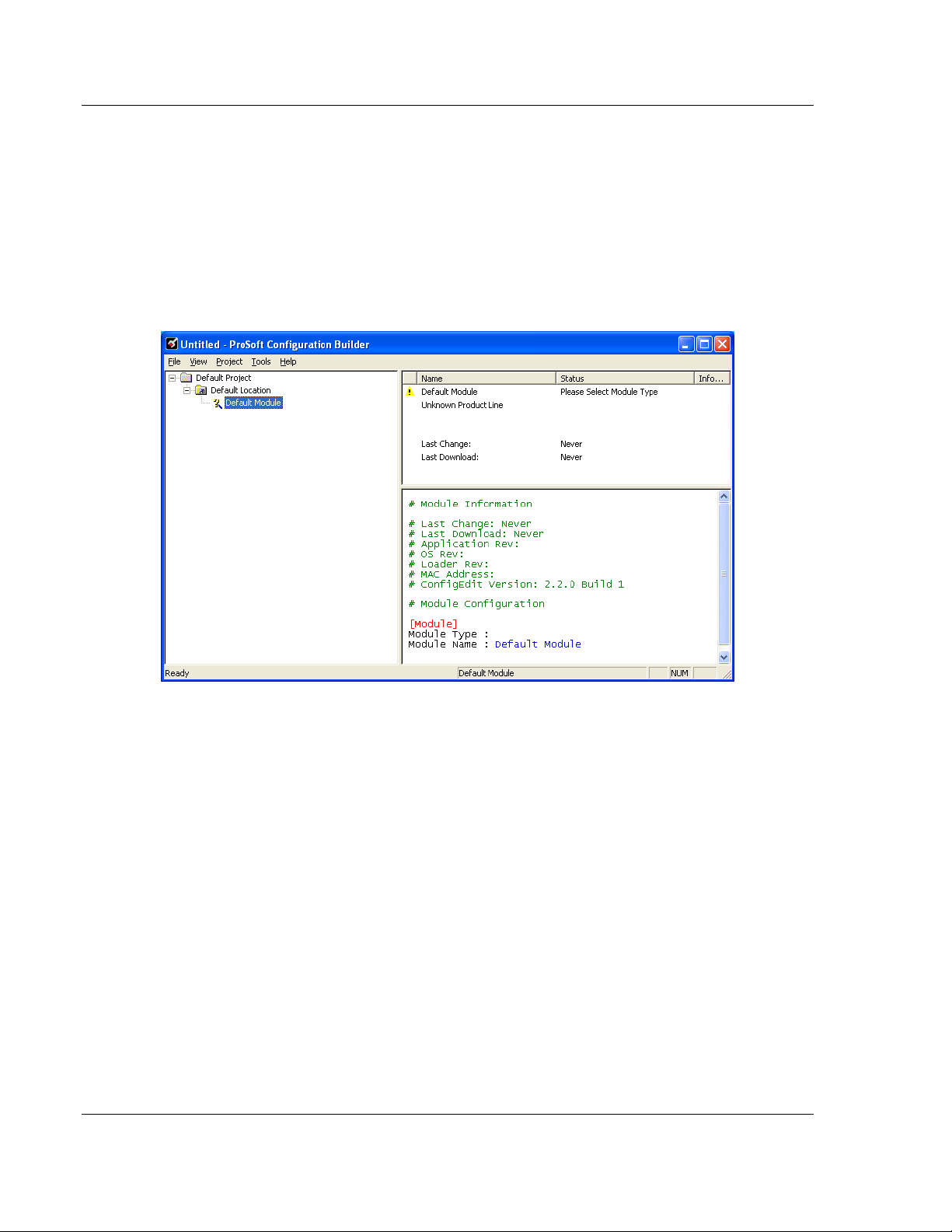
2.1.2 Setting Up the Project
To begin, start ProSoft Configuration Builder. If you have used other Windows
configuration tools before, you will find the screen layout familiar. ProSoft
Configuration Builder’s window consists of a tree view on the left, an information
pane and a configuration pane on the right side of the window. When you first
start ProSoft Configuration Builder, the tree view consists of folders for Default
Project and Default Location, with a Default Module in the Default Location
folder. The following illustration shows the ProSoft Configuration Builder window
with a new project.
Your first task is to add the PDPMV1 gateway to the project.
1 Use the mouse to select D
EFAULT MODULE
in the tree view, and then click the
right mouse button to open a shortcut menu.
Page 22 of 157 ProSoft Technology, Inc.
March 23, 2011
Page 23
PDPMV1 ♦ ProLinx Gateway Configuration
PROFIBUS DPV1 Master Protocol Manual
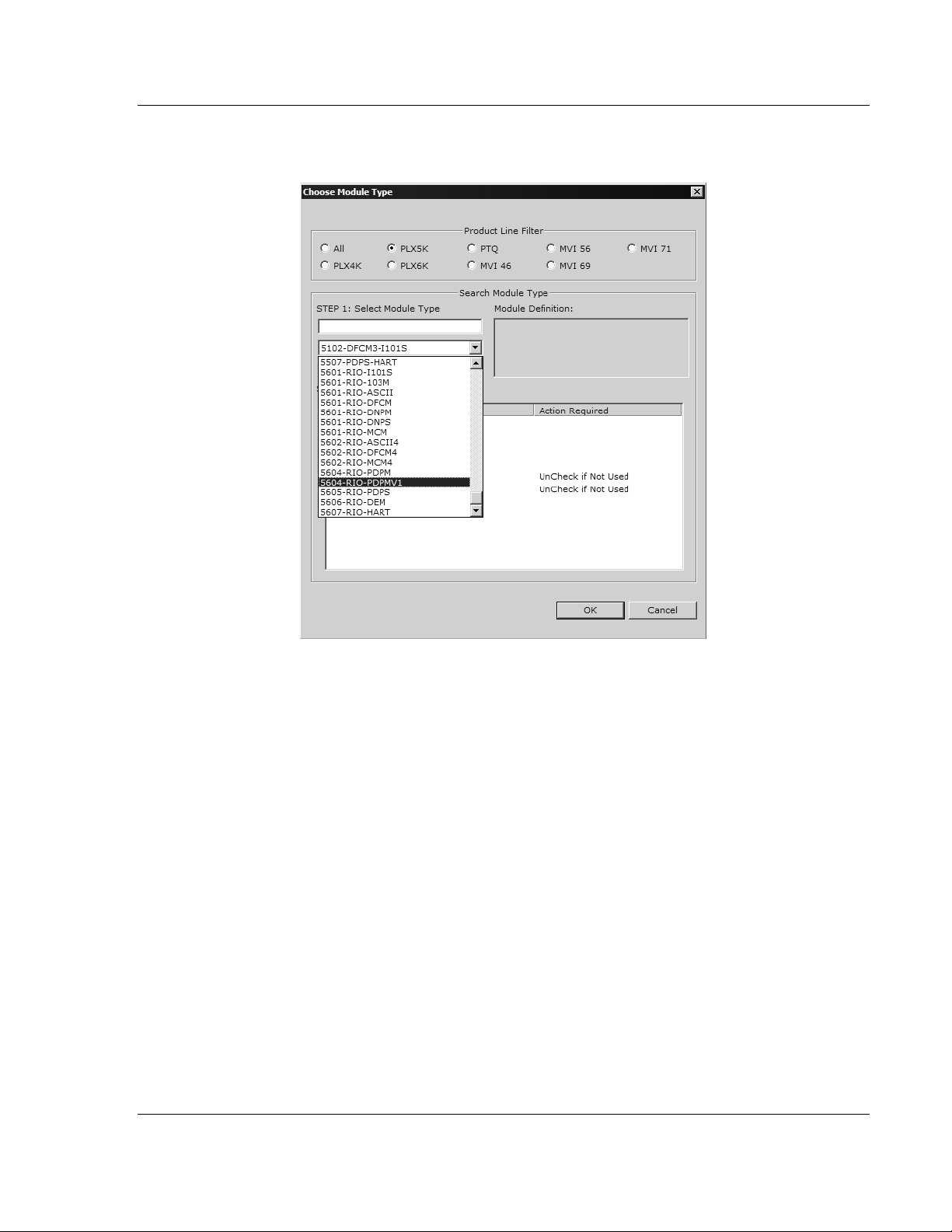
2 On the shortcut menu, select C
HOOSE MODULE TYPE
. This action opens the
Choose Module Type dialog box.
3 In the Product Line Filter area of the dialog box, select the gateway series
(PLX5K for wired gateways, or PLX6K for wireless gateways). In the Select
Module Type dropdown list, select the model number for your gateway (for
example, 5204-MNET-PDPMV1), and then click OK to save your settings and
return to the ProSoft Configuration Builder window.
The next task is to set the gateway parameters.
ProSoft Technology, Inc. Page 23 of 157
March 23, 2011
Page 24
Configuration PDPMV1 ♦ ProLinx Gateway
Protocol Manual PROFIBUS DPV1 Master
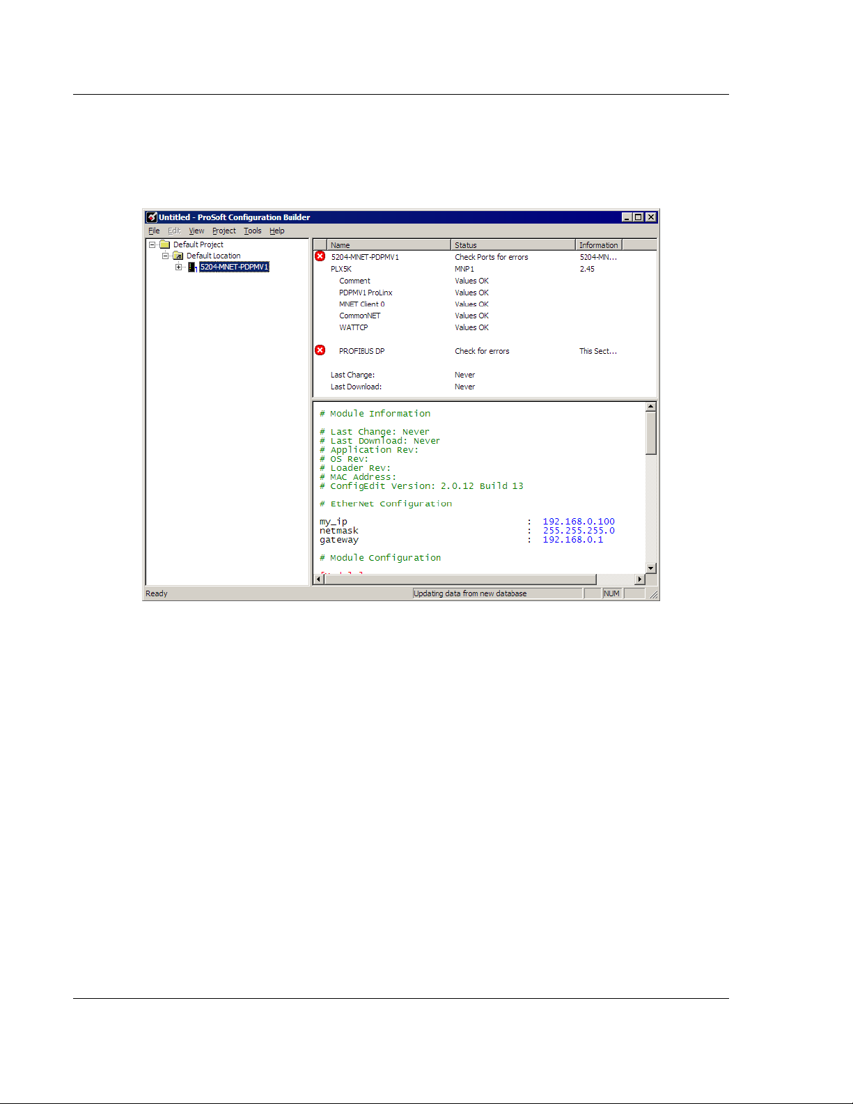
2.1.3 Setting Gateway Parameters
Notice that the contents of the information pane and the configuration pane
changed when you added the PDPMV1 gateway to the project. The red "X" icon
indicates that the gateway’s configuration is incomplete.
1 Click the plus sign [+] next to the module icon to expand the module tree, and
then expand the PLX PDPM-V1 tree.
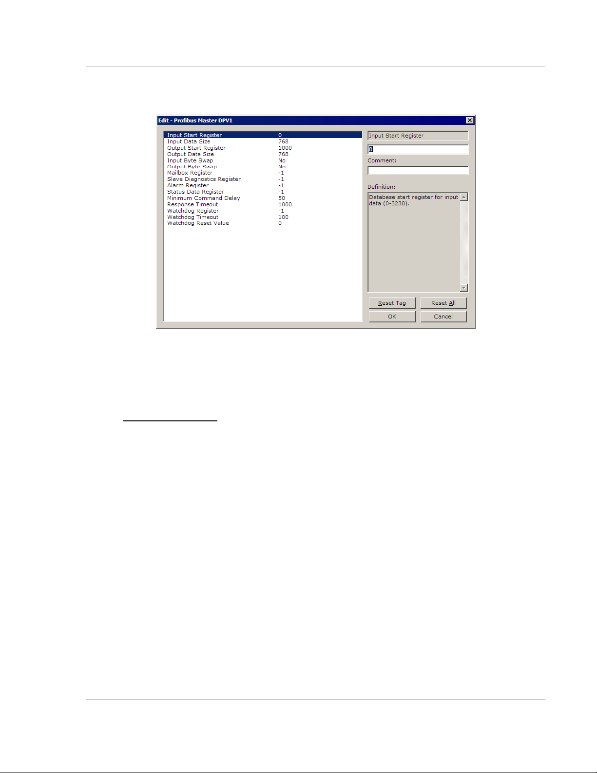
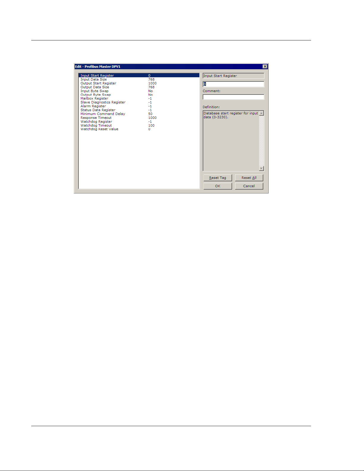
2 Double-click the PROFIBUS M
ASTER
DPV1 object. This action opens the Edit
dialog box.
3 In the Edit dialog box, enter the values for Input Data Size and Output Data
Size (PROFIBUS input and output point words) to match the values required
by your application. To change a value, select the parameter to modify in the
left pane, and then type the new value in the edit field in the right pane.
Page 24 of 157 ProSoft Technology, Inc.
March 23, 2011
Page 25
PDPMV1 ♦ ProLinx Gateway Configuration
PROFIBUS DPV1 Master Protocol Manual
For the sample application, the input and output data size values are fixed to
a value of 768.
4 Click OK to save your settings and return to the ProSoft Configuration Builder
window.
At this time, you may wish to rename the Default Project and Default Location
folders in the tree view.
To rename an object
1 Select the object, and then click the right mouse button to open a shortcut
menu. From the shortcut menu, choose R
ENAME
.
2 Type the name to assign to the object.
3 Click away from the object to save the new name.
ProSoft Technology, Inc. Page 25 of 157
March 23, 2011
Page 26
Configuration PDPMV1 ♦ ProLinx Gateway
Protocol Manual PROFIBUS DPV1 Master
2.2 PROFIBUS Master DPV1
2.2.1 Input Start Register
0 to 3230
Database start register for input data.
2.2.2 Input Data Size
0 to 768
Total number of PROFIBUS Input Words (one word equals two bytes) from all
PROFIBUS slaves. These Input Words will be the data received from slave
devices on the PROFIBUS network.
2.2.3 Output Start Register
0 to 3230
Database start register for output data.
2.2.4 Output Data Size
0 to 768
Total number of PROFIBUS Output Words (one word equals two bytes) to be
sent to all PROFIBUS slaves. These Output Words will be the data sent to slave
devices on the PROFIBUS network.
Page 26 of 157 ProSoft Technology, Inc.
March 23, 2011
Page 27

PDPMV1 ♦ ProLinx Gateway Configuration
PROFIBUS DPV1 Master Protocol Manual
2.2.5 Input Byte Swap
YES or NO
This parameter determines if the bytes in the PROFIBUS Input Data area are
swapped before being stored in the gateway memory database. If the parameter
is set to NO, no swapping will be applied. If the parameter is set to YES, the order
of bytes in each word will be swapped before being stored in memory.
Example:
With Input Byte Swap set to NO, incoming order is unchanged - ABCDEF
With Input Byte Swap set to YES, each byte pair is swapped - BADCFE
2.2.6 Output Byte Swap
YES or NO
This parameter determines if the bytes in the PROFIBUS Output Data area are
swapped before being transmitted to slaves on the PROFIBUS network. If the
parameter is set to NO, no swapping will be applied. If the parameter is set to
YES, the order of bytes in each word will be swapped before being transmitted.
Example:
With Output Byte Swap set to NO, outgoing output order is unchanged -
ABCDEF
With Output Byte Swap set to YES, each output byte pair is swapped -
BADCFE
ProSoft Technology, Inc. Page 27 of 157
March 23, 2011
Page 28

Configuration PDPMV1 ♦ ProLinx Gateway
Protocol Manual PROFIBUS DPV1 Master
2.2.7 Mailbox Register
0 to 3700, -1 to disable
Enter the database register for DPV1 mailbox messages, or -1 to disable mailbox
messages.
Mailbox messages can be sent through the database to the PROFIBUS Master.
This functionality requires 290 registers of the database. The map of the
database area utilized for this purpose is as follows.
Offset Description
0 This is the handshake word used to tell the PROFIBUS driver when a new acyclic
message is ready to send. If the value at this location is zero (0), no message will be
sent. If the value is not zero, then the PROFIBUS driver will send an acyclic
message using the contents of words 1 through 144. This handshake word should
be set to a non-zero value only after the complete acyclic message is stored in
offsets 1 to 144. After the PROFIBUS driver has added the acyclic message to the
queue, this register will be set to zero (0), so that the message is not repeated and to
indicate that a new acyclic message may be prepared.
NOTE: It would be a good practice to check the value of word 145 to be sure it is set
to zero (indicating that no acyclic messages are awaiting processing) before setting
this word to a non-zero value, triggering an acyclic message. This will help avoid
acyclic data collisions and data loss.
1 to 144 This area holds the acyclic message bytes to send. Please refer to Mailbox
Messaging (page 75) for the format of this data area.
NOTE: The header words (first 32 bytes) are stored in little-endian format and the
gateway will change the order to big-endian format before sending.
145 This handshake word indicates when a new acyclic response message has been
received by the PROFIBUS driver. If the value is zero (0), no response message has
been received. If the value is non-zero, a response message has been received and
stored in words 146 to 289. This data should be transferred by the other gateway
protocol for external processing. After the acyclic message has been externally
processed, a message should be returned through the other protocol that sets this
address to zero, to indicate readiness to receive and process a new acyclic response
message.
146 to 289 This area holds the acyclic message response bytes. Please refer to Mailbox
Messaging (page 75) for the format of this data area. The header words (first 32
bytes) are stored in little-endian format to make it easier to use.
Alarm acyclic messages are sent from the PROFIBUS driver to the database if
this feature is enabled by entering a valid database register in the configuration
file. This feature requires 145 database registers. The format of the data area is
as follows.
Offset Description
0 This is the alarm handshake word. If the value is not zero (0), alarm data is present
in the words 1 through 144. This register should be set to zero after the alarm is
process, so another alarm can be passed through the database. If this register is
zero (0), the database area is ready to receive a new alarm message.
1 to 144 This area holds the alarm acyclic message received by the PROFIBUS Master
device. Please refer to Mailbox Messaging (page 75) for a description of this acyclic
message. The header (first 32 bytes) of the message is stored in little-endian format
Page 28 of 157 ProSoft Technology, Inc.
March 23, 2011
to make it easier to process.
Page 29

PDPMV1 ♦ ProLinx Gateway Configuration
PROFIBUS DPV1 Master Protocol Manual
2.2.8 Slave Diagnostics Register
0 to 3600, -1 to disable
Enter the database register start location for DPV1 slave diagnostics messages,
or -1 to disable slave diagnostics.
When this register is enabled, the gateway will automatically place 378 words of
collected slave diagnostic data into the specified database start register.
Each slave requires 3 words of data. Data is gathered for slaves 0 to 125. The
application will poll for a new slave every 100 milliseconds.
2.2.9 Alarm Register
0 to 3900, -1 to disable
Enter the database register for DPV1 alarm messages, or -1 to disable alarm
messages.
2.2.10 Status Data Register
0 to 3900, -1 to disable
Enter the gateway memory database register for DP-V1 status data messages,
or -1 to disable status data messages.
2.2.11 Minimum Command Delay
0 to 32767
Minimum number of milliseconds between each command.
2.2.12 Response Timeout
0 to 5000 milliseconds
Number of milliseconds to wait for response to command. The value is set
depending upon the communication network used and the expected response
time of the slowest device on the network.
2.2.13 Watchdog Register
The Watchdog function allows the gateway to monitor a database register, the
Watchdog Register, to check for loss of communication with the non-PROFIBUS
communication protocol. If this function is used, the other gateway protocol is
expected to change the value in the Watchdog Register at an interval less than
the amount of time specified in the Watchdog Timeout parameter. If the value in
the Watchdog Register does not change within this amount of time, a
communication loss is assumed and the Watchdog function will set the
PROFIBUS outputs to the default value specified in the Watchdog Reset Value
parameter. To disable this function, set this parameter to a value of -1.
ProSoft Technology, Inc. Page 29 of 157
March 23, 2011
Page 30

Configuration PDPMV1 ♦ ProLinx Gateway
Protocol Manual PROFIBUS DPV1 Master
2.2.14 Watchdog Timeout
Sets the period of time (in 0.1s increments) for the gateway to wait for
communication loss detection. For example, set this parameter to 100 to set a
waiting period of 10 seconds. To disable this function, set this parameter to a
value of -1.
2.2.15 Watchdog Reset Value
Sets the value that will be sent to the PROFIBUS output byte registers upon
communication loss as detected by the Watchdog function. To disable this
function, set this parameter to a value of -1.
Page 30 of 157 ProSoft Technology, Inc.
March 23, 2011
Page 31

PDPMV1 ♦ ProLinx Gateway Configuration
PROFIBUS DPV1 Master Protocol Manual
2.3 PROFIBUS Master Commands
Type
Disabled: command will not be executed.
Enabled Continuous: command will be executed as frequently as set by Poll
Interval parameter.
Enabled Conditional: command will only be executed if the values at the
database at address set by Database Register parameter changes.
Enabled With Trigger: command will be executed if database trigger value
(set by Database Trigger parameter) is different from 0. After the command is
executed then the database trigger value is automatically set to 0 (zero).
Database Register
Database location for the operate mode if the count is set to 0 (zero).
Count
If Count is equal to zero, operate mode for command is derived from the
Database Register parameter in the gateway database. If the count is non-
zero, then the value in the Operation Mode field is used with the command.
Poll Interval
Sets how frequently in seconds the command will be executed if type is
configured as Enabled Continuous.
Swap
On requests used only for Function Code 33 (Acyclic Write).
On responses used for Function Code 4, 23, 24 and 32.
Database Trigger
This functionality requires the type parameter to be set as Enabled With
Trigger. The command will be executed if the database value set by this
parameter is non-zero. After the command is executed this value will be
automatically set to zero.
Function
Set Operate Mode (FC-2)
Set Slave Mode ( FC-3)
Get Slave Diagnostic Data (FC-4)
Get Slave Configuration (FC-5)
Start/Stop Slaves Dynamically (FC-11/FC-12)
Get Database Information (FC-23) (should be viewed in ASCII for CRC
Values)
Get Live List (FC-24)
Acyclic Read (FC-32)
Acyclic Write (FC-33)
ProSoft Technology, Inc. Page 31 of 157
March 23, 2011
Page 32

Configuration PDPMV1 ♦ ProLinx Gateway
Protocol Manual PROFIBUS DPV1 Master
Operation Mode
This field is required if the count field is set to 1 and represents the new
operation mode as follows:
o
64=Stop
o
128=Clear
o
192=Operate
Page 32 of 157 ProSoft Technology, Inc.
March 23, 2011
Page 33

PDPMV1 ♦ ProLinx Gateway Configuration
PROFIBUS DPV1 Master Protocol Manual
2.4 Example Mailbox Commands
The following examples show how to issue mailbox commands for Set Operating
Mode, Get Live List and Start/Stop Slaves. The rest of the supported mailbox
commands are configured the same way.
2.4.1 Set Operating Mode
1 In ProSoft Configuration Builder (PCB), expand the PLX PDPM-V1 section.
2 Select P
mouse button, and then choose C
ROFIBUS MASTER COMMANDS SET OPERATE MODE
ONFIGURE
, click the right
.
ProSoft Technology, Inc. Page 33 of 157
March 23, 2011
Page 34

Configuration PDPMV1 ♦ ProLinx Gateway
Protocol Manual PROFIBUS DPV1 Master
This action opens the Edit - Profibus Master Commands dialog box. This
dialog box allows you to add commands, one row at a time, with all the
necessary parameters.
3 To add a command, click A
DD ROW
. This action adds a command to the list,
populated with the default values for the command.
Page 34 of 157 ProSoft Technology, Inc.
March 23, 2011
Page 35

PDPMV1 ♦ ProLinx Gateway Configuration
PROFIBUS DPV1 Master Protocol Manual
4 To change the settings for the command, select the row, and then click E
DIT
ROW. This action opens the Edit - Row 1 dialog box.
Command Layout for Set Operating Mode
Column Value Description
Type 0 to 3
DB_Reg If the count is set to 0, this is the database location for the operate mode. Place a value of
Count If Count is equal to 0, operate mode for command is derived from the DB_Reg in the
Poll_Int Only if type = 1
Swap Not used
DB_Trigger This functionality requires the type parameter to be set as Enabled With Trigger. The
Func 2 Set Operate Mode.
Param_1 64, 128 or
192
0 Command Disabled
1 Command Enabled, use poll interval
2 Command executed when database changes (Func 2, 3, 11, 12 or 33 only)
3 Command executed when database trigger set Not equal to 0
64 or 128 or 192 in parameter 1 for description.
gateway database. If the count is not equal to 0, then the value in the Param_1 field is
used with the command.
command will be executed if the database value set by this parameter is nonzero. After
the command is executed this value will be automatically set to zero.
This field is required if the count field is set to 1 and represents the new operation mode
as follows: 64=Stop, 128=Clear and 192=Operate.
ProSoft Technology, Inc. Page 35 of 157
March 23, 2011
Page 36

Configuration PDPMV1 ♦ ProLinx Gateway
Protocol Manual PROFIBUS DPV1 Master
For this example, the command will stop the Master using database trigger
register 3200. Any nonzero value placed in this register will trigger the command
to execute. When the command has executed, the database register will be reset
to zero.
The following illustration shows the parameters that execute this command.
In the following illustration, from the Diagnostics window in ProSoft Configuration
Builder, the Master's operation state is Operate (C0 hex). To see this screen,
press [2] from the Main menu.
Page 36 of 157 ProSoft Technology, Inc.
March 23, 2011
Page 37

PDPMV1 ♦ ProLinx Gateway Configuration
PROFIBUS DPV1 Master Protocol Manual
When you download the configuration containing this mailbox command to the
gateway, and then return to the Diagnostics window, press [F] at the Main menu,
and then press [S] to view the command list. The following illustration shows the
command list. Notice that the first command matches the settings you made in
the Edit - Profibus Master Commands dialog box.
Press [M] to return to the Main menu, and then press [2] to view the Fieldbus
Data again. Notice that the Operation State has changed to Stop (40 hex).
ProSoft Technology, Inc. Page 37 of 157
March 23, 2011
Page 38

Configuration PDPMV1 ♦ ProLinx Gateway
Protocol Manual PROFIBUS DPV1 Master
2.4.2 Get Live List
1 In ProSoft Configuration Builder (PCB), expand the PLX PDPM-V1 section.
2 Select P
button, and then choose C
ROFIBUS MASTER COMMANDS GET LIVE LIST
ONFIGURE
.
, click the right mouse
This action opens the Edit - Profibus Master Commands dialog box. This
dialog box allows you to add commands, one row at a time, with all the
necessary parameters.
Page 38 of 157 ProSoft Technology, Inc.
March 23, 2011
Page 39

PDPMV1 ♦ ProLinx Gateway Configuration
PROFIBUS DPV1 Master Protocol Manual
3 To add a command, click A
DD ROW
. This action adds a command to the list,
populated with the default values for the command.
4 To change the settings for the command, select the row, and then click E
ROW. This action opens the Edit - Row 1 dialog box.
DIT
ProSoft Technology, Inc. Page 39 of 157
March 23, 2011
Page 40

Configuration PDPMV1 ♦ ProLinx Gateway
Protocol Manual PROFIBUS DPV1 Master
Command Layout for Get Live List
Column Value Description
Type 0, 1 or 3
DB_Reg Location where the results from the command are placed.
Count This parameter specifies the number of word registers in the reply to place in the
Poll_Int Only if type = 1
Swap Utilized on response message
DB_Trigger This functionality requires the type parameter to be set as Enabled With Trigger. The
Func 24 Get Live List
Type 0 Command Disabled
1 Command Enabled, use poll interval
3 Command executed when database trigger set != 0
database.
command will be executed if the database value set by this parameter is nonzero.
After the command is executed this value will be automatically set to zero.
For this example, the command will retrieve the list of Masters and slaves using
database trigger register 3201. Any nonzero value placed in this register will
trigger the command to execute. When the command has executed, the
database register will be reset to zero. Data from the response will be placed at
database address 3300, with a length of 128 words.
The following illustration shows the parameters that execute this command.
Page 40 of 157 ProSoft Technology, Inc.
March 23, 2011
Page 41

PDPMV1 ♦ ProLinx Gateway Configuration
PROFIBUS DPV1 Master Protocol Manual
When you download the configuration containing this mailbox command to the
gateway, and then return to the Diagnostics window, press [F] at the Main menu,
and then press [S] to view the command list. The following illustration shows the
command list. Notice that the first command matches the settings you made in
the Edit - Profibus Master Commands dialog box.
ProSoft Technology, Inc. Page 41 of 157
March 23, 2011
Page 42

Configuration PDPMV1 ♦ ProLinx Gateway
Protocol Manual PROFIBUS DPV1 Master
Any nonzero value placed in register 3201 issues mailbox command Get Live
List. The results of this command are placed in the database starting at register
3300.
A value of 03 HEX indicates this is the Master address which is in this case is
01.
A value of 04 HEX indicates the slave is not configured and not connected.
A value of 00 HEX means this slave is configured and connected. In this case
Slave #2 and Slave #6 are connected to the Master and are exchanging
cyclic data.
Page 42 of 157 ProSoft Technology, Inc.
March 23, 2011
Page 43

PDPMV1 ♦ ProLinx Gateway Configuration
PROFIBUS DPV1 Master Protocol Manual
2.4.3 Start/Stop Slaves
1 In ProSoft Configuration Builder (PCB), expand the PLX PDPM-V1 section.
2 Select P
mouse button, and then choose C
Profibus Master Commands dialog box. This dialog box allows you to add
commands, one row at a time, with all the necessary parameters.
ROFIBUS MASTER COMMANDS START/STOP SLAVE
ONFIGURE
. This action opens the Edit -
, click the right
ProSoft Technology, Inc. Page 43 of 157
March 23, 2011
Page 44

Configuration PDPMV1 ♦ ProLinx Gateway
Protocol Manual PROFIBUS DPV1 Master
3 To add a command, click A
DD ROW
. This action adds a command to the list,
populated with the default values for the command.
4 To change the settings for the command, select the row, and then click E
ROW. This action opens the Edit - Row 1 dialog box.
DIT
Page 44 of 157 ProSoft Technology, Inc.
March 23, 2011
Page 45

PDPMV1 ♦ ProLinx Gateway Configuration
PROFIBUS DPV1 Master Protocol Manual
Command Layout for Start/Stop Slaves
Column Value Description
Type 0 to 3
DB_Reg This is the database location where the 126 bytes of data for the message to be constructed
Count This field is not used as the message is always 63-words in length
Poll_Int Only if type = 1
Swap Utilized on request and response message
DB_Trigger Used if type is 3
Func 11
12
Param_1 This field contains the database address where the 63-words of response data from the
Type 0 Command Disabled
1 Command Enabled, use poll interval
2 Command executed when database changes
(Func 2, 3, 11, 12 or 33 only)
3 Command executed when database trigger set
Not equal to 0
for the mailbox command is present.
Start Slave(s)
Stop Slave(s)
mailbox is written. Set to -1, if the data is not to be written to the database.
For this example, the command will stop and start the specified slave(s) using
Database trigger register 3199 (stop) and 3198 (start). Any nonzero value placed
in either register will trigger the command to execute. When the command has
executed, the database register will be reset to zero. Data will be read from
database register 3200 for a count of 63 words. The response will be placed at
Database address 3500 with a length of 63 words.
The following illustration shows the parameters that execute this command.
ProSoft Technology, Inc. Page 45 of 157
March 23, 2011
Page 46

Configuration PDPMV1 ♦ ProLinx Gateway
Protocol Manual PROFIBUS DPV1 Master
When you download the configuration containing this mailbox command to the
gateway, and then return to the Diagnostics window, press [F] at the Main menu,
and then press [S] to view the command list. The following illustration shows the
command list. Notice that the first two commands match the settings you made in
the Edit - Profibus Master Commands dialog box.
When you place any value at database register 3199, this will issue the
command for the mailbox Stop slave(s). Slaves that are required to stop
communicating with the master will show RED. This is a byte map value entered
at database address 3200-3263. A decimal value of 257 in database register
3205 will stop slaves 10 and 11.
Page 46 of 157 ProSoft Technology, Inc.
March 23, 2011
Page 47

PDPMV1 ♦ ProLinx Gateway Configuration
PROFIBUS DPV1 Master Protocol Manual
The Monitor/Modify Slave screen in ProSoft Configuration Builder for PROFIBUS
will show that the slave is working properly.
Double-click on Slave 10.
ProSoft Technology, Inc. Page 47 of 157
March 23, 2011
Page 48

Configuration PDPMV1 ♦ ProLinx Gateway
Protocol Manual PROFIBUS DPV1 Master
The Diagnostic tab contains the following information for Slave 10, indicating that
the slave has stopped exchanging cyclic data.
To start the slaves again, place any value in database register 3198.
Important Note: Values in DB register are byte mapped values of 1 and 257. Use decimal values
only. There are 126 byte for 126 allowed PROFIBUS addresses. To stop slave address 100, place
a value of 1 in DB 50 of the 63. To stop slave address 10 and 11, place a value of 257 at Database
address 5 of the 63. If the Database start address is 3200, place a value of 257 at Database
address 3205.
Refer to Mailbox Message: Start Slave (page 95) and Mailbox Message: Stop Slave (page 96) for
more information on these commands.
DB_register and Param_1 should be same for both function codes 11 and 12. If you stop a certain
slave address, you must restart the same address.
Page 48 of 157 ProSoft Technology, Inc.
March 23, 2011
Page 49

PDPMV1 ♦ ProLinx Gateway Configuration
PROFIBUS DPV1 Master Protocol Manual
2.4.4 Other Mailbox Commands
3 - Set Slave Mode
Field Value Description
Type 0 to 3
DB_Reg Database location for the three values used by the
command.
Count If count == 0, the three values for the command are derived
from the database. If count != 0, the three parameters for the
command are present in the command list.
Poll_Int Only if type = 1
Swap Not used
DB_Trigger
Func 3
Param_1 0 to 125 or 127 This field represents the slave address for the command.
Address 127 is used for multicast address.
Param_2 Group Select Refer to Mailbox Message: Set Slave Mode (page 80)
Param_3 Control Command Refer to Mailbox Message: Set Slave Mode (page 80)
4 - Get Slave Diagnostic Data
Field Value Description
Type 0, 1 or 3
DB_Reg This is the database location where the results of the
command will be placed
Count This parameter specifies the number of words in the
response message to place in the database.
Poll_Int Only if type = 1
Swap Utilized on response message
DB_Trigger
Func 4
Param_1 0 to 125 This field represents the slave address for the command.
Param_2 Type of Req If 0, internal database used. If 1, data polled on network.
This last option is used if the slave is not controlled by this
Master.
ProSoft Technology, Inc. Page 49 of 157
March 23, 2011
Page 50

Configuration PDPMV1 ♦ ProLinx Gateway
Protocol Manual PROFIBUS DPV1 Master
5 - Get Slave Configuration
Field Value Description
Type 0, 1 or 3
DB_Reg This is the database location where the results of the
command will be placed
Count This parameter specifies the number of words in the
response message to place in the database.
Poll_Int Only if type = 1
Swap Utilized on response message
DB_Trigger
Func 5
Param_1 1 to 125 This field represents the slave address for the command.
23 - Get Database Information
Field Value Description
Type 0, 1 or 3
DB_Reg Location of the 4 words received in the response to this
request.
Count This field is not used as the message is always 4-words in
length
Poll_Int Only if type = 1
Swap Utilized on response message
DB_Trigger
Func 23
32 - Acyclic Read
Field Value Description
Type 0, 1 or 3
DB_Reg Database location where read data placed
Count Number of words in response message to write to the
database.
Poll_Int Only if type = 1
Swap Applied to data in response message
DB_Trigger
Func 32
Param_1 Slave Addr Slave address to read data from
Param_2 Slot Slot in slave to access
Param_3 Index Index in slave to access
Param_4 Len Length in bytes of data to be sent from the slave.
Page 50 of 157 ProSoft Technology, Inc.
March 23, 2011
Page 51

PDPMV1 ♦ ProLinx Gateway Configuration
PROFIBUS DPV1 Master Protocol Manual
33 - Acyclic Write
Field Value Description
Type 0 to 3
DB_Reg Starting database location of the write data.
Count Number of word registers to read from the database into the
command.
Poll_Int Only if type = 1
Swap Applied to data in request message
DB_Trigger
Func 33
Param_1 Slave Addr Slave address to write to with data
Param_2 Slot Slot in slave to access
Param_3 Index Index in slave to access
Param_4 Len Length in bytes of data to be sent to the slave.
ProSoft Technology, Inc. Page 51 of 157
March 23, 2011
Page 52

Configuration PDPMV1 ♦ ProLinx Gateway
Protocol Manual PROFIBUS DPV1 Master
2.5 Configuring the PROFIBUS DP Network
To configure your PROFIBUS DP network you must perform four tasks:
1 Install any PROFIBUS slave-specific device configuration files, typically
called .GSD files (page 52).
2 Configure the ProLinx PROFIBUS DP Master (page 52).
3 Configure the PROFIBUS slaves.
4 Print the Unity Passthru Memory Map.
2.5.1 Installing the GSD Files
ProSoft Configuration Builder (PCB) uses PROFIBUS slave device definition files
(GSD files) to obtain basic configuration information about the PROFIBUS slaves
you add to the network. The GSD configuration files identify the slave’s
capabilities so that the PDPMV1 can communicate with it correctly. Slave device
manufacturers provide the GSD files for the equipment they make. Slave device
files sometimes come in various languages. When a manufacturer provides slave
device files in several languages, it is a common practice to use the third letter of
the file extension to indicate the language used in the file. For instance:
o
.GSD is the most commonly used file extension and will usually be in
either English or German
o
.GSE will usually be in English
o
.GSS will usually be in Spanish
o
.GSF will usually be in French
o
other combinations may also be seen, as well as other languages using
the letters indicated above
Follow these steps to install the GSD file or files for your slave device or devices.
Tip: GSD configuration files for popular PROFIBUS slaves and ProSoft Technology solutions are
included with PCB. Before installing GSD files, browse the list of available slaves in the Tree View
window to see if GSD files for your slave are already installed.
GSD files are often both model number specific as well as model revision specific. Just because
you may have an older GSD file from a manufacturer for the particular make and model of your
slave device does not guarantee it will work for a newer revision of that device. Be sure you obtain
from the device manufacturer the correct GSD file or files for your PROFIBUS slave or slaves.
Page 52 of 157 ProSoft Technology, Inc.
March 23, 2011
Page 53

PDPMV1 ♦ ProLinx Gateway Configuration
PROFIBUS DPV1 Master Protocol Manual
To install GSD files manually
1 In ProSoft Configuration Builder tree view, click [+] to expand the module
tree, and then double-click the PROFIBUS DP icon. This action opens the
PDPMV1 PROFIBUS Master Setup dialog box.
2 Click the C
ONFIGURE
PROFIBUS button. This action opens the ProSoft
Configuration Builder for PROFIBUS application.
3 Open the T
OOLS
menu, and then choose I
NSTALL NEW
GS*
FILE
. This action
opens a dialog box that allows you to browse for the location of the GSD
configuration files to install. (Depending on the device and language used in
the file, the actual extension may be ".GSD", ".GSE", ".GSS", or other
combinations; hence the generic reference to ".GS*" files, where "*" is a
wildcard that stands for any letter.)
4 Choose the file to install, and then click O
PEN
. If the file already exists in the
configuration file path, you will be prompted to overwrite the file.
5 You will be prompted to associate the GSD configuration file with a bitmap
image of the slave device. Use the F
ILE / OPEN
dialog box to browse for the
location of the image file to use. If you have no device-specific bitmap file,
you may C
the Bus Configuration window for this slave device.
ANCEL
the bitmap upload, and a generic device icon will be used in
2.5.2 Configuring the PROFIBUS Slaves
There are two essential steps to configuring a slave:
1 Add the slave in ProSoft Configuration Builder (PCB) as a device connected
to the PROFIBUS Master, specifying the slave address and any necessary
input and output configuration. Download the PROFIBUS Master
configuration to the PDPMV1 module.
2 Configure the slave (using PCB or the configuration tool supplied by the
manufacturer, for some PROFIBUS slaves). Verify that the slave address
configured in the slave module matches the slave address configured in PCB.
Download the PROFIBUS Slave configuration to the slave module.
Scanning for Slaves Manually
Important: The GSD file for this example is not included on the ProLinx Solutions CD-ROM, and is
used for illustrative purposes only. You can download a variety of example GSD files from the
PROFIBUS Trade Organization website at www.profibus.org, or from the manufacturer's website
for your PROFIBUS slaves.
The following steps describe how to add and configure a Siemens EM 277 I/O
chassis to the PROFIBUS network. The configuration information (.GSD file) for
this device must be installed according to the procedure found in Install the GSD
Files (page 52). Most other PROFIBUS slaves can be configured in a similar
manner.
1 In ProSoft Configuration Builder for PROFIBUS, click the plus sign [+] to
expand the PROFIBUS DP tree.
ProSoft Technology, Inc. Page 53 of 157
March 23, 2011
Page 54

Configuration PDPMV1 ♦ ProLinx Gateway
Protocol Manual PROFIBUS DPV1 Master
2 Navigate to the folder containing the type of slave device to add
(PLCS/S
IEMENS
/EM 277, in this example), and then click the plus sign [+] to
expand the folder.
3 Click the EM 277 PROFIBUS-DP icon in the tree view and drag and drop the
icon into the Bus Configuration view. This action adds the slave device and
connects it to the Master in a network relationship.
Page 54 of 157 ProSoft Technology, Inc.
March 23, 2011
Page 55

PDPMV1 ♦ ProLinx Gateway Configuration
PROFIBUS DPV1 Master Protocol Manual
4 In the tree view, click the plus sign [+] to expand the slave device you added.
This action opens a list of device configuration values. The following
illustration shows the possible input/output configuration values for a Siemens
EM 277. The selections available for other devices may be different, so you
should review the specifications for the product you are installing in order to
determine the correct values to use.
5 Drag the input and output parameters to the slot location grid (Subscriber
List) below the Bus Configuration window. The slot view displays the slot
number, configuration data, and input and output addresses. The PROFIBUS
DP Master uses this information to identify and communicate with individual
slaves on the network.
ProSoft Technology, Inc. Page 55 of 157
March 23, 2011
Page 56

Configuration PDPMV1 ♦ ProLinx Gateway
Protocol Manual PROFIBUS DPV1 Master
For this example, we will configure 8 words of input and 32 words of output.
These input and output words are assigned to addresses within the
gateway's internal database.
For each new slave added to the PROFIBUS network, ProSoft Configuration
Builder automatically converts the input/output byte addresses to word
input/output addresses.
Tip: To make it easier to view the data from individual slaves, you can create a spreadsheet with
all added slaves and input and output data offsets, or you can view and print the data map.
Page 56 of 157 ProSoft Technology, Inc.
March 23, 2011
Page 57

PDPMV1 ♦ ProLinx Gateway Configuration
PROFIBUS DPV1 Master Protocol Manual
6 Double-click the S
LAVE
icon to view the Slave properties dialog box.
ProSoft Configuration Builder automatically assigns a PROFIBUS address to
each new slave. The slave address assignment begins at address 3 for the
first slave added to the network (addresses 0, 1, and 2 are reserved for use
with PROFIBUS Masters), and is incremented by 1 for each new slave added
to the network. You may, however, assign any address, 0-125 to any Master
or slave node as long as you do not assign the same address to more than
one device. You can change the address in the C
OMMON
tab of the Slave
properties dialog box. ProSoft Configuration Builder will not allow you to
assign a PROFIBUS address that is already in use by another device on this
network.
Leave the remaining settings unchanged for now, and click OK to close the
Slave properties dialog box.
7 Repeat steps 2 through 6 for all slaves you intend to place on the network.
8 When you are finished adding slaves, open the P
E
XIT.
Click Y
ES
to save the project and return to the PROFIBUS Master Setup
ROJECT
menu and choose
dialog box.
ProSoft Technology, Inc. Page 57 of 157
March 23, 2011
Page 58

Configuration PDPMV1 ♦ ProLinx Gateway
Protocol Manual PROFIBUS DPV1 Master
Using The Autoscan Feature
The concept of Automatic network scanning means that the user can instruct the
Bus Configuration window to automatically gather information about slaves that
are connected to the network. When the scan is completed the user can adopt
the detected slaves to the bus configuration and download to the Master.
This is a quick way to get a network up and running. However, one should be
aware that it is not guaranteed that any particular slave will enter data exchange
since the user parameter data might not match. This is especially obvious if no
associated GSD-file is found during the network scan, this means that no user
parameter data would be sent to the slave.
N
ETWORK SCAN
down menu for the M
is selectable from the Online menu as well as from the drop-
ASTER
icon.
Page 58 of 157 ProSoft Technology, Inc.
March 23, 2011
Page 59

PDPMV1 ♦ ProLinx Gateway Configuration
PROFIBUS DPV1 Master Protocol Manual
When the download is completed, the PROFIBUS Master Configuration window
will initialize the Master to operate as a Class 2 Master only. In this mode it is
possible to initialize the Master even if the database does not contain any slaves.
After successful initialization, the PROFIBUS Master Configuration window will
issue the following mailboxes in order to gather information about the connected
slaves:
1 1. Send FB_APPL_GET_LIVE_LIST in order to detect connected slaves,
2 2. Send FB_APPL_GET_SLAVE_DIAG (external request) to all devices
identified as slaves according to the Live list.
3 3. Send FB_APPL_GET_SLAVE_CONFIG to all devices identified as slaves
according to the Live list.
When the information is collected the PROFIBUS Master Configuration window
will find a matching GSD-file and extract information from it. Refer to the
flowchart below for this sequence:
ProSoft Technology, Inc. Page 59 of 157
March 23, 2011
Page 60

Configuration PDPMV1 ♦ ProLinx Gateway
Protocol Manual PROFIBUS DPV1 Master
GSD Selection Algorithm
If two or more matching GSD-files are found, the first one found should be
selected. The other compatible files should be stored so that the user can select
one of them instead. If the user selects another GSD-file, the PROFIBUS Master
Configuration window will run through the Module Selection Algorithm (described
below) again.
Module Selection Algorithm
The algorithm used to find modules in the GSD based on the Identifier byte(s) is
as follows:
Select the module that matches the largest number of Identifier bytes. If the GSD
contains two or more modules with the exact set of Identifier bytes, use the first
module found.
Example:
If a slave responds with identifier bytes: 0x11, 0x21, 0x31 and that the associated
GSD-file contains five modules: “A” = 0x11, “B” = 0x21, “C” = 0x31, “AB” = 0x11,
0x21 and “BC” = 0x21, 0x31. The PROFIBUS Master Configuration window will
then select modules "AB" and "C".
Note: If no matching module is found in the GSD, The PROFIBUS Master Configuration window
will display the identifier byte(s) instead.
Network scan window
The information extracted from the GSD-file(s) will be displayed in the Network
scan window.
Select
In this column all found slaves will be marked as selected by default, except for
slaves with the special address 126 (refer to the next section that describes the
Address column). Only selected slaves will be added to the PROFIBUS Master
Configuration when the A
DOPT SELECTED SLAVES
button is clicked.
Address
In this column the node address of the slaves will be displayed. Found slaves
should be listed in ascending order according to their node addresses.
Page 60 of 157 ProSoft Technology, Inc.
March 23, 2011
Page 61

PDPMV1 ♦ ProLinx Gateway Configuration
PROFIBUS DPV1 Master Protocol Manual
Special address 126 -Set Slave address:
If a slave with node address 126 is detected during the network scan, the
PROFIBUS Master Configuration window will display the address in red color. It
will not be possible for the user to adopt the slave to the configuration since it is
not allowed to exchange data with devices having this address. The check box in
the Select column will be grayed out.
To be able to adopt a slave with address 126 the user must first assign a valid
address by clicking the icon next to the node address. By doing so the Set Slave
Address dialog box is started.
Note that the Old slave address is preset to a value of 126 that is not editable (grayed out).
ProSoft Technology, Inc. Page 61 of 157
March 23, 2011
Page 62

Configuration PDPMV1 ♦ ProLinx Gateway
Protocol Manual PROFIBUS DPV1 Master
If the Slave is in the configuration already then it will not affect the addressing.
Example:
After scanning, the network finds these other slaves: 2, 6, 25, and 40
Slaves 2, 6, and 25 are found, but are marked as in the bus configuration (the
mapping of the inputs and outputs will not be affected)
Slaves 40 is new and could be added and the input/output addressing will be
appended to the end as shown on the last screen.
Page 62 of 157 ProSoft Technology, Inc.
March 23, 2011
Page 63

PDPMV1 ♦ ProLinx Gateway Configuration
PROFIBUS DPV1 Master Protocol Manual
The PROFIBUS Master Configuration window will prevent the user from selecting
a New slave address that is already occupied by another device; this includes
detected Master stations as well. If the user selects an occupied address, a
message similar to the one shown here will open.
When an address has been successfully assigned, the PROFIBUS Master
Configuration window will update the Network scan window as shown here. The
node address will be updated to the one that the user selected in the Set Slave
dialog box. The check box in the Select column will be marked allowing the user
to adopt the slave to the configuration.
Slave
In this column the name of the slave as stated in the assigned GSD-file will be
displayed. If no matching GSD-file is found the Ident number will be displayed in
red color in the drop-down list.
Module
This column shows the name of the module(s) as stated in the assigned GSDfile, which matches the Identifier byte(s) derived from the GetCfg mailbox
message. If no GSD-file or no matching module is found the Identifier byte(s) will
be displayed in red color. If the configuration for a slave is constructed of several
modules, the modules will be listed under each other.
ProSoft Technology, Inc. Page 63 of 157
March 23, 2011
Page 64

Configuration PDPMV1 ♦ ProLinx Gateway
Protocol Manual PROFIBUS DPV1 Master
If there is more than one module in the GSD-file that matches the Identifer bytes,
the first matching module will be displayed in blue color in a drop-down list. The
drop-down list will contain all other matching modules so that the user can select
the desired one.
Note: Only modules that have the exact same Identifer bytes as the first matching module will be
displayed in the drop-down list.
GSD-file
This column shows the name of the GSD-file that matches the Ident number
derived from the SlaveDiag mailbox message. If there are more files with the
same Ident number in the device catalog, the first matching GSD-file will be
displayed in blue color in a drop-down list.
This could be the case if the device catalog contains two or more brand labeled
devices, or GSD-files for two or more languages (for example NICEDEV.GSD
and NICEDEV.GSE) exist.
Note: If the user selects another GSD-file, The PROFIBUS Master Configuration window will
update the modules for that slave accordingly.
Page 64 of 157 ProSoft Technology, Inc.
March 23, 2011
Page 65

PDPMV1 ♦ ProLinx Gateway Configuration
PROFIBUS DPV1 Master Protocol Manual
If no GSD-file is found the user will be able to copy the expected GSD to the
device catalog by clicking the icon next to the text No GSD found. This will start
the Install new GS*-file dialog box. When the file is installed, the PROFIBUS
Master Configuration window will verify that the installed file matches the slave
and update the modules for the slave accordingly.
Rescan
Pressing the Y
ES
button will trigger a new network scan. Before proceeding with
the scan a message similar to the one below will appear. If a new scan is
accepted, detected slaves found during the previous scan will be lost.
Adopt selected slaves
Pressing this button will cause all selected slaves to be adopted to the
PROFIBUS Master Configuration window. Before carrying on with this action a
message similar to the one below will appear.
ProSoft Technology, Inc. Page 65 of 157
March 23, 2011
Page 66

Configuration PDPMV1 ♦ ProLinx Gateway
Protocol Manual PROFIBUS DPV1 Master
If accepted, the network scan window will close and the PROFIBUS Master
Configuration window will be populated with the slaves that were found during
the network scan.
Note: Slave: is equal to the Ident number and that the Device path: and Order number/designation
fields are left empty.
Cancel and Help
If the C
ANCEL
button is pressed a message similar to the one below will appear.
If the H
ELP
button is pressed the online help will start.
Page 66 of 157 ProSoft Technology, Inc.
March 23, 2011
Page 67

PDPMV1 ♦ ProLinx Gateway Configuration
PROFIBUS DPV1 Master Protocol Manual
Set_Param (SAP61)
ProSoft PROFIBUS slave (PDPS) devices have a configurable parameter for
SPC3 User Prm Byte. The following illustration shows the value of this parameter
in ProSoft Configuration Builder for PROFIBUS, the configuration tool for ProSoft
PROFIBUS Master devices.
ProSoft Technology, Inc. Page 67 of 157
March 23, 2011
Page 68

Configuration PDPMV1 ♦ ProLinx Gateway
Protocol Manual PROFIBUS DPV1 Master
Parameter Data Structure
SPC3 evaluates the first seven data bytes (without user prm data), or the first
eight data bytes (with user prm data). The first seven bytes are specified
according to the standard. The eighth byte is used for SPC3-specific
communications. The additional bytes are available to the application.
Byte Bit Position Designation
7 6 5 4 3 2 1 0
0 Lock
Reg
1
2
3
4
5
6
7
8 to 243
Unio
Req
Sync
Req
Free
Req
WD on Res Res Res Station status
WD_Fact_1
WD_Fact_2
MinTSDR
Ident_Number_High
Ident_Number_Low
Group_Ident
Spec_User_Prm_Byte
User_Prm_Data
Byte 7 Spec_User_Prm_Byte
Bit Name Significance Default State
0 Dis_Startbit The start bit monitoring in the receiver
is switched off with this bit
1 Dis_Stopbit Stop bit monitoring in the receiver is
switched off with this bit
2 WD_Base This bit specifies the time base used to
clock the watchdog.
WD_Base = 0: time base 10 ms
WD_Base = 1: time base 1 ms
3 to 4 Res To be parameterized with 0 0
5 Publisher_Enable DXB-publisher-functionality of the
SPC3 is activated with this bit
6 to 7 Res To be parameterized with 0 0
Dis_Startbit = 1,
Start bit monitoring is switched off.
Dis_Stopbit = 0
Stop bit monitoring is not switched off.
WD_Base = 0
The time base is 10 ms.
Publisher_Enable = 0, DXB-requesttelegrams are ignored;
Publisher_Enable = 1, DXB-requesttelegrams are processed
Page 68 of 157 ProSoft Technology, Inc.
March 23, 2011
Page 69

PDPMV1 ♦ ProLinx Gateway Configuration
PROFIBUS DPV1 Master Protocol Manual
2.5.3 Printing the ProLinx Memory Map
The ProLinx Memory Map dialog box uses the information about your
PROFIBUS Master and slaves to display the data types that are configured. You
need this information to know the starting address of cyclic I/O and gateway
status data.
ProSoft Technology, Inc. Page 69 of 157
March 23, 2011
Page 70

Configuration PDPMV1 ♦ ProLinx Gateway
Protocol Manual PROFIBUS DPV1 Master
To view or print the ProLinx Memory Map
1 In the Master Setup dialog box, click the S
HOW
PLX M
EMORY MAP
button,
near the bottom of the window. This action opens ProLinx Memory Map
window.
2 Notice that there are buttons in the Display area of the dialog box to show
inputs and outputs. These input and output maps correspond to the input and
output data you configured for the PROFIBUS slaves (page 53). Notice also
that there are check boxes to display slot numbers and PROFIBUS
addresses.
3 Click P
RINT
to print the input and output maps for reference. Note that you
must do this for both input and output maps.
4 When you have finished printing the ProLinx memory maps, click OK to close
the dialog box. Click OK again to close the Master Setup dialog box.
5 Keep the printed memory maps available so you can refer to them when you
configure the sample ladder logic in RSLogix. The sample ladder logic
contains input and output arrays that must be cross-referenced with the
variables.
The next step is to download the project to the ProLinx gateway.
Page 70 of 157 ProSoft Technology, Inc.
March 23, 2011
Page 71

PDPMV1 ♦ ProLinx Gateway Configuration
PROFIBUS DPV1 Master Protocol Manual
2.6 Downloading the Project to the Gateway
In order for the gateway to use the PROFIBUS network settings you configured,
you must download (copy) the updated Project file from your PC to the gateway.
To download the project file
1 In the tree view in ProSoft Configuration Builder, click once to select the
gateway that has PLX PDPMV1 section.
2 Open the P
program will scan your PC for a valid com port (this may take a few seconds).
When PCB has found a valid com port, the following dialog box will open.
ROJECT
menu, and then choose M
ODULE
> D
OWNLOAD
. The
3 Choose the com port to use from the dropdown list, and then click the
D
OWNLOAD
button.
The gateway will perform a platform check to read and load its new settings.
When the platform check is complete, the status bar in ProSoft Configuration
Builder will be updated with the message Module Running.
ProSoft Technology, Inc. Page 71 of 157
March 23, 2011
Page 72

Configuration PDPMV1 ♦ ProLinx Gateway
Protocol Manual PROFIBUS DPV1 Master
2.7 Backing Up the Project
In this step, you will create a backup copy of your project and configuration files.
The backup procedure saves your data for reuse on another machine, or allows
you to restore your data in the event of a system failure.
To save your project and configuration files
1 In ProSoft Configuration Builder tree view, click [+] to expand the PDPMV1
tree, and then double-click the PROFIBUS DP icon. This action opens the
PDPMV1 PROFIBUS Master Setup dialog box.
2 In the PDPMV1 PROFIBUS Master Setup dialog box, click the E
M
ASTER CONFIG
button. This action saves the PROFIBUS network
configuration for your gateway in an XML file. The recommended location for
this file is your My Documents folder.
Tip: You can use the XML file created by ProSoft Configuration Builder in this step to simplify the
task of configuring additional PROFIBUS network modules. Because it saves the entire network
configuration, you can add modules quickly by modifying only the items that are unique for each
device, typically the slot number and I/O addresses. To use this saved configuration, open
Windows Explorer, navigate to the folder where you saved the Master Configuration XML file, and
then drag the file onto the new PROFIBUS DP icon in the ProSoft Configuration Builder tree view.
XPORT
3 In ProSoft Configuration Builder, open the F
ILE
menu, and then choose S
AVE
AS.
4 Name the project file, and click S
AVE
. The recommended location for this file
is your My Documents folder.
Note: All PCB project files and module-related files are automatically saved to C:\PCBExportfFiles.
A complete backup consists of the Project and Master Configuration files, plus
the GSD configuration files. The default location for the GSD files is
C:\Documents and Settings\All Users\Application Data\ProSoft\GSD (Windows
XP / 2000) or C:\My Documents\.
Page 72 of 157 ProSoft Technology, Inc.
March 23, 2011
Page 73

PDPMV1 ♦ ProLinx Gateway Configuration
PROFIBUS DPV1 Master Protocol Manual
PCB does this complete backup for you automatically. The default location for
these backup files is C:\PCBExportFiles. All the files associated with your PCB
configuration will be stored in a folder with the same name as the name you used
to save your PCB configuration (.ppf) file. When you exit PCB, you will be
prompted to overwrite your Export folder files.
If you have made changes to your configuration settings, you should click the
Y
ES
button every time you see this dialog box to have the backup files updated.
Having all the files for your PCB configuration stored in one folder makes it easier
to transfer the application from one system to the other or to send your files to
ProSoft Technical Support when you need assistance.
ProSoft Technology, Inc. Page 73 of 157
March 23, 2011
Page 74

Configuration PDPMV1 ♦ ProLinx Gateway
Protocol Manual PROFIBUS DPV1 Master
Page 74 of 157 ProSoft Technology, Inc.
March 23, 2011
Page 75

PDPMV1 ♦ ProLinx Gateway Mailbox Messaging
PROFIBUS DPV1 Master Protocol Manual
3 Mailbox Messaging
In This Chapter
Mailbox Message Queuing .................................................................... 76
Special Function Mailbox Messaging Commands ................................. 77
Mailbox Messaging Error Codes ........................................................... 99
The PDPMV1 PROFIBUS DP Master uses a process called Mailbox Messaging
to exchange parameter data between the processor, Master, and slave devices.
This process provides a way to encapsulate and prioritize commands and data
sent between the PROFIBUS Master and slaves.
The PROFIBUS DP-V1 protocol specifies two types of data transmission
messages (telegrams): Cyclic Data Telegrams and Acyclic Data Telegrams.
Cyclic data communication is the exchange of normal slave input and output (I/O)
data and is handled automatically by the Master in a defined, recurring,
deterministic sequence based on the configuration you create in ProSoft
Configuration Builder (PCB).
Acyclic communication extends data communication beyond normal I/O data to
allow moving field device parameterization and calibration data over the bus
during runtime and to allow for extended diagnostics and alarm messages.
Acyclic data telegrams are transmitted in the gaps between cyclic data telegrams
and, therefore, have a lower priority and get less bandwidth than cyclic data.
Mailbox Messaging commands are incorporated into the sample ladder logic.
Mailbox messages and responses to mailbox messages are stored in mailbox
data types.
The following chapter discusses these features in more detail.
ProSoft Technology, Inc. Page 75 of 157
March 23, 2011
Page 76

Mailbox Messaging PDPMV1 ♦ ProLinx Gateway
Protocol Manual PROFIBUS DPV1 Master
3.1 Mailbox Message Queuing
The PDPMV1 gateway operates asynchronously on the Mailbox Messages and
as such provides for the queuing of the messages as they are received. The
queue sizes used in the gateway are as follows:
Queue Type Queue Size Max Description
Output Message from processor 20 Number of messages that the ProLinx
Input Messages for processor 20
Alarm Messages from slaves for
processor
20
3.1.1 Queue Timeouts
The PDPMV1 gateway will only allow a message to stay in a queue for up to 10
seconds. If the PROFIBUS Master (for output messages) or the processor (for
input and alarm messages) has not successfully received a message within 10
seconds, the gateway will clear the message out of the queue.
gateway will queue by type of message. Note
that status of the queues can be monitored
via the Queue Message Count values.
Page 76 of 157 ProSoft Technology, Inc.
March 23, 2011
Page 77

PDPMV1 ♦ ProLinx Gateway Mailbox Messaging
PROFIBUS DPV1 Master Protocol Manual
3.2 Special Function Mailbox Messaging Commands
The PDPMV1 gateway supports some extended PROFIBUS functions, using a
mailbox data exchange mechanism implemented in the gateway.
The PDPMV1 gateway supports the following special functions through this
mailbox messaging scheme.
Important Note: When you use the database to send your mailbox command, the application
places a value of B0 into the first byte of the Message ID word. This value identifies the mailbox
command issued, and differentiates the source of the message: either the database or the
command structure. You should use a message ID value between 1 and 255 in the message ID
header.
Initiated from ProSoft Configuration Builder
Message Description
Set Operation Mode Controls the operating state of the PROFIBUS Master
Set Slave Mode Sends special control command to one or several slaves
(Sync/Freeze)
Get Slave Diag Gest diagnostic information from a slave
Get Slave Config Gets slave configuration
Get Database Information
Get Live List Gets information from all nodes on the network
MSAC1 Read DPV1 acyclic read (Class 1)
MSAC1 Write DPV1 acyclic write (Class 1)
Start Slave Start Slaves Dynamically
Stop Slave Stop Slaves Dynamically
DPV1 Alarm Handling: Generated by Slave Devices
Message Description
Alarm Indications Spontaneous alarm indication from DPV1 slave. Structure of
data is slave-dependent
Alarm Confirmation This message is sent by the ProLinx gateway automatically as a
confirmation to the alarm indications.
The provided Function Blocks simplify the processor logic required to implement
these messaging mailbox exchanges.
Sending a mailbox message to the PDPMV1 gateway is a relatively simple
process, however, it is important to follow a certain sequence.
ProSoft Technology, Inc. Page 77 of 157
March 23, 2011
Page 78

Mailbox Messaging PDPMV1 ♦ ProLinx Gateway
Protocol Manual PROFIBUS DPV1 Master
Mailbox Message Structure: To PDPMV1 Gateway
Byte Offset Type Description
0 Message ID Processor logic or user set. The Message ID field is used
by the ProLinx gateway to detect a new message in the
PROFIBUS Output data image.
When a non-zero value is detected, the message is
processed immediately. The sample ladder logic assigns
specific message IDs to different mailbox messages.
1 Message Info See individual commands for data values to be entered in
2 Command
3 Data Size
4 Frame Count
5 Frame Number
6 Offset High
7 Offset Low
8 Extended Word 1
9 Extended Word 2
10 Extended Word 3
11 Extended Word 4
12 Extended Word 5
13 Extended Word 6
14 Extended Word 7
15 Extended Word 8
- See individual
149
commands
each of these register locations
3.2.1 Mailbox Message: Set Operating Mode
This command allows setting the operating mode of the PROFIBUS Master
(STOP, CLEAR, or OPERATE).
Parameter Description
Command Initiator Application
Command Name SET OPERATING MODE
Command Number 0200h
Fragmented No
Extended Header Data Fault information may be returned in the header of the response.
Page 78 of 157 ProSoft Technology, Inc.
March 23, 2011
Page 79

PDPMV1 ♦ ProLinx Gateway Mailbox Messaging
PROFIBUS DPV1 Master Protocol Manual
Command and Response Layout: Set Operating Mode
Message ID
Acyclic Message Status
Command
Data size
Frame count
Frame number
Offset high
Offset low
Extended word 1 Mode Conf. Req
Extended word 2
Extended word 3
Extended word 4
Extended word 5
Extended word 6
Extended word 7
Extended word 8
Command
Word
(ID)
4002h
0002h
0000h
0001h
0001h
0000h
0000h
-
-
-
-
-
-
-
Response
Appl. Specific Error Code
(ID)
0002h
0002h Set Operation Mode
0000h
0001h
0001h
0000h
0000h
Mode Conf. Req
-
-
-
-
-
Fault Information
Mode
40h: STOP
80h: CLEAR
C0h: OPERATE
Conf. Req.
00h: Confirmation is not required
01h: Confirmation required. All confirmations are automatically sent by the
Master; the user is not required to send a confirmation message.
Fault Information
If "Invalid Other" is returned in the Acyclic Message Status Word in the header of
the response, information about the fault can be found here. Refer to Return
Codes (page 100) for more information.
0100h: Invalid operating mode
FF00h: Module not initialized
ProSoft Technology, Inc. Page 79 of 157
March 23, 2011
Page 80

Mailbox Messaging PDPMV1 ♦ ProLinx Gateway
Protocol Manual PROFIBUS DPV1 Master
3.2.2 Mailbox Message: Set Slave Mode
In addition to station-related user data transfer, which is executed automatically,
the Master can send control commands to a single slave, a group of slaves, or all
slaves simultaneously. These control commands are transmitted as multicast
commands. This permits use of sync and freeze modes for event-controlled
synchronization of the slaves.
The slaves begin sync mode when they receive a sync command from their
assigned Master. The outputs of all addressed slaves are then frozen in their
current state. During subsequent user data transmissions, the output data are
stored on the slaves, but the output states remain unchanged. The stored output
data are not sent to the outputs until the next sync command is received. Sync
mode is concluded with the unsync command.
Similarly, a freeze control command causes the addressed slaves to assume
freeze mode. In this operating mode, the states of the inputs are frozen until the
Master sends the next freeze command. Freeze mode is concluded with the
unfreeze command.
Note 1: It is only possible to send control commands when operating mode is either CLEAR or
OPERATE.
Note 2: Not all slaves support this feature. Refer to the documentation for the actual slave for more
information.
Parameter Description
Command Initiator Application
Command Name SET SLAVE MODE
Command Number 0300h
Fragmented No
Extended Header Data Fault information may be returned in the header of the response.
Page 80 of 157 ProSoft Technology, Inc.
March 23, 2011
Page 81

PDPMV1 ♦ ProLinx Gateway Mailbox Messaging
PROFIBUS DPV1 Master Protocol Manual
Command and Response Layout: Set Slave Mode
Message ID
Acyclic Message Status
Command
Data size
Frame count
Frame number
Offset high
Offset low
Extended word 1 Slave
Extended word 2 Control
Extended word 3
Extended word 4
Extended word 5
Extended word 6
Extended word 7
Extended word 8
Command
(ID)
4002h
Word
0003h
0000h
0001h
0001h
0000h
0000h
Group Select
Address
Command
-
-
-
-
-
Response
Slave
Address
Control
Command
Extended Fault Information
(ID)
0002h
0003h Set Slave Mode
0000h
0001h
0001h
0000h
0000h
Group Select
-
-
-
-
Fault Information
Acyclic Message Status Word
Refer to Acyclic Message Status Word (page 99).
Slave Address
Range 1 to 125; 127
If the request applies for only one slave, that Slave Address must be entered in
the range 1 to 125. If a slave group is to be addressed, Slave Address should be
127 (Multicast address).
ProSoft Technology, Inc. Page 81 of 157
March 23, 2011
Page 82

Mailbox Messaging PDPMV1 ♦ ProLinx Gateway
Protocol Manual PROFIBUS DPV1 Master
Group Select
Range 01h to FFh (Bit Coded)
This parameter determines which group to address. Refer to the following
example:
b7 b6 b5 b4 b3 b2 b1 b0
Group 8 Group 7 Group 6 Group 5 Group 4 Group 3 Group 2 Group 1
Example: To address Group 1, 2, and 4, the Group Select value should be D0h.
If an individual slave should be addressed, the correct group selection must also
be made, because the slave will ignore the message if it does not belong to the
requested group(s).
What group(s) a slave belongs to is determined during network configuration,
and is downloaded during initialization to each slave via the PROFIBUS telegram
"Set_Prm".
Control Command
This parameter specifies the command to send:
Bit Explanation
0 (LSB) Reserved, set to zero
1 Reserved, set to zero
2 Unfreeze input data
3 Freeze input data
4 Unsynchronize output data
5 Synchronize output data
6 Reserved, set to zero
7 (MSB) Reserved, set to zero
Combinations of the bits (Unsync/Sync and Unfreeze/Freeze)
Bits 0 or 6 Bits 1 or 7 Explanation
0 0 No Function
0 1 Function will be activated
1 0 Function will be inactive
1 1 Function will be inactive
Page 82 of 157 ProSoft Technology, Inc.
March 23, 2011
Page 83

PDPMV1 ♦ ProLinx Gateway Mailbox Messaging
PROFIBUS DPV1 Master Protocol Manual
Fault Information and Extended Fault Information
"Fault Information" Contents "Extended Fault Information" Contents
0100h Address out of range -
0200h Group number 0 not
permitted
0A00h Failed to send Global
Control request
FE00h Command not
possible in Class 2
only mode
FF00h Module not initialized -
-
0A00h Incorrect operation mode (Clear/Operate Only)
0150h Invalid Freeze Group (Group is not initiated to be
Freeze Group)
0250h Invalid Sync Group (Group is not initiated to be
Sync Group)
0350h Incorrect Control Command
0450h No Sync -/ or Freeze groups enabled in Master
configuration
-
3.2.3 Mailbox Message: Get Slave Diagnostics
This command reads diagnostic data from a specified slave.
Note: The response data size depends on the actual slave implementation. Range 6 to 244.
Parameter Description
Command Initiator Application
Command Name GET SLAVE DIAGNOSTICS
Command Number 0400h
Fragmented No
Extended Header Data Fault information may be returned in the header of the response.
ProSoft Technology, Inc. Page 83 of 157
March 23, 2011
Page 84

Mailbox Messaging PDPMV1 ♦ ProLinx Gateway
Protocol Manual PROFIBUS DPV1 Master
Command and Response Layout: Get Slave Diagnostics
Message ID
Acyclic Message Status
Command
Data size
Frame count
Frame number
Offset high
Offset low
Extended word 1 Slave
Extended word 2
Extended word 3
Extended word 4
Extended word 5
Word
Command
Address
(ID)
4002h
0004h
0000h
0001h
0001h
0000h
0000h
Type of
Request
-
-
-
-
Response
Address
Error Code 1 Error Code 2
(ID)
0002h
0004h Get Slave Diagnostics
(Size of data)
0001h
0001h
0000h
0000h
Slave
Type of
Request
-
-
-
Extended word 6
Extended word 7
Extended word 8
-
-
-
Error Code 3 Error Code 4
Extended Fault Info
Fault Information
Station
Status 1
Station
Status 3
Ident Number Response data word 3
Extended Diagnostic Data Response data word 4
Station
Status 2
Station
Status 4
Response data word 1
Response data word 2
...
...
Response data word n
Acyclic Message Status Word
Refer to Acyclic Message Status Word (page 99).
Slave Address
Range 1 to 125; specifies the slave from which to read diagnostics.
Page 84 of 157 ProSoft Technology, Inc.
March 23, 2011
Page 85

PDPMV1 ♦ ProLinx Gateway Mailbox Messaging
PROFIBUS DPV1 Master Protocol Manual
Type of request
00h: Internal slave diagnostic request. Returns the diagnostic information stored
in the Master. Can only be requested for slaves configured by the Master.
Note: Not allowed when operating in "Class 2-Only" mode.
01h: External slave diagnostic request. Sends a diagnostic request on the
network to the specified slave. Can be requested for all slaves on the network.
Error code [1 ...4]
If "Return Code" equals 8030h ("Negative indication from lower layer"), status
values according to the DP-specification may be available in "Error Code 1".
Error Codes 2 to 4 are reserved.
Refer to Mailbox Messaging Error Codes (page 99).
Return Code
Refer to Mailbox Messaging Error Codes (page 99)
Fault Information
If "Invalid Other" is returned in the Acyclic Message Status Word in the header of
the response, information about the fault can be found here.
0100h: Address out of range.
0200h: Incorrect "Type of request"
0A00h: Failed to read diagnostic data from slave. Refer to Return Codes (page
100) for additional fault information.
0B00h: Remote station failure. Refer to Return Codes (page 100) for additional
fault information.
FE00h: Command not possible; module operates as a Class 2 Master only.
FF00h: Module offline (not initialized or no valid database).
Station Status [1 ... 3]
Refer to EN50170 Vol. 2 for more information.
Master Address
Address of the Master that parameterized the slave.
Ident Number
Unique ID assigned by the PROFIBUS User Organization.
Extended Diagnostic Data
Slave user-specific data. Refer to the documentation for the actual slave for more
information.
ProSoft Technology, Inc. Page 85 of 157
March 23, 2011
Page 86

Mailbox Messaging PDPMV1 ♦ ProLinx Gateway
Protocol Manual PROFIBUS DPV1 Master
3.2.4 Mailbox Message: Get Slave Configuration
This command reads the actual configuration (identifier bytes) of a specified
slave.
Note: The response data size depends on the actual slave implementation. Range 6 to 244.
Parameter Description
Command Initiator Application
Command Name GET SLAVE CONFIGURATION
Command Number 0500h
Fragmented No
Extended Header Data Fault information may be returned in the header of the response.
Command and Response Layout: Get Slave Configuration
Message ID
Acyclic Message Status
Command
Data size
Frame count
Frame number
Offset high
Offset low
Extended word 1 Slave
Extended word 2
Extended word 3
Extended word 4
Extended word 5
Extended word 6
Extended word 7
Extended word 8
Command Response
Word
Address
(ID)
4002h
0005h
0000h
0001h
0001h
0000h
0000h
-
-
-
-
-
-
-
Slave
Address
Error Code 1 Error Code 2
Error Code 3 Error Code 4
(ID)
0002h
0005h Get Slave Configuration
(Size of data) Number of identifier bytes
0001h
0001h
0000h
0000h
Return Code
Fault Information
Identifier byte 1 Response data word 1
Identifier byte 2 Response data word 2
Identifier byte 3 Response data word 3
... ...
Identifier byte n Response data word n
(n)
-
-
-
Page 86 of 157 ProSoft Technology, Inc.
March 23, 2011
Page 87

PDPMV1 ♦ ProLinx Gateway Mailbox Messaging
PROFIBUS DPV1 Master Protocol Manual
Acyclic Message Status Word
Refer to Acyclic Message Status Word (page 99).
Slave Address
Range 1 to 125; specifies the slave from which to read the configuration.
Error Code [1 … 4]
If "Return Code" equals 3080h ("Negative indication from lower layer"), status
values according to the DP-specification may be available in "Error Code 1",
Error Codes 2 through 3 are reserved. Refer to Mailbox Messaging Error Codes
(page 99).
Return Code
Refer to Mailbox Messaging Error Codes (page 99).
Fault Information
If "Invalid other" is returned in the Acyclic Message Status Word in the header of
the response, information about the fault can be found here. Refer to Acyclic
Message Status Word (page 99).
0100h: Address out of range.
0A00h: Failed to execute request. Refer to Return Codes (page 100) for
additional information.
0B00h: Remote station failure. Refer to Return Codes (page 100) for additional
information.
FF00h: Module not initialized.
Identifier Bytes [1 … n]
Refer to EN50170 Vol. 2 for information on the structure of these bytes. In
addition, refer to the documentation provided with the slave device for more
information.
3.2.5 Mailbox Message: Get Database Information
This command fetches information about the stored database (that is, userspecific data that was downloaded to the gateway in the Message Data 1 to 32
via mailbox "FB_APPL_END_DATABASE_DOWNLOAD" or from the
configuration tool).
This message also returns information about the amount of allocated I/O-data in
the input and output areas. These sizes can be used by the application to set up
the I/O-lengths for the ANYBUS_INIT message.
Parameter Description
Command initiator Application
Command Name FB_APPL_GET_DATABASE_INFO
Command number 0017h
Fragmented No
Firmware Revision All
ProSoft Technology, Inc. Page 87 of 157
March 23, 2011
Page 88

Mailbox Messaging PDPMV1 ♦ ProLinx Gateway
Protocol Manual PROFIBUS DPV1 Master
Command and Response Layout: Get Database Information
Message ID (ID) (ID)
Acyclic Message Status
Word
Command 0017h 0017h Get Database Info
Data size 0000h 0040h
Frame count 0001h 0001h
Frame number 0001h
Offset high 0000h
Offset low 0000h 0000h
Extended word 1
Extended word 2 -
Extended word 3 - Init Output Size
Extended word 4 -
Command
4002h 0002h
Response
Number of identifier bytes
0001h
0000h
Total Output Length
Total Input Length
Init Input Size
(n)
Extended word 5 -
Extended word 6 -
Extended word 7 -
Extended word 8 - Fault Information
No. of
Slaves
Database Description
(ASCII, 64 characters)
-
-
-
Response data word 1 to 32
Page 88 of 157 ProSoft Technology, Inc.
March 23, 2011
Page 89

PDPMV1 ♦ ProLinx Gateway Mailbox Messaging
PROFIBUS DPV1 Master Protocol Manual
Total Input Length, Total Output Length: The sum of Input/Output lengths for
all slaves in the database (in bytes).
Init Input size, Init Output size: Required initialization Input/Output sizes for the
current database. If the slaves are located in a contiguous block these sizes are
the same as total Input/Output lengths.
Note: The input/output direction refers to the directions and naming used for the DPRAM areas,
not to the input/output directions used in the bus database or the The Bus Configuration windowPB.
Database Description: String of ASCII characters that describes the data base
file. This is the string that was written to the database by the
"FB_APPL_END_DATABASE_DOWNLOAD" command.
No. of Slaves: Number of configured slaves in the database.
Fault Information
If "Invalid Other" is returned in the Acyclic Message Status Word in the header of
the response, information about the fault can be found here. Refer to Return
Codes (page 100) for more information.
0001h: No database in flash, or download in progress.
3.2.6 Mailbox Message: Get Live List
This command returns 127 bytes of information about the nodes on the network.
Every byte stands for one bus subscriber, and the position of the byte in the
response data assigns the address (0 to 126); the content assigns the Station
Type.
This command can be sent in all operation modes (STOP, CLEAR, and
OPERATE); however, the module must be initialized properly.
Parameter Description
Command Initiator Application
Command Name GET LIVE LIST
Command Number 1800h
Fragmented No
Extended Header Data Fault information may be returned in the header of the response.
ProSoft Technology, Inc. Page 89 of 157
March 23, 2011
Page 90

Mailbox Messaging PDPMV1 ♦ ProLinx Gateway
Protocol Manual PROFIBUS DPV1 Master
Command and Response Layout: Get Live List
Message ID
Acyclic Message Status
Command
Data size
Frame count
Frame number
Offset high
Offset low
Extended word 1
Extended word 2
Extended word 3
Extended word 4
Extended word 5
Extended word 6
Extended word 7
Extended word 8
Message Data byte 1
Message Data byte 2
Message Data byte 3
Message Data byte "n"
Command Response
Word
(ID)
4002h
0018h
0000h
0001h
0001h
0000h
0000h
-
-
-
-
-
-
-
-
...
(ID)
0002h
0018h Get Live List
007Fh 127 Bytes of Data
0001h
0001h
0000h
0000h
Return Code
Fault Information
Station Type 0 Response Data Byte 1
Station Type 1 Response Data Byte 1
Station Type 2 Response Data Byte 1
... Response Data Byte 1
Station Type 126 Response Data Byte 1
-
-
-
-
-
-
Acyclic Message Status Word
Refer to Acyclic Message Status Word (page 99).
Station Type [0 … 126]
00h: Slave Station
01h: Master Station not yet ready for Token ring (station only physically at the
bus)
02h: Master Station ready to enter Token ring (there is not yet any Token
transmission)
03h: Master Station in Token Ring (Token transmission through the station)
04h: Station does not exist
Fault Information
If "Invalid Other" is returned in the Acyclic Message Status Word in the header of
the response, information about the fault can be found here. Refer to Acyclic
Message Status Word (page 99).
0AH00: Failed to build Live List.
FF00h: Module offline (not initialized or no valid database)
Page 90 of 157 ProSoft Technology, Inc.
March 23, 2011
Page 91

PDPMV1 ♦ ProLinx Gateway Mailbox Messaging
PROFIBUS DPV1 Master Protocol Manual
3.2.7 Mailbox Message: Acyclic Data Read: Class 1
This command initiates a DPV1 Class 1 acyclic read request. Refer to EN50170
(DPV1) for more information.
Parameter Description
Command Initiator Application
Command Name MSAC1 READ
Command Number 2000h
Fragmented No
Extended Header Data Fault information may be returned in the header of the response.
Command and Response Layout: Acyclic Read
Message ID
Acyclic Message Status
Command
Data size
Frame count
Frame number
Offset high
Offset low
Extended word 1 Slave Addr. Slot Number Slave Addr. Slot Number
Extended word 2 Index Length Index Length
Extended word 3
Extended word 4
Extended word 5
Extended word 6
Extended word 7
Extended word 8
Command Response
Word
(ID)
4002h
0020h
0000h
0001h
0001h
0000h
0000h
-
-
-
-
-
-
Error Code 1 Error Code 2
Extended Fault information
(ID)
0002h
0020h Acyclic Read
(Size of data) Number of data bytes (n)
0001h
0001h
0000h
0000h
Error
Fault Information
Data 1 Response Data byte 1
Data 2 Response Data byte 1
Data 3 Response Data byte 1
... ...
Data n Response Data byte 1
-
-
Decode
Acyclic Message Status Word
Refer to Acyclic Message Status Word (page 99).
ProSoft Technology, Inc. Page 91 of 157
March 23, 2011
Page 92

Mailbox Messaging PDPMV1 ♦ ProLinx Gateway
Protocol Manual PROFIBUS DPV1 Master
Slave Address
Station address of the slave responder.
Slot Number and Slot Index
Used in the slave to address the desired data block.
Length
This parameter specifies the number of bytes of the data block to read. If the
server data block length is less than requested, the length of the response will be
the actual length of the data block. If the server data block is greater or equal, the
response will contain the same amount of data.
The slave may answer with an error response if data access is not allowed.
Data [1 … n]
Returned data.
Fault Information and Extended Fault Information
If "Invalid Other" is returned in the Acyclic Message Status Word in the header of
the response, information about the fault can be found here.
"Fault Information" "Extended Fault Information" Contents
0100h Address out of range -
0A00h Failed to execute request Refer to Return Codes (page 100).
0B00h Remote station failure
1000h Remote station DPV1 failure Function_Number
1100h Length out of range (>240 bytes) -
1200h Slave does not support DPV1 -
1300h Slave not active or not present in
configuration
FE00h Command not possible in "Class 2-
Only" mode
FF00h Module offline (not initialized or no
valid database)
-
-
-
Error Decode, Error Code 1 and Error Code 2
If "Fault Information" contains error code 1000h, more information according to
the DPV1 specification can be found here.
Page 92 of 157 ProSoft Technology, Inc.
March 23, 2011
Page 93

PDPMV1 ♦ ProLinx Gateway Mailbox Messaging
PROFIBUS DPV1 Master Protocol Manual
3.2.8 Mailbox Message: Acyclic Data Write: Class 1
This command initiates a DPV1 Class 1 acyclic write request. Refer to EN50170
(DPV1) for more information.
Parameter Description
Command Initiator Application
Command Name MSAC1 WRITE
Command Number 2100h
Fragmented No
Extended Header Data Fault information may be returned in the header of the response.
Command and Response Layout: Acyclic Write
Message ID
Acyclic Message Status
Command
Data size
Frame count
Frame number
Offset high
Offset low
Extended word 1 Slave Addr. Slot Number Slave Addr. Slot Number
Extended word 2 Index Length Index Length
Extended word 3
Extended word 4
Extended word 5
Extended word 6
Extended word 7
Extended word 8
Message Data byte 1
Message Data byte 2
Message Data byte 3
Message Data byte n
Command Response
Word
(ID)
4002h
0021h
(Size of data)
0001h
0001h
0000h
0000h
-
-
-
-
-
Data 1
Data 2
Data 3
...
...
Data n
Error Code 1 Error Code 2
Extended Fault information
(ID)
0002h
0021h Acyclic Write
(Size of data) Number of data bytes (n)
0001h
0001h
0000h
0000h
-
-
Error
Fault Information
Data 1
Data 2
Data 3
...
Data n
Decode-
Acyclic Message Status Word
Refer to Acyclic Message Status Word (page 99).
ProSoft Technology, Inc. Page 93 of 157
March 23, 2011
Page 94

Mailbox Messaging PDPMV1 ♦ ProLinx Gateway
Protocol Manual PROFIBUS DPV1 Master
Slave Address
Station address of the slave responder.
Slot Number and Slot Index
Used in the slave to address the desired data block.
Length
This parameter specifies the number of bytes to write. If the destination data
block size is less than requested, the response will contain an error message. If
the data block length is greater than or equal to the requested length, the
response contains the number of bytes that have been written. The slave may
answer with an error response if data access is not allowed.
Data [1 … n]
Data that should be written.
Fault Information and Extended Fault Information
If "Invalid Other" is returned in the Acyclic Message Status Word in the header of
the response, information about the fault can be found here:
"Fault Information" "Extended Fault Information" Contents
0100h Address out of range -
0A00h Failed to execute request Refer to Return Codes (page 100).
0B00h Remote station failure
1000h Remote station DPV1 failure Function_Number
1100h Length out of range (>240 bytes) -
1200h Slave does not support DPV1 -
1300h Slave not active or not present in
configuration
FE00h Command not possible in "Class 2-
Only" mode
FF00h Module offline (not initialized or no
valid database)
-
-
-
Error Decode, Error Code 1, and Error Code 2
If "Fault Information" contains error code 1000h, more information according to
the DPV1 specification can be found here.
Page 94 of 157 ProSoft Technology, Inc.
March 23, 2011
Page 95

PDPMV1 ♦ ProLinx Gateway Mailbox Messaging
PROFIBUS DPV1 Master Protocol Manual
3.2.9 Mailbox Message: Start Slave
This mailbox message starts a selection of slaves that was previously removed
from the processing cycle by means of the mailbox message
FB_APPL_STOP_SLAVE.
This message is allowed in all operation modes (STOP, CLEAR and OPERATE).
Note: The message will be accepted even if one or several slaves are not part of the configuration
and can therefore obviously not be started. The application can, however, find out about this
situation by evaluating the "Fault information" and "Message data words" of the response.
Command and Response Layout: Start Slave
Message ID
Acyclic Message Status
Command
Data size
Frame count
Frame number
Offset high
Offset low
Extended word 1
Extended word 2
Extended word 3
Extended word 4
Extended word 5
Extended word 6
Extended word 7
Extended word 8
Message data word 1 Slave 0 Slave 1 Slave 0 Slave 1
Message data word 2 Slave 2 Slave 3 Slave 2 Slave 3
Message data word 3 to
Message data word 63 Slave 124 Slave 125 Slave 124 Slave 125
Command:
Message data word 1-63
Byte-array stating which slave/slaves to start. Array index is equal to slave
address.
0: Do not affect slave
1: Start slave
2-255: Reserved
Command Response
Word
62
(ID)
4002h
000Bh
007Eh
0001h
0001h
0000h
0000h
-
-
-
-
-
-
-
... ... ... ...
Additional Fault Information
(ID)
0002h
000Bh Start Slave
007Eh
0001h
0001h
0000h
0000h
-
-
-
-
-
Fault Information
ProSoft Technology, Inc. Page 95 of 157
March 23, 2011
Page 96

Mailbox Messaging PDPMV1 ♦ ProLinx Gateway
Protocol Manual PROFIBUS DPV1 Master
Response:
Acyclic Message Status Word (in response header)
"Invalid Data Size" is returned if Data size in the command header does not
equal 126.
If "Invalid Other" is returned, further information is to be found in Extended
word 8.
Additional Fault information (Extended word 7)
If Extended word 8 equals 0x000A -"Failed to execute request" additional info
can be found here
Fault information (Extended word 8)
0x0001: Invalid setting in Message data word 1-63 of the command.
0x0002: At least one slave reports a warning. Refer to Message data word 1-
63.
0x000A: Failed to execute request. Additional fault information is to be found
in Extended word 7.
0x00FE: Command not possible, module operates as Class 2 Master only.
0x00FF: Module not initialized (this command is only possible after
END_INIT).
Message data word 1-63
Byte-array stating the status of the slaves. Array index is equal to slave
address.
0: Slave unaffected
1: Slave started
2: Warning - Slave could not be started because it is not part of the
configuration
3.2.10 Mailbox Message: Stop Slave
This mailbox message stops a selection of slaves from the processing cycle.
This message is allowed in all operation modes (STOP, CLEAR and OPERATE).
Note: The message will be accepted even if one or several slaves are not part of the configuration
and can therefore obviously not be stopped. The application can, however, find out about this
situation by evaluating the "Fault information" and "Message data words" of the response.
Page 96 of 157 ProSoft Technology, Inc.
March 23, 2011
Page 97

PDPMV1 ♦ ProLinx Gateway Mailbox Messaging
PROFIBUS DPV1 Master Protocol Manual
Command and Response Layout: Stop Slave
Message ID
Acyclic Message Status
Command
Data size
Frame count
Frame number
Offset high
Offset low
Extended word 1
Extended word 2
Extended word 3
Extended word 4
Extended word 5
Extended word 6
Extended word 7
Extended word 8
Message data word 1 Slave 0 Slave 1
Command
(ID)
4002h
Word
000Ch
007Eh
0001h
0001h
0000h
0000h
-
-
-
-
-
-
-
-
Response
Additional Fault Information
Slave 0 Slave 1
(ID)
0002h
000Ch Stop Slave
007Eh
0001h
0001h
0000h
0000h
-
-
-
-
-
-
Fault Information
Message data word 2 Slave 2 Slave 3
Message data word 3 to
62
Message data word 63 Slave 124 Slave 125
... ...
Slave 2 Slave 3
... ...
Slave 124 Slave 125
Command:
Message data word 1-63
Byte-array stating which slave/slaves to stop. Array index is equal to slave
address.
0: Do not affect slave
1: Stop slave
2-255: Reserved
ProSoft Technology, Inc. Page 97 of 157
March 23, 2011
Page 98

Mailbox Messaging PDPMV1 ♦ ProLinx Gateway
Protocol Manual PROFIBUS DPV1 Master
Response:
Acyclic Message Status Word (in response header)
"Invalid Data Size" is returned if Data size in the command header does not
equal 126.
If "Invalid Other" is returned, further information is to be found in Extended
word 8.
Additional Fault information (Extended word 7)
If Extended word 8 equals 0x000A -"Failed to execute request" additional info
can be found here.
Fault information (Extended word 8)
0x0001: Invalid setting in Message data word 1-63 of the command.
0x0002: At least one slave reports a warning. Refer to Message data word 1-
63.
0x000A: Failed to execute request. Additional fault information is to be found
in Extended word 7.
0x00FE: Command not possible, module operates as Class 2 Master only.
0x00FF: Module not initialized (this command is only possible after
END_INIT).
Message data word 1-63
Byte-array stating the status of the slaves. Array index is equal to slave
address.
0: Slave unaffected
1: Slave stopped
2: Warning - Slave could not be stopped because it is not part of the
configuration
3: Warning - Slave already stopped
Page 98 of 157 ProSoft Technology, Inc.
March 23, 2011
Page 99

PDPMV1 ♦ ProLinx Gateway Mailbox Messaging
PROFIBUS DPV1 Master Protocol Manual
3.3 Mailbox Messaging Error Codes
3.3.1 Acyclic Message Status Word
This register contains bit and code information about the mailbox message. The
register is divided into five areas according to the following illustration:
b15 b14 b13 b12 b11 b10 b9 b8 b7 b6 b5 b4 b3 b2 b1 b0
Message Type ERR C/
Bit / Field Description Contents
ERR This bit indicates if the
received command contained
any errors.
C/R This bit specifies whether the
message is a command or a
response.
Error Code If the ERR bit is set, this field
contains additional information
about the error.
Message
Type
This field specifies the type of
the message.
0:
1:
0:
1:
0h:
1h:
2h:
3h:
4h:
5h:
6h:
8h:
9h:
Fh:
(All other values are reserved)
1h: Application Message
2h: PROFIBUS Specific Message
3h: Memory Message
5h: Reset Message
(All other values are reserved)
(reserved) Error Code
R
Message OK
Error (See also "Error Code" below)
Response Message
Command Message
Invalid Message ID
Invalid Message Type
Invalid Command
Invalid Data Size
Message header malformed (offset 008h)
Message header malformed (offset 00Ah)
Message header malformed (offset 00Ch to 00Dh)
Invalid Response
Flash Config Error
Invalid Other
ProSoft Technology, Inc. Page 99 of 157
March 23, 2011
Page 100

Mailbox Messaging PDPMV1 ♦ ProLinx Gateway
Protocol Manual PROFIBUS DPV1 Master
3.3.2 Return Codes
Possible error codes in Message Data word "Return Code" (The Return Codes
can be byte swapped)
Return Code Name Meaning
8010h DPMC_ERR_V1C_CLOSED Internal DPMC instance no longer exists
8011h DPMC_ERR_V1C_STOPPED Internal DPMC instance has already been stopped
8012h DPMC_ERR_V1C_STARTED Internal DPMC instance has already been started
8013h DPMC_ERR_V1C_STATE_UNKNOWN Internal DPMC instance has entered an undefined
state
8021h DPMC_ERR_V1C_REQ_ACTIVE A request is already active
8022h DPMC_ERR_V1C_NOT_ALLOWED Internal DPMC module not initialized correctly
8023h DPMC_ERR_V1C_INVALID_PAR Invalid parameter in user request
8024h DPMC_ERR_V1C_MEM_ALLOC Internal memory allocation error
8025h DPMC_ERR_V1C_L2_REQ Unknown opcode in the confirmation
8026h DPMC_ERR_V1C_TIMEOUT Active request terminated with timeout
8028h DPMC_ERR_V1C_INVALID_LEN Invalid length in user request
8030h DPMC_ERR_V1C_REQ_NEG1 Negative indication from lower layer
8031h DPMC_ERR_V1C_REQ_RE Message frame format error in response
8042h DPMC_ERR_V1C_REQ_WITHDRAW Request was recalled
8043h DPMC_ERR_V1C_REQ_NOT_FOUND Associated request block not found
80C1h DPMC_ERR_V1C_MM_FE Format error in request frame
80C2h DPMC_ERR_V1C_MM_NI Function not implemented
80C3h DPMC_ERR_V1C_MM_AD Access denied
80C4h DPMC_ERR_V1C_MM_EA Area too large
80C5h DPMC_ERR_V1C_MM_LE Data block length too large
80C6h DPMC_ERR_V1C_MM_RE Format error in response frame
80C7h DPMC_ERR_V1C_MM_IP Invalid parameter
80C8h DPMC_ERR_V1C_MM_SC Sequence conflict
80C9h DPMC_ERR_V1C_MM_SE Sequence error
80CAh DPMC_ERR_V1C_MM_NE Area non-existent
80CBh DPMC_ERR_V1C_MM_DI Data incomplete or incorrect
80CCh DPMC_ERR_V1C_MM_NC Master parameter set not compatible
Refer to Error Codes (page 101).
Page 100 of 157 ProSoft Technology, Inc.
March 23, 2011
 Loading...