

Page 1

DFCM
ProLinx Gateway
DF1 Master/Slave
October 15, 2010
DRIVER MANUAL
Page 2

Your Feedback Please
We always want you to feel that you made the right decision to use our products. If you have suggestions, comments,
compliments or complaints about our products, documentation, or support, please write or call us.
How to Contact Us
ProSoft Technology
5201 Truxtun Ave., 3rd Floor
Bakersfield, CA 93309
+1 (661) 716-5100
+1 (661) 716-5101 (Fax)
www.prosoft-technology.com
support@prosoft-technology.com
Copyright © 2010 ProSoft Technology, Inc., all rights reserved.
DFCM Driver Manual
October 15, 2010
ProSoft Technology ®, ProLinx ®, inRAx ®, ProTalk ®, and RadioLinx ® are Registered Trademarks of ProSoft
Technology, Inc. All other brand or product names are or may be trademarks of, and are used to identify products
and services of, their respective owners.
ProSoft Technology® Product Documentation
In an effort to conserve paper, ProSoft Technology no longer includes printed manuals with our product shipments.
User Manuals, Datasheets, Sample Ladder Files, and Configuration Files are provided on the enclosed CD-ROM,
and are available at no charge from our web site: www.prosoft-technology.com
Printed documentation is available for purchase. Contact ProSoft Technology for pricing and availability.
North America: +1.661.716.5100
Asia Pacific: +603.7724.2080
Europe, Middle East, Africa: +33 (0) 5.3436.87.20
Latin America: +1.281.298.9109
Page 3

Important Installation Instructions
Power, Input, and Output (I/O) wiring must be in accordance with Class I, Division 2 wiring methods, Article 501-4 (b)
of the National Electrical Code, NFPA 70 for installation in the U.S., or as specified in Section 18-1J2 of the Canadian
Electrical Code for installations in Canada, and in accordance with the authority having jurisdiction. The following
warnings must be heeded:
A WARNING - EXPLOSION HAZARD - SUBSTITUTION OF COMPONENTS MAY IMPAIR SUITABILITY FOR
CLASS I, DIV. 2;
B WARNING - EXPLOSION HAZARD - WHEN IN HAZARDOUS LOCATIONS, TURN OFF POWER BEFORE
REPLACING OR WIRING MODULES
C WARNING - EXPLOSION HAZARD - DO NOT DISCONNECT EQUIPMENT UNLESS POWER HAS BEEN
SWITCHED OFF OR THE AREA IS KNOWN TO BE NON-HAZARDOUS.
D THIS DEVICE SHALL BE POWERED BY CLASS 2 OUTPUTS ONLY.
ProLinx® Products Warnings
WARNING – EXPLOSION HAZARD – DO NOT DISCONNECT EQUIPMENT UNLESS POWER HAS BEEN
SWITCHED OFF OR THE AREA IS KNOWN TO BE NON-HAZARDOUS.
AVERTISSEMENT – RISQUE D'EXPLOSION – AVANT DE DÉCONNECTER L'EQUIPMENT, COUPER LE
COURANT OU S'ASSURER QUE L'EMPLACEMENT EST DÉSIGNÉ NON DANGEREUX.
ProLinx Gateways with Ethernet Ports
Series C ProLinx™ Gateways with Ethernet ports do NOT include the HTML Web Server. The HTML Web Server
must be ordered as an option. This option requires a factory-installed hardware addition. The HTML Web Server now
supports:
8 MB file storage for HTML files and associated graphics files (previously limited to 384K)
32K maximum HTML page size (previously limited to 16K)
To upgrade a previously purchased Series C model:
Contact your ProSoft Technology distributor to order the upgrade and obtain a Returned Merchandise Authorization
(RMA) to return the unit to ProSoft Technology.
To order a ProLinx Plus gateway with the -WEB option
Add -WEB to the standard ProLinx part number. For example, 5201-MNET-MCM-WEB.
Markings
Electrical Specifications
Label Markings
CL I Div 2 GPs A, B, C, D
II 3 G
Ex nA nL IIC X
0°C <= Ta <= 60°C
II – Equipment intended for above ground use (not for use in mines).
3 – Category 3 equipment, investigated for normal operation only.
G – Equipment protected against explosive gasses.
Page 4

Agency Approvals and Certifications
cULus ISA 12.12.01 Class I, Div 2 Groups A, B, C, D
cULus C22.2 No. 213-M1987
183151
Page 5

DFCM ♦ ProLinx Gateway Contents
DF1 Master/Slave Driver Manual
Contents
Your Feedback Please ........................................................................................................................ 2
How to Contact Us .............................................................................................................................. 2
ProSoft Technology® Product Documentation .................................................................................... 2
Important Installation Instructions ....................................................................................................... 3
ProLinx® Products Warnings ............................................................................................................... 3
ProLinx Gateways with Ethernet Ports ............................................................................................... 3
To upgrade a previously purchased Series C model: .................................................................... 3
To order a ProLinx Plus gateway with the -WEB option ................................................................ 3
Markings .............................................................................................................................................. 3
1 Functional Overview 9
1.1
1.2
1.2.1
Master/Slave Serial Port(s) ..................................................................................... 10
Module Internal Database ....................................................................................... 11
DF1 Serial Port Driver Access to Database ............................................................ 11
2 Protocol Functional Specifications 13
2.1
2.2
Functional Specifications - DF1 Master/Slave ........................................................ 13
Serial Port Specifications ........................................................................................ 15
3 DFCM Slave Driver Operation 17
3.1
3.2
3.3
File Simulation ......................................................................................................... 18
Example Slave Port Application .............................................................................. 19
Slave Port Command Support ................................................................................ 20
4 Communication Port Cables 21
4.1
4.1.1
4.1.2
4.1.3
4.1.4
4.1.5
Serial Port Cable Connections: Multiple Port Units ................................................. 22
Port 0, 1, 2, 3: RS-232 - Null Modem (DTE with Hardware Handshaking) ............. 22
Port 0, 1, 2, 3: RS-232 - Null Modem (DTE without Hardware Handshaking) ........ 23
Port 0, 1, 2, 3: RS-232 - DTE to DCE Modem Connection ..................................... 23
Port 0, 1, 2, 3: RS-422 Interface Connections ........................................................ 24
Port 0, 1, 2, 3: RS-485 Interface Connections ........................................................ 24
5 LED Indicators 25
5.1
5.2
5.3
Base Module LEDs .................................................................................................. 26
LEDs for Serial DF1 Protocol Ports ......................................................................... 27
DFNT Pass-Through (Debug) Port LEDs ................................................................ 28
6 DFCM Protocol Configuration 29
6.1
6.1.1
6.1.2
6.2
[DF1 Pass-Through Port] ........................................................................................ 30
Configuration Values ............................................................................................... 31
Switching between Pass-Through and Debug/Configuration ................................. 32
[DF1 Port x] ............................................................................................................. 33
ProSoft Technology, Inc. Page 5 of 88
October 15, 2010
Page 6

Contents DFCM ♦ ProLinx Gateway
Driver Manual DF1 Master/Slave
6.2.1
6.3
6.4
6.5
6.2.2
6.2.3
6.2.4
6.2.5
6.2.6
6.2.7
6.2.8
6.2.9
6.2.10
6.2.11
6.2.12
6.2.13
6.2.14
6.2.15
6.3.1
6.3.2
6.3.3
6.3.4
6.3.5
6.4.1
6.4.2
6.4.3
6.5.1
Enabled ................................................................................................................... 33
Type ........................................................................................................................ 33
Local Station ID....................................................................................................... 33
Protocol ................................................................................................................... 33
Termination Type .................................................................................................... 33
Baud Rate ............................................................................................................... 33
Parity ....................................................................................................................... 33
Data Bits ................................................................................................................. 34
Stop Bits .................................................................................................................. 34
Minimum Response Delay ...................................................................................... 34
RTS On ................................................................................................................... 34
RTS Off ................................................................................................................... 34
Use CTS Line.......................................................................................................... 34
Response Timeout .................................................................................................. 35
Retry Count ............................................................................................................. 35
DF1 Master Configuration ....................................................................................... 36
ENQ Delay .............................................................................................................. 36
Minimum Command Delay ..................................................................................... 36
Error Delay Count ................................................................................................... 36
Command Error Pointer .......................................................................................... 36
Slave List Pointer .................................................................................................... 36
DF1 Slave Configuration ......................................................................................... 37
First File .................................................................................................................. 37
File Size .................................................................................................................. 37
File Offset ................................................................................................................ 37
[DF1 PORT x COMMANDS] ................................................................................... 38
Command List Overview ......................................................................................... 38
7 Commands Supported by the Module 39
7.1.1
Command Entry Formats ........................................................................................ 42
8 Reference 45
8.1
8.2
8.3
8.4
8.1.1
8.1.2
8.1.3
8.1.4
8.1.5
8.2.1
8.2.2
8.2.3
8.2.4
8.4.1
8.4.2
8.4.3
8.4.4
8.4.5
8.4.6
Serial Port Protocol Error/Status Data .................................................................... 46
Viewing Error and Status Data ............................................................................... 46
DF1 Error and Status Data Area Addresses .......................................................... 46
DF1 Ports - Error/Status Data ................................................................................. 47
Master Port: Command Errors ................................................................................ 47
Master Port: DF1 Slave List Status......................................................................... 48
Error Codes ............................................................................................................. 50
Local STS Error Codes ........................................................................................... 50
Remote STS Error Codes ....................................................................................... 50
Errors When EXT STS Is Present .......................................................................... 51
Module Specific Error (not DFCM Compliant) ........................................................ 52
DF1 Configuration Error Word ................................................................................ 53
DF1 Command Set For ProSoft Technology Communication Modules ................. 54
Introduction ............................................................................................................. 54
Command Function Codes ..................................................................................... 55
PLC-5 Processor Specifics ..................................................................................... 66
SLC Processor Specifics ........................................................................................ 67
MicroLogix Processor Specifics .............................................................................. 67
ControlLogix Processor Specifics ........................................................................... 68
Page 6 of 88 ProSoft Technology, Inc.
October 15, 2010
Page 7

DFCM ♦ ProLinx Gateway Contents
DF1 Master/Slave Driver Manual
8.5
8.6
8.7
8.7.1
DF1 Command List Form ........................................................................................ 69
Moving Data ............................................................................................................ 70
5102-DFS3-DFM Configuration Information ........................................................... 71
Parameter Descriptions ........................................................................................... 73
9 Support, Service & Warranty 77
Contacting Technical Support ........................................................................................................... 77
9.1
9.2
9.1.1
9.1.2
9.1.3
9.2.1
9.2.2
9.2.3
9.2.4
9.2.5
9.2.6
9.2.7
9.2.8
9.2.9
9.2.10
Return Material Authorization (RMA) Policies and Conditions................................ 79
Returning Any Product ............................................................................................ 79
Returning Units Under Warranty ............................................................................. 80
Returning Units Out of Warranty ............................................................................. 80
LIMITED WARRANTY ............................................................................................. 81
What Is Covered By This Warranty ......................................................................... 81
What Is Not Covered By This Warranty .................................................................. 82
Disclaimer Regarding High Risk Activities .............................................................. 82
Intellectual Property Indemnity ................................................................................ 83
Disclaimer of all Other Warranties .......................................................................... 83
Limitation of Remedies ** ........................................................................................ 84
Time Limit for Bringing Suit ..................................................................................... 84
No Other Warranties ............................................................................................... 84
Allocation of Risks ................................................................................................... 84
Controlling Law and Severability ............................................................................. 85
10 Index Error! Bookmark not defined.
ProSoft Technology, Inc. Page 7 of 88
October 15, 2010
Page 8

Contents DFCM ♦ ProLinx Gateway
Driver Manual DF1 Master/Slave
Page 8 of 88 ProSoft Technology, Inc.
October 15, 2010
Page 9

DFCM ♦ ProLinx Gateway Functional Overview
DF1 Master/Slave Driver Manual
1 Functional Overview
In This Chapter
Master/Slave Serial Port(s) .................................................................... 10
Module Internal Database ..................................................................... 11
The DF1 Master/Slave Protocol driver can exist in a single port (DFCM) or a
multiple port (DFCM4) implementation. In either case, the driver can be
configured on an individual port basis to operate as either a DF1 Master or a
Slave. Each port is independently configured for communication on a DF1
network and interfaces with the internal database in the module.
ProSoft Technology, Inc. Page 9 of 88
October 15, 2010
Page 10

Functional Overview DFCM ♦ ProLinx Gateway
Driver Manual DF1 Master/Slave
1.1 Master/Slave Serial Port(s)
The ProLinx module supports the DF1 protocol as a Master or Slave on up to
four ports. Each of the ports is individually configurable.
The relationship between the port labeling on the front of the ProLinx module and
the application is as follows:
Port Label Function
Debug Debug/Configuration
Port 0 DF1 Port 0
Following ports only exist on multiple port units
Port 1 DF1 Port 1
Port 2 DF1 Port 2
Port 3 DF1 Port 3
One or more DF1 protocol master ports can be configured on the module to
continuously interface with DF1 slave devices over a serial communication
interface (RS-232, RS-422 or RS-485). Each port is configured independently.
Support for half-duplex (master-slave) and full-duplex (point-to-point) DF1 links
are provided on the ports. User defined commands determine the commands to
be issued on each port. Up to 100 commands can be defined for each port. Data
read from the devices are placed in the virtual database. Any write requests for
the DF1 slave devices are sourced with data from the virtual database.
The module can be configured to place slave devices that are not responding to
commands from the master ports at a lower priority. If the module recognizes that
a slave device has failed to respond to a message after the user defined retry
count, it will mark the slave as "in communication failure" and set the error delay
counter to the specified value. Each time the module encounters this slave in the
command list, the counter will be decremented. When the value reaches zero,
the slave will be placed in an active status. This facility can improve
communication throughput on the network.
If the DF1 master port is configured to support the DF1 half-duplex protocol, the
master port can be used to route messages between slaves. Peer-to-peer
communication is accomplished by the master constantly polling all the slaves on
the network and relaying the messages received. The slaves must contain ladder
logic with MSG commands to generate and accept messages. This routing can
be used in conjunction with the normal command processing discussed above.
DF1 slave devices can be emulated on the module to interface with remote DF1
master devices. Each port is configured independently. Support for half-duplex
(master-slave) and full-duplex (point-to-point) DF1 links are provided on the
ports. Simulation of a selected set of functions from the basic, PLC5 and SLC
command sets are supported. Virtual files are mapped to the internal database in
the module to provide support of the PLC5 and SLC command sets.
Page 10 of 88 ProSoft Technology, Inc.
October 15, 2010
Page 11
DFCM ♦ ProLinx Gateway Functional Overview
DF1 Master/Slave Driver Manual
1.2 Module Internal Database
The internal database is central to the functionality of the module. This database
is shared between all the ports on the module and is used as a conduit to pass
information from one device on one network to one or more devices on another
network. This permits data from devices on one communication port to be viewed
and controlled by devices on another port. In addition to data from the slave and
master ports, status and error information generated by the module can also be
mapped into the internal database.
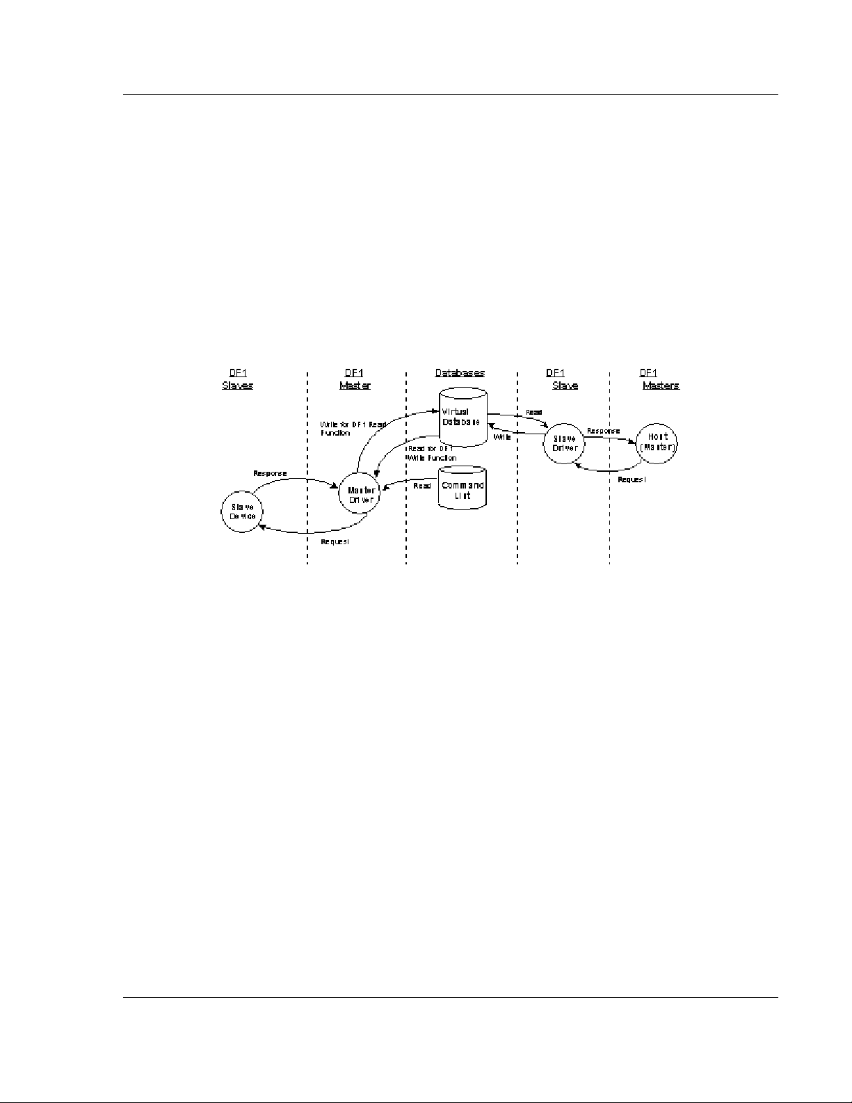
1.2.1 DF1 Serial Port Driver Access to Database
The following diagram describes the flow of data between the serial port drivers
and the internal database.
The Master driver uses the database in two ways:
1 A read command issued to a slave device by the master driver will return the
slave data into the internal database
2 A write command issued to a slave device by the master driver uses the data
in the internal database to write to the slave device
The slave driver accesses data from the internal database. External DF1 master
devices can monitor and control data in this database through these slave
port(s). Setup of the slave ports only requires the CFG file.
ProSoft Technology, Inc. Page 11 of 88
October 15, 2010
Page 12

Functional Overview DFCM ♦ ProLinx Gateway
Driver Manual DF1 Master/Slave
Page 12 of 88 ProSoft Technology, Inc.
October 15, 2010
Page 13

DFCM ♦ ProLinx Gateway Protocol Functional Specifications
DF1 Master/Slave Driver Manual
2 Protocol Functional Specifications
2.1 Functional Specifications - DF1 Master/Slave
The DF1 Master/Slave Protocol driver provides extensive support for both Master
and Slave implementations of the protocol. The serial port on the module is userconfigurable to support the DF1 protocol (Master or Slave, Error Checking,
Baud rate, and so on).
DF1 General Specifications
Internal Database 10000 registers (words) available
Communication parameters Local Station ID: 0 to 254
Ports 1 to 3 Baud Rate: 110 to 115K baud
Stop Bits: 1
Data Bits: 8
Parity: None, Even, Odd
RTS Timing delays: 0 to 65535 milliseconds
Error Checking BCC and CRC
Miscellaneous Full hardware handshaking control, providing
radio, smart modem and multi-drop support
Floating point data supported
DF1 Master
The ports on the module can be individually configured as Master ports. When
configured in master mode, the DFCM module is capable of reading and writing
data to remote DF1 devices.
DF1 Modes Full-Duplex - Master (Module generates
commands)
Half-Duplex - Polling
Command List Up to 100 commands per Master port, each fully-
configurable for function, slave address, register
to/from addressing and word/bit count
Polling of Command List User-configurable polling of commands, including
disabled, continuous, and on change of data (write
only)
Configurable Parameters per
Master port
Min Command Delay
Number of Commands
Response Timeout
Retry Count
Slave List Error Pointer
ProSoft Technology, Inc. Page 13 of 88
October 15, 2010
Page 14

Protocol Functional Specifications DFCM ♦ ProLinx Gateway
Driver Manual DF1 Master/Slave
DF1 Slave
The ports on the module can be individually configured to support the Slave
mode of the DF1 protocol. When in slave mode, the module can accept DF1
commands from a master to read/write data stored in the module’s internal
registers.
DF1 Modes Full Duplex - Slave (not peer mode)
Half Duplex - Polled
Configurable parameters per
slave port
Data Table File Start (File N[x] 0 to 999)
Data Table File Size (1 to 1000 words)
Data Table location in database (0 to 3999)
Page 14 of 88 ProSoft Technology, Inc.
October 15, 2010
Page 15

DFCM ♦ ProLinx Gateway Protocol Functional Specifications
DF1 Master/Slave Driver Manual
2.2 Serial Port Specifications
Type Specifications
Serial Ports
Serial Port Cables (DB-9M Connector) One DIN to DB-9M cable included per configurable
Port 0 RS-232/422/485: jumper selectable
Port 1, 2, 3
Protocol Ports 1, 2, 3
(Only if product includes extra serial ports)
Serial Port Isolation 2500V RMS port-to-port isolation per UL 1577.
Serial Port Protection RS-485/422 port interface lines TVS diode protected
serial port
DB-9M connector
Hardware Handshaking: RTS,CTS,DTR,DSR,DCD
RS-232/422/485: Software configurable
DB-9M connector
Hardware Handshaking: RTS,CTS,DTR,DSR,DCD
3000V DC min. port to ground and port to logic
power isolation.
at +/- 27V standoff voltage.
RS-232 port interface lines fault protected to +/- 36V
power on, +/- 40V power off.
ProSoft Technology, Inc. Page 15 of 88
October 15, 2010
Page 16

Protocol Functional Specifications DFCM ♦ ProLinx Gateway
Driver Manual DF1 Master/Slave
Page 16 of 88 ProSoft Technology, Inc.
October 15, 2010
Page 17

DFCM ♦ ProLinx Gateway DFCM Slave Driver Operation
DF1 Master/Slave Driver Manual
3 DFCM Slave Driver Operation
In This Chapter
File Simulation ....................................................................................... 18
Example Slave Port Application ............................................................ 19
Slave Port Command Support ............................................................... 20
This section discusses several characteristics in the module’s configuration and
operation that are unique to the emulated DF1 slave ports. In order to support
several types of DF1 devices, the slave ports require additional configuration
parameters. If the basic command set is used, these features need not be
considered. These features must be considered if the module has the potential of
receiving a PLC5 or SLC command function.
ProSoft Technology, Inc. Page 17 of 88
October 15, 2010
Page 18

DFCM Slave Driver Operation DFCM ♦ ProLinx Gateway
Driver Manual DF1 Master/Slave
3.1 File Simulation
The PLC5 and SLC command sets require the use of data files. These entities
are simulated in the module and are configured by the user. Data in these
processors are stored in files such as N10:, F20: and A25:. Each file has a
defined element size and length. The module simulates these files by assigning
each element to a word-size (two bytes) register in the module’s database, and
each file is set to a fixed, user-defined length. These files are mapped to the
database under user control. A discussion of each parameter related to the file
simulation is given below along with an example.
[SECTION]/Item Range Description
[DF1 PORT 0]
[DF1 PORT 1]
[DF1 PORT 2]
[DF1 PORT 3]
First File: This parameter defines the first file number recognized by
File Size: This parameter defines a constant size for all files
File Offset:
Configuration Header for Port 0
Configuration Header for Port 1
Configuration Header for Port 2
Configuration Header for Port 3
the module. If the value is set to 7, all requests for files
less than 7 will be returned as an error message. Files
greater than or equal to 7 will be processed as long as
the elements referenced are valid for the database. If a
request is received for an element beyond the last
register in the database, the module will return an error
message.
simulated by the module. If the parameter is set to 100,
all files will contain 100 elements. If the First File
parameter is set to 7 and the File Size parameter is set to
100, all files (N7:, N8:, N9...) will contain 100 elements.
This parameter defines the starting address in the
module’s internal database to be associated with the first
element in the first file to be simulated. For example, if the
First File parameter is set to 7 and the File Offset
parameter is set to 1000, file element N7:0 will
correspond to database register 1000 and N7:100 will
correspond to register 1100.
Page 18 of 88 ProSoft Technology, Inc.
October 15, 2010
Page 19

DFCM ♦ ProLinx Gateway DFCM Slave Driver Operation
DF1 Master/Slave Driver Manual
3.2 Example Slave Port Application
The example given below assumes that both ports 0 and 1 are configured as
slave ports using the following table of parameters:
Parameter Port 0 Port1
First File 7 10
File Size 200 1000
File Offset 1000 2000
The following illustration shows the file simulation feature in the module using the
configuration defined above:
Port 0 Database Register Port 1
0
200
400
600
800
N7:0
N8:0
N9:0
N10:0
N11:0
N12:0
N13:0
N14.0
N15.0
N16:0
N17:0
N18:0
N19:0
N20:0
N21:0
→
→
→
→
→
→
→
→
→
→
→
→
→
→
→
1000
1200
1400
1600
1800
2000
2200
2400
2600
2800
3000
3200
3400
3600
3800
←
←
←
←
←
←
←
←
←
←
N10:0
N10:200
N10:400
N10:600
N10:800
N11:0
N11:200
N11:400
N11:600
N11:800
ProSoft Technology, Inc. Page 19 of 88
October 15, 2010
Page 20

DFCM Slave Driver Operation DFCM ♦ ProLinx Gateway
Driver Manual DF1 Master/Slave
3.3 Slave Port Command Support
The current version of the module will respond to the following list of DF1
commands. Future releases may support more functions as required by user
applications.
Page 20 of 88 ProSoft Technology, Inc.
October 15, 2010
Page 21

DFCM ♦ ProLinx Gateway Communication Port Cables
DF1 Master/Slave Driver Manual
4 Communication Port Cables
This section contains information on the cable and pin assignments for the
ProLinx module's serial ports (RS-232/422/485). The ProLinx module will come
with one to five serial ports, depending on the configuration purchased. In all
cases, the protocol serial ports will have the same pinouts.
Example: The 5202-MNET-MCM4 module contains five serial communication ports; four
configurable protocol application ports and one Configuration/ Debug port.
The 5201-MNET-MCM module contains two serial communication ports; one configurable protocol
application port and one Configuration/Debug port.
Each physical serial port has an eight-pin Mini-DIN jack connector. A six-inch
Mini-DIN-8Male to DB-9Male adapter cable is provided for each serial port. The
DB-9M provides connections for RS-232, wired as Data Terminal Equipment
(DTE), RS-422 and RS-485. The diagrams in the following topics detail the pin
assignments for several possible electrical interface connections.
ProSoft Technology, Inc. Page 21 of 88
October 15, 2010
Page 22
Communication Port Cables DFCM ♦ ProLinx Gateway
Driver Manual DF1 Master/Slave
4.1 Serial Port Cable Connections: Multiple Port Units
The relationship between the port labeling on the front of the ProLinx module and
the application is as follows:
The following ports only exist on units with more than one application serial port
Port 1 Application Port 1 (RS-232, RS-422, or RS-485 Modes Available)
Port 2 Application Port 2 (RS-232, RS-422, or RS-485 Modes Available)
Port 3 Application Port 3 (RS-232, RS-422, or RS-485 Modes Available)
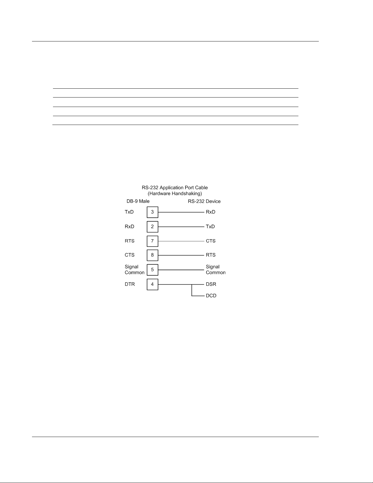
4.1.1 Port 0, 1, 2, 3: RS-232 - Null Modem (DTE with Hardware
Handshaking)
This type of connection is used when the device connected to the module
requires hardware handshaking (control and monitoring of modem signal lines;
Use CTS (page 34) parameter set to YES).
Page 22 of 88 ProSoft Technology, Inc.
October 15, 2010
Page 23
DFCM ♦ ProLinx Gateway Communication Port Cables
DF1 Master/Slave Driver Manual
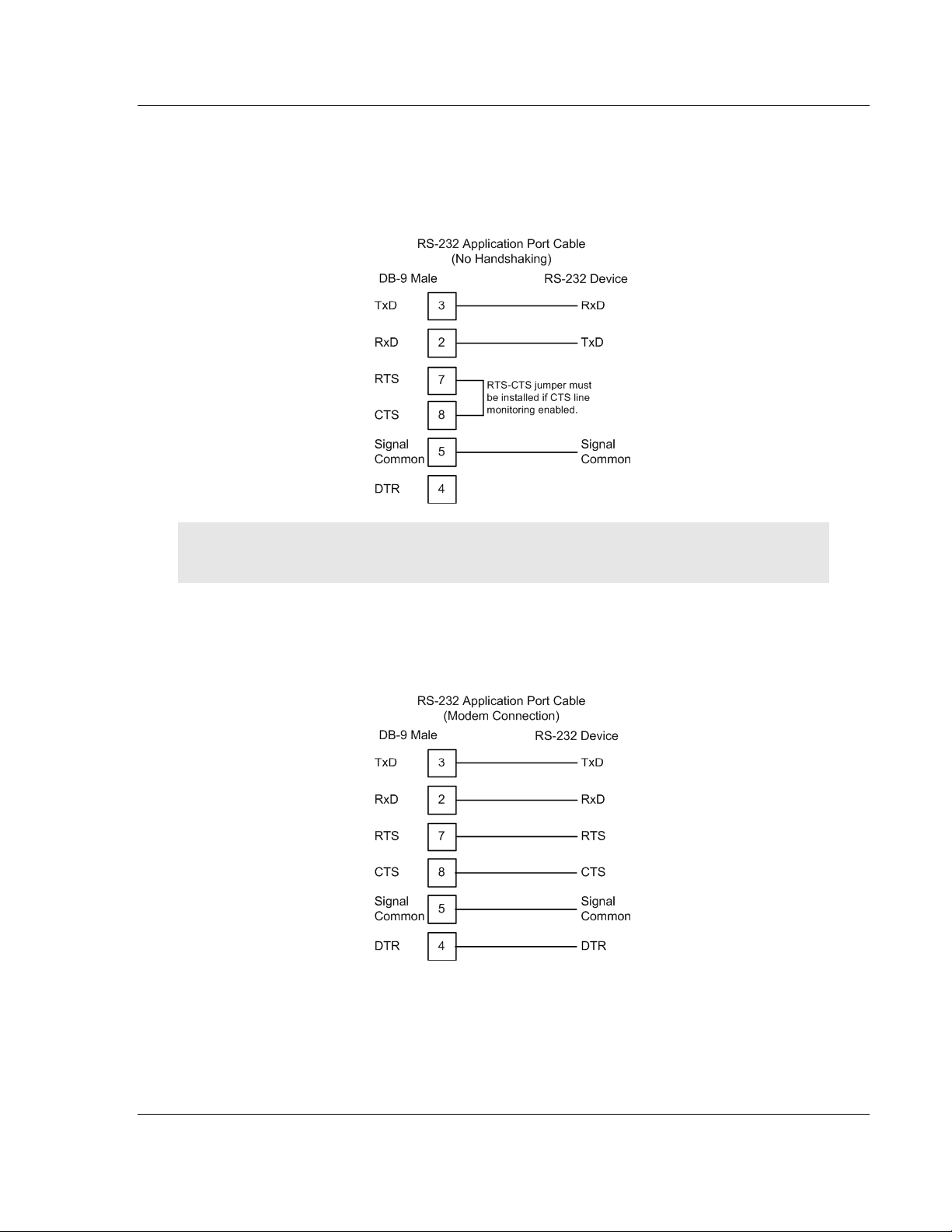
4.1.2 Port 0, 1, 2, 3: RS-232 - Null Modem (DTE without Hardware
Handshaking)
This type of connection can be used to connect the module to a computer or field
device communication port.
Note: If the port is configured with the Use CTS (page 34) set to YES, then a jumper is required
between the RTS and the CTS line on the module connection.
4.1.3 Port 0, 1, 2, 3: RS-232 - DTE to DCE Modem Connection
This type of connection is required between the module and a modem or other
communication device.
The Use CTS Line (page 34) parameter for the port configuration should be set
to YES for most modem applications.
ProSoft Technology, Inc. Page 23 of 88
October 15, 2010
Page 24
Communication Port Cables DFCM ♦ ProLinx Gateway
Driver Manual DF1 Master/Slave
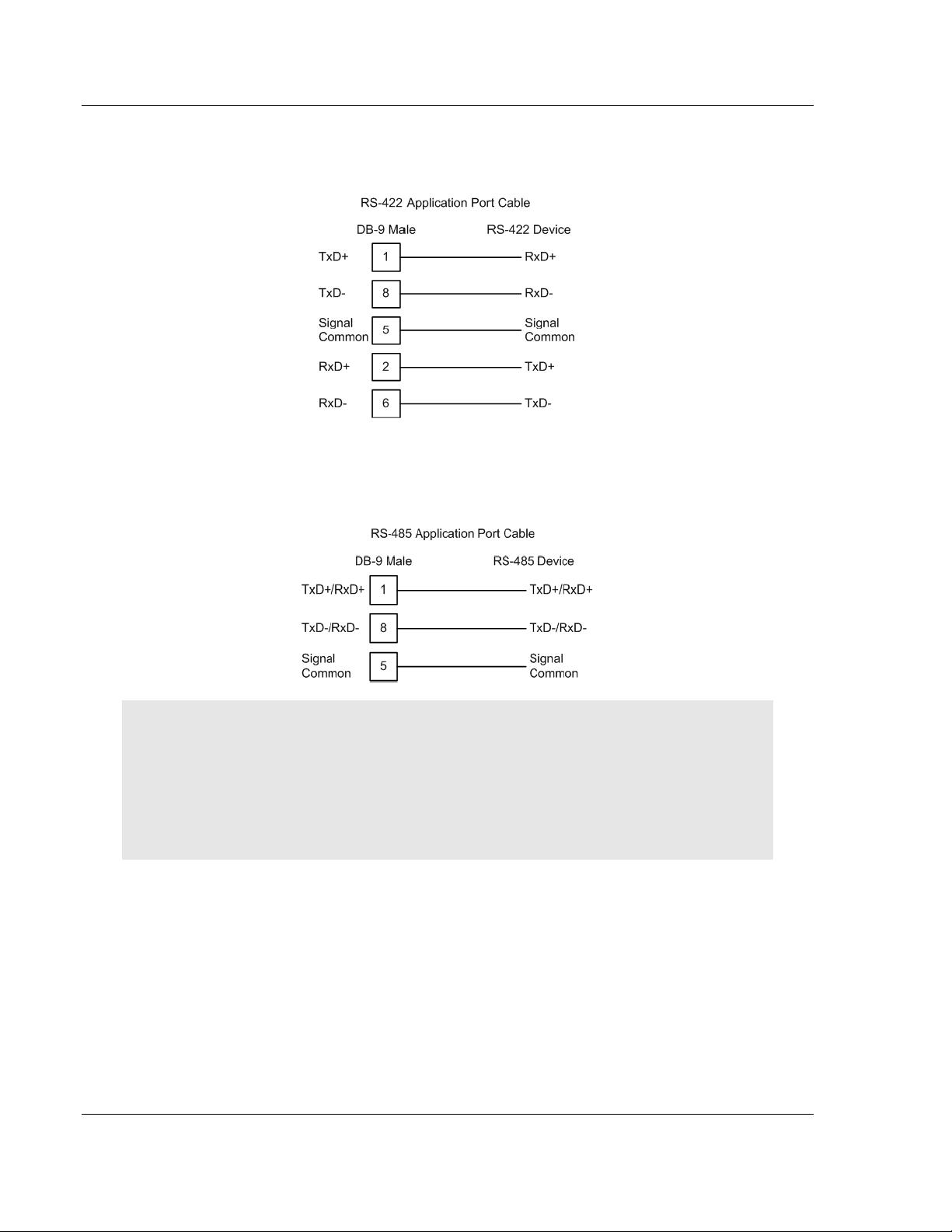
4.1.4 Port 0, 1, 2, 3: RS-422 Interface Connections
The following illustration applies when the RS-422 interface is selected.
4.1.5 Port 0, 1, 2, 3: RS-485 Interface Connections
The following illustration applies when the RS-485 interface is selected.
NOTE: This type of connection is commonly called a RS-485 half-duplex, 2-wire connection. If you
have RS-485 4-wire, full-duplex devices, they can be connected to the module's serial ports by
wiring together the TxD+ and RxD+ from the two pins of the full-duplex device to Pin 1 on the
module and wiring together the TxD- and RxD- from the two pins of the full-duplex device to Pin 8
on the module. As an alternative, you could try setting the module to use the RS-422 interface and
connect the full-duplex device according to the RS-422 wiring diagram (page 24). For additional
assistance, please contact ProSoft Technical Support.
Page 24 of 88 ProSoft Technology, Inc.
October 15, 2010
Page 25

DFCM ♦ ProLinx Gateway LED Indicators
DF1 Master/Slave Driver Manual
5 LED Indicators
In This Chapter
Base Module LEDs ................................................................................ 26
LEDs for Serial DF1 Protocol Ports ....................................................... 27
DFNT Pass-Through (Debug) Port LEDs .............................................. 28
LED indicators provide a means of monitoring the operation of the unit and
individual ports and are extremely useful for troubleshooting. In addition to port
monitoring, system configuration errors, application errors, and fault indications
are all monitored with LEDs providing alerts to possible problems. The ProLinx
Reference Guide provides more information on LEDs and troubleshooting.
ProSoft Technology, Inc. Page 25 of 88
October 15, 2010
Page 26

LED Indicators DFCM ♦ ProLinx Gateway
Driver Manual DF1 Master/Slave
5.1 Base Module LEDs
LED State Description
Power Off Power is not connected to the power terminals or source is insufficient
Green Solid Power is connected to the power terminals.
Fault Off Normal operation.
Red Solid A critical error has occurred. Program executable has failed or has
Cfg Off Normal operation.
Amber Solid The unit is in configuration mode. The configuration file is currently
Err Off Normal operation.
Flashing An error condition has been detected and is occurring on one of the
Solid Red This error flag is cleared at the start of each command attempt
to properly power the module (minimum required is 800mA at 24 Vdc)
been user-terminated and is no longer running. Press Reset p/b or
cycle power to clear error. If not, use the Debug procedures described
later in this manual.
being downloaded or, after power-up, is being read, the unit is
implementing the configuration values, and initializing the hardware.
This will occur during power cycle, or after pressing the reset button. It
also occurs after a cold/warm boot command is received.
application ports. Check configuration and troubleshoot for
communication errors.
(Master/Client) or on each receipt of data (slave/adapter/server); so, if
this condition exists, it indicates a large number of errors are occurring
in the application (due to bad configuration) or on one or more ports
(network communication failures).
Page 26 of 88 ProSoft Technology, Inc.
October 15, 2010
Page 27

DFCM ♦ ProLinx Gateway LED Indicators
DF1 Master/Slave Driver Manual
5.2 LEDs for Serial DF1 Protocol Ports
Troubleshooting the operation of the serial DF1 protocol ports can be performed
using several methods.
The first and quickest is to scan the LEDs on the module to determine the
existence and possibly the cause of a problem. This section provides insight into
the operation of the Serial Port status LEDs.
Some ProLinx modules will include three extra serial ports. Each of these serial
ports has two LEDs indicating status.
LED Color Description
Port 0 - ACT
Port 1 - ACT
Port 2 - ACT
Port 3 - ACT
Port 0 - ERR
Port 1 - ERR
Port 2 - ERR
Port 3 - ERR
Off No activity on the port.
Green
Flash
Off Normal state. When off and Port Active led is
Amber
On or Flashing
The port is either actively transmitting or
receiving data
indicating activity, there are no communication
errors
Activity on this led indicates some
communication error was detected, either during
transmit or receive. To determine the exact error,
connect the Debug terminal to the Debug port.
Note that the meaning of the other LEDs on the unit can be found in the Product
Manual for the specific module that is being debugged.
ProSoft Technology, Inc. Page 27 of 88
October 15, 2010
Page 28

LED Indicators DFCM ♦ ProLinx Gateway
Driver Manual DF1 Master/Slave
5.3 DFNT Pass-Through (Debug) Port LEDs
LED State Description
Fault Off Normal operation.
Red Solid If the CFG LED is on, the Debug/Configuration mode is active on the
Debug port.
If the CFG LED is off, a critical error has occurred. Program executable
has failed or has been user-terminated and is no longer running. Press
R
ESET
p/b or cycle power to clear error. If not, use the Debug
procedures described later in this manual.
CFG Off Normal operation.
Amber Solid If the Fault LED is on, the Debug/Configuration Mode is active on the
Debug port.
If the Fault LED is off, the unit is in the configuration mode. The
configuration file is being read and the unit is implementing the
configuration values and initializing the hardware. This will occur during
power cycle, or after pressing R
cold/warm boot command is received.
ESET
pushbutton. It also occurs after a
Page 28 of 88 ProSoft Technology, Inc.
October 15, 2010
Page 29

DFCM ♦ ProLinx Gateway DFCM Protocol Configuration
DF1 Master/Slave Driver Manual
6 DFCM Protocol Configuration
In This Chapter
[DF1 Pass-Through Port]....................................................................... 30
[DF1 Port x] ........................................................................................... 33
DF1 Master Configuration ..................................................................... 36
DF1 Slave Configuration ....................................................................... 37
[DF1 PORT x COMMANDS] .................................................................. 38
The following is excerpted from a full configuration file showing typical examples
of the DF1 port configurations. In this example, one port has been setup as a
master and the other as a slave. This example should serve only to give the
programmer an idea of how a CFG file is structured. Complete configuration files
are shipped on each unit and are available for download from the
www.prosoft-technology.com web site for each of the products. These files can
serve as an excellent starting point for any project.
ProSoft Technology, Inc. Page 29 of 88
October 15, 2010
Page 30

DFCM Protocol Configuration DFCM ♦ ProLinx Gateway
Driver Manual DF1 Master/Slave
6.1 [DF1 Pass-Through Port]
This section describes the use and configuration of the pass-through mode on
the Debug/Configuration port of DFCM based modules.
Port 0 can operate either as:
Pass-Through from the Debug to Port 0
Standard Debug/Configuration operation on the Debug Port.
To enable Pass-Through mode:
1 Port 0 on the module must be configured as a DF1 master port using the DF1
full-duplex protocol.
2 The Enabled parameter in the [Pass-Through Port] Section must be set to
"Yes"
The communication parameters for the two ports need not match, as the
module's program will convert the messages. The illustration above displays the
use of the pass-through port and Debug/Configuration port.
Page 30 of 88 ProSoft Technology, Inc.
October 15, 2010
Page 31

DFCM ♦ ProLinx Gateway DFCM Protocol Configuration
DF1 Master/Slave Driver Manual
6.1.1 Configuration Values
The module must be configured properly in order to use the pass-through mode.
Port 0 must be configured as a DF1 master port using the full-duplex protocol.
The termination type (BCC or CRC) set on Port 0 is used for the pass-through
port. The module's configuration file must contain the [Pass-Through Port]
section with the Enabled parameter set to "Yes".
[Section]/Item Range Description
[Pass-Through
Port]
Enabled: Yes or No This parameter specifies if the pass-through port is to be utilized
Local Station ID: 0 to 255 This parameter specifies the local station ID for all DF1 messages
Protocol: Full
Baud Rate: This is the baud rate to be used on the port. Enter the baud rate
Parity: None,
Data Bits: 7 or 8 This parameter sets the number of data bits for each word used
Stop Bits: 1 or 2 This parameter sets the number of stop bits for each data value
RTS On: 0 to 65535 This parameter sets the number of milliseconds to delay after RTS
RTS Off: 0 to 65535 This parameter sets the number of milliseconds to delay after the
Use CTS Line: Yes or No This parameter specifies if the CTS modem control line is to be
Request Timeout: 0 to 65535 This parameter specifies the number of milliseconds to wait for a
Start header for DF1 pass-through port definition.
in the application. Additionally, Port 0 must be configured
correctly. Set the parameter to Yes to enable the feature and No
to disable feature.
sent to this port. A value of 255 will cause the slave address to be
ignored and the address issued in the master request packet to
use as the slave ID. The application will only accept messages
with this node address.
Full duplex, Half-duplex
Duplex or
Half
Duplex
as a value. For example, to select 19K baud, enter 19200.
This is the Parity code to be used for the port. The coded values
Odd, or
Even
are as follows: None, Odd, Even.
by the protocol.
sent.
is asserted before the data will be transmitted.
last byte of data is sent before the RTS modem signal will be set
low.
used. If the parameter is set to N, the CTS line will not be
monitored. If the parameter is set to Yes, the CTS line will be
monitored and must be high before the module will send data.
Normally, this parameter is required when half-duplex modems
are used for communication (2-wire).
complete request message. The timer is started after the DLE-
STX character sequence is received for the full-duplex protocol or
the DLE-SOH sequence for the half-duplex protocol. If the timer
expires, the current request message will be aborted.
ProSoft Technology, Inc. Page 31 of 88
October 15, 2010
Page 32

DFCM Protocol Configuration DFCM ♦ ProLinx Gateway
Driver Manual DF1 Master/Slave
[Section]/Item Range Description
Busy Timeout: 0 to 65535 This parameter specifies the number of milliseconds to wait for the
DF1 master port to become available. If the DF1 master port is
processing a command list request, the busy flag will be set. The
flag will remain busy until the communication transaction is
complete. If the port does not become available before the busy
timeout expires, the message will be aborted. If the master port
becomes available before this timeout expires, the request will be
routed to the master port.
ACK Timeout: 0 to 65535 This parameter specifies the number of milliseconds to wait for a
DLE-ACK character sequence after a response is issued.
Retry Count: 0 to 65535 This parameter specifies the number of attempts for each
response message. If a message fails, it will be retried up to the
count specified.
6.1.2 Switching between Pass-Through and Debug/Configuration
When the module’s program is initialized, it will be set with the Debug/
Configuration port in pass-through mode. A DF1 master device (that is,
PanelView or HMI) or programming device (that is, PC running RSLogix
software) can be connected to the Debug/Configuration port with the messages
routed through the port to Port 0 on the module. The module’s command polling
on Port 0 will be interrupted as messages from the pass-through port are
handled.
To switch the module to Debug/Configuration mode on the port, follow these
steps:
1 Connect the terminal device (personal computer running a terminal emulator)
to the Debug/Configuration port.
2 Start the terminal emulator software.
3 Change the baud rate to match the pass-through configuration.
4 Press and hold the [D] key on the keyboard until the following message
appears:
Change to 57.6 Kb Baud…
5 Change the baud rate on the terminal emulator software to 57.6 baud.
6 Press [?] key to display the module’s Debug/Configuration main menu.
The Debug/Configuration is now available. Refer to the ProLinx Reference Guide
for menu commands and other information).
To return the port to pass-through mode, press [*] (Shift-8) on the main menu.
When the message Exiting Debug Configuration Mode… appears, disconnect
the personal computer from the port and connect the DF1 master device to the
port.
Debug Port LED Indications
The following table shows the status indicated by the module’s LEDs. Note that
in the pass-through mode, the FLT and CFG LEDs act normally, indicating fault
and configuration problems.
Mode FLT LED CFG LED
Pass-Through Active OFF OFF
Debug Mode Active ON ON
Page 32 of 88 ProSoft Technology, Inc.
October 15, 2010
Page 33

DFCM ♦ ProLinx Gateway DFCM Protocol Configuration
DF1 Master/Slave Driver Manual
6.2 [DF1 Port x]
The [DF1 PORT x] sections of the configuration file set the DF1 port type,
communication parameters, define the protocol specifics and set the command
list parameters. The parameters are the same for each port. Each DF1 Port also
has its own Command List.
6.2.1 Enabled
This parameter specifies if the port will be used. If the parameter is set to No, the
port is disabled. If the parameter is set to Yes, the port is enabled.
6.2.2 Type
Type : Master #M=Master, S=Slave
This parameter defines if the port will emulate a master or a slave device. Enter
Master if the port is to emulate a master device or Slave if the port is to emulate a
slave device.
6.2.3 Local Station ID
This parameter specifies the local station ID for all DF1 messages sent from this
master port. A value of 255 is not permitted as this is the broadcast address.
Enter a value in the range of 0 to 254.
6.2.4 Protocol
Protocol : Full #F=Full-Duplex, H=Half-Duplex
This parameter specifies the DF1 protocol to be used on the port. Enter Full for
full-duplex communications or Half for half-duplex communications.
6.2.5 Termination Type
Termination Type : CRC #B=BCC, C=CRC
This parameter specifies error checking for all DF1 messages. Enter CRC or
BCC.
6.2.6 Baud Rate
This is the baud rate to be used on the port. Enter the baud rate as a value. For
example, to select 19K baud, enter 19200.
6.2.7 Parity
None, Odd, Even
Parity is a simple error checking algorithm used in serial communication. This
parameter specifies the type of parity checking to use.
All devices communicating through this port must use the same parity setting.
ProSoft Technology, Inc. Page 33 of 88
October 15, 2010
Page 34

DFCM Protocol Configuration DFCM ♦ ProLinx Gateway
Driver Manual DF1 Master/Slave
6.2.8 Data Bits
7 or 8
This parameter sets the number of data bits for each word used by the protocol.
All devices communicating through this port must use the same number of data
bits.
6.2.9 Stop Bits
1 or 2
Stop bits signal the end of a character in the data stream. For most applications,
use one stop bit. For slower devices that require more time to re-synchronize,
use two stop bits.
All devices communicating through this port must use the same number of stop
bits.
6.2.10 Minimum Response Delay
0 to 65535
This parameter is used only when the port is configured as a slave. It sets the
number of milliseconds to wait before responding to a command received on the
port from a remote Master. This delay is sometimes required to accommodate
slower Master devices.
6.2.11 RTS On
0 to 65535 milliseconds
This parameter sets the number of milliseconds to delay after Ready To Send
(RTS) is asserted before data will be transmitted.
6.2.12 RTS Off
0 to 65535 milliseconds
This parameter sets the number of milliseconds to delay after the last byte of
data is sent before the RTS modem signal will be set low.
6.2.13 Use CTS Line
YES or NO
This parameter specifies if the Clear To Send (CTS) modem control line is to be
used or not. If the parameter is set to NO, the CTS line will not be monitored. If
the parameter is set to YES, the CTS line will be monitored and must be high
before the module will send data. Normally, this parameter is required when halfduplex modems are used for communication (2-wire). This procedure is
commonly referred to as hardware handshaking.
Page 34 of 88 ProSoft Technology, Inc.
October 15, 2010
Page 35

DFCM ♦ ProLinx Gateway DFCM Protocol Configuration
DF1 Master/Slave Driver Manual
6.2.14 Response Timeout
Number of milliseconds to wait for response to command. The value is set
depending upon the communication network used and the expected response
time of the slowest device on the network. Valid values are 0 to 5000
milliseconds.
6.2.15 Retry Count
0 to 10
This parameter specifies the number of times a command will be retried if it fails.
ProSoft Technology, Inc. Page 35 of 88
October 15, 2010
Page 36

DFCM Protocol Configuration DFCM ♦ ProLinx Gateway
Driver Manual DF1 Master/Slave
6.3 DF1 Master Configuration
The following parameters are required only if the port is to be configured as a
Master.
6.3.1 ENQ Delay
ENQ Delay : 0 #0-65535 milliseconds before DLE-ENQ sent
This parameter specifies the number of milliseconds to wait after a DLE-ACK is
received from a slave using half-duplex mode before the DLE-ENQ request is
made for data. Enter a value in the range of 0 to 65535 milliseconds.
6.3.2 Minimum Command Delay
This parameter specifies the number of milliseconds to wait between issuing
each command. This delay value is not applied to retries.
6.3.3 Error Delay Count
Error Delay Count : 100 #0-65535 Command cycle count if error
This parameter specifies the number of polls to be skipped on the slave before
trying to re-establish communications. After the slave fails to respond, the master
will skip commands to be sent to the slave the number of times entered in this
parameter. Enter a value in the range of 0 to 65535.
6.3.4 Command Error Pointer
Command Error Pointer : 3000 #Cmd Error list data (-1=ignore)
This parameter sets the address in the internal database where the command
error data will be placed. If the value is set to -1, the data will not be transferred
to the database. Enter a value from 0 to 4999.
6.3.5 Slave List Pointer
Slave List Pointer : 3100 #Slave status list data (-1=ignore)
This parameter specifies the starting address in the virtual database where the
256 slave status values will be written. If the parameter is set to -1, the slave data
will not be placed in the database. Enter a value in the range of -1 to 4743.
Page 36 of 88 ProSoft Technology, Inc.
October 15, 2010
Page 37

DFCM ♦ ProLinx Gateway DFCM Protocol Configuration
DF1 Master/Slave Driver Manual
6.4 DF1 Slave Configuration
The following parameters are required only if the port is to be configured as a
Slave.
6.4.1 First File
First File : 7 #First file number for SLC simulation
This parameter is used when a request for a file is received on the
communication port. This field is required when responding to PLC5 and SLC
DF1 commands. Use this parameter to define the virtual file(s) to be simulated on
the module. Enter a value in the range of 0 to 100.
6.4.2 File Size
Range 1 to 1000
This parameter specifies the size of each file to be simulated on the module. All
files simulated are defined to have the same assigned size.
6.4.3 File Offset
This parameter sets the database register location of the first element in the first
file simulated in the module. All offsets in the first file and subsequent files will be
computed using the address specified. Enter a value in the range of 0 to 4999.
ProSoft Technology, Inc. Page 37 of 88
October 15, 2010
Page 38

DFCM Protocol Configuration DFCM ♦ ProLinx Gateway
Driver Manual DF1 Master/Slave
6.5 [DF1 PORT x COMMANDS]
The [DF1 PORT 0 COMMANDS], [DF1 PORT 1 COMMANDS], [DF1 PORT 2
COMMANDS] and [DF1 PORT 3 COMMANDS] sections of the CFG file set the
serial master port command lists. These lists poll slave devices attached to the
master ports. The module supports numerous commands.
The command list is formatted differently than the other sections of the
configuration file. Commands are present in a block between the labels START
and END. These labels inform the program where the list resides. The module's
program will parse all commands after the START label until it reaches the END
label.
6.5.1 Command List Overview
In order to interface the ProLinx module with slave devices, you must construct a
command list. The commands in the list specify the slave device to be
addressed, the function to be performed (read or write), the data area in the
device to interface with and the registers in the internal database to be
associated with the device data. There is a separate command list for each
master port, with up to 100 commands allowed per master port. The command
list is processed from top (command #0) to bottom. A poll interval parameter is
associated with each command to specify a minimum delay time in seconds
between the issuance of a command. If the user specifies a value of 10 for the
parameter, the command will be executed no more frequently than every 10
seconds.
Write commands have a special feature, as they can be set to execute only if the
data in the write command changes. If the register data values in the command
have not changed since the command was last issued, the command will not be
executed. If the data in the command has changed since the command was last
issued, the command will be executed. Use of this feature can lighten the load on
the DF1 network. In order to implement this feature; set the enable code for the
command to a value of 2.
If the module is configured for the DF1 half-duplex protocol, the module can act
as a master device routing messages between attached slave devices. This
peer-to-peer communication is defined in the DF1 protocol specification. The
master polls each DF1 slave device until no more data is available from the
device. Response messages from the slaves that have a destination address that
do not match the module are routed with a request message header back out
onto the network. This facility offers communication between the slave devices
for control and data monitoring. This feature is not available if the module is
configured for DF1 full-duplex mode (point-to-point).
The module supports numerous commands. This permits the module to interface
with a wide variety of DF1 protocol devices. This includes PLC2, PLC5, SLC-500
series, MicroLogix and ControlLogix processors. Additionally, other devices
supplied by that use the DF1 protocol are supported.
Page 38 of 88 ProSoft Technology, Inc.
October 15, 2010
Page 39

DFCM ♦ ProLinx Gateway Commands Supported by the Module
DF1 Master/Slave Driver Manual
7 Commands Supported by the Module
The format of each command in the list depends on the function being executed.
To simplify command construction, the module uses its own set of function codes
to associate a command with a DF1 command/function type. The tables below
list the functions supported by the module:
Basic Command Set Functions
Function
Code
1 0x00 N/A Protected Write X
2 0x01 N/A Unprotected Read X X
3 0x02 N/A Protected Bit Write X
4 0x05 N/A Unprotected Bit Write X
5 0x08 N/A Unprotected Write X X
Command Function Definition PLC5 SLC500 &
MicroLogix
Powermonitor II
ControlLogix
X
X
X
X
X
PLC-5 Command Set Functions
Function
Command Function Definition PLC5 SLC500 &
Code
100 0x0F 0x00 Word Range Write
(Binary Address)
101 0x0F 0x01 Word Range Read
(Binary Address)
102 0x0F 0x26 Read-Modify-Write
(Binary Address)
150 0x0F 0x00 Word Range Write
(ASCII Address)
151 0x0F 0x01 Word Range Read
(ASCII Address)
152 0x0F 0x26 Read-Modify-Write
(ASCII Address)
Power-
MicroLogix
X
X
X
X
X
X
monitor II
X
X
X
X
X
X
ControlLogix
ProSoft Technology, Inc. Page 39 of 88
October 15, 2010
Page 40

Commands Supported by the Module DFCM ♦ ProLinx Gateway
X
X
X
Driver Manual DF1 Master/Slave
SLC-500 Command Set Functions
Function
Command Function Definition PLC5 SLC500 &
Code
501 0x0F 0xA1 Protected Typed
MicroLogix
Powermonitor II
ControlLogix
X
Logical Read With
Two Address Fields
502 0x0F 0XA2 Protected Typed
X X X
Logical Read With
Three Address Fields
509 0x0F 0XA9 Protected Typed
X
Logical Write With
Two Address Fields
510 0x0F 0XAA Protected Typed
X X X
Logical Write With
Three Address Fields
511 0x0F 0XAB Protected Typed
X
Logical Write With
Mask (Three Address
Fields)
Page 40 of 88 ProSoft Technology, Inc.
October 15, 2010
Page 41

DFCM ♦ ProLinx Gateway Commands Supported by the Module
DF1 Master/Slave Driver Manual
Each command list record has the same general format. The first part of the
record contains the information relating to the communication module and the
second part contains information required to interface to the DF1 slave device.
The PLC-5 and SLC-500 command set require the use of files. These files are
emulated in the module. The module defines these files each as containing 200word registers that overlay the internal database. The following table shows the
relationship of the files to the user data area of the internal database:
File
N7:0
N8:0
N9:0
N10:0
N11:0
N12:0
N13:0
N14:0
N15:0
N16:0
N17:0
N18:0
N18:0
N20:0
N21:0
N22:0
N23:0
N24:0
N25:0
N26:0
N27:0
N28:0
N29:0
N30:0
N31:0
N32:0
→→→→
→
→
→
→
→
→
→
→
→
→
→
→
→
→
→
→
→
→
→
→
→
→
→
→
→
→
Database Register
0
200
400
600
800
1000
1200
1400
1600
1800
2000
2200
2400
2600
2800
3000
3200
3400
3600
3800
4000
4200
4400
4600
4800
5000
Note: The way these files are emulated depends of the First File and File Size parameters. The
previous example shows using the First File parameter set to 7 and the File Size parameter set to
200.
ProSoft Technology, Inc. Page 41 of 88
October 15, 2010
Page 42

Commands Supported by the Module DFCM ♦ ProLinx Gateway
Driver Manual DF1 Master/Slave
In order to retrieve data from the modules database register 200, the remote
master would issue a command using the address N8:0. In order to interface with
database base register 405, the remote master would use the address N9:5. The
following table outlines the complete file emulation for the module:
Register Range File Start File End Content Size
0 to 4999 N7:0 N31:199 User Data 5000
5000 to 5009 N32:0 N32:9 Backplane Configuration 10
5010 to 5039 N32:10 N32:39 Port 1 Setup 30
5040 to 5069 N32:40 N32:69 Port 2 Setup 30
5070 to 5199 N32:70 N32:199 Reserved 130
5200 to 6399 N33:0 N38:199 Port 1 Commands 1200
6400 to 7599 N39:0 N44:199 Port 2 Commands 1200
7600 to 7700 N45:0 N45:199 Misc. Status Data 200
7800 to 7999 N46:0 N46:199 Command Control 200
8000 to 9999 N47:0 N56:199 Reserved 2000
All the data in the module is available to a remote host. This permits the host
device to remotely configure the module and view the status data.
7.1.1 Command Entry Formats
Note: The format of each command in the list depends on the function being executed. Refer to
the Reference chapter for a complete discussion of the DF1 commands supported by the module
and of the structure and content of each command.
The following table shows the structure of the configuration data necessary for
each of the supported commands.
Page 42 of 88 ProSoft Technology, Inc.
October 15, 2010
Page 43

DFCM ♦ ProLinx Gateway Commands Supported by the Module
DF1 Master/Slave Driver Manual
The first part of the record is the module Information, which relates to the ProLinx
module and the second part contains information required to interface to the
slave device. Refer to the slave device documentation for a full discussion of
each function.
Command list example:
[DF1 Port 1 Commands]
# The file contains examples for a SLC 5/03 processor.
#
START
# 1 2 3 4 5 6 7 8 9 10 11
# Internal Poll Swap Node Func File File Elm Sub
# Enable Address Interval Count Code Address Code Type # # Elm
1 1510 0 5 0 3 501 N 10 10
0 1515 0 2 0 3 509 N 10 0
1 1500 0 10 0 3 502 N 10 0 0
END
Parameter Range Description
Enable 0, 1, 2, 999 This field defines whether the command is to be executed and
under what conditions.
Value Description
0 The command is disabled and will not be executed in
the normal polling sequence.
1 The command is executed each scan of the command
list if the Poll Interval Time is set to zero. If the Poll
Interval time is set, the command will be executed,
when the interval timer expires.
2 The command will execute only if the internal data
associated with the command changes. This value is
valid only for write commands.
999 Issues a poll request to indicated slaves. This
command can be used to implement a slave-to-slave
network or an RBE based network
Internal
Address
Poll Interval 0 to 65535 This parameter specifies the minimum interval to execute
Count Message
0 to 3999 This field specifies the internal database register to be associated
with the command.
For Read functions, the data read from the slave device will be
placed starting at the register value entered in this field.
For write functions, the data written to the slave device will be
sourced from the address specified.
continuous commands (Enable code of 1). The parameter is
entered in units of seconds. Therefore, if a value of 10 is entered
for a command, the command will execute no more frequently than
every 10 seconds.
This parameter specifies the number of registers or digital points to
dependent
be associated with the command. Functions 5 and 6 ignore this
field as they only apply to a single data point.
For Binary data functions, this parameter sets the number of digital
points (inputs or coils) to be associated with the command.
For word or register functions, this parameter sets the number of
registers to be associated with the command.
ProSoft Technology, Inc. Page 43 of 88
October 15, 2010
Page 44

Commands Supported by the Module DFCM ♦ ProLinx Gateway
Driver Manual DF1 Master/Slave
Parameter Range Description
Swap Code 0, 1, 2, 3 This parameter defines if the data received from the slave is to be
ordered differently than received from the slave device. This
parameter is helpful when dealing with floating-point or other multiregister values, as there is no standard method of storage of these
data types in slave devices. This parameter can be set to order the
register data received in an order useful by other applications. The
following table defines the values and their associated operations:
Node Address 1 to 255
(255 =
broadcast)
Function Code See
Reference
section
File Type
File Number
Elem #
Sub Elem #
Swap
Code
0 None: No Change is made in the byte ordering (1234
1 Words: The words are swapped (1234=3412)
2 Words & Bytes - The words are swapped then the
3 Bytes: The bytes in each word are swapped
This parameter specifies the slave node address on the network to
be considered. Values of 1 to 255 are permitted. If the value is set
to 255, the command will be a broadcast message on the network.
The DF1 protocol permits broadcast commands for write
operations. Do not use this node address for read operations.
These parameters specify the function to be executed by the
command. The Reference chapter in this Manual describes the
meaning of these values for each of the available supported
commands. Following is a complete list of the command supported
by the Master driver.
ProLinx Function Code Listing
Basic Command Set
Protected Write
Unprotected Read
Protected Bit Write
Unprotected Bit Write
Unprotected Write
PLC-5 Command Set
Word Range Write (Binary Address)
Word Range Read (Binary Address)
Read-Modify-Write (Binary Address)
Word Range Write (ASCII Address)
Word Range Read (ASCII Address)
Read-Modify-Write (ASCII Address)
SLC Command Set
Prot Typed Read with 2 addr fields
Prot Typed Read with 3 addr fields
Prot Typed Write with 2 addr fields
Prot Typed Write with 3 addr fields
Prot Typed Write with Mask 3 addr fields
Description
= 1234)
bytes in each word are swapped (1234=4321)
(1234=2143)
Page 44 of 88 ProSoft Technology, Inc.
October 15, 2010
Page 45

DFCM ♦ ProLinx Gateway Reference
DF1 Master/Slave Driver Manual
8 Reference
In This Chapter
Serial Port Protocol Error/Status Data ................................................... 46
Error Codes ........................................................................................... 50
DF1 Configuration Error Word ............................................................... 53
DF1 Command Set For ProSoft Technology Communication Modules . 54
DF1 Command List Form ...................................................................... 69
Moving Data .......................................................................................... 70
5102-DFS3-DFM Configuration Information .......................................... 71
ProSoft Technology, Inc. Page 45 of 88
October 15, 2010
Page 46

Reference DFCM ♦ ProLinx Gateway
Driver Manual DF1 Master/Slave
8.1 Serial Port Protocol Error/Status Data
The second and most thorough troubleshooting method for debugging the
operation of the DFCM driver (and the module in general) is the powerful Debug
port on the module which provides much more complete access to the internal
operation and status of the module. Accessing the Debug capabilities of the
module is accomplished easily by connecting a PC to the Debug port and loading
a terminal program such as ProSoft Configuration Builder or HyperTerminal.
8.1.1 Viewing Error and Status Data
The following topics describe the register addresses that contain protocol error
and status data. Viewing the contents of each register is accomplished using the
Database View option. The use of this option and its associated features are
described in detail in the ProLinx Reference Guide.
8.1.2 DF1 Error and Status Data Area Addresses
DF1 error and status data are stored in registers based on the DF1 port
configuration. Starting register addresses are shown in the following table.
DF1 Port Starting Address
0 6300
1 6700
2 7100
3 7500
Note: None of the addresses are available in the DF1 address range. In order to view them, the
data must be moved using the Data Map section of the configuration file. Refer to Moving Data
(page 70) for an example of how to move data to the DF1 address range.
Page 46 of 88 ProSoft Technology, Inc.
October 15, 2010
Page 47

DFCM ♦ ProLinx Gateway Reference
DF1 Master/Slave Driver Manual
8.1.3 DF1 Ports - Error/Status Data
The serial port (DF1 Master/Slave) Error and Status Data areas are discussed in
this section. The Error Status Pointer value is configured in the CFG file within
each of the individual [DF1 PORT X] sections.
The data area is initialized with zeros whenever the module is initialized. This
occurs during a cold-start (power-on), reset (reset push-button pressed) or a
warm-boot operation (commanded or loading of new configuration).
Example Internal
Database Address
6300 0 Number of Command Requests
6301 1 Number of Command Responses
6302 2 Number of Command Errors
6303 3 Number of Requests
6304 4 Number of Responses
6305 5 Number of Errors Sent
6306 6 Number of Errors Received
6307 7 Configuration Error Word
6308 8 Current Error Code
6309 9 Last Error Code
Offset Description
Refer to the following Error Codes section to interpret the status/error codes
present in the data area.
8.1.4 Master Port: Command Errors
The individual command errors for each master port are returned to the address
locations specified in the following table.
DF1 Port Address Range
0 6310 to 6409
1 6710 to 6809
2 7110 to 7209
3 7510 to 7609
The first word in the register location defined contains the status/error code for
the first command in the port’s command list. Each successive word in the
command error list is associated with the next command in the list.
Refer to Error Codes to interpret the status/error codes present in the data area.
ProSoft Technology, Inc. Page 47 of 88
October 15, 2010
Page 48

Reference DFCM ♦ ProLinx Gateway
Driver Manual DF1 Master/Slave
Example DF1 Port 1 Command List Errors
Internal Database
Address (Example)
6310 0 Command #0 Error Status
6311 1 Command #1 Error Status
6312 2 Command #2 Error Status
6313 3 Command #3 Error Status
6314 4 Command #4 Error Status
. .
. .
. .
6407 97 Command #97 Error Status
6408 98 Command #98 Error Status
6409 99 Command #99 Error Status
Offset Description
Note that the values in the Command List Error Status tables are initialized to
zero (0) at power-up, cold boot and during warm boot.
8.1.5 Master Port: DF1 Slave List Status
Each slave polled in the command list on the DF1 master ports has a reserved
word value for a status code. This status data list can be read using the
Configuration/Debug Port and can be placed in the module’s internal database.
The first word in the register location defined contains the status code for the
DF1 slave node address 0. Each successive word in the list is associated with
the next node up to slave node 255.
Slaves attached to the master port can have one of the following states:
0 The slave is inactive and not defined in the command list for the master port.
1 The slave is actively being polled or controlled by the master port and
communication is successful.
2 The master port has failed to communicate with the slave device. Communication
with the slave is suspended for a user defined period based on the scanning of the
command list.
Slaves are defined to the system when the module initializes the master
command list. Each slave defined will be set to a state value of 1 in this initial
step. If the master port fails to communicate with a slave device (retry count
expired on a command), the master will set the state of the slave to a value of 2
in the status table. This suspends communication with the slave device for a user
specified scan count (Error Delay Counter value in the configuration). Each time
a command in the list is scanned that has the address of a suspended slave, the
delay counter value will be decremented. When the value reaches zero, the slave
state will be set to 1. This will enable polling of the slave.
Page 48 of 88 ProSoft Technology, Inc.
October 15, 2010
Page 49

DFCM ♦ ProLinx Gateway Reference
DF1 Master/Slave Driver Manual
The individual Slave List Status errors for each DF1 port are returned to the
address locations specified in the following table.
DF1 Port Address Range
0 6410 to 6665
1 6810 to 7065
2 7210 to 7465
3 7610 to 7865
Example DF1 Port 1 Slave List Status Example
Internal Database
Address (Example)
6410 0 Slave #0 Status
6411 1 Slave #1 Status
6412 2 Slave #2 Status
6413 3 Slave #3 Status
6414 4 Slave #4 Status
. .
. .
. .
6663 253 Slave #253 Status
6664 254 Slave #254 Status
6665 255 Slave #255 Status
Offset Description
The example addresses shown above assumes DF1 Port 1. Note that each
master port will have one of these status data blocks available in the internal
database, each individually located with a separate address.
Note that the values in the Slave List Status tables are initialized to zero (0) at
power-up, cold boot and during warm boot.
ProSoft Technology, Inc. Page 49 of 88
October 15, 2010
Page 50

Reference DFCM ♦ ProLinx Gateway
Driver Manual DF1 Master/Slave
8.2 Error Codes
The module error codes are listed in this section. Error codes returned from the
command list process are stored in the command list error memory region. A
word is allocated for each command in the memory area. The error codes are
formatted in the word as follows: The least-significant byte of the word contains
the extended status code and the most-significant byte contains the status code.
Use the error codes returned for each command in the list to determine the
success or failure of the command. If the command fails, use the error code to
determine the cause of failure.
Note: The Module Specific error codes (not DF1 compliant) are returned from within the module
and never returned from an attached DF1 slave device. These are error codes that are part of the
DF1 protocol or are extended codes unique to this module. The standard DF1 error codes can be
found in the DF1 Protocol and Command Set Reference Manual (Publication 1770-6.5.16) from
Rockwell Automation. The most common errors for the DF1 protocol are shown in the following
tables:
8.2.1 Local STS Error Codes
Code (Int) Code (Hex) Description
0 0x0000 Success, no error
256 0x0100 DST node is out of buffer space
512 0x0200 Cannot guarantee delivery (Link Layer)
768 0x0300 Duplicate token holder detected
1024 0x0400 Local port is disconnected
1280 0x0500 Application layer timed out waiting for response
1536 0x0600 Duplicate node detected
1792 0x0700 Station is offline
2048 0x0800 Hardware fault
8.2.2 Remote STS Error Codes
Code (Int) Code (Hex) Description
0 0x0000 Success, no error
4096 0x1000 Illegal command or format
8192 0x2000 Host has a problem and will not communicate
12288 0x3000 Remote node host is missing, disconnected or shut down
16384 0x4000 Host could not complete function due to hardware fault
20480 0x5000 Addressing problem or memory protect rungs
24576 0x6000 Function not allowed due to command protection selection
26872 0x7000 Processor is in Program mode
-32768 0x8000 Compatibility mode file missing or communication zone problem
-28672 0x9000 Remote node cannot buffer command
-24576 0xA000 Wait ACK (1775-KA buffer full)
-20480 0xB000 Remote node problem due to download
-16384 0xC000 Wait ACK (1775-KA buffer full)
Page 50 of 88 ProSoft Technology, Inc.
October 15, 2010
Page 51

DFCM ♦ ProLinx Gateway Reference
DF1 Master/Slave Driver Manual
Code (Int) Code (Hex) Description
-12288 0xD000 Not used
-8192 0xE000 Not used
0xF0nn Error code in the EXT STS byte (nn contains EXT error code)
8.2.3 Errors When EXT STS Is Present
Code (Int) Code (Hex) Description
-4096 0xF000 Not used
-4095 0xF001 A field has an illegal value
-4094 0xF002 Less levels specified in address than minimum for any address
-4093 0xF003 More levels specified in address than system supports
-4092 0xF004 Symbol not found
-4091 0xF005 Symbol is of improper format
-4090 0xF006 Address does not point to something usable
-4089 0xF007 File is wrong size
-4088 0xF008 Cannot complete request
-4087 0xF009 Data or file is too large
-4086 0xF00A Transaction size plus word address is too large
-4085 0xF00B Access denied, improper privilege
-4084 0xF00C Condition cannot be generated - resource is not available
-4083 0xF00D Condition already exists - resource is already available
-4082 0xF00E Command cannot be executed
-4081 0xF00F Histogram overflow
-4080 0xF010 No access
-4079 0xF011 Illegal data type
-4078 0xF012 Invalid parameter or invalid data
-4077 0xF013 Address reference exists to deleted area
-4076 0xF014 Command execution failure for unknown reason
-4075 0xF015 Data conversion error
-4074 0xF016 Scanner not able to communicate with 1771 rack adapter
-4073 0xF017 Type mismatch
-4072 0xF018 1171 module response was not valid
-4071 0xF019 Duplicate label
-4070 0xF01A File is open; another node owns it
-4069 0xF01B Another node is the program owner
-4068 0xF01C Reserved
-4067 0xF01D Reserved
-4066 0xF01E Data table element protection violation
-4065 0xF01F Temporary internal problem
ProSoft Technology, Inc. Page 51 of 88
October 15, 2010
Page 52

Reference DFCM ♦ ProLinx Gateway
Driver Manual DF1 Master/Slave
8.2.4 Module Specific Error (not DFCM Compliant)
Code (Int) Code (Hex) Description
-1 0xFFFF CTS modem control line not set before transmit
-2 0xFFFE Timeout while transmitting message
-10 0xFFF6 Timeout waiting for DLE-ACK after request
-11 0xFFF5 Timeout waiting for response after request
-12 0xFFF4 Reply data does not match requested byte count
-20 0xFFEC DLE-NAK received after request
-21 0xFFEB DLE-NAK sent after response
-200 0xFF38 DLE-NAK received after request
Page 52 of 88 ProSoft Technology, Inc.
October 15, 2010
Page 53

DFCM ♦ ProLinx Gateway Reference
DF1 Master/Slave Driver Manual
8.3 DF1 Configuration Error Word
DF1 Configuration Error Word errors are stored in protocol-specific registers. The
following table lists the Port/Register Address configuration.
DF1 Port Configuration Error Word Register
0 6307
1 6707
2 7107
3 7507
A register containing a code indicates a problem with the configuration. The
following table lists the codes, a description of the problem, and parameters to
correct the error condition within the configuration file.
Bit Code Description
0 0x0001 Invalid Enabled parameter (Yes or No)
1 0x0002 Invalid RS-Interface parameter (0 to 2)
2 0x0004 Invalid Type (Master or Slave)
3 0x0008 Invalid Protocol (RTU or ASCII)
4 0x0010 Invalid Baud Rate
5 0x0020 Invalid Parity (None, Odd, Even)
6 0x0040 Invalid Data Bits (7 or 8 bits)
7 0x0080 Invalid Stop Bits (1 or 2)
8 0x0100 Invalid Use CTS Line (Yes or No)
9 0x0200 Retry Count Invalid (0 to 10)
10 0x0400 Invalid Floating Point Data:
Float Flag not Yes or No
Float Start less than 0 or
Float Offset is Invalid
11 0x0800 Invalid Internal Slave ID (1 to 255) (Slave Only)
12 0x1000 Invalid Entry for Register Offset Data (Slave Only)
13 0x2000 Reserved
14 0x4000 Reserved
15 0x8000 Reserved
ProSoft Technology, Inc. Page 53 of 88
October 15, 2010
Page 54

Reference DFCM ♦ ProLinx Gateway
Driver Manual DF1 Master/Slave
8.4 DF1 Command Set For ProSoft Technology Communication Modules
8.4.1 Introduction
This document contains a complete description of the command set required to
communicate with DF1 protocol devices using a ProSoft communication module.
ProSoft communication modules that contain a virtual DF1 master device use
this command set to control and monitor data in DF1 protocol devices. These
include PLC, SLC, MicroLogix and ControlLogix controllers and field devices
supporting the DF1 protocol. ProSoft supports the DF1 protocol on both the serial
and network interface. The network interface requires the use of the port service
address 0xAF12 as specified in the ControlNet Specification. supports this
feature in the ControlLogix, PLC5 xx/E and SLC 5/05 processors.
The ProSoft modules contain a virtual database that is defined by the user. This
database is used as the source for write commands and the destination for read
commands issued on the virtual DF1 master devices. The module interfaces data
contained in remote DF1 slave devices to the virtual database using the DF1
master. User commands are issued out of the DF1 master from a command list.
These commands gather or control data in the DF1 slave devices. The following
illustration shows the relationships discussed above:
Each command issued from the DF1 master contains a field that indicates the
location in the virtual database to be associated with the command. Care must
be taken when designing a system to be sure the read and write data regions for
the database do not overlap for a single device. The read area of one device can
overlap the write section of another device to transfer the data from one slave
device to another.
Page 54 of 88 ProSoft Technology, Inc.
October 15, 2010
Page 55

DFCM ♦ ProLinx Gateway Reference
DF1 Master/Slave Driver Manual
8.4.2 Command Function Codes
This section describes DFCM commands to be configured by the user.
Module Information Data
←←←← →→→→
1 2 3 4 5 6 7 8 9 10 11
Enable
Code
Function Code #1 - Protected Write (Basic Command Set)
Internal
Address
Poll
Interval
Time
Count Swap
Code
Node
Address
Column Parameter Description Parameter
1 Enable/Type Word 0=Disabled, 1=Continuous and 2=Conditional.
2 Virtual Database Address This parameter defines the database address of the first
data point to be associated with the command.
3 Poll Interval Minimum time in tenths of a second to wait before polling
with this command.
4 Count Number of data word values to be considered by the
function.
5 Swap Type Code Swap type code for command: 0=None, 1=Swap words,
2=Swap words & bytes and 3=swap bytes in each word.
6 Node Address Address of unit to reach on the data highway.
7 Function Code = 1 Protected Write Function
8 Word Address Word address where to start the write operation. P1
9 to 11 Not Used These fields are not used by the command. Values
entered in these columns will be ignored.
Device Information Data
Function
Function Parameters
Code
P2 to P4
This function writes one or more words of data into a limited area of the slave
device. This function should work on the following devices: 1774-PLC, PLC-2,
PLC-3, PLC-5 and PLC-5/250.
ProSoft Technology, Inc. Page 55 of 88
October 15, 2010
Page 56

Reference DFCM ♦ ProLinx Gateway
Driver Manual DF1 Master/Slave
Function Code #2 - Unprotected Read (Basic Command Set)
Column Parameter Description Parameter
1 Enable/Type Word 0=Disabled and 1=Continuous.
2 Virtual Database Address This parameter defines the database address of the first
data point to be associated with the command.
3 Poll Interval Minimum time in tenths of a second to wait before
polling with this command.
4 Count Number of data word values to be considered by the
function.
5 Swap Type Code Swap type code for command: 0=None, 1=Swap words,
2=Swap words & bytes and 3=swap bytes in each word.
6 Node Address Address of unit to reach on the data highway.
7 Function Code = 2 Unprotected Read Function
8 Word Address Word address where to start the read operation. P1
9 to 11 Not Used These fields are not used by the command. Values
P2 to P4
entered in these columns will be ignored.
This function reads one or more words of data from the PLC memory. This
function should work on the following devices: 1774-PLC, PLC-2, PLC-3, PLC-5,
SLC 500, SLC 5/03, SLC 5/04 and MicroLogix 1000.
Function Code #3 - Protected Bit Write (Basic Command Set)
Column Parameter Description Parameter
1 Enable/Type Word 0=Disabled, 1=Continuous and 2=Conditional.
Virtual Database Address This parameter defines the database address for the
data to be associated with the command. The address
defined represents a register address and not a bit
address. This function will update one or more words of
data as defined by the count parameter.
3 Poll Interval Minimum time in tenths of a second to wait before
polling with this command.
4 Count Number of data word values to be considered by the
function.
5 Swap Type Code Swap type code for command: Always zero (0).
6 Node Address Address of unit to reach on the data highway.
7 Function Code = 3 Protected Bit Write Function
8 Word Address Word address where to start the write operation. P1
9 to 11 Not Used These fields are not used by the command. Values
P2 to P4
entered in these columns will be ignored.
This function sets or resets individual bits within a limited area of the PLC data
table. This function should work on the following devices: 1774-PLC, PLC-2,
PLC-3, PLC-5 and PLC-5/250.
Page 56 of 88 ProSoft Technology, Inc.
October 15, 2010
Page 57

DFCM ♦ ProLinx Gateway Reference
DF1 Master/Slave Driver Manual
Function Code #4 - Unprotected Bit Write (Basic Command Set)
Column Parameter Description Parameter
1 Enable/Type Word 0=Disabled, 1=Continuous and 2=Conditional.
2 Virtual Database Address This parameter defines the database address for the
data to be associated with the command. The address
defined represents a register address and not a bit
address. This function will update one or more words of
data as defined by the count parameter.
3 Poll Interval Minimum time in tenths of a second to wait before
polling with this command.
4 Count Number of data word values to be considered by the
function.
5 Swap Type Code Swap type code for command: Always zero (0).
6 Node Address Address of unit to reach on the data highway.
7 Function Code = 4 Unprotected Bit Write Function
8 Word Address Word address where to start the write operation. P1
9 to 11 Not Used These fields are not used by the command. Values
P2 to P4
entered in these columns will be ignored.
This function sets or resets individual bits within a limited area of the PLC data
table. This function should work on the following devices: 1774-PLC, PLC-2,
PLC-3 and PLC-5.
Function Code #5 - Unprotected Write (Basic Command Set)
Column Parameter Description Parameter
1 Enable/Type Word 0=Disabled, 1=Continuous and 2=Conditional.
2 Virtual Database Address This parameter defines the database address of the first
data point to be associated with the command.
3 Poll Interval Minimum time in tenths of a second to wait before
polling with this command.
4 Count Number of data word values to be considered by the
function.
5 Swap Type Code Swap type code for command: 0=None, 1=Swap words,
2=Swap words & bytes and 3=swap bytes in each word.
6 Node Address Address of unit to reach on the data highway.
7 Function Code = 5 Unprotected Write Function
8 Word Address Word address where to start the write operation. P1
9 to 11 Not Used These fields are not used by the command. Values
P2 to P4
entered in these columns will be ignored.
This function writes one or more words of data to the PLC memory. This function
should work on the following devices: 1774-PLC, PLC-2, PLC-3, PLC-5, SLC
500, SLC 5/03, SLC 5/04 and MicroLogix 1000.
ProSoft Technology, Inc. Page 57 of 88
October 15, 2010
Page 58

Reference DFCM ♦ ProLinx Gateway
Driver Manual DF1 Master/Slave
Function Code #100 - Word Range Write (PLC-5 Command) (Binary Address)
Column Parameter Description Parameter
1 Enable/Type Word 0=Disabled, 1=Continuous and 2=Conditional.
2 Virtual Database Address This parameter defines the database address of the first
data point to be associated with the command.
3 Poll Interval Minimum time in tenths of a second to wait before
polling with this command.
4 Count Number of data word values to be considered by the
function.
5 Swap Type Code Swap type code for command: 0=None, 1=Swap words,
2=Swap words & bytes and 3=swap bytes in each word.
6 Node Address Address of unit to reach on the data highway.
7 Function Code = 100 Word Range Write Command.
8 File Number PLC-5 file number to be associated with the command.
If a value of -1 is entered for the parameter, the field will
not be used in the command, and the default file will be
used.
9 Element Number The parameter defines the element in the file where
write operation will start. If a value of -1 is entered for
the parameter, the field will not be used in the
command, and the default element will be used.
10 Sub-Element Number This parameter defines the sub-element for the
command. Refer to the AB documentation for a list of
valid sub- element codes. If the value is set to -1, the
default sub-element number will be used.
11 Not Used This field is not used by the command. Values entered
in this column will be ignored.
P1
P2
P3
P4
This function writes one or more words of data to a PLC data table. This function
should work on the following devices: PLC-5.
Page 58 of 88 ProSoft Technology, Inc.
October 15, 2010
Page 59

DFCM ♦ ProLinx Gateway Reference
DF1 Master/Slave Driver Manual
Function Code #101 - Word Range Read (PLC-5 Command) (Binary Address)
Column Parameter Description Parameter
1 Enable/Type Word 0=Disabled and 1=Continuous.
2 Virtual Database Address This parameter defines the database address of the first
data point to be associated with the command.
3 Poll Interval Minimum time in tenths of a second to wait before
polling with this command.
4 Count Number of data word values to be considered by the
function.
5 Swap Type Code Swap type code for command: 0=None, 1=Swap words,
2=Swap words & bytes and 3=swap bytes in each word.
6 Node Address Address of unit to reach on the data highway.
7 Function Code = 101 Word Range Write Command.
8 File Number PLC-5 file number to be associated with the command.
P1
If a value of -1 is entered for the parameter, the field will
not be used in the command, and the default file will be
used.
9 Element Number The parameter defines the element in the file where
P2
write operation will start. If a value of -1 is entered for
the parameter, the field will not be used in the
command, and the default element will be used.
10 Sub-Element Number This parameter defines the sub-element for the
P3
command. Refer to the AB documentation for a list of
valid sub- element codes. If the value is set to -1, the
default sub-element number will be used.
11 Not Used This field is not used by the command. Values entered
P4
in this column will be ignored.
This function reads one or more words of data from a PLC data table. This
function should work on the following devices: PLC-5.
ProSoft Technology, Inc. Page 59 of 88
October 15, 2010
Page 60

Reference DFCM ♦ ProLinx Gateway
Driver Manual DF1 Master/Slave
Function Code #102 - Read-Modify-Write (PLC-5 Command) (Binary Address)
Column Parameter Description Parameter
1 Enable/Type Word 0=Disabled, 1=Continuous and 2=Conditional.
2 Virtual Database Address This parameter defines the database address for the
data to be associated with the command.
3 Poll Interval Minimum number of seconds to wait before polling with
this command.
4 Count Number of data word values to be considered by the
function.
5 Swap Type Code Swap type code for command: Always zero (0).
6 Node Address Address of unit to reach on the data highway.
7 Function Code = 102 Read-Modify-Write Command.
8 File Number PLC-5 file number to be associated with the command.
If a value of -1 is entered for the parameter, the field will
not be used in the command, and the default file will be
used.
9 Element Number The parameter defines the element in the file where
write operation will start. If a value of -1 is entered for
the parameter, the field will not be used in the
command, and the default element will be used.
10 Sub-Element Number This parameter defines the sub-element for the
command. Refer to the AB documentation for a list of
valid sub-element codes. If the value is set to -1, the
default sub-element number will be used.
11 Not Used This field is not used by the command. Values entered
in this column will be ignored.
P1
P2
P3
P4
This function writes one or more words of data to a PLC data table. This function
should work on the following devices: PLC-5. The command constructed
contains an AND mask and an OR mask. Values in the AND mask have the
following definitions: 0=Reset and 1=Leave the Same. Values in the OR mask
have the following definitions: 0=Leave the Same and 1=Set. The module is
responsible for setting the mask values to correctly construct the message from
the virtual database values.
Page 60 of 88 ProSoft Technology, Inc.
October 15, 2010
Page 61

DFCM ♦ ProLinx Gateway Reference
DF1 Master/Slave Driver Manual
Function Code #150 - Word Range Write (PLC-5 Command) (ASCII Address)
Column Parameter Description Parameter
1 Enable/Type Word 0=Disabled, 1=Continuous and 2=Conditional.
2 Virtual Database Address This parameter defines the database address of the first
data point to be associated with the command.
3 Poll Interval Minimum time in tenths of a second to wait before
polling with this command.
4 Count Number of data word values to be considered by the
function.
5 Swap Type Code Swap type code for command: 0=None, 1=Swap words,
2=Swap words & bytes and 3=swap bytes in each word.
6 Node Address Address of unit to reach on the data highway.
7 Function Code = 150 Word Range Write Command.
8 File String PLC-5 address as specified as an ASCII string. For
P1
example, N10:300.
9 to 11 Not Used These fields are not used by the command. Values
P2 to P4
entered in these columns will be ignored.
This function writes one or more words of data to a PLC data table. This function
should work on the following devices: PLC-5.
Function Code #151 - Word Range Read (PLC-5 Command) (ASCII Address)
Column Parameter Description Parameter
1 Enable/Type Word 0=Disabled and 1=Continuous.
2 Virtual Database Address This parameter defines the database address of the first
data point to be associated with the command.
3 Poll Interval Minimum time in tenths of a second to wait before
polling with this command.
4 Count Number of data word values to be considered by the
function.
5 Swap Type Code Swap type code for command: 0=None, 1=Swap words,
2=Swap words & bytes and 3=swap bytes in each word.
6 Node Address Address of unit to reach on the data highway.
7 Function Code = 151 Word Range Read Command.
8 File String PLC-5 address as specified as an ASCII string. For
P1
example, N10:300.
9 to 11 Not Used These fields are not used by the command. Values
P2 to P4
entered in these columns will be ignored.
This function reads one or more words of data from a PLC data table. This
function should work on the following devices: PLC-5.
ProSoft Technology, Inc. Page 61 of 88
October 15, 2010
Page 62

Reference DFCM ♦ ProLinx Gateway
Driver Manual DF1 Master/Slave
Function Code #152 - Read-Modify-Write (PLC-5 Command) (ASCII Address)
Column Parameter Description Parameter
1 Enable/Type Word 0=Disabled, 1=Continuous and 2=Conditional.
2 Virtual Database Address This parameter defines the database address for the
data to be associated with the command. The first
database register is used as the AND mask for the
command, and the second is used for the OR mask.
Values in the AND mask have the following definitions:
0=Reset and 1=Leave the Same. Values in the OR
mask have the following definitions: 0=Leave the Same
and 1=Set.
3 Poll Interval Minimum time in tenths of a second to wait before
polling with this command.
4 Count Number of data word values to be considered by the
function.
5 Swap Type Code Swap type code for command: Always zero (0).
6 Node Address Address of unit to reach on the data highway.
7 Function Code = 152 Read-Modify-Write Command.
8 File String PLC-5 address as specified as an ASCII string. For
example, N10:300.
9 to 11 Not Used These fields are not used by the command. Values
entered in these columns will be ignored.
P1
P2 to P4
This function writes one or more words of data to a PLC data table. This function
should work on the following devices: PLC-5. The command constructed
contains an AND mask and an OR mask. Values in the AND mask have the
following definitions: 0=Reset and 1=Leave the Same. Values in the OR mask
have the following definitions: 0=Leave the Same and 1=Set. The module is
responsible for setting the mask values to correctly construct the message from
the virtual database values.
Page 62 of 88 ProSoft Technology, Inc.
October 15, 2010
Page 63

DFCM ♦ ProLinx Gateway Reference
DF1 Master/Slave Driver Manual
Function Code #501 - Protected Typed Logical Read (Two Address Fields)
Column Parameter Description Parameter
1 Enable/Type Word 0=Disabled and 1=Continuous.
2 Virtual Database Address This parameter defines the database address of the first
data point to be associated with the command.
3 Poll Interval Minimum number of seconds to wait before polling with
this command.
4 Count Number of data word values to be considered by the
function.
5 Swap Type Code Swap type code for command: 0=None, 1=Swap words,
2=Swap words & bytes and 3=swap bytes in each word.
6 Node Address Address of unit to reach on the data highway.
7 Function Code = 501 Logical Read Command
8 File Type SLC file type letter as used in file name string. Valid
P1
values for the system are N, S, F, A, ….
9 File Number SLC file number to be associated with the command. P2
10 Element Number The parameter defines the element in the file where
P3
write operation will start.
11 Not Used This field is not used by the command. Values entered
P4
in this column will be ignored.
This function reads one or more words of data from a PLC data table.
Function Code #502 - Protected Typed Logical Read (Three Address Fields)
Column Parameter Description Parameter
1 Enable/Type Word 0=Disabled and 1=Continuous.
2 Virtual Database Address This parameter defines the database address of the first
data point to be associated with the command.
3 Poll Interval Minimum number of seconds to wait before polling with
this command.
4 Count Number of data word values to be considered by the
function.
5 Swap Type Code Swap type code for command: 0=None, 1=Swap words,
2=Swap words & bytes and 3=swap bytes in each word.
6 Node Address Address of unit to reach on the data highway.
7 Function Code = 502 Logical Read Command
8 File Type SLC file type letter as used in file name string. Valid
P1
values for the system are N, S, F, A, ….
9 File Number SLC file number to be associated with the command. P2
10 Element Number The parameter defines the element in the file where
P3
write operation will start.
11 Sub-Element Number This parameter defines the sub-element for the
P4
command. Refer to the AB documentation for a list of
valid sub-element codes.
This function reads one or more words of data from a PLC data table. This
function should work on the following devices: SLC 500, SLC 5/03 and SLC 5/04.
ProSoft Technology, Inc. Page 63 of 88
October 15, 2010
Page 64

Reference DFCM ♦ ProLinx Gateway
Driver Manual DF1 Master/Slave
Function Code #509 - Protected Typed Logical Write (Two Address Fields)
Column Parameter Description Parameter
1 Enable/Type Word 0=Disabled, 1=Continuous and 2=Conditional.
2 Virtual Database Address This parameter defines the database address of the
first data point to be associated with the command.
3 Poll Interval Minimum time in tenths of a second to wait before
polling with this command.
4 Count Number of data word values to be considered by the
function.
5 Swap Type Code Swap type code for command: 0=None, 1=Swap
words, 2=Swap words & bytes and 3=swap bytes in
each word.
6 Node Address Address of unit to reach on the data highway.
7 Function Code = 509 Logical Write Command
8 File Type SLC file type letter as used in file name string. Valid
P1
values for the system are N, S, F, A, ….
9 File Number SLC file number to be associated with the command. P2
10 Element Number The parameter defines the element in the file where
P3
write operation will start.
11 Not Used This field is not used by the command. Values entered
P4
in this column will be ignored.
This function writes one or more words of data to a PLC data table.
Function Code #510 - Protected Typed Logical Write (Three Address Fields)
Column Parameter Description Parameter
1 Enable/Type Word 0=Disabled, 1=Continuous and 2=Conditional.
2 Virtual Database Address This parameter defines the database address of the first
data point to be associated with the command.
3 Poll Interval Minimum time in tenths of a second to wait before
polling with this command.
4 Count Number of data word values to be considered by the
function.
5 Swap Type Code Swap type code for command: 0=None, 1=Swap words,
2=Swap words & bytes and 3=swap bytes in each word.
6 Node Address Address of unit to reach on the data highway.
7 Function Code = 510 Logical Write Command
8 File Type SLC file type letter as used in file name string. Valid
P1
values for the system are N, S, F, A, ….
9 File Number SLC file number to be associated with the command. P2
10 Element Number The parameter defines the element in the file where
P3
write operation will start.
11 Sub-Element Number This parameter defines the sub-element for the
P4
command. Refer to the AB documentation for a list of
valid sub-element codes.
Page 64 of 88 ProSoft Technology, Inc.
October 15, 2010
Page 65

DFCM ♦ ProLinx Gateway Reference
DF1 Master/Slave Driver Manual
This function writes one or more words of data to a PLC data table. This function
should work on the following devices: SLC 500, SLC 5/03 and SLC 5/04.
Function Code #511 - Protected Typed Logical Write with Mask (Three Address
Fields)
Column Parameter Description Parameter
1 Enable/Type Word 0=Disabled, 1=Continuous and 2=Conditional.
2 Virtual Database Address This parameter defines the database address of the
data to be associated with the command. The first
word of data contains the bit mask and the second
word contains the data.
3 Poll Interval Minimum time in tenths of a second to wait before
polling with this command.
4 Count Number of data word values to be considered by the
function.
5 Swap Type Code Swap type code for command: Always zero (0).
6 Node Address Address of unit to reach on the data highway.
7 Function Code = 511 Logical Write with mask
8 File Type SLC file type letter as used in file name string. Valid
values for the system are N, S, F, A, ….
9 File Number SLC file number to be associated with the command. P2
10 Element Number The parameter defines the element in the file where
write operation will start.
11 Sub-Element Number This parameter defines the sub-element for the
command. Refer to the AB documentation for a list of
valid sub-element codes.
P1
P3
P4
This function writes one or more words of data from a PLC data table controlling
individual bits in the table. The bit mask used for the command is 0xFFFF. This
provides direct manipulation of the data in the device with the internal data of the
module. The function requires that all data associated with the command use the
same mask.
ProSoft Technology, Inc. Page 65 of 88
October 15, 2010
Page 66

Reference DFCM ♦ ProLinx Gateway
Driver Manual DF1 Master/Slave
8.4.3 PLC-5 Processor Specifics
This section contains information specific to the PLC-5 processor with relation to
the DF1 command set. The commands specific to the PLC-5 processor contain a
sub-element code field. This field selects a sub-element field in a complex data
table. For example, to obtain the current accumulated value for a counter or
timer, the sub-element field should be set to 2. The tables below show the subelement codes for PLC-5 complex data tables.
PLC-5 Sub-Element Codes
Timer / Counter
Code Description
0 Control
1 Preset
2 Accumulated
Control
Code Description
0 Control
1 Length
2 Position
PD*
Code Description
0 Control
2 SP
4 Kp
6 Ki
8 Kd
26 PV
*All PD values are floating point values, so they are two words long.
BT
Code Description
0 Control
1 RLEN
2 DLEN
3 Data file #
4 Element #
5 Rack/Grp/Slot
MG
Code Description
0 Control
1 Error
2 RLEN
3 DLEN
Page 66 of 88 ProSoft Technology, Inc.
October 15, 2010
Page 67

DFCM ♦ ProLinx Gateway Reference
DF1 Master/Slave Driver Manual
8.4.4 SLC Processor Specifics
This section contains information specific to the SLC processor based family
when used with the DF1 command set. The SLC processor commands support a
file type field entered as a single character to denote the data table to interface
with in the command. The following table defines the relationship of the file types
accepted by the module and the SLC file types:
SLC File Types
File Type File Type Command Code Description
S 83 Status
B 66 Bit
T 84 Timer
C 67 Counter
R 82 Control
N 78 Integer
F 70 Floating-point
Z 90 String
A 65 ASCII
The File Type Command Code is the ASCII character code value of the File Type
letter. This is the value to enter into the "File Type" parameter of the DF1
Command configurations in the data tables in the ladder logic.
Additionally, the SLC specific functions (502, 510 and 511) support a subelement field. This field selects a sub-element field in a complex data table. For
example, to obtain the current accumulated value for a counter or timer, the subelement field should be set to 2.
8.4.5 MicroLogix Processor Specifics
This section contains information specific to the MicroLogix processor based
family when used with the DF1 command set. The MicroLogix processor
commands support a file type field entered as a single character to denote the
data table to interface with in the command. This field is the same as that used
for a SLC processor. The following table defines the relationship of the file types
accepted by the module and the SLC file types:
SLC File Types
File Type File Type Command Code Description
S 83 Status
B 66 Bit
T 84 Timer
C 67 Counter
R 82 Control
N 78 Integer
F 70 Floating-point
Z 90 String
A 65 ASCII
ProSoft Technology, Inc. Page 67 of 88
October 15, 2010
Page 68

Reference DFCM ♦ ProLinx Gateway
Driver Manual DF1 Master/Slave
The File Type Command Code is the ASCII character code value of the File Type
letter. This is the value to enter into the "File Type" parameter of the DF1
Command configurations in the data tables in the ladder logic.
Additionally, the SLC specific functions (502, 510 and 511) support a subelement field. This field selects a sub-element field in a complex data table. For
example, to obtain the current accumulated value for a counter or timer, the subelement field should be set to 2.
8.4.6 ControlLogix Processor Specifics
This section contains information specific to the ControlLogix processor when
used with the DF1 command set. The current implementation of the DF1
command set does not use functions that can directly interface with the
ControlLogix Tag Database. In order to interface with this database, the tablemapping feature provided by RSLogix 5000 must be used. The software permits
the assignment of ControlLogix Tag Arrays to virtual PLC 5 data tables. The
ProSoft module using the PLC 5 command set defined in this document can then
reach this controller data.
Page 68 of 88 ProSoft Technology, Inc.
October 15, 2010
Page 69

DFCM ♦ ProLinx Gateway Reference
DF1 Master/Slave Driver Manual
8.5 DF1 Command List Form
Module Information Data
Column # 1 2 3 4 5 6 7 8 9 10 11
Functio
n Code
Enable
Code
Internal
Address
Poll
Interval
Time
←←←← →→→→
Count Swap
Code
Node
Address
Device Information Data
Functio
n Code
Function Parameters
ProSoft Technology, Inc. Page 69 of 88
October 15, 2010
Page 70

Reference DFCM ♦ ProLinx Gateway
Driver Manual DF1 Master/Slave
8.6 Moving Data
The following illustration shows an example Data Map. The Data Map allows you
to move data to different addresses within the module database in order to create
simpler data requests and control.
Page 70 of 88 ProSoft Technology, Inc.
October 15, 2010
Page 71

DFCM ♦ ProLinx Gateway Reference
DF1 Master/Slave Driver Manual
8.7 5102-DFS3-DFM Configuration Information
The following example shows the configuration file for the 4102-DFS3-DFM only.
If you do not have this module, ignore this topic.
# DF1R.CFG
#
# This file contains the configuration for the DF1 slave communication
# module.
#
# LOCATION : ProSoft Technology
# DATE :
#
# This section defines the configuration for the DF1 master device
# simulated on Port 0.
#
[Module]
Module Name: x102-DFS3-DFM
[DF1 Master Port]
Local Station ID : 1 #Source ID used in DF1 requests
Termination Type : CRC #B=BCC, C=CRC
Baud Rate : 192 #Baud rate for port 110-115200
Parity : None #N=None,O=Odd,E=Even,M=Mark,S=Space
Data Bits : 8 #5, 6, 7 or 8
Stop Bits : 1 #1 or 2
RTS On : 0 #0-65536 mSec before message
RTS Off : 0 #0-65536 mSec after message
Use CTS Line : No #Use CTS modem control line (Y/N)
Response Timeout : 5000 #Response message timeout (0-65535
milliseconds)
ACK Timeout : 100 #DLE-ACK timeout (0-65535 milliseconds)
Retry Count : 3 #Response failure retry count
[DF1 Slave Port 0]
Enabled : Yes #Y=Use port, N=Do not use port
RS Interface : 0 #0=RS-232, 1=RS-485, 2=RS-422
Protocol : Full #F=Full-Duplex, H=Half-Duplex
Baud Rate : 9600 #Baud rate for port 110-115200
Parity : None #N=None,O=Odd,E=Even,M=Mark,S=Space
Data Bits : 8 #5, 6, 7 or 8
Stop Bits : 1 #1 or 2
RTS On : 0 #0-65536 mSec before message
RTS Off : 0 #0-65536 mSec after message
Use CTS Line : No #Use CTS modem control line (Y/N)
Request Timeout : 1000 #Request message timeout (0-65535 milliseconds)
Busy Timeout : 550 #Port Busy timeout (0-65535 milliseconds)
ACK Timeout : 500 #DLE-ACK timeout (0-65535 milliseconds)
Retry Count : 0 #Response failure retry count
[DF1 Slave Port 1]
Enabled : Yes #Y=Use port, N=Do not use port
RS Interface : 0 #0=RS-232, 1=RS-485, 2=RS-422
Protocol : Full #F=Full-Duplex, H=Half-Duplex
Baud Rate : 9600 #Baud rate for port 110-115200
Parity : No #N=None,O=Odd,E=Even
ProSoft Technology, Inc. Page 71 of 88
October 15, 2010
Page 72

Reference DFCM ♦ ProLinx Gateway
Driver Manual DF1 Master/Slave
Data Bits : 8 #5, 6, 7 or 8
Stop Bits : 1 #1 or 2
RTS On : 0 #0-65536 mSec before message
RTS Off : 0 #0-65536 mSec after message
Use CTS Line : No #Use CTS modem control line (Y/N)
Request Timeout : 1000 #Request message timeout (0-65535 milliseconds)
Busy Timeout : 500 #Port Busy timeout (0-65535 milliseconds)
ACK Timeout : 1000 #DLE-ACK timeout (0-65535 milliseconds)
Retry Count : 0 #Response failure retry count
[DF1 Slave Port 2]
Enabled : Yes #Y=Use port, N=Do not use port
RS Interface : 0 #0=RS-232, 1=RS-485, 2=RS-422
Protocol : Full #F=Full-Duplex, H=Half-Duplex
Baud Rate : 192 #Baud rate for port 110-115200
Parity : None #N=None,O=Odd,E=Even
Data Bits : 8 #5, 6, 7 or 8
Stop Bits : 1 #1 or 2
RTS On : 0 #0-65536 mSec before message
RTS Off : 0 #0-65536 mSec after message
Use CTS Line : No #Use CTS modem control line (Y/N)
Request Timeout : 1000 #Request message timeout (0-65535 milliseconds)
Busy Timeout : 500 #Port Busy timeout (0-65535 milliseconds)
ACK Timeout : 1000 #DLE-ACK timeout (0-65535 milliseconds)
Retry Count : 0 #Response failure retry count
Page 72 of 88 ProSoft Technology, Inc.
October 15, 2010
Page 73

DFCM ♦ ProLinx Gateway Reference
DF1 Master/Slave Driver Manual
8.7.1 Parameter Descriptions
[SECTION]/Item Range Description
[DF1 Master Port] Configuration Header for DF1 Master Port
Local Station ID: 0 to 255 This parameter specifies the local station ID for all DF1
messages sent from this master port. A value of 255 will
cause the slave address to be ignored and the address
issued in the master request packet to be used as the slave
ID.
Termination Type: BCC or
CRC
Baud Rate: This is the baud rate to be used on the port. Enter the baud
Parity: None,
Odd, or
Even
Data Bits: 7 or 8 This parameter sets the number of data bits for each word
Stop Bits: 1 or 2 This parameter sets the number of stop bits to be used with
RTS On: 0 to
65535
RTS Off: 0 to
65535
This parameter specifies the error checking for all DF1
messages. BCC or CRC
rate as a value. For example, to select 19K baud, enter
19200.
Ports 0, 1, 2 and 3
Baud Rate Parameter Value
110 110
150 150
300 300
600 600
1200 12 or 1200
2400 24 or 2400
4800 48 or 4800
9600 96 or 9600
14,400 14, 114 or 14400
19,200 19, 192 or 19200
28,800 28, 288 or 28800
38,400 38, 384 or 38400
Ports 1, 2 and 3 only
Baud Rate Parameter Value
57,600 57 or 576
115,200 115 or 1152
This is the Parity code to be used for the port. The values
are as follows: None, Odd, Even.
used by the protocol.
each data value sent.
This parameter sets the number of milliseconds to delay
after RTS is asserted before the data will be transmitted.
This parameter sets the number of milliseconds to delay
after the last byte of data is sent before the RTS modem
signal will be set low.
ProSoft Technology, Inc. Page 73 of 88
October 15, 2010
Page 74

Reference DFCM ♦ ProLinx Gateway
Driver Manual DF1 Master/Slave
[SECTION]/Item Range Description
Use CTS Line: Yes or No This parameter specifies if the CTS modem control line is to
be used. If the parameter is set to No, the CTS line will not
be monitored. If the parameter is set to Yes, the CTS line will
be monitored and must be high before the module will send
data. Normally, this parameter is required when half-duplex
modems are used for communication (2-wire).
Response Timeout: 0 to
65535
ACK Timeout 0 to
65535
Retry Count: 0 to 10 This parameter specifies the number of times a command
[DF1 Slave Port 0]
[DF1 Slave Port 1]
[DF1 Slave Port 2]
Enabled: Yes or No This flag specifies if the port on the module will be utilized. If
RS Interface 0, 1, or 2 0=RS-232, 1=RS-485, 2=RS-422
Protocol: Full or
Half
This parameter represents the message response timeout
period in 1-ms increments. This is the time that a port
configured as a master will wait before re-transmitting a
command if no response is received from the addressed
slave. The value is set depending upon the communication
network used and the expected response time of the slowest
device on the network.
DLE-ACK timeout in milliseconds.
will be retried if it fails.
the parameter is set to No, the port will not be used. If the
parameter is set to Yes, the port will be used supporting the
DF1 protocol.
This parameter specifies the DF1 protocol to be used on the
port. Full Duplex or Half-Duplex
Page 74 of 88 ProSoft Technology, Inc.
October 15, 2010
Page 75

DFCM ♦ ProLinx Gateway Reference
DF1 Master/Slave Driver Manual
[SECTION]/Item Range Description
Baud Rate: This is the baud rate to be used on the port. Enter the baud
rate as a value. For example, to select 19K baud, enter
19200.
Ports 0, 1, 2 and 3
Baud Rate Parameter Value
110 110
150 150
300 300
600 600
1200 12 or 1200
2400 24 or 2400
4800 48 or 4800
9600 96 or 9600
14,400 14, 114 or 14400
19,200 19, 192 or 19200
28,800 28, 288 or 28800
38,400 38, 384 or 38400
Ports 1, 2 and 3 only
Baud Rate Parameter Value
57,600 57 or 576
115,200 115 or 1152
Parity: None,
Odd, or
Even
Data Bits: 7 or 8 This parameter sets the number of data bits for each word
Stop Bits: 1 or 2 This parameter sets the number of stop bits to be used with
RTS On: 0 to
65535
RTS Off: 0 to
65535
Use CTS Line: Yes or No This parameter specifies if the CTS modem control line is to
Request Timeout 1000 Request message timeout in milliseconds. Use default value.
Busy Timeout 550 Port Busy Timeout in milliseconds. Use default value.
ACK Timeout 0 to
65535
Retry Count: 0 to 10 This parameter specifies the number of times a command
This is the Parity code to be used for the port. The values
are as follows: None, Odd, Even.
used by the protocol.
each data value sent.
This parameter sets the number of milliseconds to delay
after RTS is asserted before the data will be transmitted.
This parameter sets the number of milliseconds to delay
after the last byte of data is sent before the RTS modem
signal will be set low.
be used. If the parameter is set to No, the CTS line will not
be monitored. If the parameter is set to Yes, the CTS line will
be monitored and must be high before the module will send
data. Normally, this parameter is required when half-duplex
modems are used for communication (2-wire).
DLE-ACK timeout in milliseconds.
will be retried if it fails.
ProSoft Technology, Inc. Page 75 of 88
October 15, 2010
Page 76

Reference DFCM ♦ ProLinx Gateway
Driver Manual DF1 Master/Slave
Page 76 of 88 ProSoft Technology, Inc.
October 15, 2010
Page 77

DFCM ♦ ProLinx Gateway Support, Service & Warranty
DF1 Master/Slave Driver Manual
9 Support, Service & Warranty
In This Chapter
Contacting Technical Support ............................................................... 77
Return Material Authorization (RMA) Policies and Conditions ............... 79
LIMITED WARRANTY ........................................................................... 81
Contacting Technical Support
ProSoft Technology, Inc. (ProSoft) is committed to providing the most efficient
and effective support possible. Before calling, please gather the following
information to assist in expediting this process:
1 Product Version Number
2 System architecture
3 Network details
If the issue is hardware related, we will also need information regarding:
1 Module configuration and associated ladder files, if any
2 Module operation and any unusual behavior
3 Configuration/Debug status information
4 LED patterns
5 Details about the serial, Ethernet or fieldbus devices interfaced to the module,
if any.
Note: For technical support calls within the United States, an after-hours answering system allows
24-hour/7-days-a-week pager access to one of our qualified Technical and/or Application Support
Engineers.
ProSoft Technology, Inc. Page 77 of 88
October 15, 2010
Page 78

Support, Service & Warranty DFCM ♦ ProLinx Gateway
Internet
North America
Driver Manual DF1 Master/Slave
Web Site: www.prosoft-technology.com/support
E-mail address: support@prosoft-technology.com
Asia Pacific
(location in Malaysia)
Asia Pacific
(location in China)
Europe
(location in Toulouse,
France)
Europe
(location in Dubai, UAE)
Tel: +603.7724.2080, E-mail: asiapc@prosoft-technology.com
Languages spoken include: Chinese, English
Tel: +86.21.5187.7337 x888, E-mail: asiapc@prosoft-technology.com
Languages spoken include: Chinese, English
Tel: +33 (0) 5.34.36.87.20,
E-mail: support.EMEA@prosoft-technology.com
Languages spoken include: French, English
Tel: +971-4-214-6911,
E-mail: mea@prosoft-technology.com
Languages spoken include: English, Hindi
(location in California)
Tel: +1.661.716.5100,
E-mail: support@prosoft-technology.com
Languages spoken include: English, Spanish
Latin America
(Oficina Regional)
Tel: +1-281-2989109,
E-Mail: latinam@prosoft-technology.com
Languages spoken include: Spanish, English
Latin America
(location in Puebla, Mexico)
Tel: +52-222-3-99-6565,
E-mail: soporte@prosoft-technology.com
Languages spoken include: Spanish
Brasil
(location in Sao Paulo)
Tel: +55-11-5083-3776,
E-mail: brasil@prosoft-technology.com
Languages spoken include: Portuguese, English
Page 78 of 88 ProSoft Technology, Inc.
October 15, 2010
Page 79

DFCM ♦ ProLinx Gateway Support, Service & Warranty
DF1 Master/Slave Driver Manual
9.1 Return Material Authorization (RMA) Policies and Conditions
The following Return Material Authorization (RMA) Policies and Conditions
(collectively, "RMA Policies") apply to any returned product. These RMA Policies
are subject to change by ProSoft Technology, Inc., without notice. For warranty
information, see Limited Warranty (page 81). In the event of any inconsistency
between the RMA Policies and the Warranty, the Warranty shall govern.
9.1.1 Returning Any Product
a) In order to return a Product for repair, exchange, or otherwise, the
Customer must obtain a Return Material Authorization (RMA) number
from ProSoft Technology and comply with ProSoft Technology shipping
instructions.
b) In the event that the Customer experiences a problem with the Product for
any reason, Customer should contact ProSoft Technical Support at one of
the telephone numbers listed above (page 77). A Technical Support
Engineer will request that you perform several tests in an attempt to
isolate the problem. If after completing these tests, the Product is found to
be the source of the problem, we will issue an RMA.
c) All returned Products must be shipped freight prepaid, in the original
shipping container or equivalent, to the location specified by ProSoft
Technology, and be accompanied by proof of purchase and receipt date.
The RMA number is to be prominently marked on the outside of the
shipping box. Customer agrees to insure the Product or assume the risk
of loss or damage in transit. Products shipped to ProSoft Technology
using a shipment method other than that specified by ProSoft Technology,
or shipped without an RMA number will be returned to the Customer,
freight collect. Contact ProSoft Technical Support for further information.
d) A 10% restocking fee applies to all warranty credit returns, whereby a
Customer has an application change, ordered too many, does not need,
etc. Returns for credit require that all accessory parts included in the
original box (i.e.; antennas, cables) be returned. Failure to return these
items will result in a deduction from the total credit due for each missing
item.
ProSoft Technology, Inc. Page 79 of 88
October 15, 2010
Page 80

Support, Service & Warranty DFCM ♦ ProLinx Gateway
Driver Manual DF1 Master/Slave
9.1.2 Returning Units Under Warranty
A Technical Support Engineer must approve the return of Product under ProSoft
Technology’s Warranty:
a) A replacement module will be shipped and invoiced. A purchase order will
be required.
b) Credit for a product under warranty will be issued upon receipt of
authorized product by ProSoft Technology at designated location
referenced on the Return Material Authorization
i. If a defect is found and is determined to be customer generated, or if
the defect is otherwise not covered by ProSoft Technology s warranty,
there will be no credit given. Customer will be contacted and can
request module be returned at their expense;
ii. If defect is customer generated and is repairable, customer can
authorize ProSoft Technology to repair the unit by providing a
purchase order for 30% of the current list price plus freight charges,
duties and taxes as applicable.
9.1.3 Returning Units Out of Warranty
a) Customer sends unit in for evaluation to location specified by ProSoft
Technology, freight prepaid.
b) If no defect is found, Customer will be charged the equivalent of $100
USD, plus freight charges, duties and taxes as applicable. A new
purchase order will be required.
c) If unit is repaired, charge to Customer will be 30% of current list price
(USD) plus freight charges, duties and taxes as applicable. A new
purchase order will be required or authorization to use the purchase order
submitted for evaluation fee.
The following is a list of non-repairable units:
o
3150 - All
o
3750
o
3600 - All
o
3700
o
3170 - All
o
3250
o
1560 - Can be repaired, only if defect is the power supply
o
1550 - Can be repaired, only if defect is the power supply
o
3350
o
3300
o
1500 - All
Page 80 of 88 ProSoft Technology, Inc.
October 15, 2010
Page 81

DFCM ♦ ProLinx Gateway Support, Service & Warranty
DF1 Master/Slave Driver Manual
9.2 LIMITED WARRANTY
This Limited Warranty ("Warranty") governs all sales of hardware, software, and
other products (collectively, "Product") manufactured and/or offered for sale by
ProSoft Technology, Incorporated (ProSoft), and all related services provided by
ProSoft, including maintenance, repair, warranty exchange, and service
programs (collectively, "Services"). By purchasing or using the Product or
Services, the individual or entity purchasing or using the Product or Services
("Customer") agrees to all of the terms and provisions (collectively, the "Terms")
of this Limited Warranty. All sales of software or other intellectual property are, in
addition, subject to any license agreement accompanying such software or other
intellectual property.
9.2.1 What Is Covered By This Warranty
a) Warranty On New Products: ProSoft warrants, to the original purchaser,
that the Product that is the subject of the sale will (1) conform to and
perform in accordance with published specifications prepared, approved
and issued by ProSoft, and (2) will be free from defects in material or
workmanship; provided these warranties only cover Product that is sold as
new. This Warranty expires three (3) years from the date of shipment for
Product purchased on or after January 1st, 2008, or one (1) year from the
date of shipment for Product purchased before January 1st, 2008 (the
"Warranty Period"). If the Customer discovers within the Warranty Period
a failure of the Product to conform to specifications, or a defect in material
or workmanship of the Product, the Customer must promptly notify
ProSoft by fax, email or telephone. In no event may that notification be
received by ProSoft later than 39 months from date of original shipment.
Within a reasonable time after notification, ProSoft will correct any failure
of the Product to conform to specifications or any defect in material or
workmanship of the Product, with either new or remanufactured
replacement parts. ProSoft reserves the right, and at its sole discretion,
may replace unrepairable units with new or remanufactured equipment.
All replacement units will be covered under warranty for the 3 year period
commencing from the date of original equipment purchase, not the date of
shipment of the replacement unit. Such repair, including both parts and
labor, will be performed at ProSoft’s expense. All warranty service will be
performed at service centers designated by ProSoft.
b) Warranty On Services: Materials and labor performed by ProSoft to repair
a verified malfunction or defect are warranteed in the terms specified
above for new Product, provided said warranty will be for the period
remaining on the original new equipment warranty or, if the original
warranty is no longer in effect, for a period of 90 days from the date of
repair.
ProSoft Technology, Inc. Page 81 of 88
October 15, 2010
Page 82

Support, Service & Warranty DFCM ♦ ProLinx Gateway
Driver Manual DF1 Master/Slave
9.2.2 What Is Not Covered By This Warranty
a) ProSoft makes no representation or warranty, expressed or implied, that
the operation of software purchased from ProSoft will be uninterrupted or
error free or that the functions contained in the software will meet or
satisfy the purchaser’s intended use or requirements; the Customer
assumes complete responsibility for decisions made or actions taken
based on information obtained using ProSoft software.
b) This Warranty does not cover the failure of the Product to perform
specified functions, or any other non-conformance, defects, losses or
damages caused by or attributable to any of the following: (i) shipping; (ii)
improper installation or other failure of Customer to adhere to ProSoft’s
specifications or instructions; (iii) unauthorized repair or maintenance; (iv)
attachments, equipment, options, parts, software, or user-created
programming (including, but not limited to, programs developed with any
IEC 61131-3, "C" or any variant of "C" programming languages) not
furnished by ProSoft; (v) use of the Product for purposes other than those
for which it was designed; (vi) any other abuse, misapplication, neglect or
misuse by the Customer; (vii) accident, improper testing or causes
external to the Product such as, but not limited to, exposure to extremes
of temperature or humidity, power failure or power surges; or (viii)
disasters such as fire, flood, earthquake, wind and lightning.
c) The information in this Agreement is subject to change without notice.
ProSoft shall not be liable for technical or editorial errors or omissions
made herein; nor for incidental or consequential damages resulting from
the furnishing, performance or use of this material. The user guide
included with your original product purchase from ProSoft contains
information protected by copyright. No part of the guide may be duplicated
or reproduced in any form without prior written consent from ProSoft.
9.2.3 Disclaimer Regarding High Risk Activities
Product manufactured or supplied by ProSoft is not fault tolerant and is not
designed, manufactured or intended for use in hazardous environments requiring
fail-safe performance including and without limitation: the operation of nuclear
facilities, aircraft navigation of communication systems, air traffic control, direct
life support machines or weapons systems in which the failure of the product
could lead directly or indirectly to death, personal injury or severe physical or
environmental damage (collectively, "high risk activities"). ProSoft specifically
disclaims any express or implied warranty of fitness for high risk activities.
Page 82 of 88 ProSoft Technology, Inc.
October 15, 2010
Page 83

DFCM ♦ ProLinx Gateway Support, Service & Warranty
DF1 Master/Slave Driver Manual
9.2.4 Intellectual Property Indemnity
Buyer shall indemnify and hold harmless ProSoft and its employees from and
against all liabilities, losses, claims, costs and expenses (including attorney’s
fees and expenses) related to any claim, investigation, litigation or proceeding
(whether or not ProSoft is a party) which arises or is alleged to arise from Buyer’s
acts or omissions under these Terms or in any way with respect to the Products.
Without limiting the foregoing, Buyer (at its own expense) shall indemnify and
hold harmless ProSoft and defend or settle any action brought against such
Companies to the extent based on a claim that any Product made to Buyer
specifications infringed intellectual property rights of another party. ProSoft
makes no warranty that the product is or will be delivered free of any person’s
claiming of patent, trademark, or similar infringement. The Buyer assumes all
risks (including the risk of suit) that the product or any use of the product will
infringe existing or subsequently issued patents, trademarks, or copyrights.
a) Any documentation included with Product purchased from ProSoft is
protected by copyright and may not be duplicated or reproduced in any
form without prior written consent from ProSoft.
b) ProSoft’s technical specifications and documentation that are included
with the Product are subject to editing and modification without notice.
c) Transfer of title shall not operate to convey to Customer any right to make,
or have made, any Product supplied by ProSoft.
d) Customer is granted no right or license to use any software or other
intellectual property in any manner or for any purpose not expressly
permitted by any license agreement accompanying such software or other
intellectual property.
e) Customer agrees that it shall not, and shall not authorize others to, copy
software provided by ProSoft (except as expressly permitted in any
license agreement accompanying such software); transfer software to a
third party separately from the Product; modify, alter, translate, decode,
decompile, disassemble, reverse-engineer or otherwise attempt to derive
the source code of the software or create derivative works based on the
software; export the software or underlying technology in contravention of
applicable US and international export laws and regulations; or use the
software other than as authorized in connection with use of Product.
f) Additional Restrictions Relating To Software And Other Intellectual
Property
In addition to compliance with the Terms of this Warranty, Customers
purchasing software or other intellectual property shall comply with any
license agreement accompanying such software or other intellectual
property. Failure to do so may void this Warranty with respect to such
software and/or other intellectual property.
9.2.5 Disclaimer of all Other Warranties
The Warranty set forth in What Is Covered By This Warranty (page 81) are in lieu
of all other warranties, express or implied, including but not limited to the implied
warranties of merchantability and fitness for a particular purpose.
ProSoft Technology, Inc. Page 83 of 88
October 15, 2010
Page 84

Support, Service & Warranty DFCM ♦ ProLinx Gateway
Driver Manual DF1 Master/Slave
9.2.6 Limitation of Remedies **
In no event will ProSoft or its Dealer be liable for any special, incidental or
consequential damages based on breach of warranty, breach of contract,
negligence, strict tort or any other legal theory. Damages that ProSoft or its
Dealer will not be responsible for include, but are not limited to: Loss of profits;
loss of savings or revenue; loss of use of the product or any associated
equipment; loss of data; cost of capital; cost of any substitute equipment,
facilities, or services; downtime; the claims of third parties including, customers of
the Purchaser; and, injury to property.
** Some areas do not allow time limitations on an implied warranty, or allow the exclusion or
limitation of incidental or consequential damages. In such areas, the above limitations may not
apply. This Warranty gives you specific legal rights, and you may also have other rights which vary
from place to place.
9.2.7 Time Limit for Bringing Suit
Any action for breach of warranty must be commenced within 39 months
following shipment of the Product.
9.2.8 No Other Warranties
Unless modified in writing and signed by both parties, this Warranty is
understood to be the complete and exclusive agreement between the parties,
suspending all oral or written prior agreements and all other communications
between the parties relating to the subject matter of this Warranty, including
statements made by salesperson. No employee of ProSoft or any other party is
authorized to make any warranty in addition to those made in this Warranty. The
Customer is warned, therefore, to check this Warranty carefully to see that it
correctly reflects those terms that are important to the Customer.
9.2.9 Allocation of Risks
This Warranty allocates the risk of product failure between ProSoft and the
Customer. This allocation is recognized by both parties and is reflected in the
price of the goods. The Customer acknowledges that it has read this Warranty,
understands it, and is bound by its Terms.
Page 84 of 88 ProSoft Technology, Inc.
October 15, 2010
Page 85

DFCM ♦ ProLinx Gateway Support, Service & Warranty
DF1 Master/Slave Driver Manual
9.2.10 Controlling Law and Severability
This Warranty shall be governed by and construed in accordance with the laws of
the United States and the domestic laws of the State of California, without
reference to its conflicts of law provisions. If for any reason a court of competent
jurisdiction finds any provisions of this Warranty, or a portion thereof, to be
unenforceable, that provision shall be enforced to the maximum extent
permissible and the remainder of this Warranty shall remain in full force and
effect. Any cause of action with respect to the Product or Services must be
instituted in a court of competent jurisdiction in the State of California.
ProSoft Technology, Inc. Page 85 of 88
October 15, 2010
Page 86

Support, Service & Warranty DFCM ♦ ProLinx Gateway
Driver Manual DF1 Master/Slave
Page 86 of 88 ProSoft Technology, Inc.
October 15, 2010
Page 87

DFCM ♦ ProLinx Gateway Index
DF1 Master/Slave Driver Manual
Index
Example DF1 Port 1 Command List Errors • 39
Example DF1 Port 1 Slave List Status Example • 40
Example Slave Port Application • 14
[
[DF1 Pass-Through Port] • 23
[DF1 PORT x COMMANDS] • 29
[DF1 Port x] • 26
5
5102-DFS3-DFM Configuration Information • 58
A
Allocation of Risks • 69
B
Base Module LEDs • 20
Basic Command Set Functions • 31
Baud Rate • 27
BT • 54
C
Command Entry Formats • 33
Command Error Pointer • 29
Command Function Codes • 44
Command List Overview • 30
Commands Supported by the Module • 31
Communication Port Cables • 16
Configuration Values • 24
Contacting Technical Support • 63, 64
Control • 54
Controlling Law and Severability • 69
ControlLogix Processor Specifics • 56
D
Data Bits • 27
DF1 Command List Form • 56
DF1 Command Set For ProSoft Technology
Communication Modules • 44
DF1 Configuration Error Word • 43
DF1 Error and Status Data Area Addresses • 37
DF1 Master Configuration • 28
DF1 Ports - Error/Status Data • 38
DF1 Serial Port Driver Access to Database • 9
DF1 Slave Configuration • 29
DFCM Protocol Configuration • 22
DFCM Slave Driver Operation • 13
DFNT Pass-Through (Debug) Port LEDs • 21
Disclaimer of all Other Warranties • 68
Disclaimer Regarding High Risk Activities • 67
File Offset • 29
File Simulation • 13
File Size • 29
First File • 29
Function Code #1 - Protected Write (Basic Command
Set) • 45
Function Code #100 - Word Range Write (PLC-5
Command) (Binary Address) • 47
Function Code #101 - Word Range Read (PLC-5
Command) (Binary Address) • 48
Function Code #102 - Read-Modify-Write (PLC-5
Command) (Binary Address) • 48
Function Code #150 - Word Range Write (PLC-5
Command) (ASCII Address) • 49
Function Code #151 - Word Range Read (PLC-5
Command) (ASCII Address) • 50
Function Code #152 - Read-Modify-Write (PLC-5
Command) (ASCII Address) • 50
Function Code #2 - Unprotected Read (Basic
Command Set) • 45
Function Code #3 - Protected Bit Write (Basic
Command Set) • 46
Function Code #4 - Unprotected Bit Write (Basic
Command Set) • 46
Function Code #5 - Unprotected Write (Basic
Command Set) • 47
Function Code #501 - Protected Typed Logical Read
(Two Address Fields) • 51
Function Code #502 - Protected Typed Logical Read
(Three Address Fields) • 51
Function Code #509 - Protected Typed Logical Write
(Two Address Fields) • 52
Function Code #510 - Protected Typed Logical Write
(Three Address Fields) • 52
Function Code #511 - Protected Typed Logical Write
with Mask (Three Address Fields) • 53
Functional Overview • 8
Functional Specifications - DF1 Master/Slave • 11
How to Contact Us • 2
Important Installation Instructions • 3
Intellectual Property Indemnity • 68
Introduction • 44
F
H
I
L
E
Enabled • 26
ENQ Delay • 28
Error Codes • 40
Error Delay Count • 28
Errors When EXT STS Is Present • 41
LED Indicators • 20
LEDs for Serial DF1 Protocol Ports • 21
Limitation of Remedies ** • 69
LIMITED WARRANTY • 64, 66
Local Station ID • 26
Local STS Error Codes • 41
ProSoft Technology, Inc. Page 87 of 88
October 15, 2010
Page 88

Index DFCM ♦ ProLinx Gateway
Driver Manual DF1 Master/Slave
M
Markings • 3
Master Port
Command Errors • 38
DF1 Slave List Status • 39
Master/Slave Serial Port(s) • 8
MG • 54
MicroLogix Processor Specifics • 55
Minimum Command Delay • 28
Minimum Response Delay • 27
Module Internal Database • 9
Module Specific Error (not DFCM Compliant) • 42
Moving Data • 38, 58
N
No Other Warranties • 69
P
Parameter Descriptions • 60
Parity • 27
PD* • 54
Pinouts • 3, 16
PLC-5 Command Set Functions • 31
PLC-5 Processor Specifics • 54
PLC-5 Sub-Element Codes • 54
Port 0, 1, 2, 3
RS-232 - DTE to DCE Modem Connection • 18
RS-232 - Null Modem (DTE with Hardware
Handshaking) • 17
RS-232 - Null Modem (DTE without Hardware
Handshaking) • 17
RS-422 Interface Connections • 18, 19
RS-485 Interface Connections • 19
ProLinx Gateways with Ethernet Ports • 3
ProLinx® Products Warnings • 3
ProSoft Technology® Product Documentation • 2
Protocol • 26
Protocol Functional Specifications • 11
Slave List Pointer • 29
Slave Port Command Support • 15
SLC File Types • 55
SLC Processor Specifics • 55
SLC-500 Command Set Functions • 31
Stop Bits • 27
Support, Service & Warranty • 63
Switching between Pass-Through and
Debug/Configuration • 25
T
Termination Type • 26
Time Limit for Bringing Suit • 69
Timer / Counter • 54
To order a ProLinx Plus gateway with the -WEB option
• 3
To upgrade a previously purchased Series C model: •
3
Type • 26
U
Use CTS Line • 17, 18, 28
V
Viewing Error and Status Data • 37
W
What Is Covered By This Warranty • 66, 68
What Is Not Covered By This Warranty • 67
Y
Your Feedback Please • 2
R
Reference • 37
Remote STS Error Codes • 41
Response Timeout • 28
Retry Count • 28
Return Material Authorization (RMA) Policies and
Conditions • 64
Returning Any Product • 64
Returning Units Out of Warranty • 65
Returning Units Under Warranty • 65
RTS Off • 27
RTS On • 27
S
Serial Port Cable Connections
Multiple Port Units • 16
Serial Port Protocol Error/Status Data • 37
Serial Port Specifications • 12
Page 88 of 88 ProSoft Technology, Inc.
October 15, 2010
 Loading...