

Page 1

MNET
ProLinx Gateway
Modbus TCP/IP Interface Module
September 1, 2010
DRIVER MANUAL
Page 2

Your Feedback Please
We always want you to feel that you made the right decision to use our products. If you have suggestions, comments,
compliments or complaints about our products, documentation, or support, please write or call us.
ProSoft Technology
5201 Truxtun Ave., 3rd Floor
Bakersfield, CA 93309
+1 (661) 716-5100
+1 (661) 716-5101 (Fax)
www.prosoft-technology.com
support@prosoft-technology.com
Copyright © 2010 ProSoft Technology, Inc., all rights reserved.
MNET Driver Manual
September 1, 2010
®
ProSoft Technology
, ProLinx ®, inRAx ®, ProTalk®, and RadioLinx ® are Registered Trademarks of ProSoft
Technology, Inc. All other brand or product names are or may be trademarks of, and are used to identify products
and services of, their respective owners.
ProSoft Technology® Product Documentation
In an effort to conserve paper, ProSoft Technology no longer includes printed manuals with our product shipments.
User Manuals, Datasheets, Sample Ladder Files, and Configuration Files are provided on the enclosed CD-ROM,
and are available at no charge from our web site: www.prosoft-technology.com
Printed documentation is available for purchase. Contact ProSoft Technology for pricing and availability.
North America: +1.661.716.5100
Asia Pacific: +603.7724.2080
Europe, Middle East, Africa: +33 (0) 5.3436.87.20
Latin America: +1.281.298.9109
Page 3

Important Installation Instructions
Power, Input, and Output (I/O) wiring must be in accordance with Class I, Division 2 wiring methods, Article 501-4 (b)
of the National Electrical Code, NFPA 70 for installation in the U.S., or as specified in Section 18-1J2 of the Canadian
Electrical Code for installations in Canada, and in accordance with the authority having jurisdiction. The following
warnings must be heeded:
A WARNING - EXPLOSION HAZARD - SUBSTITUTION OF COMPONENTS MAY IMPAIR SUITABILITY FOR
CLASS I, DIV. 2;
B WARNING - EXPLOSION HAZARD - WHEN IN HAZARDOUS LOCATIONS, TURN OFF POWER BEFORE
REPLACING OR WIRING MODULES
C WARNING - EXPLOSION HAZARD - DO NOT DISCONNECT EQUIPMENT UNLESS POWER HAS BEEN
SWITCHED OFF OR THE AREA IS KNOWN TO BE NON-HAZARDOUS.
D THIS DEVICE SHALL BE POWERED BY CLASS 2 OUTPUTS ONLY.
All ProLinx® Products
WARNING – EXPLOSION HAZARD – DO NOT DISCONNECT EQUIPMENT UNLESS POWER HAS BEEN
SWITCHED OFF OR THE AREA IS KNOWN TO BE NON-HAZARDOUS.
AVERTISSEMENT – RISQUE D'EXPLOSION – AVANT DE DÉCONNECTER L'EQUIPMENT, COUPER LE
COURANT OU S'ASSURER QUE L'EMPLACEMENT EST DÉSI GNÉ NON DANGEREUX.
Markings
cULus ISA 12.12.01 Class I, Div 2 Groups A, B, C, D
cULus C22.2 No. 213-M1987
183151
CL I Div 2 GPs A, B, C, D
II 3 G
Ex nA nL IIC X
0°C <= Ta <= 60°C
II – Equipment intended for above ground use (not for use in mines).
3 – Category 3 equipment, investigate d for norm al opera tion only .
G – Equipment protected against explosive gasses.
ProLinx Gateways with Ethernet Ports
Series C ProLinx™ Gateways with Ethernet ports do NOT include the HTML Web Server. The HTML Web Server
must be ordered as an option. This option requires a factory-installed hardware addition. The HTML Web Server now
supports:
8 MB file storage for HTML files and associated graphics files (previously limited to 384K)
32K maximum HTML page size (previously limited to 16K)
To upgrade a previously purchased Series C model:
Contact your ProSoft Technology distributor to order the upgrade and obtain a Returned Merchandise Authorization
(RMA) to return the unit to ProSoft Technology.
To order a ProLinx Plus gateway with the -WEB option
Add -WEB to the standard ProLinx part number. For example, 5201-MNET-MCM-WEB.
Page 4

Page 5

MNET ♦ ProLinx Gateway Contents
Modbus TCP/IP Interface Module Driver Manual
Contents
Your Feedback Please ........................................................................................................................ 2
ProSoft Technology® Product Documentation .................................................................................... 2
Important Installation Instructions ....................................................................................................... 3
All ProLinx® Products .......................................................................................................................... 3
ProLinx Gateways with Ethernet Ports ............................................................................................... 3
To upgrade a previously purchased Series C model: .................................................................... 3
To order a ProLinx Plus gateway with the -WEB option ................................................................ 3
1 Functional Overview 9
1.1 Modbus TCP/IP (MNET) Port .................................................................................. 10
1.2 General Specifications ............................................................................................ 11
1.3 Modbus TCP/IP ....................................................................................................... 12
1.4 Internal Database .................................................................................................... 13
1.4.1 Modbus TCP/IP Client Access to Database............................................................ 13
1.4.2 Modbus TCP/IP Server Access to Database .......................................................... 13
1.4.3 Modbus Message Routing: Port 2001 ..................................................................... 15
2 Modbus TCP/IP Protocol Configuration 17
2.1 Installing ProSoft Configuration Builder Software ................................................... 18
2.1.1 Using the Online Help ............................................................................................. 18
2.2 Configure the Gateway ............................................................................................ 19
2.2.1 Configuring Module Parameters ............................................................................. 19
2.2.2 Printing a Configuration File .................................................................................... 19
2.3 [MNET Servers] ....................................................................................................... 20
2.3.1 Float Flag ................................................................................................................ 20
2.3.2 Float Start ................................................................................................................ 20
2.3.3 Float Offset .............................................................................................................. 20
2.3.4 Output Offset ........................................................................................................... 21
2.3.5 Bit Input Offset ......................................................................................................... 21
2.3.6 Holding Register Offset ........................................................................................... 21
2.3.7 Word Input Offset .................................................................................................... 21
2.3.8 Connection Timeout ................................................................................................ 21
2.4 [MNET CLIENT 0] ................................................................................................... 22
2.4.1 Minimum Command Delay ...................................................................................... 22
2.4.2 Response Timeout .................................................................................................. 22
2.4.3 Retry Count ............................................................................................................. 22
2.4.4 Float Flag ................................................................................................................ 23
2.4.5 Float Start ................................................................................................................ 23
2.4.6 Float Offset .............................................................................................................. 23
2.4.7 ARP Timeout ........................................................................................................... 23
2.4.8 Command Error Delay ............................................................................................. 23
2.5 [MNET CLIENT 0 COMMANDS] ............................................................................. 24
2.5.1 Command List Overview ......................................................................................... 24
2.5.2 Commands Supported by the Module ..................................................................... 25
2.5.3 Command Entry Formats ........................................................................................ 25
2.5.4 Enable ..................................................................................................................... 26
2.5.5 Internal Address ...................................................................................................... 27
ProSoft Technology, Inc. Page 5 of 78
September 1, 2010
Page 6

Contents MNET ♦ ProLinx Gateway
Driver Manual Modbus TCP/IP Interface Module
2.5.6 Reg Count ............................................................................................................... 27
2.5.7 Swap Code ............................................................................................................. 28
2.5.8 Node IP Address ..................................................................................................... 28
2.5.9 Service Port ............................................................................................................ 28
2.5.10 Slave Address ......................................................................................................... 29
2.5.11 Modbus Function .................................................................................................... 29
2.5.12 MB Address in Device ............................................................................................ 30
2.6 Using the CommonNet Data Map ........................................................................... 31
2.6.1 From Address ......................................................................................................... 32
2.6.2 To Address .............................................................................................................. 32
2.6.3 Register Count ........................................................................................................ 32
2.6.4 Swap Code ............................................................................................................. 32
2.6.5 Delay Preset ........................................................................................................... 33
2.7 Ethernet Configuration ............................................................................................ 34
2.8 Downloading a File from PC to the Module ............................................................ 35
3 Diagnostics and Troubleshooting 37
3.1 Debug Port Requirements ...................................................................................... 38
3.1.1 Using ProSoft Configuration Builder (PCB) for Diagnostics ................................... 38
3.1.2 Main Menu .............................................................................................................. 41
3.1.3 Database View Menu .............................................................................................. 43
3.1.4 Master Command Error List Menu.......................................................................... 45
3.1.5 Master Command List Menu ................................................................................... 46
3.1.6 Network Menu ......................................................................................................... 47
3.2 LED Indicators ........................................................................................................ 49
3.2.1 Base Module LEDs ................................................................................................. 49
3.2.2 Ethernet LED Indicators .......................................................................................... 49
3.3 MNET Error and Status Data .................................................................................. 50
3.3.1 MNET Client Error/Status Data ............................................................................... 50
3.3.2 MNET Server Port 2000 Status Error Locations ..................................................... 51
3.3.3 MNET Server Port 502 Status Error Locations ....................................................... 52
3.3.4 MNET Server Port 2001 Error Locations ................................................................ 52
3.3.5 MNET Client Command List Error Data ................................................................. 53
4 Modbus Protocol Specification 55
4.1 Read Coil Status (Function Code 01) ..................................................................... 56
4.2 Read Input Status (Function Code 02) ................................................................... 57
4.3 Read Holding Registers (Function Code 03) .......................................................... 58
4.4 Read Input Registers (Function Code 04) .............................................................. 59
4.5 Force Single Coil (Function Code 05) .................................................................... 60
4.6 Preset Single Register (Function Code 06) ............................................................ 61
4.7 Diagnostics (Function Code 08) ............................................................................. 62
4.7.1 Sub-function codes supported ................................................................................ 63
4.7.2 Modbus Exception Responses ............................................................................... 64
4.8 Force Multiple Coils (Function Code 15) ................................................................ 66
4.9 Preset Multiple Registers (Function Code 16) ........................................................ 67
5 Support, Service & Warranty 69
How to Contact Us: Technical Support ............................................................................................ 69
5.1 Return Material Authorization (RMA) Policies and Conditions ............................... 71
Page 6 of 78 ProSoft Technology, Inc.
September 1, 2010
Page 7

MNET ♦ ProLinx Gateway Contents
Modbus TCP/IP Interface Module Driver Manual
5.1.1 All Product Returns: ................................................................................................ 71
5.1.2 Procedures for Return of Units Under Warranty: .................................................... 72
5.1.3 Procedures for Return of Units Out of Warranty: .................................................... 72
5.2 LIMITED WARRANTY ............................................................................................. 73
5.2.1 What Is Covered By This Warranty ......................................................................... 73
5.2.2 What Is Not Covered By This Warranty .................................................................. 74
5.2.3 Disclaimer Regarding High Risk Activities .............................................................. 74
5.2.4 Intellectual Property Indemnity ................................................................................ 75
5.2.5 Disclaimer of all Other Warranties .......................................................................... 75
5.2.6 Limitation of Remedies ** ........................................................................................ 76
5.2.7 Time Limit for Bringing Suit ..................................................................................... 76
5.2.8 No Other Warranties ............................................................................................... 76
5.2.9 Allocation of Risks ................................................................................................... 76
5.2.10 Controlling Law and Severability ............................................................................. 76
Index 77
ProSoft Technology, Inc. Page 7 of 78
September 1, 2010
Page 8

Contents MNET ♦ ProLinx Gateway
Driver Manual Modbus TCP/IP Interface Module
Page 8 of 78 ProSoft Technology, Inc.
September 1, 2010
Page 9
MNET ♦ ProLinx Gateway Functional Overview
Modbus TCP/IP Interface Module Driver Manual
1 Functional Overview
In This Chapter
Modbus TCP/IP (MNET) Port
General Specifications........................................................................... 11
Modbus TCP/IP ..................................................................................... 12
Internal Database .................................................................................. 13
................................................................ 10
The ProLinx Modbus TCP/IP (MNET) driver can be used to interface many
different protocols into the Schneider Electric Quantum family of processors as
well other devices supporting the protocol. The MNET driver supports Client
connections as well as Server connections, and, with the addition of the WEB
hardware option, the gateway also provides HTTP, FTP and Email capability.
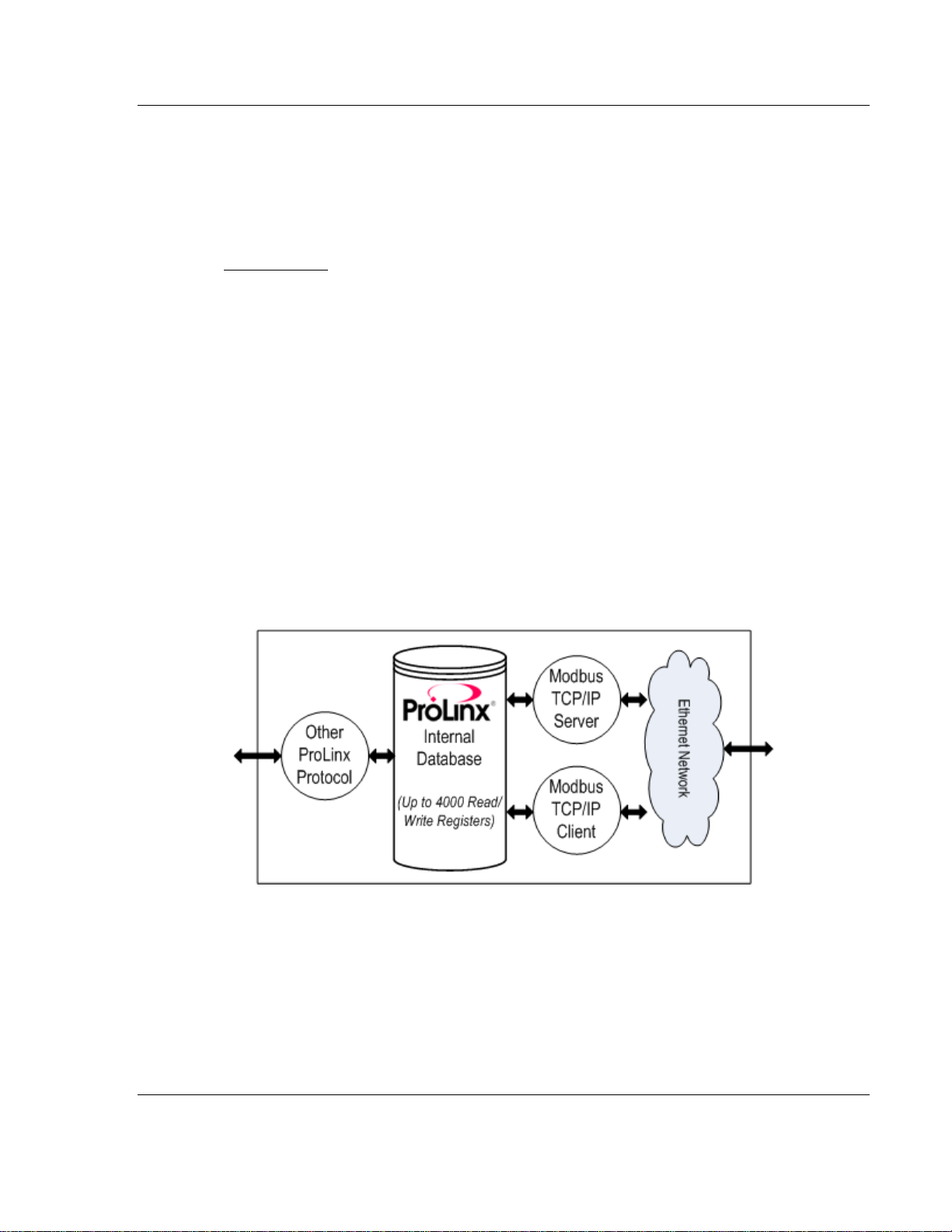
The Ethernet driver interfaces with a common internal database in the gateway.
This permits the sharing of data across many different protocols and networks.
The following illustration shows the functionality of the MNET driver.
ProSoft Technology, Inc. Page 9 of 78
September 1, 2010
Page 10

Functional Overview MNET ♦ ProLinx Gateway
DATA
LINK
DATA
LINK
Driver Manual Modbus TCP/IP Interface Module
1.1 Modbus TCP/IP (MNET) Port
The gateway supports a client connection on the TCP/IP network to interface
with processors (and other server based devices) using a user constructed
command list of up to 100 entries. The gateway’s internal database is used as
the source for write commands to the remote processors. Data collected from the
processors using read commands is placed in the gateway’s database.
Data in the gateway’s internal database is accessible for read and write
operations by any node on the network supporting the MBAP (Service Port 502)
or MNET (Service Ports 2000/2001) TCP/IP protocols. The MBAP protocol (Port
502) is a standard implementation defined by Schneider Automation and used on
their Quantum Processor. This open protocol is a modified version of the serial
Modbus protocol. The MNET protocol is an embedded Modbus protocol
message in a TCP / IP pack et. The gateway supports up to five active server
connections on Service Ports 502, five additional active server connections on
Service Port 2000, and one active client connection.
Page 10 of 78 ProSoft Technology, Inc.
September 1, 2010
Page 11

MNET ♦ ProLinx Gateway Functional Overview
Modbus TCP/IP Interface Module Driver Manual
1.2 General Specifications
10 MB Ethernet Application port
Supports Enron version of Modbus protocol for floating-point data
transactions
Configurable parameters for the client including a minimum response delay of
0 to 65535 ms and floating-point support
Supports five independent server connections for Service Port 502
Supports five independent server connections for Service Port 2000
All data mapping begins at Modbus register 400001, protocol base 0.
Error codes, network error counters, and port status data available in user
data memory
ProSoft Technology, Inc. Page 11 of 78
September 1, 2010
Page 12

Functional Overview MNET ♦ ProLinx Gateway
Driver Manual Modbus TCP/IP Interface Module
1.3 Modbus TCP/IP
ProSoft’s Modbus TCP/IP implementation uses the module’s shared internal
memory for data transfer. Sharing the memory with another protocol driver allows
the module to transfer data between Modbus TCP/IP devices and other devices
on other networks.
Configurable floating-point data movement is supported, including support for
Enron or Daniel
Modbus TCP/IP Server (Slave)
The server driver accepts incoming connections on Service Port 502 for clients
using Modbus TCP/IP MBAP messages and from clients on Service Port 2000
(or other Service Ports) for clients using Encapsulated Modbus messages..
Supports five independent server connections for Service Port 502 (MBAP)
Supports five independent server connections for Service Port 2000
(Encapsulated)
Supports a total Modbus TCP/IP data transfer capacity of up to 4000
registers or up to 64,000 bits in any combination of data types throughout the
memory database
Modbus data types overlap in the gateway’s memory database, so the same
data can be conveniently read or written as bit-level or register-level data.
®
floating-point applications.
Modbus TCP/IP Client (Master)
Actively reads data from and writes data to Modbus TCP/IP devices, using
MBAP or Encapsulated Modbus message formats
Offers one client connection with up to 100 commands to talk to multiple
severs
Status Data
Error codes, counters, and port status available
Page 12 of 78 ProSoft Technology, Inc.
September 1, 2010
Page 13
MNET ♦ ProLinx Gateway Functional Overview
Modbus TCP/IP Interface Module Driver Manual
1.4 Internal Database
Central to the functionality of the gateway is the internal database. This database
is shared between all the ports on the gateway and is used as a conduit to pass
information from one device on one network to one or more devices on another
network. This permits data from devices on one communication port to be viewed
and controlled by devices on another port.
In addition to data from the Server and Client ports, status and error information
generated by the gateway can also be mapped into the internal database.
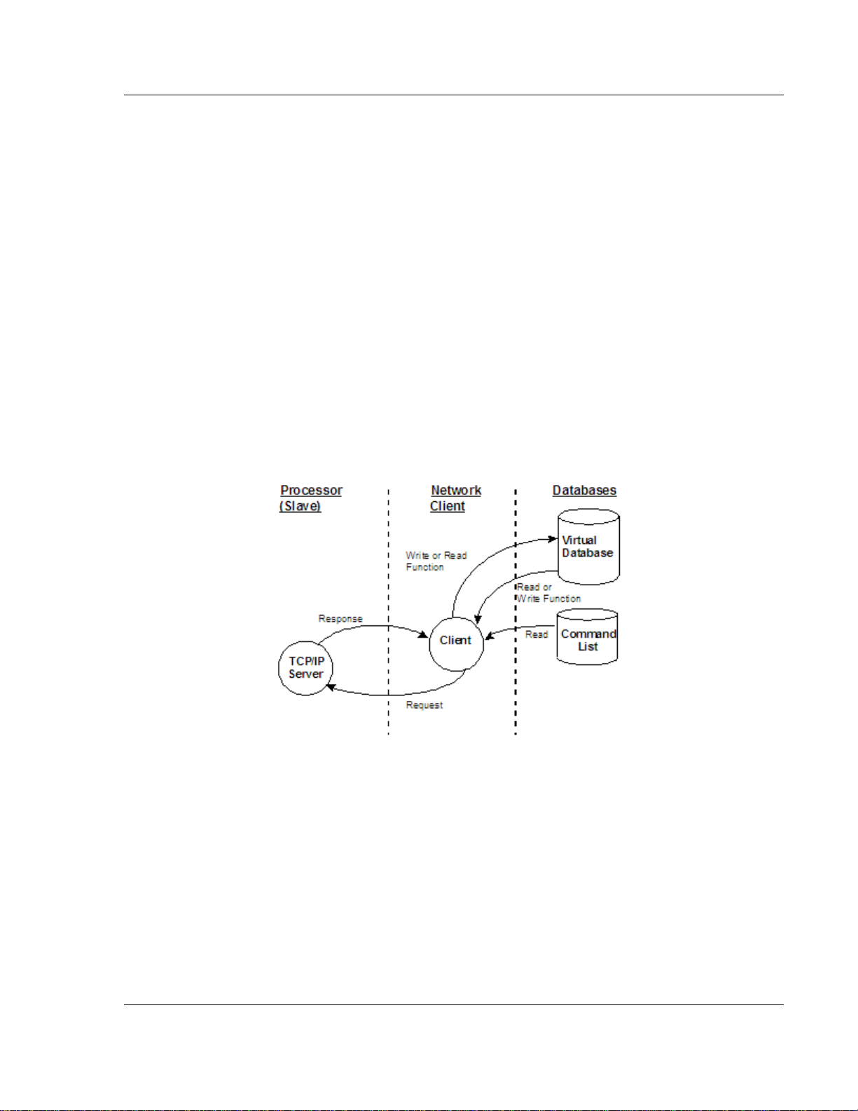
1.4.1 Modbus TCP/IP Client Access to Database
The client functionality exchanges data between MNET module's internal
database and data tables established in one or more Quantum processors or
other server based devices. The command list, defined in the user configuration,
defines what data is to be transferred between the module and each of the
servers on the network. No ladder logic is required in the processor (server) for
client functionality, except to assure that sufficient data memory exists.
The following illustration describes the flow of data between the Ethernet clients
and the internal database.
1.4.2 Modbus TCP/IP Server Access to Database
The MNET gateway provides server functionality using reserved Service Port
502 for Modbus TCP/IP MBAP messages, as well as Service Ports 2000 and
2001 to support the TCP/IP Encapsulated Modbus version of the protocol used
by several HMI manufacturers. Server support in the gateway permits client
applications (that is, HMI software, Quantum processors, and so on) to read from
and write to the gateway’s database. This document discusses the requirements
for attaching to the gateway using client applications.
ProSoft Technology, Inc. Page 13 of 78
September 1, 2010
Page 14

Functional Overview MNET ♦ ProLinx Gateway
Driver Manual Modbus TCP/IP Interface Module
The Server driver is able to support multiple concurrent connections from several
Clients. Up to five (5) Clients can simultaneously connect on Service Port 502
and five (5) more can also simultaneously connect on Service Port 2000. Service
Port 2001 is used by the MNET driver to pass Encapsulated Modbus commands
through from the Ethernet port to the gateway’s serial port (Modbus pass-through
support is available on 5201-MNET-MCM and 5202-MNET-MCM4 models only).
When configured as a Server, the internal database of the MNET gateway is
used as the source for read requests and the destination for write requests from
remote clients. Access to the database is controlled by the command type
received in the incoming message from the Client. The following table defines the
relationship of the gateway’s internal database to the addresses required in the
incoming Modbus TCP/IP requests:
Database Address Modbus Address
0 40001
1000 41001
2000 42001
3000 43001
3999 44000
The following virtual addresses are not part of the normal gateway user database
and are not valid addresses for standard data. However, these addresses may
be used for incoming commands that are requesting floating-point data. To use
addresses in this upper range requires you to set the Float Flag to Yes, the Float
Start to a database address in the range below, and the Float Offset to a
database address in the gateway user memory area shown above. Remember
that, once you do this, all data above the Float Start address must be floatingpoint data.
Database Address Modbus Address
4000 44001
5000 45001
6000 46001
7000 47001
8000 48001
9000 49001
9999 50000
The MNET gateway must be correctly configured and connected to the network
before you attempt to use it. Use a network verification program, such as the
command prompt PING instruction, to verify that the gateway can be seen on the
network. Use ProSoft Configuration Builder to confirm proper configuration of the
gateway and to transfer the configuration files to and from the gateway.
Page 14 of 78 ProSoft Technology, Inc.
September 1, 2010
Page 15

MNET ♦ ProLinx Gateway Functional Overview
Modbus TCP/IP Interface Module Driver Manual
1.4.3 Modbus Message Routing: Port 2001
When Modbus messages are sent to the module over the TCP/IP connection to
port 2001, the messages are sent (routed in the module) directly out the serial
communication port (Port 0, if it is configured as a Modbus Master. The
commands (whether a read or a write command) are immediately routed to the
slave devices on the serial port. Response messages from the slave devices are
routed to the TCP/IP network to be received by the originating host.
ProSoft Technology, Inc. Page 15 of 78
September 1, 2010
Page 16

Functional Overview MNET ♦ ProLinx Gateway
Driver Manual Modbus TCP/IP Interface Module
Page 16 of 78 ProSoft Technology, Inc.
September 1, 2010
Page 17

MNET ♦ ProLinx Gateway Modbus TCP/IP Protocol Configuration
Modbus TCP/IP Interface Module Driver Manual
2 Modbus TCP/IP Protocol Configuration
In This Chapter
Installing ProSoft Configuration Builder Software
Configure the Gateway .......................................................................... 19
[MNET Servers] ..................................................................................... 20
[MNET CLIENT 0] ................................................................................. 22
[MNET CLIENT 0 COMMANDS] ........................................................... 24
Using the CommonNet Data Map .......................................................... 31
Ethernet Configuration .......................................................................... 34
Downloading a File from PC to the Module ........................................... 35
.................................. 18
ProSoft Technology, Inc. Page 17 of 78
September 1, 2010
Page 18

Modbus TCP/IP Protocol Configuration MNET ♦ ProLinx Gateway
Driver Manual Modbus TCP/IP Interface Module
2.1 Installing ProSoft Configuration Builder Software
You must install the ProSoft Configuration Builder (PCB) software to configure
the gateway. You can always get the newest version of ProSoft Configuration
Builder from the ProSoft Technology website.
Installing ProSoft Configurati o n Builder from the ProSoft website
1 Open your web browser and navigate to http://www.prosoft-
technology.com/pcb
2 Click the DOWNLOAD HERE link to download the latest version of ProSoft
Configuration Builder.
3 Choose S
4 Save the file to your Windows Desktop, so that you can find it easily when
you have finished downloading.
5 When the download is complete, locate and open the file, and then follow the
instructions on your screen to install the program.
If you do not have access to the Internet, you can install ProSoft Configuration
Builder from the ProSoft Solutions Product CD-ROM, included in the package
with your gateway.
Installing ProSoft Configurati o n Builder from the Product CD-ROM
1 Insert the ProSoft Solutions Product CD-ROM int o the CD-ROM drive of your
PC. Wait for the startup screen to appear.
2 On the startup screen, click PRODUCT DOCUMENTATION. This action opens a
Windows Explorer file tree window.
3 Click to open the U
and files you will need to set up and configure your gateway.
4 Double-click the S
PCB_*.
software on your PC. The information represented by the "*" character in the
file name is th e PCB version number and, therefore, subject to change as
new versions of PCB are released.
AVE or SAVE FILE when prompted.
TILITIES folder. This folder contains all of the applications
ETUP CONFIGURATION TOOL folder, double-click the
EXE file and follow the instructions on your screen to install the
Note: Many of the configuration and maintenance procedures use files and other utilities on the
CD-ROM. You may wish to copy the files from the Utilities folder on the CD-ROM to a convenient
location on your hard drive.
2.1.1 Using the Online Help
Most of the information needed to help you use ProSoft Configuration Builder is
provided in a Help System that is always available whenever you are running
ProSoft Configuration Builder. The Help System does not require an Internet
connection.
To view the help pages, start ProSoft Configuration Builder, open the H
menu, and then choose CONTENTS.
Page 18 of 78 ProSoft Technology, Inc.
September 1, 2010
ELP
Page 19

MNET ♦ ProLinx Gateway Modbus TCP/IP Protocol Configuration
Modbus TCP/IP Interface Module Driver Manual
2.2 Configure the Gateway
2.2.1 Configuring Module Parameters
1 Click on the [+] sig n next to the gateway icon to expand gateway information.
2 Click on the
[+] sign next to any icon to view gateway information and
configuration options.
3 Double-click any
icon to open an Edit dialog box.
4 To edit a parameter, select the parameter in the left pane and make your
changes in the right pane.
5 Click OK
to save your changes.
2.2.2 Printing a Configuration File
1 Select the gateway icon, and then click the right mouse button to open a
shortcut menu.
2 On the
View Configuration window.
3 On the View Configuration window, open the F
This action opens the Print dialog box.
4 On the Print dialog box, choose the printer to use from the drop-down list,
select printing options, and then click OK.
shortcut menu, choose VIEW CONFIGURATION. This action opens the
ILE menu, and choose PRINT.
ProSoft Technology, Inc. Page 19 of 78
September 1, 2010
Page 20
Modbus TCP/IP Protocol Configuration MNET ♦ ProLinx Gateway
Driver Manual Modbus TCP/IP Interface Module
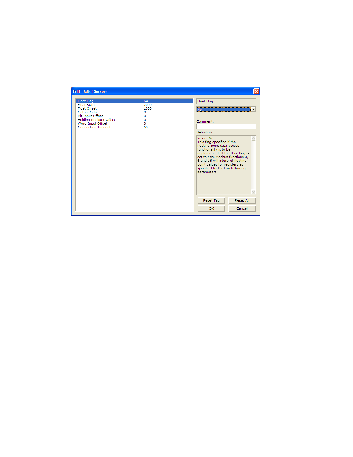
2.3 [MNET Servers]
This section contains database offset information used by the servers when
accessed by external clients. These offsets can be utilized to segment the
database by data type.
2.3.1 Float Flag
Yes or No
This flag specifies if the floating-point data access functionality is to be
implemented. If the float flag is set to Yes, Modbus functions 3, 6, a nd 16 will
interpret floating-point values for registers as specified by the two following
parameters.
2.3.2 Float Start
0 to 32767
This parameter defines the first register of floating-point data. All requests with
register values greater-than or equal to this value will be considered floating-point
data requests. This parameter is only used if the Float Flag is enabled. For
example, if a value of 7000 is entered, all requests for registers 7000 and above
will be considered as floating-point data.
2.3.3 Float Offset
0 to 4999
This parameter defines the start register for floating-point data in the internal
database. This parameter is used only if the Float Flag is enabled. For example,
if the Float Offset value is set to 3000 and the float start parameter is set to 7000,
data requests for register 7000 will use the internal Modbus register 3000.
Page 20 of 78 ProSoft Technology, Inc.
September 1, 2010
Page 21

MNET ♦ ProLinx Gateway Modbus TCP/IP Protocol Configuration
Modbus TCP/IP Interface Module Driver Manual
2.3.4 Output Offset
0 TO 3999
When the port is configured as a slave, this parameter specifies the internal
database address to use as the zero address or starting point for binary output
Coil data. Coil data is read by Modbus Function Code 1 commands (Read Coils)
and written by Function Codes 5 (Force Single Coil) or Function Code 15 (Force
Multiple Coils). For example, if this parameter is set to 50 and a Function Code 1
command is received requesting Coil address 0 (virtual Modbus Coil address
00001 or 000001), the data returned in the response will be the value at register
50, bit 0 in the gateway's database.
2.3.5 Bit Input Offset
0 to 3999
This parameter specifies the offset address in the internal Modbus database for
network requests for Modbus function 2 commands. For example, if the value is
set to 150, an address request of 0 will return the value at register 150 in the
database.
2.3.6 Holding Register Offset
0 to 4999
This parameter specifies the offset address in the internal Modbus database to
with network requests for Modbus functions 3, 6, or 16 commands. For example,
if the value is set to 50, an address request of 0 will return the value at register
50 in the database.
2.3.7 Word Input Offset
0 to 3999
This parameter specifies the offset address in the internal Modbus database for
network requests for Modbus function 4 commands. For example, if the value is
set to 150, an address request of 0 will return the value at register 150 in the
database.
2.3.8 Connection Timeout
0 to 1200 seconds.
This is the number of seconds the Server will wait to receive new data. If the
Server does not receive any new data during this time, it will close the
connection.
ProSoft Technology, Inc. Page 21 of 78
September 1, 2010
Page 22
Modbus TCP/IP Protocol Configuration MNET ♦ ProLinx Gateway
Driver Manual Modbus TCP/IP Interface Module
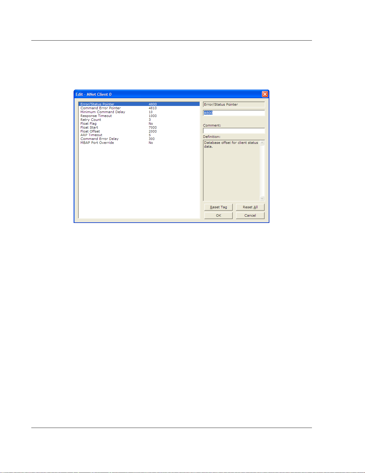
2.4 [MNET CLIENT 0]
The [MNET CLIENT 0] section of the CFG file specifies the parameters for the
client to be emulated on the gateway. The command list for the client is entered
in a separate section.
2.4.1 Minimum Command Delay
0 to 32767
This parameter specifies the number of milliseconds to wait between the initial
issuance of a command. This parameter can be used to delay all commands sent
to slaves to avoid "flooding" commands on the network. This parameter does not
affect retries of a command as they will be issued when failure is recognized.
2.4.2 Response Timeout
0 to 65535 milliseconds
This is the time in milliseconds that a Client will wait before re-transmitting a
command if no response is received from the addressed server. The value to use
depends upon the type of communication network used, and the expected
response time of the slowest device on the network.
2.4.3 Retry Count
0 to 10
This parameter specifies the number of times a command will be retried if it fails.
Page 22 of 78 ProSoft Technology, Inc.
September 1, 2010
Page 23

MNET ♦ ProLinx Gateway Modbus TCP/IP Protocol Configuration
Modbus TCP/IP Interface Module Driver Manual
2.4.4 Float Flag
Yes or No
This flag specifies if the floating-point data access functionality is to be
implemented. If the float flag is set to Yes, Modbus functions 3, 6, and 16 will
interpret floating-point values for registers as specified by the two following
parameters.
2.4.5 Float Start
0 to 32767
This parameter defines the first register of floating-point data. All requests with
register values greater-than or equal to this value will be considered floating-point
data requests. This parameter is only used if the Float Flag is enabled. For
example, if a value of 7000 is entered, all requests for registers 7000 and above
will be considered as floating-point data.
2.4.6 Float Offset
0 TO 3998
This parameter defines the starting register for floating-point data in the internal
gateway database. This parameter is used only if the Float Flag is set to Y For example, if the Float Offset value is set to 3000 and the Float Start parameter
is set to 7000, the data returned as floating-point data for register 47001 (or
407001) will actually come from internal gateway registers 3000 and 3001. If the
requested address was 47002 (407002), the data will be returned from internal
registers 3002 and 3003. If the requested address was 47101 (407101), the data
will be returned from internal registers 3200 and 3201; and so on.
ES.
2.4.7 ARP Timeout
1 to 60
This parameter specifies the number of seconds to wait for an ARP reply after a
request is issued.
2.4.8 Command Error Delay
0 to 300
This parameter specifies the number of 100 millisecond intervals to turn off a
command in the error list after an error is recognized for the command. If this
parameter is set to 0, there will be no delay.
ProSoft Technology, Inc. Page 23 of 78
September 1, 2010
Page 24
Modbus TCP/IP Protocol Configuration MNET ♦ ProLinx Gateway
Driver Manual Modbus TCP/IP Interface Module
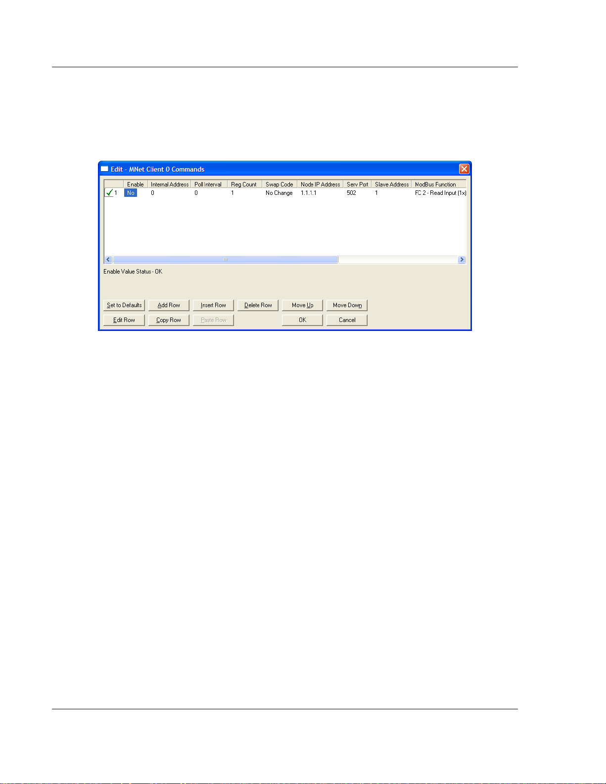
2.5 [MNET CLIENT 0 COMMANDS]
The [MNET CLIENT 0 COMMANDS] section defines the Modbus TCP/IP
commands to be issued from the gateway to server devices on the network.
These commands can be used for data collection and/or control of devices on
the TCP/IP network.
The command list is formatted differently than the other sections of the
configuration file. Commands are present in a block between the labels START
and END. These labels inform the program where the list resides. The gateway's
program will parse all commands after the START label until it reaches the END
label or until the command count entered for the port is reached.
2.5.1 Command List Overview
In order to interface the ProLinx module with Modbus TCP/IP Server devices,
you must construct a command list. The commands in the list specify the Server
device to be addressed, the function to be performed (read or write), the data
area in the device to interface with and the registers in the internal database to
be associated with the device data. The Client command list supports up to 16
commands.
The command list is processed from top (command #0) to bottom. A poll interval
parameter is associated with each command to specify a minimum delay time in
tenths of a second between the issuance of a command. If the user specifies a
value of 10 for the parameter, the command will be executed no more frequently
than every 1 second.
Write commands have a special feature, as they can be set to execute only if the
data in the write command changes. If the register data values in the command
have not changed since the command was last issued, the command will not be
executed. If the data in the command has changed since the command was last
issued, the command will be executed. Use of this feature can lighten the load on
the network. In order to implement this feature, set the enable code for the
command to a value of 2.
Page 24 of 78 ProSoft Technology, Inc.
September 1, 2010
Page 25

MNET ♦ ProLinx Gateway Modbus TCP/IP Protocol Configuration
Modbus TCP/IP Interface Module Driver Manual
2.5.2 Commands Supported by the Module
The format of each command in the list depends on the Modbus Function Code
being executed.
The following table lists the functions supported by the module.
Function Code Definition Supported in Client Supported in Server
1 Read Coil Status X X
2 Read Input Status X X
3 Read Holding Registers X X
4 Read Input Registers X X
5 Set Single Coil X X
6 Single Register Write X X
7 Read Exception Status X
8 Diagnostics X
15 Multiple Coil Write X X
16 Multiple Register Write X X
22 Mask Write 4X X
23 Read/Write X
Each command list record has the same general format. The first part of the
record contains the information relating to the communication module and the
second part contains information required to interface to the Modbus TCP/IP
Server device.
2.5.3 Command Entry Formats
The following table shows the structure of the configuration data necessary for
1 2 3 4 5 6 7 8 9 10
Enable
Code
Code Register
Code Register
Code Register 1/10th Seconds Word
Code Register 1/10th Seconds Word
Code 1 bit 1/10th Seconds Bit
Code 1 bit 1/10th Seconds Word
Code Register
Code Register 1/10th Seconds Word
each of the supported commands.
Internal
Address
(bit)
(bit)
(bit)
Poll Interval
Time
1/10th Seconds Bit
1/10th Seconds Bit
1/10th Seconds Bit
Count Swap
Count
Count
Count
Count
Count
Count
Count
Count
Code
0 IP Address Port # Address Read Coil (0x) Register
0 IP Address Port # Address Read Input (1x) Register
Code IP Address Port # Address Read Holding
0 IP Address Port # Address Read Input Registers
0 IP Address Port # Address Force (Write) Single
0 IP Address Port # Address Preset (Write) Single
0 IP Address Port # Address Force (Write) Multiple
0 IP Address Port # Address Preset (Write) Multiple
IP Address Serv
Port
Slave
Node
Function Code Device Modbus
Address
Register
Registers (4x)
Register
(3x)
Register
Coil (0x)
Register
Register (4x)
Register
Coil (0x)
Register
Register (4x)
ProSoft Technology, Inc. Page 25 of 78
September 1, 2010
Page 26

Modbus TCP/IP Protocol Configuration MNET ♦ ProLinx Gateway
Driver Manual Modbus TCP/IP Interface Module
The first part of the record is the gateway Information, which relates to the
ProLinx gateway and the second part contains information required to interface
to the Server device.
Command list example:
2.5.4 Enable
YES, NO, or CONDITIONAL
This field defines whether the command is to be executed and under what
conditions.
Value Description
0 The command is disabled and will not be executed in the normal polling sequence.
1 The command is executed each scan of the command list if the Poll Interval Time is
set to zero. If the Poll Interval time is set, the command will be executed, when the
interval timer expires.
2 The command will execute only if the internal data associated with the command
changes. This value is valid only for write commands.
Page 26 of 78 ProSoft Technology, Inc.
September 1, 2010
Page 27

MNET ♦ ProLinx Gateway Modbus TCP/IP Protocol Configuration
Modbus TCP/IP Interface Module Driver Manual
2.5.5 Internal Address
0 to 4999 (for word-level addressing)
or
0 to 65535 (for bit-level addressing)
This field specifies the database address in the gateway's internal database to
use as the destination for data brought in by a read command or as the source
for data to be sent out by a write command. The database address is interpreted
as a bit address or a 16-bit word (register) address, depending on the Modbus
Function Code used in the command.
For Modbus functions 1, 2, 5, and 15, this parameter is interpreted as a bit-
level address.
For Modbus functions 3, 4, 6, and 16, this parameter is interpreted as a word-
or register-level address.
2.5.6 Reg Count
Regs: 1 to 125
Coils: 1 to 800
This parameter specifies the number of 16-bit registers or binary bits to be
transferred by the command.
Functions 5 and 6 ignore this field as they apply only to a single data point.
For functions 1, 2, and 15, this parameter sets the number of bits (inputs or
coils) to be transferred by the command.
For functions 3, 4, and 16, this parameter sets the number of registers to be
transferred by the command.
ProSoft Technology, Inc. Page 27 of 78
September 1, 2010
Page 28

Modbus TCP/IP Protocol Configuration MNET ♦ ProLinx Gateway
Driver Manual Modbus TCP/IP Interface Module
2.5.7 Swap Code
NONE
S
WAP WORDS
S
WAP WORDS & BYTES
WAP BYTES
S
This parameter defines if and how the order of bytes in data received or sent is to be rearranged. This option exists to allow for the fact that different manufacturers store and transmit multi-byte data in different combinations that do other manufacturers. This parameter is helpful when dealing with floating-point or other multi-byte values, as there is no one standard method of storing these data types. This parameter can be set to rearrange the byte order of data received or sent into order more useful or convenient for other applications. The following table defines the valid Swap Code values and the effect they have on the byteorder of the data.
Swap Code Description
None No Change is made in the byte ordering (1234 = 1234)
Swap Words The words are swapped (1234=3412)
Swap Words & Bytes The words are swapped then the bytes in each word are swapped
(1234=4321)
Swap Bytes The bytes in each word are swapped (1234=2143)
These swap operations affect 4-byte (or 2-word) groups of data. Therefore, data
swapping using these Swap Codes should be done only when using an even
number of words, such as when 32-bit integer or floating-point data is involved.
2.5.8 Node IP Address
xxx.xxx.xxx.xxx
The IP address of the device being addressed by the command.
2.5.9 Service Port
502 or other supported ports on server
Use a value of 502 when addressing Modbus TCP/IP servers that are compatible
with the Schneider Electric MBAP specifications (this will be most devices). If a
server implementation supports another service port, enter the value here.
Page 28 of 78 ProSoft Technology, Inc.
September 1, 2010
Page 29

MNET ♦ ProLinx Gateway Modbus TCP/IP Protocol Configuration
Modbus TCP/IP Interface Module Driver Manual
2.5.10 Slave Address
0 - Broadcast to all nodes
1 to 255
Use this parameter to specify the slave address of a remote Modbus Serial
device through a Modbus Ethernet to Serial converter.
Note: Use the Node IP Address parameter (page 28) to address commands to a remote Modbus
TCP/IP device.
Note: Most Modbus devices accept an address in the range of only 1 to 247, so check with slave
device manufacturer to see if a particular slave can use addresses 248 to 255.
If the value is set to zero, the command will be a broadcast message on the network. The Modbus
protocol permits broadcast commands for write operations. Do not use node address 0 for read
operations.
2.5.11 Modbus Function
1, 2, 3, 4, 5, 6, 15, or 16
This parameter specifies the Modbus Function Code to be executed by the
command. These function codes are defined in the Modbus protocol. The
following table lists the purpose of each function supported by the module. More
information on the protocol is available from www.modbus.org.
Modbus Function Code Description
1 Read Coil Status
2 Read Input Status
3 Read Holding Registers
4 Read Input Registers
5 Force (Write) Single Coil
6 Preset (Write) Single Register
15 Force Multiple Coils
16 Preset Multiple Registers
ProSoft Technology, Inc. Page 29 of 78
September 1, 2010
Page 30

Modbus TCP/IP Protocol Configuration MNET ♦ ProLinx Gateway
Driver Manual Modbus TCP/IP Interface Module
2.5.12 MB Address in Device
This parameter specifies the starting Modbus register or bit address in the slave
to be used by the command. Refer to the documentation of each Modbus slave
device for the register and bit address assignments valid for that device.
The Modbus Function Code determines whether the address will be a register- or
bit- level OFFSET address into a given data type range. The offset will be the
target data address in the slave minus the base address for that data type. Base
addresses for the different data types are:
00001 or 000001 (0x0001) for bit-level Coil data (Function Codes 1, 5, and
15).
10001 or 100001 (1x0001) for bit-level Input Status data (Function Code 2)
30001 or 300001 (3x0001) for Input Register data (Function Code 4)
40001 or 400001 (4x0001) for Holding Register data (Function Codes 3, 6,
and 16).
Address calculation examples:
For bit-level Coil commands (FC 1, 5, or 15) to read or write a Coil 0X
address 00001, specify a value of 0 (00001 - 00001 = 0).
For Coil address 00115, specify 114
(00115 - 00001 = 114)
For register read or write commands (FC 3, 6, or 16) 4X range, for 40001,
specify a value of 0
(40001 - 40001 = 0).
For 01101, 11101, 31101 or 41101, specify a value of 1100.
(01101 - 00001 = 1100)
(11101 -10001 = 1100)
(31101 - 30001 = 1100)
(41101 - 40001 = 1100)
Note: If the documentation for a particular Modbus slave device lists data addresses in
hexadecimal (base16) notation, you will need to convert the hexadecimal value to a decimal value
to enter in this parameter. In such cases, it is not usually necessary to subtract 1 from the
converted decimal number, as this addressing scheme typically uses the exact offset address
expressed as a hexadecimal number.
Page 30 of 78 ProSoft Technology, Inc.
September 1, 2010
Page 31

MNET ♦ ProLinx Gateway Modbus TCP/IP Protocol Configuration
Modbus TCP/IP Interface Module Driver Manual
2.6 Using the CommonNet Data Map
The Data Map section allows you to copy data between areas in the gateway's
internal database.
You can copy a maximum of 100 registers per Data Map command, and you can
configure a maximum of 200 separate copy commands.
You can copy data from the error or status tables in upper memory to internal
database registers in the User Data memory area.
You can rearrange the byte and/or word order during the copy process. For
example, by rearranging byte or word order, you can convert floating-point values
to the correct format for a different protocol.
You can also use the Data Map to condense widely dispersed data into one
contiguous data block, making it easier to access.
ProSoft Technology, Inc. Page 31 of 78
September 1, 2010
Page 32

Modbus TCP/IP Protocol Configuration MNET ♦ ProLinx Gateway
Driver Manual Modbus TCP/IP Interface Module
2.6.1 From Address
0 to highest Status Data address
This field specifies the beginning internal database register address for the copy
operation. This address can be any valid address in the User Data Area or the
Status Data Area of the gateway.
2.6.2 To Address
0 to 3999
This parameter specifies the beginning destination register address for the copy
operation. This address must always be within the User Data registers area.
Take care to specify a destination address that will not overwrite data that has
been stored in memory by one of the communication protocols running on the
gateway.
2.6.3 Register Count
1 to 100
This parameter specifies the number of registers to copy.
2.6.4 Swap Code
NO CHANGE, WORD SWAP, WORD AND BYTE SWAP, BYTE SWAP
You may need to swap the order of the bytes in the registers during the copy
process in order to change the alignment of bytes between dissimilar protocols.
This parameter is helpful when dealing with floating-point or other multi-register
values, as there is no standard method of storage of these data types in slave
devices.
The following table defines the values and their associated operations:
Swap Code Description
No Swap No change is made in the byte ordering (1234 = 1234)
Word Swap The words are swapped (1234=3412)
Word and
Byte Swap
Bytes The bytes in each word are swapped (1234=2143)
The words are swapped, then the bytes in each word are swapped (1234=4321)
Page 32 of 78 ProSoft Technology, Inc.
September 1, 2010
Page 33

MNET ♦ ProLinx Gateway Modbus TCP/IP Protocol Configuration
Modbus TCP/IP Interface Module Driver Manual
2.6.5 Delay Preset
This parameter sets an interval for each Data Map copy operation. The value you put for the Delay Preset is not a fixed amount of time. It is the number of firmware scans that must transpire between copy operations.
The firmware scan cycle can take a variable amount of time, depending on the
level of activity of the protocol drivers running on the ProLinx gateway and the
level of activity on the gateway's communication ports. Each firmware scan can
take from 1 to several milliseconds to complete. Therefore, Data Map copy
operations cannot be expected to happen at regular intervals.
If multiple copy operations (several rows in the Data map section) happen too
frequently or all happen in the same update interval, they could delay the process
scan of the gateway protocols, which could result in slow data updates or missed
data on communication ports. To avoid these potential problems, you should set
the Delay Preset to different values for each row in the Data Map section and set
them to higher, rather than lower, numbers.
For example, Delay Preset values below 1000 could begin to cause a noticeable
delay in data updates through the communication ports. And you should not set
all Delay Presets to the same value. Instead, use different values for each row in
the Data Map such as 1000, 1001, and 1002 or any other different Delay Preset
values you like. This will prevent the copies from happening concurrently and
prevent possible process scan delays.
ProSoft Technology, Inc. Page 33 of 78
September 1, 2010
Page 34

Modbus TCP/IP Protocol Configuration MNET ♦ ProLinx Gateway
Driver Manual Modbus TCP/IP Interface Module
2.7 Ethernet Configuration
Use this procedure to configure the Ethernet settings for your module. You must
assign an IP address, subnet mask and gateway address. After you complete
this step, you can connect to the module with an Ethernet cable.
1 Determine the network settings for your module, with the help of your network
administrator if necessary. You will need the following information:
o IP address (fixed IP required) _____ . _____ . _____ . _____
o Subnet mask _____ . _____ . _____ . _____
o Gateway address _____ . _____ . _____ . _____
Note: The gateway address is optional, and is not required for networks that do not use a default
gateway.
2 Double-click the E
dialog box.
THERNET CONFIGURATION icon. This action opens the Edit
3 Edit the values for my_ip, netmask (subnet mask) and gateway (default
gateway).
4 When you are finished editing, click OK
the ProSoft Configuration Builder window.
to save your changes and return to
Page 34 of 78 ProSoft Technology, Inc.
September 1, 2010
Page 35

MNET ♦ ProLinx Gateway Modbus TCP/IP Protocol Configuration
Modbus TCP/IP Interface Module Driver Manual
2.8 Downloading a File from PC to the Module
1 Verify that your PC is connected to the gateway with a null-modem serial
cable connected to the serial port on your PC and the serial port on the
gateway
2 Open the P
3 On the M
scans for communication ports on your PC. When the scan is complete, the
Download
ROJECT menu, and then choose MODULE.
ODULE menu, choose DOWNLOAD. Wait while ProSoft Configuration
dialog box opens.
4 Select the
5 Click the D
PORT to use for the download.
OWNLOAD button.
Note: If you change the IP Address, you must cycle power to the gateway for the change to take
effect.
ProSoft Technology, Inc. Page 35 of 78
September 1, 2010
Page 36

Modbus TCP/IP Protocol Configuration MNET ♦ ProLinx Gateway
Driver Manual Modbus TCP/IP Interface Module
Page 36 of 78 ProSoft Technology, Inc.
September 1, 2010
Page 37

MNET ♦ ProLinx Gateway Diagnostics and Troubleshooting
Modbus TCP/IP Interface Module Driver Manual
3 Diagnostics an d Troubleshootin g
In This Chapter
Debug Port Requirements
LED Indicators ....................................................................................... 49
MNET Error and Status Data ................................................................. 50
..................................................................... 38
There are two ways to troubleshoot ProLinx Gateways:
Using the LEDs located on the front of the gateway
Using the Debug port that provides a view into the gateway's internal
database.
ProSoft Technology, Inc. Page 37 of 78
September 1, 2010
Page 38

Diagnostics and Troubleshooting MNET ♦ ProLinx Gateway
Driver Manual Modbus TCP/IP Interface Module
3.1 Debug Port Requirements
In order to use the Debug capabilities of any ProLinx Module you will need the
following:
A PC running ProSoft Configuration Builder or HyperTerminal software
A Null Modem cable
A Mini-DIN to DB-9M connector
Configuration and executable files described earlier
3.1.1 Using ProSoft Configuration Builder (PCB) for Diagnostics
The Configuration and Debug menu for this gateway is arranged as a tree
structure, with the Main menu at the top of the tree, and one or more submenus
for each menu command. The first menu you see when you connect to the
gateway is the
Because this is a text-based menu system, you enter commands by typing the
[command letter] from your computer keyboard in the Diagnostic window in
ProSoft Configuration Builder (PCB). The gateway does not respond to mouse
movements or clicks. The command executes as soon as you press the
[COMMAND LETTER] — you do not need to press [ENTER]. When you type a
[COMMAND LETTER], a new screen will be displayed in your terminal application.
Main menu.
Required Hardware
You can connect directly from your computer’s serial port to the serial port on the
gateway to view configuration information, perform maintenance, and send or
receive configuration files.
ProSoft Technology recommends the following minimum hardware to connect
your computer to the gateway:
80486 based processor (Pentium preferred)
1 megabyte of memory
At least one UART hardware-based s er ial communications port available.
USB-based virtual UART systems (USB to serial port adapters) often do not
function reliably, especially during binary file transfers, such as when
uploading/downloading configuration files or gateway firmware upgrades.
Using the Diagnostic Window in ProSoft Configuration Builder
To connect to the gateway’s Configuration/Debug serial port
1 Start PCB, and then select the gateway to test. Click the right mouse button
to open a shortcut
menu.
Page 38 of 78 ProSoft Technology, Inc.
September 1, 2010
Page 39

MNET ♦ ProLinx Gateway Diagnostics and Troubleshooting
Modbus TCP/IP Interface Module Driver Manual
2 On the shortcut menu, choose DIAGNOSTICS.
This action opens the Diagnostics
3 Press [?]
to open the Main menu.
dialog box.
If there is no response from the gateway, follow these steps:
ProSoft Technology, Inc. Page 39 of 78
September 1, 2010
Page 40

Diagnostics and Troubleshooting MNET ♦ ProLinx Gateway
Driver Manual Modbus TCP/IP Interface Module
1 Click to configure the connection. On the Connection Setup dialog box, select
a valid com port or other connection type supported by the gateway.
2 Verify that the null modem cable is connected properly between your
computer’s serial port and the gateway. A regular serial cable will not work.
3 On computers with more than one serial port, verify that your communication
program is connected to the same port that is connected to the gateway.
If you are still not able to establish a connection, contact ProSoft Technology for
assistance.
Page 40 of 78 ProSoft Technology, Inc.
September 1, 2010
Page 41

MNET ♦ ProLinx Gateway Diagnostics and Troubleshooting
Modbus TCP/IP Interface Module Driver Manual
Navigation
All of the submenus for this gateway contain commands to redisplay the menu or
return to the previous menu. You can always return from a submenu to the next
higher menu by pressing [M]
on your keyboard.
The organization of the menu structure is represented in simplified form in the
following illustra tion:
The remainder of this section shows the menus available for this gateway, and
briefly discusses the commands available to you.
Keystrokes
The keyboard commands on these menus are usually not case sensitive. You
can enter most commands in lowercase or uppercase letters.
The menus use a few special characters (?,
as shown. Some of these characters will require you to use the SHIFT,
ALT
keys to enter them correctly. For example, on US English keyboards, enter
the ?
command as SHIFT and /.
Also, take care to distinguish the different uses for uppercase letter "eye" (I),
-, +, @) that must be entered exactly
CTRL, or
lowercase letter "el" (L), and the number one (1). Likewise, uppercase letter "oh"
(O)
and the number zero (0) are not interchangeable. Although these characters
look alike on the screen, they perform different actions on the gateway and may
not be used interchangeably.
3.1.2 Main Menu
When you first connect to the module from your computer, your terminal screen
will be blank. To activate the main menu, press the [?]
keyboard. If the module is connected properly, the main menu will appear on
your terminal screen.
Caution: Some of the commands available to you from this menu are designed for advanced
debugging and system testing only, and can cause the gateway to stop communicating with the
processor or with other devices, resulting in potential data loss or other failures. Only use these
commands if you are specifically directed to do so by ProSoft Technology Technical Support staff.
Some of these command keys are not listed on the menu, but are active nevertheless. Please be
careful when pressing keys so that you do not accidentally execute an unwanted command.
ProSoft Technology, Inc. Page 41 of 78
September 1, 2010
key on your computer’s
Page 42

Diagnostics and Troubleshooting MNET ♦ ProLinx Gateway
Driver Manual Modbus TCP/IP Interface Module
Opening the Database View Menu
Press [D] to open the Database View menu.
Use this menu command to view the current contents of the gateway’s database.
For more information about this submenu, see Database View Menu (page 43).
Viewing Module Configuration
Press [C] to view the Module Configuration screen.
Use this command to display the current configuration and statistics for the
gateway.
Viewing Version Information
Press [V] to view version information for the gateway.
Use this command to view the current version of the software for the gateway, as
well as other important values. You may be asked to provide this information
when calling for technical support on the product.
Values at the bottom of the display are important in determining gateway
operation. The Program Scan Counter value is incremented each time a
gateway’s program cycle is complete.
Tip: Repeat this command at one-second intervals to determine the frequency of program
execution.
Viewing Client Configuration
Press [B] to view configuration information for the client.
Opening the Network Menu
Press [@] to open the Network menu.
The Network menu allows you to send, receive and view the WATTCP.CFG file
that contains the IP, gateway and other network specification information. For
more information about this submenu, see Network Menu (page 47).
Warm Booting the Module
Press [W] from the Main menu to warm boot (restart) the gateway.
This command will cause the program to exit and reload, refreshing configuration
parameters that must be set on program initialization. Only use this command if
you must force the gateway to reboot.
Exiting the Program
Press [ESC] to restart the gateway and force all drivers to be loaded. The
gateway will use the configuration stored in the gateway's Flash memory to
configure the gateway.
Page 42 of 78 ProSoft Technology, Inc.
September 1, 2010
Page 43
MNET ♦ ProLinx Gateway Diagnostics and Troubleshooting
Modbus TCP/IP Interface Module Driver Manual
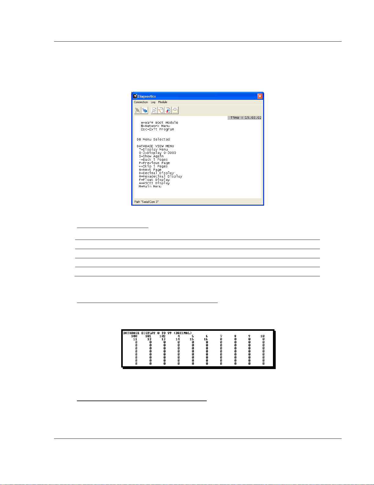
3.1.3 Database View Menu
Press [D] from the Main menu to open the Database View menu. Use this menu
command to view the current contents of the gateway database. Press [?]
view a list of commands available on this menu.
to
Viewing Register Pages
To view sets of register pages, use the keys described below:
Command Description
[0]
[1]
[2]
Display registers 0 to 99
Display registers 1000 to 1099
Display registers 2000 to 2099
And so on. The total number of register pages available to view depends on your
gateway’s configuration.
Displaying the Current Page of Registers Again
Press [S]
from the Database View menu to show the current page of registers
again.
This screen displays the current page of 100 registers in the database.
Moving Back Through 5 Pages of Registers
Press [-] from the Database View menu to skip five pages back in the database
to see the 100 registers of data starting 500 registers before the currently
displayed page.
ProSoft Technology, Inc. Page 43 of 78
September 1, 2010
Page 44

Diagnostics and Troubleshooting MNET ♦ ProLinx Gateway
Driver Manual Modbus TCP/IP Interface Module
Moving Forward Through 5 Pages of Registers
Press [+] from the Database View menu to skip five pages ahead in the database
to see the 100 registers of data starting 500 registers after the currently displayed
page.
Viewing the Previous 100 Registers of Data
Press [P] from the Database View menu to display the previous 100 registers of
data.
Viewing the Next 100 Registers of Data Press [N] from the Database View menu to display the next 100 registers of data.
Viewing Data in Decimal Format
Press [D] from t he Database View menu to display the data on the current page
in decimal format.
Viewing Data in Hexadecimal Format
Press [H] from the Database View menu to display the data on the current page
in hexadecimal format.
Viewing Data in Floating-Point Format
Press [F] from the Database View menu to display the data on the current page
in floating-point format. The program assumes that the values are aligned on
even register boundaries. If floating-point values are not aligned as such, they
are not displayed properly.
Viewing Data in ASCII (Text) Format
Press [A] from the Database View menu to display the data on the current page
in ASCII format. This is useful for regions of the database that contain ASCII
data.
Returning to the Main Menu
Press [M] to return to the Main menu.
Page 44 of 78 ProSoft Technology, Inc.
September 1, 2010
Page 45

MNET ♦ ProLinx Gateway Diagnostics and Troubleshooting
Modbus TCP/IP Interface Module Driver Manual
3.1.4 Master Command Error List Menu
Use this menu to view the command error list for the module. Press [?] to view a
list of commands available on this menu.
Redisplaying the Current Page
Press [S]
Viewing the Previous 20 Commands
Press [-] to display data for the previous 20 commands.
Viewing the Previous Page of Commands
Press [P] to display the previous page of commands.
Viewing the Next 20 Commands
Press [+] to display data for the next 20 commands.
Viewing the Next Page of Commands
Press [N] to display the next page of commands.
to display the current page of data.
Returning to the Main Menu
Press [M] to return to the Main menu.
ProSoft Technology, Inc. Page 45 of 78
September 1, 2010
Page 46

Diagnostics and Troubleshooting MNET ♦ ProLinx Gateway
Driver Manual Modbus TCP/IP Interface Module
3.1.5 Master Command List Menu
Use this menu to view the command list for the module. Press [?] to view a list of
commands available on this menu.
Redisplaying the Current Page
Press [S] to display the current page of data.
Viewing the Previous 50 Commands
Press [-] to view the previous 50 commands.
Viewing the Previous Page of Commands
Press [P] to display the previous page of commands.
Viewing the Next 50 Commands
Press [+] to view the next 50 commands from the master command list.
Viewing the Next Page of Commands
Press [N] to display the next page of commands.
Returning to the Main Menu
Press [M] to return to the Main menu.
Page 46 of 78 ProSoft Technology, Inc.
September 1, 2010
Page 47
MNET ♦ ProLinx Gateway Diagnostics and Troubleshooting
Modbus TCP/IP Interface Module Driver Manual
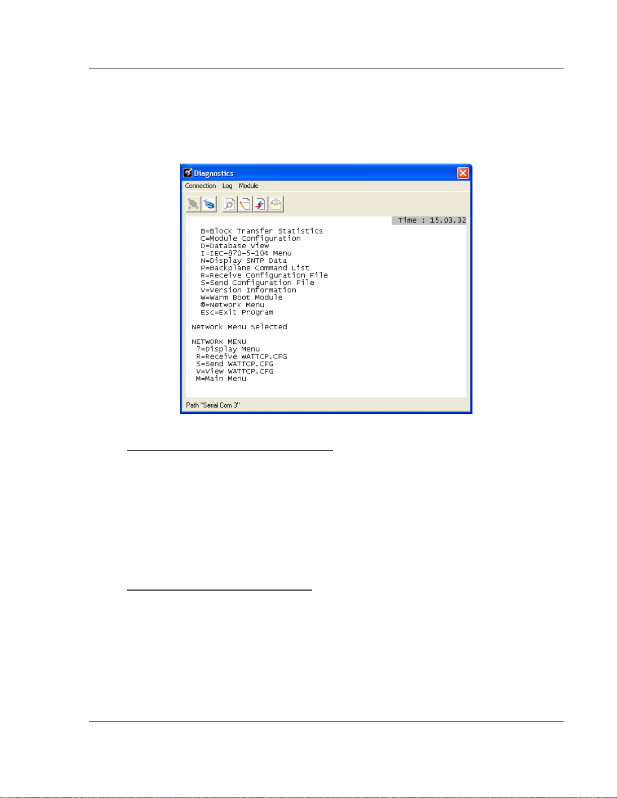
3.1.6 Network Menu
From the IEC-870-5-104 Server menu press [@] to display the IEC-870-5-104
Network menu screen. The Network menu allows you to send, receive, and view
the WATTCP.CFG file that contains the IP and gateway addresses, and other
network information.
Transferring WATTCP.CFG to the module
Use this command if you are using HyperTerminal to communicate with the
module, instead of using ProSoft Configuration Builder (the preferred method).
Press [R] to transfer a new WATTCP.CFG file from the PC to the module. Use
this command to change the network configuration for the module (for example,
the module’s IP address).
Press [Y]
to confirm the file transfer, and then open the Transfer menu in
HyperTerminal. On the Transfer menu, choose Send File, and then choose
Ymodem as the file transfer protocol.
Transferring WATTCP.CFG to the PC
Use this command if you are using HyperTerminal to communicate with the
module, instead of using ProSoft Configuration Builder (the preferred method).
Press [S] to transfer the WATTCP.CFG file from the module to your PC.
Press [Y]
to confirm the file transfer, and then open the Transfer menu in
HyperTerminal. On the Transfer menu, choose Receive File, and then choose
Ymodem as the file transfer protocol.
After the file has been successfully transferred, you can open and edit the file to
change the module’s network configuration.
ProSoft Technology, Inc. Page 47 of 78
September 1, 2010
Page 48

Diagnostics and Troubleshooting MNET ♦ ProLinx Gateway
Driver Manual Modbus TCP/IP Interface Module
Viewing the WATTCP.CFG File on the gateway
Press [V] to view the gateway’s WATTCP.CFG file. Use this command to confirm
the gateway’s current network settings.
Returning to the Main Menu
Press [M] to return to the Main menu.
Page 48 of 78 ProSoft Technology, Inc.
September 1, 2010
Page 49

MNET ♦ ProLinx Gateway Diagnostics and Troubleshooting
Modbus TCP/IP Interface Module Driver Manual
3.2 LED Indicators
LEDs provide visual indications of potential problems. The following LEDs are
found on all ProLinx gateways.
3.2.1 Base Module LEDs
LED State Description
Power Off Power is not connected to the power terminals or source is insufficient
Green Solid Power is connected to the power terminals.
Fault Off Normal operation.
Red Solid A critical error has occurred. Program executable has failed or has
Cfg Off Normal operation.
Amber Solid The unit is in configuration mode. The configuration file is currently
Err Off Normal operation.
Flashing An error condition has been detected and is occurring on one of the
Solid Red This error flag is cleared at the start of each command attempt
to properly power the gateway (minimum required is 800mA at 24 Vdc)
been user-terminated and is no longer running. Press Reset p/b or
cycle power to clear error. If not, use the Debug procedures described
later in this manual.
being downloaded or, after power-up, is being read, the unit is
implementing the configuration values, and initializing the hardware.
This will occur during power cycle, or after pressing the reset button. It
also occurs after a cold/warm boot command is received.
application ports. Check configuration and troubleshoot for
communication errors.
(Master/Client) or on each receipt of data (slave/adapter/server); so, if
this condition exists, it indicates a large number of errors are occurring
in the application (due to bad configuration) or on one or more ports
(network communication failures).
3.2.2 Ethernet LED Indicators
LED State Description
Data OFF No activity on the Ethernet port.
GREEN Flash The Ethernet port is actively transmitting or receiving data.
Link OFF No physical network connection is detected. No Ethernet
communication is possible. Check wiring and cables.
GREEN Solid Physical network connection detected. This LED must be ON
ProSoft Technology, Inc. Page 49 of 78
September 1, 2010
solid for Ethernet communication to be possible.
Page 50

Diagnostics and Troubleshooting MNET ♦ ProLinx Gateway
Driver Manual Modbus TCP/IP Interface Module
3.3 MNET Error and Status Data
The following topics list the register addresses that contain error and status data.
Use the Database View option from the ProLinx Main Menu to view the contents
of each register. The ProLinx Reference Guide provides the information on using
this option.
3.3.1 MNET Client Error/Status Data
The Client connection Error and Status Data areas are discussed in this section.
The error/status data table is located at the virtual addresses 6000 through 6009.
This data will be available through the Configuration/Debug Port or through the
Server driver, if requested by a remote Client.
The data area is initialized with zeros whenever the gateway is initialized. This
occurs during a cold-start (power-on), reset (reset push-button pressed) or a
warm-boot operation (commanded from the Diagnostics menu or immediately
after a new confi guration has been downloaded).
Internal Database Address Description
6000 Command Request Count (total Client commands sent)
6001 Command Response Count (total command responses received)
6002 Command Error Count
6003 Number of Request Packets
6004 Number of Response Packets
6005 Errors Sent
6006 Errors Received
6007 Configuration Error Word
6008 Current Error
6009 Last Error
Registers 6000 through 6006 are counters and are shown as 16-bit signed
integer values in the range of -32768 to +32767. When a count exceeds +32767,
it will automatically rollover to -32768 and become less negative (increment) with
each additional count.
Register 6007, the MNET Configuration Error Word, is a bit-mapped value. Not
all bits are used; some are reserved for future use. The bit-map indicates the
following errors if specific bits are set to 1. Note that, since this is a bit map, if
multiple errors are present, the value displayed with be the sum of the values
shown in the chart for all of the bits set to 1.
Bit Decimal Value Description
0 0001 Reserved
1 0002 Reserved
2 0004 Reserved
3 0008 Reserved
4 0016 Invalid Retry Count (0 to 10)
5 0032 Invalid Float Flag (Y or N)
Page 50 of 78 ProSoft Technology, Inc.
September 1, 2010
Page 51

MNET ♦ ProLinx Gateway Diagnostics and Troubleshooting
Modbus TCP/IP Interface Module Driver Manual
6 0064 Invalid Float Start value (<0)
7 0128 Invalid Float Offset value
8 0256 Reserved
9 0512 Reserved
10 1024 Reserved
11 2048 Reserved
12 4096 Reserved
13 8192 Reserved
14 16383 Reserved
15 -32768 Reserved (Signed Integer value shown)
Registers 6008 and 6009 contain information about the most recent
communication errors. The Current Error (6008) will have a non-zero value if the
currently executing Client command experiences an error. The Last Error (6009)
will store the most recent non-zero value error code that was reported by the
Client the last time it experienced an error. Note that this value is retentive. This
register will hold the last error value until the memory is cleared by a restart,
reset, cold-boot, or warm-boot operation. Therefore, any value you see here
may indicate an error that could have occurred at any time since the module was
last restarted and may not indicate a current or recent error. For details on error
codes, see MNET Client Command List Error Data.
3.3.2 MNET Server Port 2000 Status Error Locations
The following table lists the status error locations for MNET Server Port 2000
errors.
Internal Database Address Description
6200 Number of Command Requests
6201 Number of Command Responses
6202 Number of Command Errors
6203 Number of Requests
6204 Number of Responses
6205 Number of Errors Sent
6206 Number of Errors Received
6207 Configuration Error Word
6208 Current Error Code
6209 Last Error Code
Refer to the Error Codes section in this manual to interpret the status/error codes
present in the data area.
ProSoft Technology, Inc. Page 51 of 78
September 1, 2010
Page 52

Diagnostics and Troubleshooting MNET ♦ ProLinx Gateway
Driver Manual Modbus TCP/IP Interface Module
3.3.3 MNET Server Port 502 Status Error Locations
The following table lists the status error locations for MNET Server Port 502
errors.
Internal Database Address Description
6210 Number of Command Requests
6211 Number of Command Responses
6212 Number of Command Errors
6213 Number of Requests
6214 Number of Responses
6215 Number of Errors Sent
6216 Number of Errors Received
6217 Configuration Error Word
6218 Current Error Code
6219 Last Error Code
Refer to the Error Codes section in this manual to interpret the status/error codes
present in the data area.
3.3.4 MNET Server Port 2001 Error Locations
The following table lists the status error locations for MNET Server Port 2001
errors.
Internal Database Address Description
6220 Number of Command Requests
6221 Number of Command Responses
6222 Number of Command Errors
6223 Number of Requests
6224 Number of Responses
6225 Number of Errors Sent
6226 Number of Errors Received
6227 Configuration Error Word
6228 Current Error Code
6229 Last Error Code
6230 to 6299 No Valid Data
Refer to the Error Codes section in this manual to interpret the status/error codes
present in the data area.
Page 52 of 78 ProSoft Technology, Inc.
September 1, 2010
Page 53

MNET ♦ ProLinx Gateway Diagnostics and Troubleshooting
Modbus TCP/IP Interface Module Driver Manual
3.3.5 MNET Client Command List Error Data
Each command in the command list for the MNET Client has a reserved word
value for a status/error code. This error data list can be read using the
Debug/Config Port and can be placed in the gateway’s internal database.
The first word in the register location defined contains the status/error code for
the first command in the Client Command List. Each successive word in the
Command Error List is associated with the next command in the Client
Command List. Therefore, the number of valid error values is dependent upon
the number of commands defined. The structure of the data area is displayed
below:
Internal Database Address Description
6010 Command #0 Error Status
6011 Command #1 Error Status
6012 Command #2 Error Status
6013 Command #3 Error Status
6014 Command #4 Error Status
.
.
.
6107 Command #97 Error Status
6108 Command #98 Error Status
6109 Command #99 Error Status
Note that the values in the Command List Error Status tables are initialized to
zero (0) at power-up, cold boot and during warm boot. Refer to the next section
containing Error Codes to interpret the status/error codes present in the data
area.
Standard Modbus Protocol Errors
Code Description
1 Illegal Function
2 Illegal Data Address
3 Illegal Data Value
4 Failure in Associated Device
5 Acknowledge
6 Busy, Message Was Rejected
MNET Client Specific Error s
Code Description
-33 Failed to connect to server specified in command
-36 MNET command response timeout
-37 TCP/IP connection ended before session finished
ProSoft Technology, Inc. Page 53 of 78
September 1, 2010
Page 54

Diagnostics and Troubleshooting MNET ♦ ProLinx Gateway
Driver Manual Modbus TCP/IP Interface Module
Command List Entry Errors
Code Description
-40 Too few parameters
-41 Invalid enable code
-42 Internal address > maximum address
-43 Invalid node address (<0 or >255)
-44 Count parameter set to 0
-45 Invalid function code
-46 Invalid swap code
-47 ARP could not resolve MAC from IP (bad IP address, not part of a
network, invalid parameter to ARP routine).
-48 Error during ARP operation: the response to the ARP request did
not arrive to the module after a user-adjustable ARP Timeout.
Note: When the client gets error -47 or -48, it uses the adjustable ARP Timeout parameter in the
configuration file to set an amount of time to wait before trying again to connect to this non-existent
server. This feature allows the client to continue sending commands and polling other existing
servers, while waiting for the non-existent server to appear on the network.
Module Communication Error Codes
Code Description
-2 Timeout while transmitting message
-11 Timeout waiting for response after request
253 Incorrect slave address in response
254 Incorrect function code in response
255 Invalid CRC/LRC value in response
Page 54 of 78 ProSoft Technology, Inc.
September 1, 2010
Page 55

MNET ♦ ProLinx Gateway Modbus Protocol Specification
Modbus TCP/IP Interface Module Driver Manual
4 Modbus Protocol Specification
In This Chapter
Read Coil Status (Function Code 01)
Read Input Status (Function Code 02) .................................................. 57
Read Holding Registers (Function Code 03) ......................................... 58
Read Input Registers (Function Code 04) ............................................. 59
Force Single Coil (Function Code 05) ................................................... 60
Preset Single Register (Function Code 06) ........................................... 61
Diagnostics (Function Code 08) ............................................................ 62
Force Multiple Coils (Function Code 15) ............................................... 66
Preset Multiple Registers (Function Code 16) ....................................... 67
.................................................... 56
ProSoft Technology, Inc. Page 55 of 78
September 1, 2010
Page 56

Modbus Protocol Specification MNET ♦ ProLinx Gateway
Driver Manual Modbus TCP/IP Interface Module
4.1 Read Coil Status (Function Code 01)
Query
This function allows the user to obtain the ON/OFF status of logic coils used to
control discrete outputs from the addressed Server only. Broadcast mode is not
supported with this function code. In addition to the Server address and function
fields, the message requires that the information field contain the initial coil
address to be read (Starting Address) and the number of locations that will be
interrogated to obtain status data.
The addressing allows up to 2000 coils to be obtained at each request; however,
the specific Server device may have restrictions that lower the maximum
quantity. The coils are numbered from zero; (coil number 1 = zero, coil number 2
= one, coil number 3 = two, and so on).
The following table is a sample read output status request to read coils 0020 to
0056 from Server device number 11.
Adr Func Data Start Pt Hi Data Start Pt Lo Data # Of Pts Ho Data # Of Pts Lo Error Check Field
11 01 00 13 00 25 CRC
Response
An example response to Read Coil Status is as shown in Figure C2. The data is
packed one bit for each coil. The response includes the Server address, function
code, quantity of data characters, the data characters, and error checking. Data
will be packed with one bit for each coil (1 = ON, 0 = OFF). The low order bit of
the first character contains the addressed coil, and the remainder follow. For coil
quantities that are not even multiples of eight, the last characters will be filled in
with zeros at high order end. The quantity of data characters is always specified
as quantity of RTU characters, that is, the number is the same whether RTU or
ASCII is used.
Because the Server interface device is serviced at the end of a controller's scan,
data will reflect coil status at the end of the scan. Some Servers will limit the
quantity of coils provided each scan; thus, for large coil quantities, multiple PC
transactions must be made using coil status from sequential scans.
Adr Func Byte
Count
11 01 05 CD 6B B2 OE 1B CRC
Data Coil
Status 20 to
27
Data Coil
Status 28 to
35
Data Coil
Status 36 to
43
Data Coil
Status 44 to
51
Data Coil
Status 52 to
56
Error
Check
Field
The status of coils 20 to 27 is shown as CD(HEX) = 1100 1101 (Binary). Reading
left to right, this shows that coils 27, 26, 23, 22, and 20 are all on. The other coil
data bytes are decoded similarly. Due to the quantity of coil statuses requested,
the last data field, which is shown 1B (HEX) = 0001 1011 (Binary), contains the
status of only 5 coils (52 to 56) instead of 8 coils. The 3 left most bits are
provided as zeros to fill the 8-bit format.
Page 56 of 78 ProSoft Technology, Inc.
September 1, 2010
Page 57

MNET ♦ ProLinx Gateway Modbus Protocol Specification
Modbus TCP/IP Interface Module Driver Manual
4.2 Read Input Status (Function Code 02)
Query
This function allows the user to obtain the ON/OFF status of discrete inputs in the
addressed Server PC Broadcast mode is not supported with this function code.
In addition to the Server address and function fields, the message requires that
the information field contain the initial input address to be read (Starting Address)
and the number of locations that will be interrogated to obtain status data.
The addressing allows up to 2000 inputs to be obtained at each request;
however, the specific Server device may have restrictions that lower the
maximum quantity. The inputs are numbered form zero; (input 10001 = zero,
input 10002 = one, input 10003 = two, and so on, for a 584).
The following table is a sample read input status request to read inputs 10197 to
10218 from Server number 11.
Adr Func Data Start Pt Hi Data Start Pt Lo Data #of Pts Hi Data #of Pts Lo Error Check Field
11 02 00 C4 00 16 CRC
Response
An example response to Read Input Status is as shown in Figure C4. The data is
packed one bit for each input. The response includes the Server address,
function code, quantity of data characters, the data characters, and error
checking. Data will be packed with one bit for each input (1=ON, 0=OFF). The
lower order bit of the first character contains the addressed input, and the
remainder follow. For input quantities that are not even multiples of eight, the last
characters will be filled in with zeros at high order end. The quantity of data
characters is always specified as a quantity of RTU characters, that is, the
number is the same whether RTU or ASCII is used.
Because the Server interface device is serviced at the end of a controller's scan,
data will reflect input status at the end of the scan. Some Servers will limit the
quantity of inputs provided each scan; thus, for large coil quantities, multiple PC
transactions must be made using coil status for sequential scans.
Adr Func Byte
Count
11 02 03 AC DB 35 CRC
Data Discrete Input
10197 to 10204
Data Discrete Input
10205 to 10212
Data Discrete Input
10213 to 10218
Error Check Field
The status of inputs 10197 to 10204 is shown as AC (HEX) = 10101 1100
(binary). Reading left to right, this show that inputs 10204, 10202, and 10199 are
all on. The other input data bytes are decoded similar.
Due to the quantity of input statuses requested, the last data field which is shown
as 35 HEX = 0011 0101 (binary) contains the status of only 6 inputs (10213 to
102180) instead of 8 inputs. The two left-most bits are provided as zeros to fill
the 8-bit format.
ProSoft Technology, Inc. Page 57 of 78
September 1, 2010
Page 58

Modbus Protocol Specification MNET ♦ ProLinx Gateway
Driver Manual Modbus TCP/IP Interface Module
4.3 Read Holding Registers (Function Code 03)
Query
Read Holding Registers (03) allows the user to obtain the binary contents of
holding registers 4xxxx in the addressed Server. The registers can store the
numerical values of associated timers and counters which can be driven to
external devices. The addressing allows up to 125 registers to obtained at each
request; however, the specific Server device may have restriction that lower this
maximum quantity. The registers are numbered form zero (40001 = zero, 40002
= one, and so on). The broadcast mode is not allowed.
The example below reads registers 40108 through 40110 from Server 584
number 11.
Adr Func Data Start Reg Hi Data Start Reg Lo Data #of Regs Hi Data #of Regs Lo Error Check Field
11 03 00 6B 00 03 CRC
Response
The addressed Server responds with its address and the function code, followed
by the information field. The information field contains 1 byte describing the
quantity of data bytes to be returned. The contents of the registers requested
(DATA) are two bytes each, with the binary content right justified within each pair
of characters. The f irst byte includes the high order bits and the second, the low
order bits.
Because the Server interface device is normally serviced at the end of the
controller's scan, the data will reflect the register content at the end of the scan.
Some Servers will limit the quantity of register content provided each scan; thus
for large register quantities, multiple transmissions will be made using register
content from sequential scans.
In the example below, the registers 40108 to 40110 have the decimal contents
555, 0, and 100 respectively.
Adr Func ByteCnt Hi Data Lo Data Hi Data Lo Data Hi Data Lo Data Error Check Field
11 03 06 02 2B 00 00 00 64 CRC
Page 58 of 78 ProSoft Technology, Inc.
September 1, 2010
Page 59

MNET ♦ ProLinx Gateway Modbus Protocol Specification
Modbus TCP/IP Interface Module Driver Manual
4.4 Read Input Registers (Function Code 04)
Query
Function code 04 obtains the contents of the controller's input registers at
addresses 3xxxx. These locations receive their values from devices connected to
the I/O structure and can only be referenced, not altered from within the
controller, The addressing allows up to 125 registers to be obtained at each
request; however, the specific Server device may have restrictions that lower this
maximum quantity. The registers are numbered for zero (30001 = zero, 30002 =
one, and so on). Broadcast mode is not allowed.
The example below requests the contents of register 3009 in Server number 11.
Adr Func Data Start Reg Hi Data Start Reg Lo Data #of Regs Hi Data #of Regs Lo Error Check Field
11 04 00 08 00 01 CRC
Response
The addressed Server responds with its address and the function code followed
by the information field. The information field contains 1 byte describing the
quantity of data bytes to be returned. The contents of the registers requested
(DATA) are 2 bytes each, with the binary content right justified within each pair of
characters. The first byte includes the high order bits and the second, the low
order bits.
Because the Server interface is normally serviced at the end of the controller's
scan, the data will reflect the register content at the end of the scan. Each PC will
limit the quantity of register contents provided each scan; thus for large register
quantities, multiple PC scans will be required, and the data provided will be form
sequential scans.
In the example below the register 3009 contains the decimal value 0.
Adr Func Byte Count Data Input Reg Hi Data Input Reg Lo Error Check Field
11 04 02 00 00 E9
ProSoft Technology, Inc. Page 59 of 78
September 1, 2010
Page 60

Modbus Protocol Specification MNET ♦ ProLinx Gateway
Driver Manual Modbus TCP/IP Interface Module
4.5 Force Single Coil (Function Code 05)
Query
This message forces a single coil either ON or OFF. Any coil that exists within
the controller can be forced to either state (ON or OFF). However, because the
controller is actively scanning, unless the coil is disabled, the controller can also
alter the state of the coil. Coils are numbered from zero (coil 0001 = zero, coil
0002 = one, and so on). The data value 65,280 (FF00 HEX) will set the coil ON
and the value zero will turn it OFF; all other values are illegal and will not affect
that coil.
The use of Server address 00 (Broadcast Mode) will force all attached Servers to
modify the desired coil.
Note: Functions 5, 6, 15, and 16 are the only messages that will be recognized as valid for
broadcast.
The example below is a request to Server number 11 to turn ON coil 0173.
Adr Func Data Coil # Hi Data Coil # Lo Data On/off Ind Data Error Check Field
11 05 00 AC FF 00 CRC
Response
The normal response to the Command Request is to re-transmit the message as
received after the coil state has been altered.
Adr Func Data Coil # Hi Data Coil # Lo Data On/ Off Data Error Check Field
11 05 00 AC FF 00 CRC
The forcing of a coil via MODBUS function 5 will be accomplished regardless of
whether the addressed coil is disabled or not (In ProSoft products, the coil is only
affected if the necessary ladder logic is implemented).
Note: The Modbus protocol does not include standard functions for testing or changing the
DISABLE state of discrete inputs or outputs. Where applicable, this may be accomplished via
device specific Program commands (In ProSoft products, this is only accomplished through ladder
logic programming).
Coils that are reprogrammed in the controller logic program are not automatically
cleared upon power up. Thus, if such a coil is set ON by function Code 5 and
(even months later), an output is connected to that coil, the output will be "hot".
Page 60 of 78 ProSoft Technology, Inc.
September 1, 2010
Page 61

MNET ♦ ProLinx Gateway Modbus Protocol Specification
Modbus TCP/IP Interface Module Driver Manual
4.6 Preset Single Register (Function Code 06)
Query
Function (06) allows the user to modify the contents of a holding register. Any
holding register that exists within the controller can have its contents changed by
this message. However, because the controller is actively scanning, it also can
alter the content of any holding register at any time. The values are provided in
binary up to the maximum capacity of the controller unused high order bits must
be set to zero. When used with Server address zero (Broadcast mode) all Server
controllers will load the specified register with the contents specified.
Note Functions 5, 6, 15, and 16 are the only messages that will be recognized as valid for
broadcast.
Adr Func Data Start Reg
Hi
11 06 00 01 00 03 CRC
Data Start Reg
Lo
Data #of Regs Hi Data #of Regs Lo Error Check Field
Response
The response to a preset single register request is to re-transmit the query
message after the register has been altered.
Adr Func Data Reg Hi Data Reg Lo Data Input Reg Hi Data Input Reg Lo Error Check Field
11 06 00 01 00 03 CRC
ProSoft Technology, Inc. Page 61 of 78
September 1, 2010
Page 62

Modbus Protocol Specification MNET ♦ ProLinx Gateway
Driver Manual Modbus TCP/IP Interface Module
4.7 Diagnostics (Function Code 08)
MODBUS function code 08 provides a series of tests for checking the
communication system between a Client device and a server, or for checking
various internal error conditions within a server.
The function uses a two-byte sub-function code field in the query to define the
type of test to be performed. The server> echoes both the function code and subfunction code in a normal response. Some of the diagnostics cause data to be
returned from the remote device in the data field of a normal response.
In general, issuing a diagnostic function to a remote device does not affect the
running of the user program in the remote device. Device memory bit and
register data addresses are not accessed by the diagnostics. However, certain
functions can optionally reset error counters in some remote devices.
A server device can, however, be forced into 'Listen Only Mode' in which it will
monitor the messages on the communications system but not respond to them.
This can affect the outcome of your application program if it depends upon any
further exchange of data with the remote device. Generally, the mode is forced to
remove a malfunctioning remote device from the communications system.
Page 62 of 78 ProSoft Technology, Inc.
September 1, 2010
Page 63

MNET ♦ ProLinx Gateway Modbus Protocol Specification
Modbus TCP/IP Interface Module Driver Manual
4.7.1 Sub-function codes supported
Only Sub-function 00 is supported by the MNET gateway.
00 Return Query Data
The data passed in the request data field is to be returned (looped back) in the
response. The entire response message should be identical to the request.
Sub-function Data Field (Request) Data Field (Response)
00 00 Any Echo Request Data
Example and state diagram
Here is an example of a request to remote device to Return Query Data. This
uses a sub-function code of zero (00 00 hex in the two-byte field). The data to be
returned is sent in the two-byte data field (A5 37 hex).
Request Response
Field Name (Hex) Field Name (Hex)
Function 08 Function 08
Sub-function Hi 00 Sub-function Hi 00
Sub-function Lo 00 Sub-function Lo 00
Data Hi A5 Data Hi A5
Data Lo 37 Data Lo 27
The data fields in responses to other kinds of queries could contain error counts
or other data requested by the sub-function code.
ProSoft Technology, Inc. Page 63 of 78
September 1, 2010
Page 64

Modbus Protocol Specification MNET ♦ ProLinx Gateway
Driver Manual Modbus TCP/IP Interface Module
4.7.2 Modbus Exception Responses
When a Modbus Client sends a request to a Server device, it expects a normal
response. One of four possible events can occur from the Client's query:
If the server device receives the request without a communication error, and
can handle the query normally, it returns a normal response.
If the server does not receive the request due to a communication error, no
response is returned. The Client program will eventually process a timeout
condition for the request.
If the server receives the request, but detects a communication error (parity,
LRC, CRC, ...), no response is returned. The Client program will eventually
process a timeout condition for the request.
If the server receives the request without a communication error, but cannot
handle it (for example, if the request is to read a non-existent output or
register), the server will return an exception response informing the Client of
the nature of the error.
The exception response message has two fields that differentiate it from a
normal response:
Function Code Field: In a normal response, the server echoes the function
code of the original request in the function code field of the response. All function
codes have a most-significant bit (MSB) of 0 (their values are all below 80
hexadecimal). In an exception response, the server sets the MSB of the function
code to 1. This makes the function code value in an exception response exactly
80 hexadecimal higher than the value would be for a normal response.
With the function code's MSB set, the Client's application program can recognize
the exception response and can examine the data field for the exception code.
Data Field: In a normal response, the server may return data or statistics in the
data field (any information that was requested in the request). In an exception
response, the server returns an exception code in the data field. This defines the
server condition that caused the exception.
The following table shows an example of a Client request and server exception
response.
Request Response
Field Name (Hex) Field Name (Hex)
Function 01 Function 81
Starting Address Hi 04 Exception Code 02
Starting Address Lo A1
Quantity of Outputs Hi 00
Quantity of Outputs Lo 01
In this example, the Client addresses a request to server device. The function
code (01) is for a Read Output Status operation. It requests the status of the
output at address 1245 (04A1 hex). Note that only that one output is to be read,
as specified by the number of outputs field (0001).
If the output address is non-existent in the server device, the server will return
the exception response with the exception code shown (02). This specifies an
illegal data address for the Server.
Page 64 of 78 ProSoft Technology, Inc.
September 1, 2010
Page 65

MNET ♦ ProLinx Gateway Modbus Protocol Specification
implied length is incorrect. It specifically does not mean that
Modbus TCP/IP Interface Module Driver Manual
Modbus Exception Codes
Code Name Meaning
01 Illegal Function The function code received in the query is not an allowable
action for the Server. This may be because the function
code is only applicable to newer devices, and was not
implemented in the unit selected. It could also indicate that
the Server is in the wrong state to process a request of this
type, for example because it is unconfigured and is being
asked to return register values.
02 Illegal Data Address The data address received in the query is not an allowable
address for the Server. More specifically, the combination
of reference number and transfer length is invalid. For a
controller with 100 registers, a request with offset 96 and
length 4 would succeed; a request with offset 96 and length
5 will generate exception 02.
03 Illegal Data Value A value contained in the query data field is not an allowable
value for Server. This indicates a fault in the structure of
the remainder of a complex request, such as that the
a data item submitted for storage in a register has a value
outside the expectation of the application program,
because the Modbus protocol is unaware of the
significance of any particular value of any particular
register.
04 Slave Device Failure An unrecoverable error occurred while the Server was
attempting to perform the requested action.
05 Acknowledge Specialized use in conjunction with programming
commands. The Server has accepted the request and is
processing it, but a long duration of time will be required to
do so. This response is returned to prevent a timeout error
from occurring in the Client. The Client can next issue a
poll program complete message to determine if pro ces sing
is completed.
06 Slave Device Busy Specialized use in conjunction with programming
commands. The Server is engaged in processing a longduration program command. The Client should retransmit
the message later when the Server is free.
08 Memory Parity Error Specialized use in conjunction with function codes 20 and
21 and reference type 6, to indicate that the extended file
area failed to pass a consistency check. The Server
attempted to read record file, but detected a parity error in
the memory. The Client can retry the request, but service
may be required on the Server device.
0a Gateway Path Unavailable Specialized use in conjunction with gateways, indicates
that the gateway was unable to allocate an internal
communication path from the input port to the output port
for processing the request. Usually means that the gateway
is misconfigured or overloaded .
0b Gateway Target Device
Failed To Respond
Specialized use in conjunction with gateways, indicates
that no response was obtained from the target device.
Usually means that the device is not present on the
network.
ProSoft Technology, Inc. Page 65 of 78
September 1, 2010
Page 66

Modbus Protocol Specification MNET ♦ ProLinx Gateway
Driver Manual Modbus TCP/IP Interface Module
4.8 Force Multiple Coils (Function Code 15)
Query
This message forces each coil in a consecutive block of coils to a desired ON or
OFF state. Any coil that exists within the controller can be forced to either state
(ON or OFF). However, because the controller is actively scanning, unless the
coils are disabled, the controller can also alter the state of the coil. Coils are
numbered from zero (coil 00001 = zero, coil 00002 = one, and so on). The
desired status of each coil is packed in the data field, one bit for each coil (1=
ON, 0= OFF). The use of Server address 0 (Broadcast Mode) will force all
attached Servers to modify the desired coils.
Note: Functions 5, 6, 15, and 16 are the only messages (other than Loopback Diagnostic Test) that
will be recognized as valid for broadcast.
The following example forces 10 coils starting at address 20 (13 HEX). The two
data fields, CD =1100 and 00 = 0000 000, indicate that coils 27, 26, 23, 22, and
20 are to be forced on.
Adr Func Hi Add Lo
Add
11 0F 00 13 00 0A 02 CD 00 CRC
Quantity Byte
Cnt
Data Coil Status
20 to 27
Data Coil Status
28 to 29
Error Check
Field
Response
The normal response will be an echo of the Server address, function code,
starting address, and quantity of coils forced.
Adr Func Hi Addr Lo Addr Quantity Error Check Field
11 0F 00 13 00 0A CRC
The writing of coils via Modbus f unction 15 will be accomplished regardless of
whether the addressed coils are disabled or not.
Coils that are unprogrammed in the controller logic program are not automatically
cleared upon power up. Thus, if such a coil is set ON by function code 15 and
(even months later) an output is connected to that coil, the output will be hot.
Page 66 of 78 ProSoft Technology, Inc.
September 1, 2010
Page 67

MNET ♦ ProLinx Gateway Modbus Protocol Specification
Modbus TCP/IP Interface Module Driver Manual
4.9 Preset Multiple Registers (Function Code 16)
Query
Holding registers existing within the controller can have their contents changed
by this message (a maximum of 60 registers). However, because the controller is
actively scanning, it also can alter the content of any holding register at any time.
The values are provided in binary up to the maximum capacity of the controller
(16-bit for the 184/384 and 584); unused high order bits must be set to zero.
Note: Function codes 5, 6, 15, and 16 are the only messages that will be recognized as valid for
broadcast.
Adr Func Hi
11 10 00 87 00 02 04 00 0A 01 02 CRC
Response
The normal response to a function 16 query is to echo the address, function
code, starting address and number of registers to be loaded.
Adr Func Hi Addr Lo Addr Quantity Error Check Field
11 10 00 87 00 02 56
Lo Add Quantity Byte
Add
Cnt
Hi
Data
Lo
Data
Hi
Data
Lo Data Error Check
Field
ProSoft Technology, Inc. Page 67 of 78
September 1, 2010
Page 68

Modbus Protocol Specification MNET ♦ ProLinx Gateway
Driver Manual Modbus TCP/IP Interface Module
Page 68 of 78 ProSoft Technology, Inc.
September 1, 2010
Page 69

MNET ♦ ProLinx Gateway Support, Service & Warranty
Modbus TCP/IP Interface Module Driver Manual
5 Support, Service & Warranty
In This Chapter
How to Contact Us: Technical Support
Return Material Authorization (RMA) Policies and Conditions ............... 71
LIMITED WARRANTY ........................................................................... 73
.................................................. 69
How to Contact Us: Techni cal Support
ProSoft Technology, Inc. (ProSoft) is committed to providing the most efficient
and effective support possible. Before calling, please gather the following
information to assist in expediting this process:
1 Produc t Version Number
2 System archit ect ure
3 Network details
If the issue is hardware related, we will also need information regarding:
1 Module config urat ion and associated ladder files, if any
2 Module operat ion and any unusual behavior
3 Configuration/Debug status information
4 LED patt erns
5 Details about the serial, Ethernet or fieldbus devices interfaced to the module,
if any.
Note: For technical support calls within the United States, an after-hours answering system allows
24-hour/7-days-a-week pager access to one of our qualified Technical and/or Application Support
Engineers.
Internet
Asia Pacific
(location in Malaysia)
Asia Pacific
(location in China)
Europe
(location in Toulouse,
France)
Europe
(location in Dubai, UAE)
Web Site: www.prosoft-technology.com/support
E-mail address: support@prosof t-technology.com
Tel: +603.7724.2080, E-mail: asiapc@prosoft-technology.com
Languages spoken include: Chinese, English
Tel: +86.21.5187.7337 x888, E-mail: asiapc@prosoft-technology.com
Languages spoken include: Chinese, English
Tel: +33 (0) 5.34.36.87.20,
E-mail: support.EMEA@prosoft-technology.com
Languages spoken include: French, English
Tel: +971-4-214-6911,
E-mail: mea@prosoft-technology.com
Languages spoken include: English, Hindi
ProSoft Technology, Inc. Page 69 of 78
September 1, 2010
Page 70

Support, Service & Warranty MNET ♦ ProLinx Gateway
North America
Driver Manual Modbus TCP/IP Interface Module
Tel: +1.661.716.5100,
(location in California)
Latin America
(Oficina Regional)
Latin America
(location in Puebla, Mexico)
Brasil
(location in Sao Paulo)
E-mail: support@prosoft-technology.com
Languages spoken include: English, Spanish
Tel: +1-281-2989109,
E-Mail: latinam@prosoft-technology.com
Languages spoken include: Spanish, English
Tel: +52-222-3-99-6565,
E-mail: soporte@prosoft-technology.com
Languages spoken include: Spanish
Tel: +55-11-5083-3776,
E-mail: br asil@prosoft-technology.com
Languages spoken include: Portuguese, English
Page 70 of 78 ProSoft Technology, Inc.
September 1, 2010
Page 71

MNET ♦ ProLinx Gateway Support, Service & Warranty
Modbus TCP/IP Interface Module Driver Manual
5.1 Return Material Authorization (RMA) Policies and Conditions
The following RMA Policies and Conditions (collectively, "RMA Policies") apply to
any returned Product. These RMA Policies are subject to change by ProSoft
without notice. For warranty information, see Limited Warranty (page 73). In the
event of any inconsistency between the RMA Policies and the Warranty, the
Warranty shall govern.
5.1.1 All Product Returns:
a) In order to return a Product for repair, exchange or otherwise, the
Customer must obtain a Return Material Authorization (RMA) number
from ProSoft and comply with ProSoft shipping instructions.
b) In the event that the Customer experiences a problem with the Product for
any reason, Customer should contact ProSoft Technical Support at one of
the telephone numbers listed above (page 69). A Technical Support
Engineer will request that you perform several tests in an attempt to
isolate the problem. If after completing these tests, the Product is found to
be the source of the problem, we will issue an RMA.
c) All retur ned Products must be shipped freight prepaid, in the original
shipping container or equivalent, to the location specified by ProSoft, and
be accompanied by proof of purchase and receipt date. The RMA number
is to be prominently marked on the outside of the shipping box. Customer
agrees to insure the Product or assume the risk of loss or damage in
transit. Products shipped to ProSoft using a shipment method other than
that specified by ProSoft, or shipped without an RMA number will be
returned to the Customer, freight collect. Contact ProSoft Technical
Support for further information.
d) A 10% restocking fee applies to all warranty credit returns, whereby a
Customer has an application change, ordered too many, does not need,
etc. Returns for credit require that all accessory parts included in the
original box (i.e.; antennas, cables) be returned. Failure to return these
items will result in a deduction from the total credit due for each missing
item.
ProSoft Technology, Inc. Page 71 of 78
September 1, 2010
Page 72

Support, Service & Warranty MNET ♦ ProLinx Gateway
Driver Manual Modbus TCP/IP Interface Module
5.1.2 Procedures for Return of Units Under Warranty:
A Technical Support Engineer must approve the return of Product under
ProSoft’s Warranty:
a) A replacement module will be shipped and invoiced. A purchase order will
be required.
b) Credit for a product under warranty will be issued upon receipt of
authorized product by ProSoft at designated location referenced on the
Return Material Authorization
i. If a defect is found and is determined to be customer generated, or if
the defect is otherwise not covered by ProSoft’s warranty, there will
be no credit given. Customer will be contacted and can request
module be returned at their expense;
ii. If defect is customer generated and is repairable, customer can
authorize ProSoft repair the unit by providing a purchase order for
30% of the current list price plus freight charges, duties and taxes as
applicable.
5.1.3 Procedures for Return of Units Out of Warranty:
a) Customer sends unit in for evaluation to location specified by ProSoft,
freight prepaid.
b) If no defect is found, Customer will be charged the equivalent of $100
USD, plus freight charges, duties and taxes as applicable. A new
purchase order will be required.
c) If unit is repaired, charge to Customer will be 30% of current list price
(USD) plus freight charges, duties and taxes as applicable. A new
purchase order will be required or authorization to use the purchase order
submitted for evaluation fee.
The following is a list of non-repairable units:
o 3150 - All
o 3750
o 3600 - All
o 3700
o 3170 - All
o 3250
o 1560 - Can be repaired, only if defect is the power supply
o 1550 - Can be repaired, only if defect is the power supply
o 3350
o 3300
o 1500 - All
Page 72 of 78 ProSoft Technology, Inc.
September 1, 2010
Page 73

MNET ♦ ProLinx Gateway Support, Service & Warranty
Modbus TCP/IP Interface Module Driver Manual
5.2 LIMITED WARRANTY
This Limited Warranty ("Warranty") governs all sales of hardware, software and
other products (collectively, "Product") manufactured and/or offered for sale by
ProSoft, and all related services provided by ProSoft, including maintenance,
repair, warranty exchange, and service programs (collectively, "Services"). By
purchasing or using the Product or Services, the individual or entity purchasing or
using the Product or Services ("Customer") agrees to al l of the terms and
provisions (collectively, the "Terms") of this Limited Warranty. All sales of
software or other intellectual property are, in addition, subject to any license
agreement accompanying such software or other intellectual property.
5.2.1 What Is Covered By This Warranty
a) Warranty On New Product s: ProSoft warrants, to the original purchaser,
that the Product that is the subject of the sale will (1) conform to and
perform in accordance with published specifications prepared, approved
and issued by ProSoft, and (2) will be free from defects in material or
workmanship; provided these warranties only cover Product that is sold as
new. This Warranty expires three (3) years from the date of shipment for
Product purchased on or after January 1st, 2008, or one (1) year from the
date of shipment for Product purchased before January 1st, 2008 (the
"Warranty Period"). If the Customer discovers within the Warranty Period
a failure of the Product to conform to sp ecifications, or a defect i n material
or workmanship of the Product, the Customer must promptly notify
ProSoft by fax, email or telephone. In no event may that notification be
received by ProSoft later than 39 months from date of original shipment.
Within a reasonable time after notification, ProSoft will correct any failure
of the Product to conform to specifications or any defect in material or
workmanship of the Product, with either new or remanufactured
replacement parts. ProSoft reserves the right, and at its sole discretion,
may replace unrepairable units with new or remanufactured equipment.
All replacement units will be covered under warranty for the 3 year period
commencing from the date of original equipment purchase, not the date of
shipment of the replacement unit. Such repair, including both parts and
labor, will be performed at ProSoft’s expense. All warranty service will be
performed at service centers designated by ProSoft.
b) Warranty On Services: Materials and labor performed by ProSoft to repair
a verified malfunction or defect are warranteed in the terms specified
above for new Product, provided said warranty will be for the period
remaining on the original new equipment warranty or, if the original
warranty is no longer in effect, for a period of 90 days from the date of
repair.
ProSoft Technology, Inc. Page 73 of 78
September 1, 2010
Page 74

Support, Service & Warranty MNET ♦ ProLinx Gateway
Driver Manual Modbus TCP/IP Interface Module
5.2.2 What Is Not Covered By This Warranty
a) ProSoft makes no representation or warranty, expressed or implied, that
the operation of software purchased from ProSoft will be uninterrupted or
error free or that the functions contained in the software will meet or
satisfy the purchaser’s intended use or requirements; the Customer
assumes complete responsibility for decisions made or actions taken
based on information obtained using ProSoft software.
b) This Warranty does not cover the failure of the Product to perform
specified functions, or any other non-conformance, defects, losses or
damages caused by or attributable to any of the following: (i) shipping; (ii)
improper installation or other failure of Customer to adhere to ProSoft’s
specifications or instructions; (iii) unauthorized repair or maintenance; (iv)
attachments, equipment, options, parts, software, or user-created
programming (including, but not limited to, programs developed with any
IEC 61131-3, "C" or any variant of "C" programming languages) not
furnished by ProSoft; (v) use of the Product for purposes other than those
for which it was designed; (vi) any other abuse, misapplication, neglect or
misuse by the Customer; (vii) accident, improper testing or causes
external to the Product such as, but not limited to, exposure to extremes
of temperature or humidity, power failure or power surges; or (viii)
disasters such as fire, flood, earthquake, wind and lightning.
c) The information in this Agreement is subject to change without notice.
ProSoft shall not be liable for technical or editorial errors or omissions
made herein; nor for incidental or consequential damages resulting from
the furnishing, performance or use of this material. The user guide
included with your original product purchase from ProSoft contains
information protected by copyright. No part of the guide may be duplicated
or reproduced in any form without prior written consent from ProSoft.
5.2.3 Disclaimer Regarding High Risk Activities
Product manufactured or supplied by ProSoft is not fault tolerant and is not
designed, manufactured or intended for use in hazardous environments requiring
fail-safe performance including and without limitation: the operation of nuclear
facilities, aircraft navigation of communication systems, air traffic control, direct
life support machines or weapons systems in which the failure of the product
could lead directly or indirectly to death, personal injury or severe physical or
environmental damage (collectively, "high risk activities"). ProSoft specifically
disclaims any express or implied warranty of fitness for high risk activities.
Page 74 of 78 ProSoft Technology, Inc.
September 1, 2010
Page 75

MNET ♦ ProLinx Gateway Support, Service & Warranty
Modbus TCP/IP Interface Module Driver Manual
5.2.4 Intellectual Property Indemnity
Buyer shall indemnify and hold harmless ProSoft and its employees from and
against all liabilities, losses, claims, costs and expenses (including attorney’s
fees and expenses) related to any claim, investigation, litigation or proceeding
(whether or not ProSoft is a party) which arises or is alleged to arise from Buyer’s
acts or omissions under these Terms or in any way with respect to the Products.
Without limiting the foregoing, Buyer (at its own expense) shall indemnify and
hold harmless ProSoft and defend or settle any action brought against such
Companies to the extent based on a claim that any Product made to Buyer
specifications infringed intellectual property rights of another party. ProSoft
makes no warranty that the product is or will be delivered free of any person’s
claiming of patent, trademark, or similar infringement. The Buyer assumes all
risks (including the risk of suit) that the product or any use of the product will
infringe existing or subsequently issued patents, trademarks, or copyrights.
a) Any documentation included with Product purchased from ProSoft is
protected by copyright and may not be duplicated or reproduced in any
form without prior written consent from ProSoft.
b) ProSoft’s technical specifications and documentation that are included
with the Product are subject to editing and modification without notice.
c) T r ansfer of title shall not operate to convey to Customer any right to make,
or have made, any Product supplied by ProSoft.
d) Customer is granted no right or license to use any software or other
intellectual property in any manner or for any purpose not expressly
permitted by any license agreement accompanying such software or other
intellectual property.
e) Customer agrees that it shall not, and shall not authorize others to, copy
software provided by ProSoft (except as expressly permitted in any
license agreement accompanying such software); transfer software to a
third party separately from the Product; modify, alter, translate, decode,
decompile, disassemble, reverse-engineer or otherwise attempt to derive
the source code of the software or create derivative works based on the
software; export the software or underlying technology in contravention of
applicable US and international export laws and regulations; or use the
software other than as authorized in connection with use of Product.
f) Additional Restrictions Relating To Software And Other Intellectual
Property
In addition to compliance with the Terms of this Warranty, Customers
purchasing software or other intellectual property shall comply with any
license agreement accompanying such software or other intellectual
property. Failure to do so may void this Warranty with respect to such
software and/or other intellectual property.
5.2.5 Disclaimer of all Other Warranties
The War ranty set forth in What Is Covered By This Warranty (page 73) are in lieu
of all other warranties, express or implied, including but not limited to the implied
warranties of merchantability and fitness for a particular purpose.
ProSoft Technology, Inc. Page 75 of 78
September 1, 2010
Page 76

Support, Service & Warranty MNET ♦ ProLinx Gateway
Driver Manual Modbus TCP/IP Interface Module
5.2.6 Limitation of Remedies **
In no event will ProSoft or its Dealer be liable for any special, incidental or
consequential damages based on breach of warranty, breach of contract,
negligence, strict tort or any other legal theory. Damages that ProSoft or its
Dealer will not be responsible for include, but are not limited to: Loss of profits;
loss of savings or revenue; loss of use of the product or any associated
equipment; loss of data; cost of capital; cost of any substitute equipment,
facilities, or services; downtime; the claims of third parties including, customers of
the Purchaser; and, injury to property.
** Some areas do not allow time limitations on an implied warranty, or allow the exclusion or
limitation of incidental or consequential damages. In such areas, the above limitations may not
apply. This Warranty gives you specific legal rights, and you may also have other rights which vary
from place to place.
5.2.7 Time Limit for Bringing Suit
Any action for breach of warranty must be commenced within 39 months
following shipment of the Product.
5.2.8 No Other Warranties
Unless modified in writing and signed by both parties, this Warranty is
understood to be the complete and exclusive agreement between the parties,
suspending all oral or written prior agreements and all other communications
between the parties relating to the subject matter of this Warranty, including
statements made by salesperson. No employee of ProSoft or any other party is
authorized to make any warranty in addition to those made in this Warranty. The
Customer is warned, therefore, to check this Warranty carefully to see that it
correctly reflects those terms that are important to the Customer.
5.2.9 Allocation of Risks
This Warranty allocates the risk of product failure between ProSoft and the
Customer. This allocation is recognized by both parties and is reflected in the
price of the goods. The Customer acknowledges that it has read this Warranty,
understands it, and is bound by its Terms.
5.2.10 Control ling Law and Severability
This Warranty shall be governed by and construed in accordance with the laws of
the United States and the domestic laws of the State of California, without
reference to its conflicts of law provisions. If for any reason a court of competent
jurisdiction finds any provisions of this Warranty, or a portion thereof, to be
unenforceable, that provision shall be enforced to the maximum extent
permissible and the remainder of this Warranty shall remain in full force and
effect. Any cause of action with respect to the Product or Services must be
instituted in a court of competent jurisdiction in the State of California.
Page 76 of 78 ProSoft Technology, Inc.
September 1, 2010
Page 77

MNET ♦ ProLinx Gateway Index
Modbus TCP/IP Interface Module Driver Manual
Float Start • 20, 23
Force Multiple Coils (Function Code 15) • 66
Force Single Coil (Function Code 05) • 60
Index
From Address • 32
Functional Overview • 9
G
[
[MNET CLIENT 0 COMMANDS] • 24
[MNET CLIENT 0] • 22
[MNET Servers] • 20
0
00 Return Query Data • 63
A
All Product Returns: • 71
All ProLinx® Products • 3
Allocation of Risks • 76
ARP Timeout • 23
General Specifications • 11
H
Holding Register Offset • 21
How to Contact Us
Technical Support • 69, 71
I
Important Installation Instructions • 3
Installing ProSoft Configuration Builder Software • 18
Intellectual Property Indemnity • 75
Internal Address • 27
Internal Database • 13
B
Base Module LEDs • 49
Bit Input Offset • 21
C
Command Entry Formats • 25
Command Error Delay • 23
Command List Entry Errors • 54
Command List Overview • 24
Commands Supported by the Module • 25
Configure the Gateway • 19
Configuring Module Parameters • 19
Connection Timeout • 21
Controlling Law and Severability • 76
D
Database View Menu • 42, 43
Debug Port Requirements • 38
Delay Preset • 33
Diagnostics (Function Code 08) • 62
Diagnostics and Troubleshooting • 37
Disclaimer of all Other Warranties • 75
Disclaimer Regarding High Risk Activities • 74
Displaying the Current Page of Registers Again • 43
Downloading a File from PC to the Module • 35
E
Enable • 26
Ethernet Configuration • 34
Ethernet LED Indicators • 49
Example and state diagram • 63
Exiting the Program • 42
F
Float Flag • 20, 23
Float Offset • 20, 23
Keystrokes • 41
LED Indicators • 49
Limitation of Remedies ** • 76
LIMITED WARRANTY • 71, 73
Main Menu • 41
Master Command Error List Menu • 45
Master Command List Menu • 46
MB Address in Device • 30
Minimum Command Delay • 22
MNET Client Command List Error Data • 53
MNET Client Error/Status Data • 50
MNET Client Specific Errors • 53
MNET Error and Status Data • 50
MNET Server Port 2000 Status Error Locations • 51
MNET Server Port 2001 Error Locations • 52
MNET Server Port 502 Status Error Locations • 52
Modbus Exception Codes • 65
Modbus Exception Responses • 64
Modbus Function • 29
Modbus Message Routing
Port 2001 • 15
Modbus Protocol Specification • 55
Modbus TCP/IP • 12
Modbus TCP/IP (MNET) Port • 10
Modbus TCP/IP Client Access to Database • 13
Modbus TCP/IP Protocol Configuration • 17
Modbus TCP/IP Server Access to Database • 13
Module Communication Error Codes • 54
Moving Back Through 5 Pages of Registers • 43
Moving Forward Through 5 Pages of Registers • 44
K
L
M
ProSoft Technology, Inc. Page 77 of 78
September 1, 2010
Page 78

Index MNET ♦ ProLinx Gateway
Driver Manual Modbus TCP/IP Interface Module
N
Navigation • 41
Network Menu • 42, 47
No Other Warranties • 76
Node IP Address • 28, 29
O
Opening the Database View Menu • 42
Opening the Network Menu • 42
Output Offset • 21
P
Pinouts • 3
Preset Multiple Registers (Function Code 16) • 67
Preset Single Register (Function Code 06) • 61
Printing a Configuration File • 19
Procedures for Return of Units Out of Warranty: • 72
Procedures for Return of Units Under Warranty: • 72
ProLinx Gateways with Ethernet Ports • 3
ProSoft Technology® Product Documentation • 2
R
Read Coil Status (Function Code 01) • 56
Read Holding Registers (Function Code 03) • 58
Read Input Registers (Function Code 04) • 59
Read Input Status (Function Code 02) • 57
Redisplaying the Current Page • 45, 46
Reg Count • 27
Register Count • 32
Required Hardware • 38
Response Timeout • 22
Retry Count • 22
Return Material Authorization (RMA) Policies and
Conditions • 71
Returning to the Main Menu • 44, 45, 46, 48
Using the CommonNet Data Map • 31
Using the Diagnostic Window in ProSoft Configuration
Builder • 38
Using the Online Help • 18
V
Viewing Client Configuration • 42
Viewing Data in ASCII (Text) Format • 44
Viewing Data in Decimal Format • 44
Viewing Data in Floating-Point Format • 44
Viewing Data in Hexadecimal Format • 44
Viewing Module Configuration • 42
Viewing Register Pages • 43
Viewing the Next 100 Registers of Data • 44
Viewing the Next 20 Commands • 45
Viewing the Next 50 Commands • 46
Viewing the Next Page of Commands • 45, 46
Viewing the Previous 100 Registers of Data • 44
Viewing the Previous 20 Commands • 45
Viewing the Previous 50 Commands • 46
Viewing the Previous Page of Commands • 45, 46
Viewing the WATTCP.CFG File on the gateway • 48
Viewing Version Information • 42
W
Warm Booting the Module • 42
What Is Covered By This Warranty • 73, 75
What Is Not Covered By This Warranty • 74
Word Input Offset • 21
Y
Your Feedback Please • 2
S
Service Port • 28
Slave Address • 29
Standard Modbus Protocol Errors • 53
Sub-function codes supported • 63
Support, Service & Warranty • 69
Swap Code • 28, 32
T
Time Limit for Bringing Suit • 76
To Address • 32
To order a ProLinx Plus gateway with the -WEB option
• 3
To upgrade a previously purchased Series C model: •
3
Transferring WATTCP.CFG to the module • 47
Transferring WATTCP.CFG to the PC • 47
U
Using ProSoft Configuration Builder (PCB) for
Diagnostics • 38
Page 78 of 78 ProSoft Technology, Inc.
September 1, 2010
 Loading...