

Page 1

IEC-101 Slave
ProLinx Communication Gateway
IEC 60870-5-101 v3 Slave
(Firmware version 3.xx)
August 6, 2010
PROTOCOL MANUAL
Page 2

Your Feedback Please
We always want you to feel that you made the right decision to use our products. If you have suggestions, comments,
compliments or complaints about our products, documentation, or support, please write or call us.
ProSoft Technology
5201 Truxtun Ave., 3rd Floor
Bakersfield, CA 93309
+1 (661) 716-5100
+1 (661) 716-5101 (Fax)
www.prosoft-technology.com
support@prosoft-technology.com
Copyright © 2010 ProSoft Technology, Inc., all rights reserved.
101S v3 Protocol Manual
8/5/2010
ProSoft Technology
Technology, Inc. All other brand or product names are or may be trademarks of, and are used to identify products
and services of, their respective owners.
®
, ProLinx ®, inRAx ®, ProTalk®, and RadioLinx ® are Registered Trademarks of ProSoft
ProSoft Technology® Product Documentation
In an effort to conserve paper, ProSoft Technology no longer includes printed manuals with our product shipments.
User Manuals, Datasheets, Sample Ladder Files, and Configuration Files are provided on the enclosed CD-ROM,
and are available at no charge from our web site: www.prosoft-technology.com
Printed documentation is available for purchase. Contact ProSoft Technology for pricing and availability.
North America: +1.661.716.5100
Asia Pacific: +603.7724.2080
Europe, Middle East, Africa: +33 (0) 5.3436.87.20
Latin America: +1.281.298.9109
Page 3

Important Installation Instructions
Power, Input, and Output (I/O) wiring must be in accordance with Class I, Division 2 wiring methods, Article 501-4 (b)
of the National Electrical Code, NFPA 70 for installation in the U.S., or as specified in Section 18-1J2 of the Canadian
Electrical Code for installations in Canada, and in accordance with the authority having jurisdiction. The following
warnings must be heeded:
A WARNING - EXPLOSION HAZARD - SUBSTITUTION OF COMPONENTS MAY IMPAIR SUITABILITY FOR
CLASS I, DIV. 2;
B WARNING - EXPLOSION HAZARD - WHEN IN HAZARDOUS LOCATIONS, TURN OFF POWER BEFORE
REPLACING OR WIRING MODULES
C WARNING - EXPLOSION HAZARD - DO NOT DISCONNECT EQUIPMENT UNLESS POWER HAS BEEN
SWITCHED OFF OR THE AREA IS KNOWN TO BE NON-HAZARDOUS.
D THIS DEVICE SHALL BE POWERED BY CLASS 2 OUTPUTS ONLY.
All ProLinx® Products
WARNING – EXPLOSION HAZARD – DO NOT DISCONNECT EQUIPMENT UNLESS POWER HAS BEEN
SWITCHED OFF OR THE AREA IS KNOWN TO BE NON-HAZARDOUS.
AVERTISSEMENT – RISQUE D'EXPLOSION – AVANT DE DÉCONNECTER L'EQUIPMENT, COUPER LE
COURANT OU S'ASSURER QUE L'EMPLACEMENT EST DÉSIGNÉ NON DANGEREUX.
Markings
UL/cUL ISA 12.12.01 Class I, Div 2 Groups A, B, C, D
cUL C22.2 No. 213-M1987
183151
CL I Div 2 GPs A, B, C, D
II 3 G
Ex nA nL IIC X
0°C <= Ta <= 60°C
II – Equipment intended for above ground use (not for use in mines).
3 – Category 3 equipment, investigated for normal operation only.
G – Equipment protected against explosive gasses.
ProLinx Gateways with Ethernet Ports
Series C ProLinx™ Gateways with Ethernet ports do NOT include the HTML Web Server. The HTML Web Server
must be ordered as an option. This option requires a factory-installed hardware addition. The HTML Web Server now
supports:
8 MB file storage for HTML files and associated graphics files (previously limited to 384K)
32K maximum HTML page size (previously limited to 16K)
To upgrade a previously purchased Series C model:
Contact your ProSoft Technology distributor to order the upgrade and obtain a Returned Merchandise Authorization
(RMA) to return the unit to ProSoft Technology.
To order a ProLinx Plus gateway with the -WEB option
Add -WEB to the standard ProLinx part number. For example, 5201-MNET-MCM-WEB.
Page 4

Page 5

IEC-101 Slave ♦ ProLinx Communication Gateway Contents
IEC 60870-5-101 v3 Slave (Firmware version 3.xx) Protocol Manual
Contents
Your Feedback Please ........................................................................................................................ 2
ProSoft Technology® Product Documentation .................................................................................... 2
Important Installation Instructions ....................................................................................................... 3
All ProLinx® Products .......................................................................................................................... 3
ProLinx Gateways with Ethernet Ports ............................................................................................... 3
To upgrade a previously purchased Series C model: .................................................................... 3
To order a ProLinx Plus gateway with the -WEB option ................................................................ 3
Guide to the 101S v3 Protocol Manual 9
1 Start Here 11
1.1 What's New ............................................................................................................. 11
1.2 ProLinx Reference Guide ........................................................................................ 11
1.3 Installing ProSoft Configuration Builder Software ................................................... 12
1.3.1 Using the Online Help ............................................................................................. 12
1.4 Using ProSoft Configuration Builder ....................................................................... 13
1.4.1 Setting Up the Project ............................................................................................. 13
1.4.2 Renaming PCB Objects .......................................................................................... 15
1.4.3 Configuring Module Parameters ............................................................................. 15
1.4.4 Creating Optional Comment Entries ....................................................................... 16
1.4.5 Printing a Configuration File .................................................................................... 16
1.4.6 Using the CommonNet Data Map ........................................................................... 17
1.4.7 Downloading the Project to the Module .................................................................. 21
2 101S Protocol Configuration 23
2.1 [IEC-870-5-101 Port 0] ............................................................................................ 24
2.1.1 Enabled ................................................................................................................... 24
2.1.2 Time DB Offset ........................................................................................................ 24
2.1.3 Disable Time Sync Events ...................................................................................... 25
2.1.4 Data Link Address Value ......................................................................................... 25
2.1.5 Data link address length .......................................................................................... 25
2.1.6 Common Address of ASDU Val .............................................................................. 25
2.1.7 Common Address of ASDU Len ............................................................................. 25
2.1.8 Inform. Object Address Len..................................................................................... 26
2.1.9 Cyclic Data Transmission ........................................................................................ 26
2.1.10 Select/Operate Timeout .......................................................................................... 26
2.1.11 Use ACTTERM with Set Point ................................................................................ 26
2.1.12 Use ACTTERM with Step ........................................................................................ 26
2.1.13 Single char ACK F0, 1 or 3...................................................................................... 26
2.1.14 Single char ACK C1 or C2....................................................................................... 27
2.1.15 Maximum ASDU Resp Len ..................................................................................... 27
2.1.16 Cause of Trans(mission) Octets .............................................................................. 27
2.1.17 Freeze Start Type .................................................................................................... 27
2.1.18 Interval for Freeze ................................................................................................... 29
2.1.19 Set Priority Queues ................................................................................................. 30
2.1.20 Event Priority ........................................................................................................... 31
2.1.21 Cyclic Set IV Time - PLX 101S ............................................................................... 31
ProSoft Technology, Inc. Page 5 of 159
August 6, 2010
Page 6

Contents IEC-101 Slave ♦ ProLinx Communication Gateway
Protocol Manual IEC 60870-5-101 v3 Slave (Firmware version 3.xx)
2.1.22 IV Check Delay Time .............................................................................................. 33
2.1.23 IV Fail Count ........................................................................................................... 33
2.1.24 Event Scan Delay ................................................................................................... 33
2.1.25 Scan Events ............................................................................................................ 34
2.1.26 Time Type ............................................................................................................... 35
2.1.27 Use Balanced Mode ............................................................................................... 35
2.1.28 Retry Count ............................................................................................................. 35
2.1.29 Response Timeout .................................................................................................. 36
2.1.30 Baud Rate ............................................................................................................... 36
2.1.31 Parity ....................................................................................................................... 36
2.1.32 RTS On ................................................................................................................... 36
2.1.33 RTS Off ................................................................................................................... 36
2.1.34 Minimum Delay ....................................................................................................... 36
2.1.35 Receive Timeout ..................................................................................................... 37
2.1.36 Hardware Handshaking .......................................................................................... 37
2.2 [IEC-870-5-101 Database] ...................................................................................... 38
2.2.1 Short Pulse Time .................................................................................................... 38
2.2.2 Long Pulse Time ..................................................................................................... 38
2.2.3 Point Count ............................................................................................................. 39
2.2.4 Sequence Flag ........................................................................................................ 40
2.2.5 Parameter Offset .................................................................................................... 41
2.3 [M_SP_NA_1] ......................................................................................................... 42
2.4 [M_DP_NA_1] ......................................................................................................... 42
2.5 [M_ST_NA_1] ......................................................................................................... 43
2.6 [M_BO_NA_1 104] .................................................................................................. 43
2.7 [M_ME_NA_1]......................................................................................................... 44
2.8 [M_ME_NB_1]......................................................................................................... 44
2.9 [M_ME_NC_1] ........................................................................................................ 45
2.10 [M_IT_NA_1] ........................................................................................................... 45
2.11 [C_SC_NA_1] ......................................................................................................... 46
2.12 [C_DC_NA_1] ......................................................................................................... 46
2.13 [C_RC_NA_1] ......................................................................................................... 47
2.14 [C_BO_NA_1 104] .................................................................................................. 47
2.15 [C_SE_NA_1].......................................................................................................... 48
2.16 [C_SE_NB_1].......................................................................................................... 48
2.17 [C_SE_NC_1] ......................................................................................................... 49
2.18 Group Codes........................................................................................................... 50
3 Module Communication Ports 51
3.1 Serial Port Cable Connections: Config/Debug and Port 0 ...................................... 51
3.2 RS-232 Configuration/Debug Port .......................................................................... 52
3.3 Application Serial Port(s) ........................................................................................ 53
3.3.1 RS-232: Modem Connection (Hardware Handshaking Required) ......................... 53
3.3.2 RS-232: Null Modem Connection (Hardware Handshaking) .................................. 53
3.3.3 RS-232: Null Modem Connection (No Hardware Handshaking) ............................ 54
3.3.4 RS-422 .................................................................................................................... 55
3.3.5 RS-485 Application Port(s) ..................................................................................... 55
3.3.6 RS-485 and RS-422 Tip ......................................................................................... 55
Page 6 of 159 ProSoft Technology, Inc.
August 6, 2010
Page 7

IEC-101 Slave ♦ ProLinx Communication Gateway Contents
IEC 60870-5-101 v3 Slave (Firmware version 3.xx) Protocol Manual
4 Diagnostics and Troubleshooting 57
4.1 LED Indicators ......................................................................................................... 57
4.1.1 Base Module LEDs .................................................................................................. 57
4.1.2 Mini-DIN8 Serial Port .............................................................................................. 58
4.2 Using ProSoft Configuration Builder (PCB) for Diagnostics.................................... 59
4.2.1 Using the Diagnostic Window in ProSoft Configuration Builder .............................. 59
4.2.2 Navigation ............................................................................................................... 61
4.2.3 Keystrokes ............................................................................................................... 61
5 Reference 63
5.1 Product Specifications ............................................................................................. 63
5.1.1 General Specifications ............................................................................................ 63
5.1.2 Functional Specifications - IEC 60870-5-101 Slave ................................................ 64
5.1.3 Internal Database .................................................................................................... 64
5.1.4 Hardware Specifications.......................................................................................... 66
5.2 IEC-60870-5-101 Slave Protocol Implementation ................................................... 67
5.2.1 Data Flow Between the Module and External Host ................................................ 68
5.2.2 General Parameter Configuration ........................................................................... 72
5.2.3 Monitor Direction and Control Direction .................................................................. 80
5.2.4 Using Monitor Points ............................................................................................... 81
5.2.5 Using Control (Command) Points ........................................................................... 88
5.2.6 Events...................................................................................................................... 99
5.2.7 Command Block Functionality ............................................................................... 113
5.2.8 Slave Error and Status .......................................................................................... 128
6 IEC 60870-5-101 Slave Interoperability Statement 129
6.1 System or Device .................................................................................................. 130
6.2 Network Configuration ........................................................................................... 130
6.3 Physical Layer ....................................................................................................... 130
6.3.1 Transmission Speed (Control Direction) ............................................................... 130
6.3.2 Transmission Speed (Monitor Direction) ............................................................... 130
6.4 Link Layer .............................................................................................................. 131
6.5 Application Layer ................................................................................................... 131
6.5.1 Transmission Mode for Application Data .............................................................. 131
6.5.2 Common Address of ASDU - 101S ....................................................................... 131
6.5.3 Information Object Address ................................................................................... 131
6.5.4 Cause of Transmission .......................................................................................... 131
6.5.5 Length of APDU - 101S ......................................................................................... 131
6.6 Selection of Standard ASDUs ............................................................................... 132
6.6.1 Process Information in Monitor Direction .............................................................. 132
6.6.2 Process Information in Control Direction ............................................................... 133
6.6.3 System Information in Monitor Direction ............................................................... 134
6.6.4 System Information in Control Direction ................................................................ 134
6.6.5 Parameter in Control Direction .............................................................................. 134
6.6.6 File Transfer .......................................................................................................... 134
6.7 Type Identifier and Cause of Transmission Assignments ..................................... 135
6.8 Basic Application Functions .................................................................................. 137
6.8.1 Station Initialization ............................................................................................... 137
6.8.2 Cyclic Data Transmission ...................................................................................... 137
6.8.3 Read Procedure .................................................................................................... 137
ProSoft Technology, Inc. Page 7 of 159
August 6, 2010
Page 8

Contents IEC-101 Slave ♦ ProLinx Communication Gateway
Protocol Manual IEC 60870-5-101 v3 Slave (Firmware version 3.xx)
6.8.4 Spontaneous Transmission .................................................................................. 137
6.8.5 Double Transmission of Information Objects ........................................................ 138
6.8.6 Station Interrogation ............................................................................................. 138
6.8.7 Clock Synchronization .......................................................................................... 138
6.8.8 Command Transmission ....................................................................................... 139
6.8.9 Transmission of Integrated Totals ........................................................................ 139
6.8.10 Parameter Loading ............................................................................................... 140
6.8.11 Parameter Activation ............................................................................................ 140
6.8.12 Test Procedure ..................................................................................................... 140
6.8.13 File Transfer .......................................................................................................... 140
6.8.14 Background Scan ................................................................................................. 141
6.8.15 Aquisition of transmission delay ........................................................................... 141
7 101S v3 Database Design Forms 143
7.1 M_SP_NA, M_DP_NA, M_ST_NA, M_BO_NA, and M_IT_NA Form .................. 144
7.2 M_ME_NA and M_ME_NB Form .......................................................................... 145
7.3 Form for All C_ (Command) Data Types, Except C_RC_NA ............................... 146
7.4 C_RC_NA Form .................................................................................................... 147
8 Support, Service & Warranty 149
8.1 How to Contact Us: Technical Support ................................................................. 149
8.2 Return Material Authorization (RMA) Policies and Conditions ............................. 150
8.2.1 All Product Returns: .............................................................................................. 150
8.2.2 Procedures for Return of Units Under Warranty: .................................................. 151
8.2.3 Procedures for Return of Units Out of Warranty: .................................................. 151
8.3 LIMITED WARRANTY .......................................................................................... 152
8.3.1 What Is Covered By This Warranty ...................................................................... 152
8.3.2 What Is Not Covered By This Warranty ................................................................ 153
8.3.3 Disclaimer Regarding High Risk Activities ............................................................ 153
8.3.4 Intellectual Property Indemnity ............................................................................. 154
8.3.5 Disclaimer of all Other Warranties ........................................................................ 154
8.3.6 Limitation of Remedies ** ..................................................................................... 155
8.3.7 Time Limit for Bringing Suit ................................................................................... 155
8.3.8 No Other Warranties ............................................................................................. 155
8.3.9 Allocation of Risks ................................................................................................ 155
8.3.10 Controlling Law and Severability .......................................................................... 156
Index 157
Page 8 of 159 ProSoft Technology, Inc.
August 6, 2010
Page 9

IEC-101 Slave ♦ ProLinx Communication Gateway Start Here
system requirements, hardware installation, and
associated with this product, Specifications, and
IEC 60870-5-101 v3 Slave (Firmware version 3.xx) Protocol Manual
Guide to the 101S v3 Protocol Manual
Function
Introduction
(Must Do)
Diagnostic and
Troubleshooting
Reference
Product Specifications
Functional Overview
Support, Service, and
Warranty
Index
Section to Read Details
Start Here (page 11) This section introduces the customer to the
→
Diagnostics and
→
Troubleshooting
(page 57)
Reference (page 63)
→
Product
Specifications (page
63)
Functional Overview
(page 67)
Support, Service
→
and Warranty (page
149)
Index
gateway. Included are: package contents,
basic configuration.
This section describes Diagnostic and
Troubleshooting procedures.
These sections contain general references
the Functional Overview.
This section contains Support, Service and
Warranty information.
Index of chapters.
ProSoft Technology, Inc. Page 9 of 159
August 6, 2010
Page 10

Start Here IEC-101 Slave ♦ ProLinx Communication Gateway
Protocol Manual IEC 60870-5-101 v3 Slave (Firmware version 3.xx)
Page 10 of 159 ProSoft Technology, Inc.
August 6, 2010
Page 11

IEC-101 Slave ♦ ProLinx Communication Gateway Start Here
IEC 60870-5-101 v3 Slave (Firmware version 3.xx) Protocol Manual
1 Start Here
In This Chapter
What's New ........................................................................................... 11
ProLinx Reference Guide ...................................................................... 11
Installing ProSoft Configuration Builder Software .................................. 12
Using ProSoft Configuration Builder ...................................................... 13
For most applications, the installation and configuration steps described in this
section will work without additional programming. ProSoft Technology strongly
recommends that you complete the steps in this chapter before developing a
custom application.
1.1 What's New
This new and enhanced version 3 of ProSoft Technology's IEC 60870-5-101
Slave implementation includes several new features not found on previous
versions. Version 3 now supports 32-bit bitstring data types. Version 3 also
supports more Causes of Transmission than previous versions. For additional
details, please see the Interoperability Statement (page 129).
1.2 ProLinx Reference Guide
The ProLinx Reference Guide on the ProSoft Solutions CD-ROM provides
detailed information on the entire range of ProLinx gateways. If you have any
questions that are not answered in the 101S Protocol Manual, please refer to the
ProLinx Reference Guide.
ProSoft Technology, Inc. Page 11 of 159
August 6, 2010
Page 12

Start Here IEC-101 Slave ♦ ProLinx Communication Gateway
Protocol Manual IEC 60870-5-101 v3 Slave (Firmware version 3.xx)
1.3 Installing ProSoft Configuration Builder Software
You must install the ProSoft Configuration Builder (PCB) software to configure
the gateway. You can always get the newest version of ProSoft Configuration
Builder from the ProSoft Technology website.
To install ProSoft Configuration Builder from the ProSoft website
1 Open your web browser and navigate to http://www.prosoft-
technology.com/pcb
2 Click the D
Configuration Builder.
3 Choose S
4 Save the file to your Windows Desktop, so that you can find it easily when
you have finished downloading.
5 When the download is complete, locate and open the file, and then follow the
instructions on your screen to install the program.
If you do not have access to the Internet, you can install ProSoft Configuration
Builder from the ProSoft Solutions Product CD-ROM, included in the package
with your gateway.
To install ProSoft Configuration Builder from the Product CD-ROM
1 Insert the ProSoft Solutions Product CD-ROM into the CD-ROM drive of your
PC. Wait for the startup screen to appear.
2 On the startup screen, click P
Windows Explorer file tree window.
3 Click to open the U
and files you will need to set up and configure your gateway.
4 Double-click the S
PCB_*.
software on your PC. The information represented by the "*" character in the
file name is the PCB version number and, therefore, subject to change as
new versions of PCB are released.
OWNLOAD HERE link to download the latest version of ProSoft
AVE or SAVE FILE when prompted.
RODUCT DOCUMENTATION. This action opens a
TILITIES folder. This folder contains all of the applications
ETUP CONFIGURATION TOOL folder, double-click the
EXE file and follow the instructions on your screen to install the
Note: Many of the configuration and maintenance procedures use files and other utilities on the
CD-ROM. You may wish to copy the files from the Utilities folder on the CD-ROM to a convenient
location on your hard drive.
1.3.1 Using the Online Help
Most of the information needed to help you use ProSoft Configuration Builder is
provided in a Help System that is always available whenever you are running
ProSoft Configuration Builder. The Help System does not require an Internet
connection.
To view the help pages, start ProSoft Configuration Builder, open the H
menu, and then choose CONTENTS.
Page 12 of 159 ProSoft Technology, Inc.
August 6, 2010
ELP
Page 13
IEC-101 Slave ♦ ProLinx Communication Gateway Start Here
IEC 60870-5-101 v3 Slave (Firmware version 3.xx) Protocol Manual
1.4 Using ProSoft Configuration Builder
ProSoft Configuration Builder (PCB) provides a quick and easy way to manage
gateway configuration files customized to meet your application needs. PCB is
not only a powerful solution for new configuration files, but also allows you to
import information from previously installed (known working) configurations to
new projects.
1.4.1 Setting Up the Project
To begin, start ProSoft Configuration Builder (PCB). If you have used other
Windows configuration tools before, you will find the screen layout familiar.
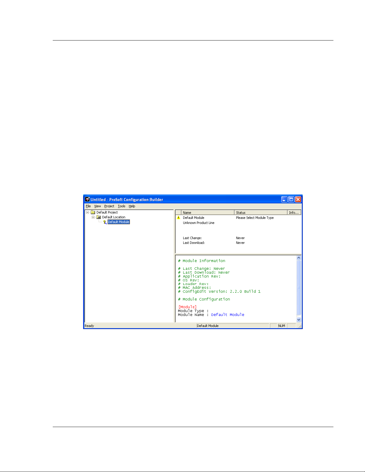
ProSoft Configuration Builder’s (PCB's) window consists of a tree view on the
left, an information pane, and a configuration pane on the right side of the
window. When you first start PCB, the tree view consists of folders for Default
Project and Default Location, with a Default Module in the Default Location
folder. The following illustration shows the PCB window with a new project.
ProSoft Technology, Inc. Page 13 of 159
August 6, 2010
Page 14
Start Here IEC-101 Slave ♦ ProLinx Communication Gateway
Protocol Manual IEC 60870-5-101 v3 Slave (Firmware version 3.xx)
To add the gateway to the project
1 Use the mouse to select DEFAULT MODULE in the tree view, and then click the
right mouse button to open a shortcut menu.
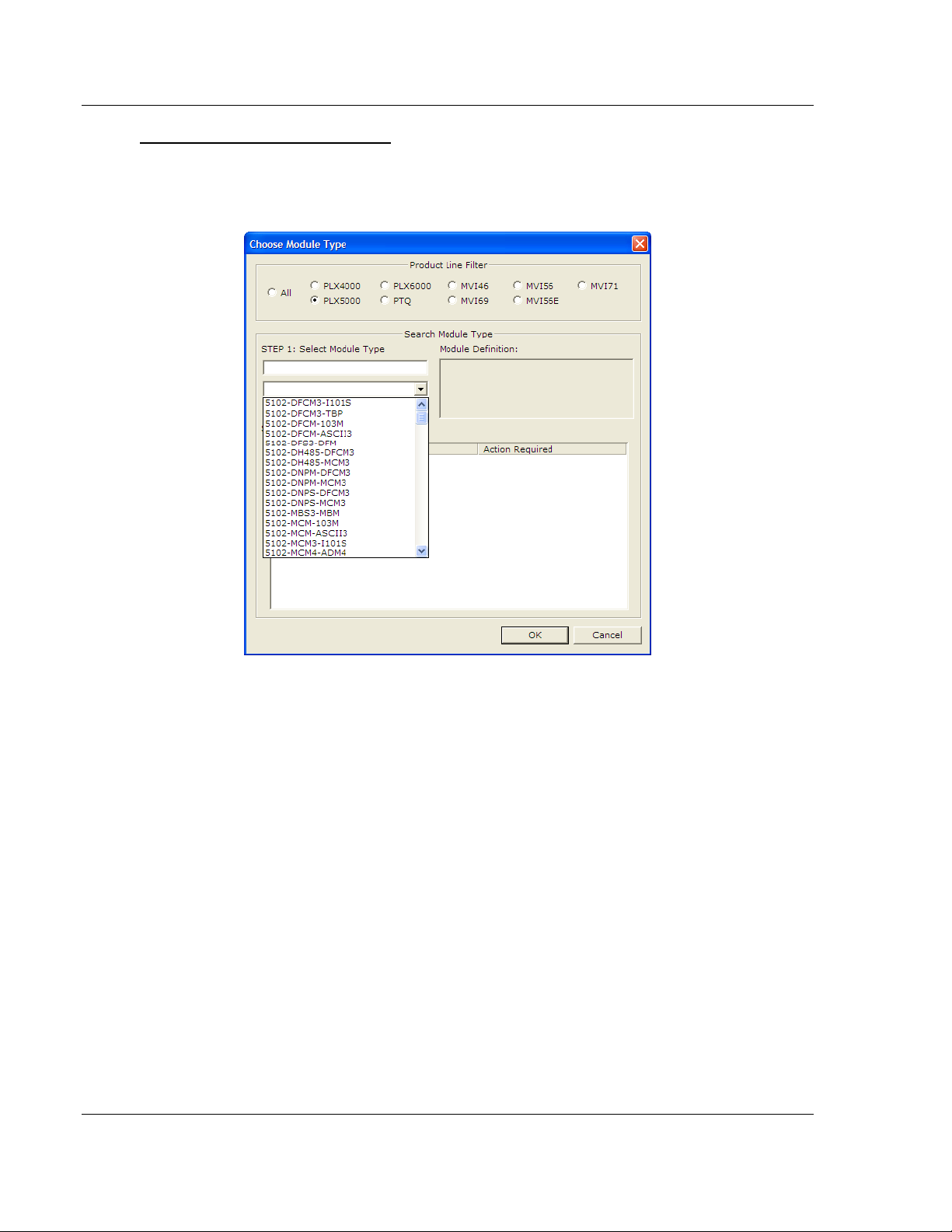
2 On the shortcut menu, choose C
Choose Module Type
dialog box.
HOOSE MODULE TYPE. This action opens the
3 In the Product Line Filter area of the dialog box, select the appropriate
product type radio button.
4
In the STEP 1: Select Module Type dropdown list, select the model number
that matches your gateway, and then click OK
return to the
PCB Main window.
to save your settings and
Page 14 of 159 ProSoft Technology, Inc.
August 6, 2010
Page 15
IEC-101 Slave ♦ ProLinx Communication Gateway Start Here
IEC 60870-5-101 v3 Slave (Firmware version 3.xx) Protocol Manual
1.4.2 Renaming PCB Objects
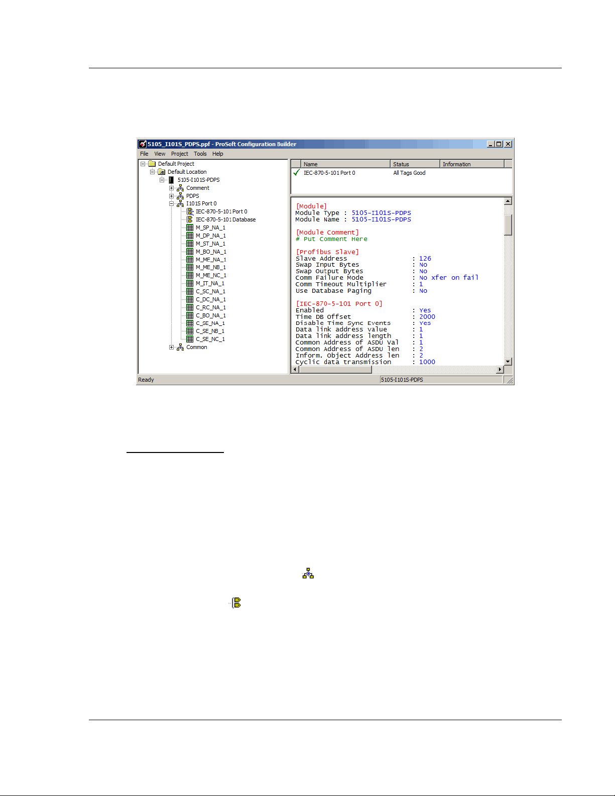
Notice that the contents of the information pane and the configuration pane
changed when you added the gateway to the project.
At this time, you may wish to rename the Default Project and Default Location
folders in the tree view.
To rename an object
1 Select the object, and then click the right mouse button to open a shortcut
menu. From the shortcut menu, choose R
ENAME.
2 Type the name to assign to the object.
3 Click away from the object to save the new name.
1.4.3 Configuring Module Parameters
1 Click on the [+] sign next to the gateway icon to expand gateway information.
2 Click on the
configuration options.
3 Double-click any
4 To edit a parameter, select the parameter in the left pane and make your
changes in the right pane.
5 Click OK
[+] sign next to any icon to view gateway information and
icon to open an Edit dialog box.
to save your changes.
ProSoft Technology, Inc. Page 15 of 159
August 6, 2010
Page 16
Start Here IEC-101 Slave ♦ ProLinx Communication Gateway
Protocol Manual IEC 60870-5-101 v3 Slave (Firmware version 3.xx)
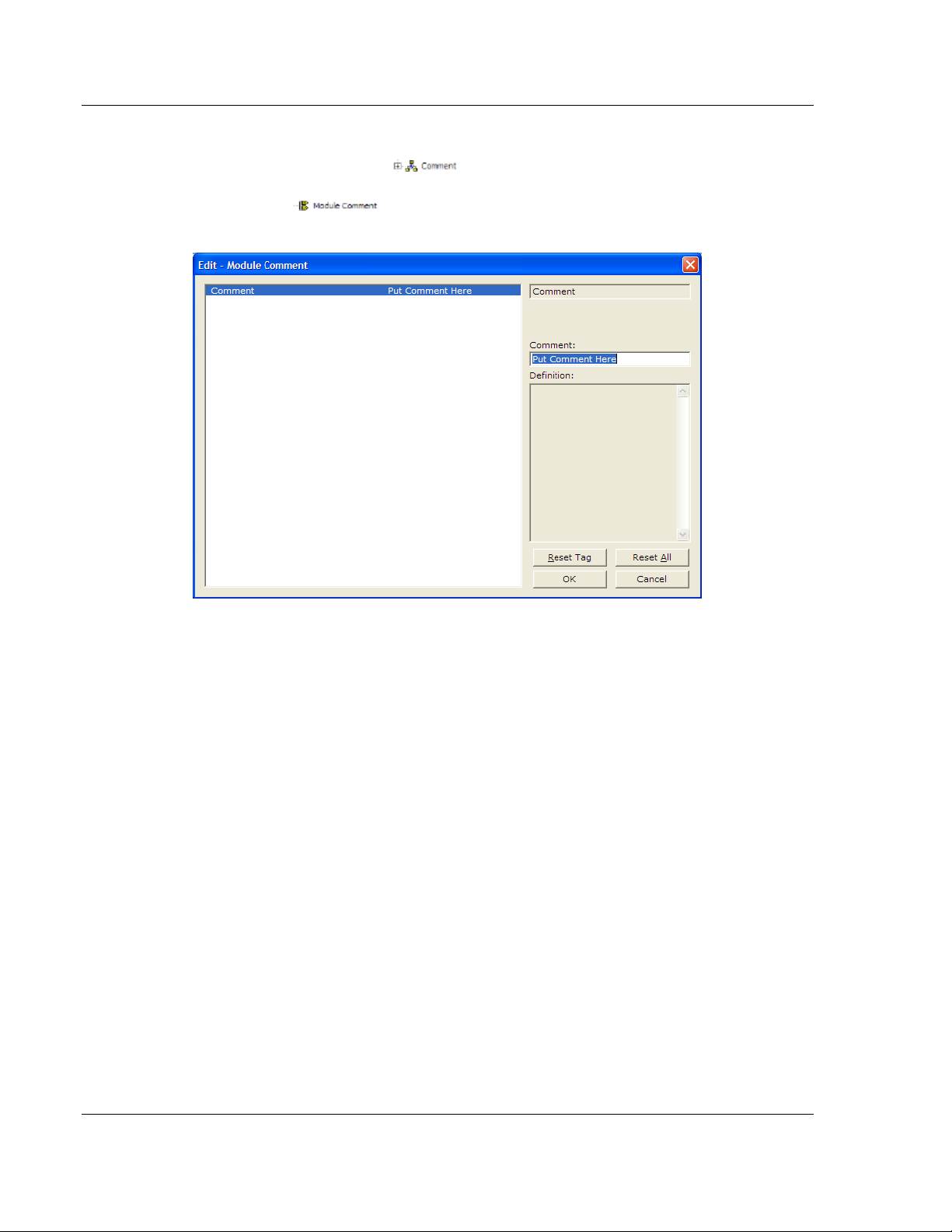
1.4.4 Creating Optional Comment Entries
1 Click the [+] to the left of the icon to expand the module
comments.
2 Double-click the
appears.
icon. The Edit - Module Comment dialog box
3 Enter your comment and click OK
to save your changes.
1.4.5 Printing a Configuration File
1 Select the gateway icon, and then click the right mouse button to open a
shortcut menu.
2 On the
View Configuration window.
3 On the View Configuration window, open the F
This action opens the Print dialog box.
4 On the Print dialog box, choose the printer to use from the drop-down list,
select printing options, and then click OK.
shortcut menu, choose VIEW CONFIGURATION. This action opens the
ILE menu, and choose PRINT.
Page 16 of 159 ProSoft Technology, Inc.
August 6, 2010
Page 17
IEC-101 Slave ♦ ProLinx Communication Gateway Start Here
IEC 60870-5-101 v3 Slave (Firmware version 3.xx) Protocol Manual
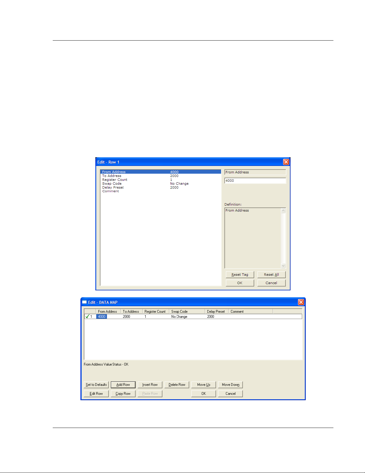
1.4.6 Using the CommonNet Data Map
The Data Map section allows you to copy data between areas in the gateway's
internal database.
You can copy a maximum of 100 registers per Data Map command, and you can
configure a maximum of 200 separate copy commands.
You can copy data from the error or status tables in upper memory to internal
database registers in the User Data memory area.
You can rearrange the byte and/or word order during the copy process. For
example, by rearranging byte or word order, you can convert floating-point values
to the correct format for a different protocol.
You can also use the Data Map to condense widely dispersed data into one
contiguous data block, making it easier to access.
ProSoft Technology, Inc. Page 17 of 159
August 6, 2010
Page 18

Start Here IEC-101 Slave ♦ ProLinx Communication Gateway
Protocol Manual IEC 60870-5-101 v3 Slave (Firmware version 3.xx)
From Address
0 to highest Status Data address
This field specifies the beginning internal database register address for the copy
operation. This address can be any valid address in the User Data Area or the
Status Data Area of the gateway.
To Address
0 to 3999
This parameter specifies the beginning destination register address for the copy
operation. This address must always be within the User Data registers area.
Take care to specify a destination address that will not overwrite data that has
been stored in memory by one of the communication protocols running on the
gateway.
Register Count
1 to 100
This parameter specifies the number of registers to copy.
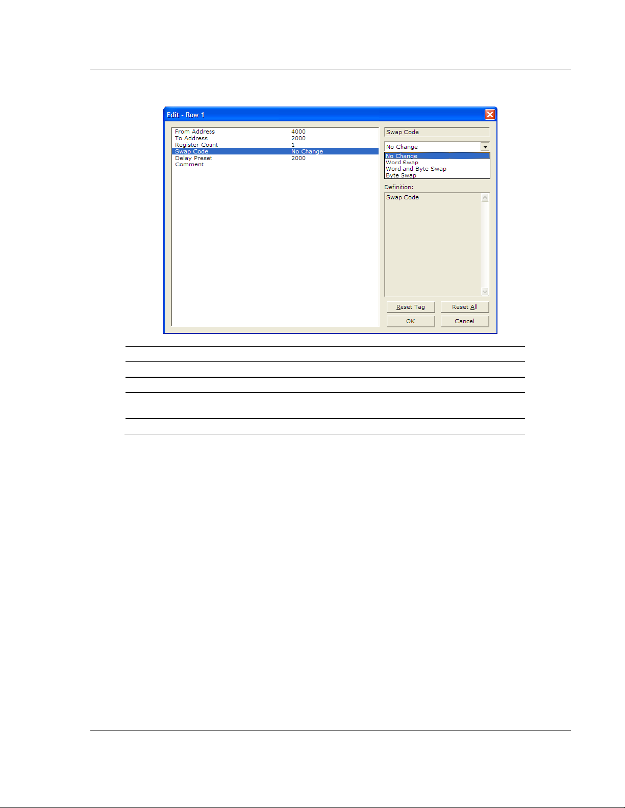
Swap Code
NO CHANGE, WORD SWAP, WORD AND BYTE SWAP, BYTE SWAP
You may need to swap the order of the bytes in the registers during the copy
process in order to change the alignment of bytes between dissimilar protocols.
This parameter is helpful when dealing with floating-point or other multi-register
values, as there is no standard method of storage of these data types in slave
devices.
Page 18 of 159 ProSoft Technology, Inc.
August 6, 2010
Page 19
IEC-101 Slave ♦ ProLinx Communication Gateway Start Here
IEC 60870-5-101 v3 Slave (Firmware version 3.xx) Protocol Manual
The following table defines the values and their associated operations:
Swap Code Description
No Swap No change is made in the byte ordering (1234 = 1234)
Word Swap The words are swapped (1234=3412)
Word and
Byte Swap
Bytes The bytes in each word are swapped (1234=2143)
The words are swapped, then the bytes in each word are swapped (1234=4321)
ProSoft Technology, Inc. Page 19 of 159
August 6, 2010
Page 20

Start Here IEC-101 Slave ♦ ProLinx Communication Gateway
Protocol Manual IEC 60870-5-101 v3 Slave (Firmware version 3.xx)
Delay Preset
This parameter sets an interval for each Data Map copy operation. The value you
put for the Delay Preset is not a fixed amount of time. It is the number of firmware
scans that must transpire between copy operations.
The firmware scan cycle can take a variable amount of time, depending on the
level of activity of the protocol drivers running on the ProLinx gateway and the
level of activity on the gateway's communication ports. Each firmware scan can
take from 1 to several milliseconds to complete. Therefore, Data Map copy
operations cannot be expected to happen at regular intervals.
If multiple copy operations (several rows in the Data map section) happen too
frequently or all happen in the same update interval, they could delay the process
scan of the gateway protocols, which could result in slow data updates or missed
data on communication ports. To avoid these potential problems, you should set
the Delay Preset to different values for each row in the Data Map section and set
them to higher, rather than lower, numbers.
For example, Delay Preset values below 1000 could begin to cause a noticeable
delay in data updates through the communication ports. And you should not set
all Delay Presets to the same value. Instead, use different values for each row in
the Data Map such as 1000, 1001, and 1002 or any other different Delay Preset
values you like. This will prevent the copies from happening concurrently and
prevent possible process scan delays.
Page 20 of 159 ProSoft Technology, Inc.
August 6, 2010
Page 21
IEC-101 Slave ♦ ProLinx Communication Gateway Start Here
IEC 60870-5-101 v3 Slave (Firmware version 3.xx) Protocol Manual
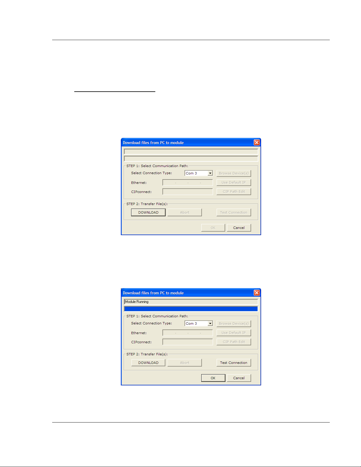
1.4.7 Downloading the Project to the Module
For the gateway to use the settings you configured, you must download (copy)
the updated Project file from your PC to the gateway.
To Download the Project File
1 In the tree view in ProSoft Configuration Builder, click once to select the
gateway.
2 Open the P
program will scan your PC for a valid com port (this may take a few seconds).
When PCB has found a valid COM port, the Download
ROJECT menu, and then choose MODULE/DOWNLOAD. The
dialog box will open.
3 Choose the COM port to use from the
D
OWNLOAD button.
dropdown list, and then click the
The gateway will perform a platform check to read and load its new settings.
When the platform check is complete, the status bar in the Download
box will display the message Module Running.
dialog
ProSoft Technology, Inc. Page 21 of 159
August 6, 2010
Page 22

Start Here IEC-101 Slave ♦ ProLinx Communication Gateway
Protocol Manual IEC 60870-5-101 v3 Slave (Firmware version 3.xx)
Page 22 of 159 ProSoft Technology, Inc.
August 6, 2010
Page 23

IEC-101 Slave ♦ ProLinx Communication Gateway 101S Protocol Configuration
IEC 60870-5-101 v3 Slave (Firmware version 3.xx) Protocol Manual
2 101S Protocol Configuration
In This Chapter
[IEC-870-5-101 Port 0] .......................................................................... 24
[IEC-870-5-101 Database]..................................................................... 38
[M_SP_NA_1] ........................................................................................ 42
[M_DP_NA_1] ....................................................................................... 42
[M_ST_NA_1] ........................................................................................ 43
[M_BO_NA_1 104] ................................................................................ 43
[M_ME_NA_1] ....................................................................................... 44
[M_ME_NB_1] ....................................................................................... 44
[M_ME_NC_1] ....................................................................................... 45
[M_IT_NA_1] ......................................................................................... 45
[C_SC_NA_1] ........................................................................................ 46
[C_DC_NA_1] ........................................................................................ 46
[C_RC_NA_1] ........................................................................................ 47
[C_BO_NA_1 104] ................................................................................. 47
[C_SE_NA_1] ........................................................................................ 48
[C_SE_NB_1] ........................................................................................ 48
[C_SE_NC_1] ........................................................................................ 49
Group Codes ......................................................................................... 50
ProSoft Technology, Inc. Page 23 of 159
August 6, 2010
Page 24
101S Protocol Configuration IEC-101 Slave ♦ ProLinx Communication Gateway
Protocol Manual IEC 60870-5-101 v3 Slave (Firmware version 3.xx)
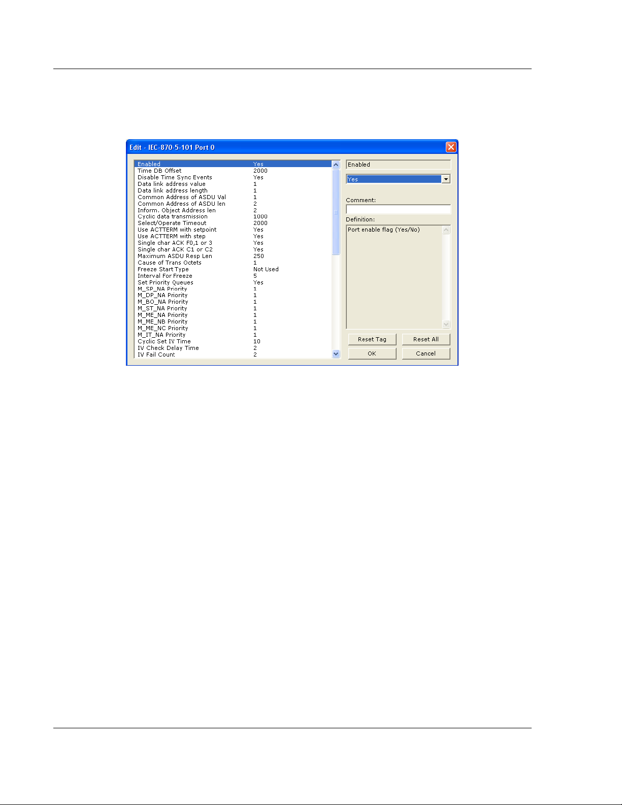
2.1 [IEC-870-5-101 Port 0]
This section provides information required to configure a slave application with
the gateway.
2.1.1 Enabled
YES or NO
Enables or disables the primary port. If the port is not enabled (No), then the
gateway will not use the port. If the port is enabled (Yes), the gateway will
emulate an IEC 60870-101 slave device on the port.
2.1.2 Time DB Offset
-1, or 0 to 3994
This parameter defines the location in the database where the time maintained
for the IEC protocol is copied. This time is updated whenever a time
synchronization command is received from the host and continually as the
program runs. If the parameter is set to -1, the time will not be placed in the
database.
Page 24 of 159 ProSoft Technology, Inc.
August 6, 2010
Page 25

IEC-101 Slave ♦ ProLinx Communication Gateway 101S Protocol Configuration
IEC 60870-5-101 v3 Slave (Firmware version 3.xx) Protocol Manual
2.1.3 Disable Time Sync Events
YES or NO
This feature can be used when the Master receives the event timestamp with
only minutes and milliseconds information for each event message (CP24 time
type). If the parameter is set to N, the spontaneous time sync events will be
generated to indicate the change of hour. If this parameter is set to Y, then the
spontaneous time sync event messages are not generated to indicate the
change of hour.
2.1.4 Data Link Address Value
0 to 65535
This parameter defines the Data Link Address for the emulated device on the
gateway. This address identifies the gateway on the network along with the
common address of ASDU.
2.1.5 Data link address length
0, 1, or 2
This parameter specifies the number of octets used for the data link address.
This parameter must be set the same for all devices on the network. A value of 0
is only valid when the balanced mode is used. If unbalanced mode is used, a
value of 1 or 2 must be used.
2.1.6 Common Address of ASDU Val
0 to 65535
This parameter specifies the common address of the ASDU (section address) for
access to data in the gateway. There is only one value entered for access to all
data in the gateway.
Refer to ASDU Configuration for more information on Application Service Data
Unit configuration.
2.1.7 Common Address of ASDU Len
1 or 2
This parameter specifies the number of octets used for the common address of
ASDU. This parameter must be set the same for all devices on the network.
ProSoft Technology, Inc. Page 25 of 159
August 6, 2010
Page 26

101S Protocol Configuration IEC-101 Slave ♦ ProLinx Communication Gateway
Protocol Manual IEC 60870-5-101 v3 Slave (Firmware version 3.xx)
2.1.8 Inform. Object Address Len
1, 2, or 3
This parameter specifies the number of octets used to define the address of an
information object (point address).
2.1.9 Cyclic Data Transmission
0 to 4,294,967,296 (2 raised to the power of 32) milliseconds
This parameter defines the number of milliseconds between cyclic updates. The
range of values allow for update times between 1 millisecond and 49.7 days. Set
this parameter to 0 to disable cyclic data reporting.
2.1.10 Select/Operate Timeout
0 to 4,294,967,296 (2 raised to the power of 32) milliseconds
This parameter sets the number of milliseconds to wait for a valid Execute
command after receiving a Select command. The range of values allows for
update times between 1 millisecond and 49.7 days. Set this parameter to 0 to
disable this feature.
2.1.11 Use ACTTERM with Set Point
Y - YES or N - NO
This parameter determines if an ACTTERM will be sent. If the parameter is set to
Y
ES, then set point commands will issue an ACTTERM when the command is
complete. If the parameter is set to N
O, ACTCON is the last response to a set
point command.
2.1.12 Use ACTTERM with Step
Y - YES or N - NO
This parameter determines if an ACTTERM will be sent. If the parameter is set to
Y
ES, then step commands will issue an ACTTERM when the command is
complete. If the parameter is set to N
O, ACTCON is the last response to a step
command.
2.1.13 Single char ACK F0, 1 or 3
Y - YES or N - NO
If set to Yes, a single character ACK (0xE5) will be sent instead of a fixed length
ACK (secondary function code 0) in response to a primary link function code 0, 1
or 3 if there is no access demand for class 1 data (ACD=1). If set to No, the fixed
length ACK will be sent.
Page 26 of 159 ProSoft Technology, Inc.
August 6, 2010
Page 27

IEC-101 Slave ♦ ProLinx Communication Gateway 101S Protocol Configuration
IEC 60870-5-101 v3 Slave (Firmware version 3.xx) Protocol Manual
2.1.14 Single char ACK C1 or C2
Y -YES or N - NO
If set to Yes, a single character ACK (0xE5) will be sent instead of a fixed length
NACK (secondary function code 9) when no response user data is available. If
set to No, the fixed length NACK will be sent.
2.1.15 Maximum ASDU Resp Len
25 to 252
Sets the maximum ASDU response message length (usually 252).
2.1.16 Cause of Trans(mission) Octets
1 or 2
Specifies the number of COT octets (1 or 2)
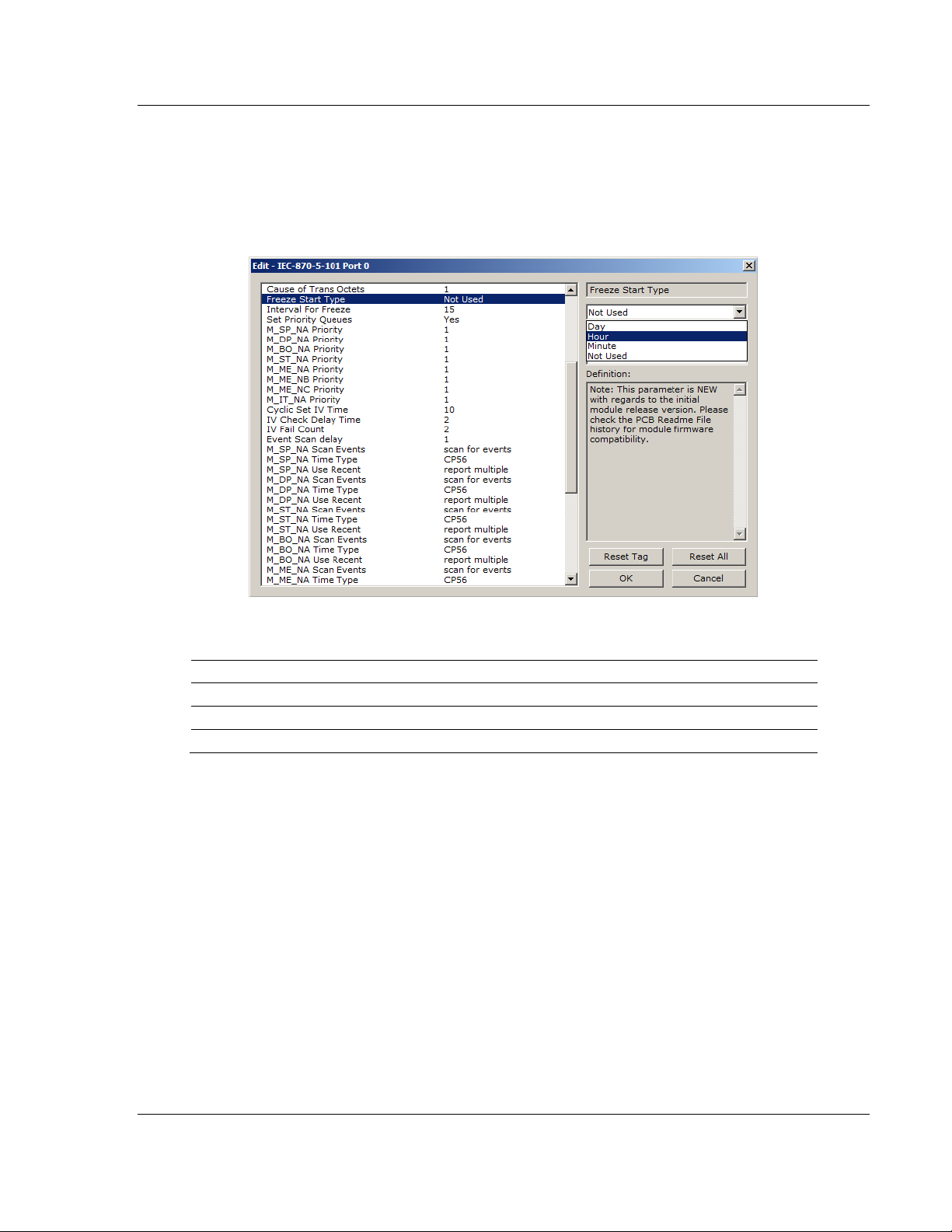
2.1.17 Freeze Start Type
D = DAY, H = HOUR, M = MINUTE, N = NOT USED The Freeze Start Type parameter defines when the gateway starts sending the
M_IT messages.
ProSoft Technology, Inc. Page 27 of 159
August 6, 2010
Page 28
101S Protocol Configuration IEC-101 Slave ♦ ProLinx Communication Gateway
Protocol Manual IEC 60870-5-101 v3 Slave (Firmware version 3.xx)
Example I - Freeze Start Type
If the gateway should send the counter points on the hourly turn around time and
also 45 minutes later, the Mode A parameters should be configured as follows:
So the gateway would send events as follows (Hours:Minutes:Seconds):
17:00:00
17:45:00
18:00:00
18:45:00
19:00:00
19:45:00
…
The following illustration shows a typical communication example when the Mode
A is selected during unbalanced mode operation:
Page 28 of 159 ProSoft Technology, Inc.
August 6, 2010
Page 29
IEC-101 Slave ♦ ProLinx Communication Gateway 101S Protocol Configuration
IEC 60870-5-101 v3 Slave (Firmware version 3.xx) Protocol Manual
Example II - Freeze Start Type
If the gateway powers up with the following date and time settings on its internal
clock:
03/25/2004 18:07:42
And if you configure the Interval For Freeze parameter to 15 seconds, as follows:
The Freeze Start Type parameter determines when the gateway will begin
sending these messages, as follows:
If the Freeze Start Type is set to: Then Messages will start being sent at:
D 03/26/2004 00:00:00 and every 15 seconds thereafter
H 03/25/2004 19:00:00 and every 15 seconds thereafter
M 03/25/2004 18:08:00 and every 15 seconds thereafter
Once message transmission begins, the gateway will freeze and transmit counter values at whatever interval has been configured using the Interval For Freeze parameter. In this example, that would be every 15-seconds.
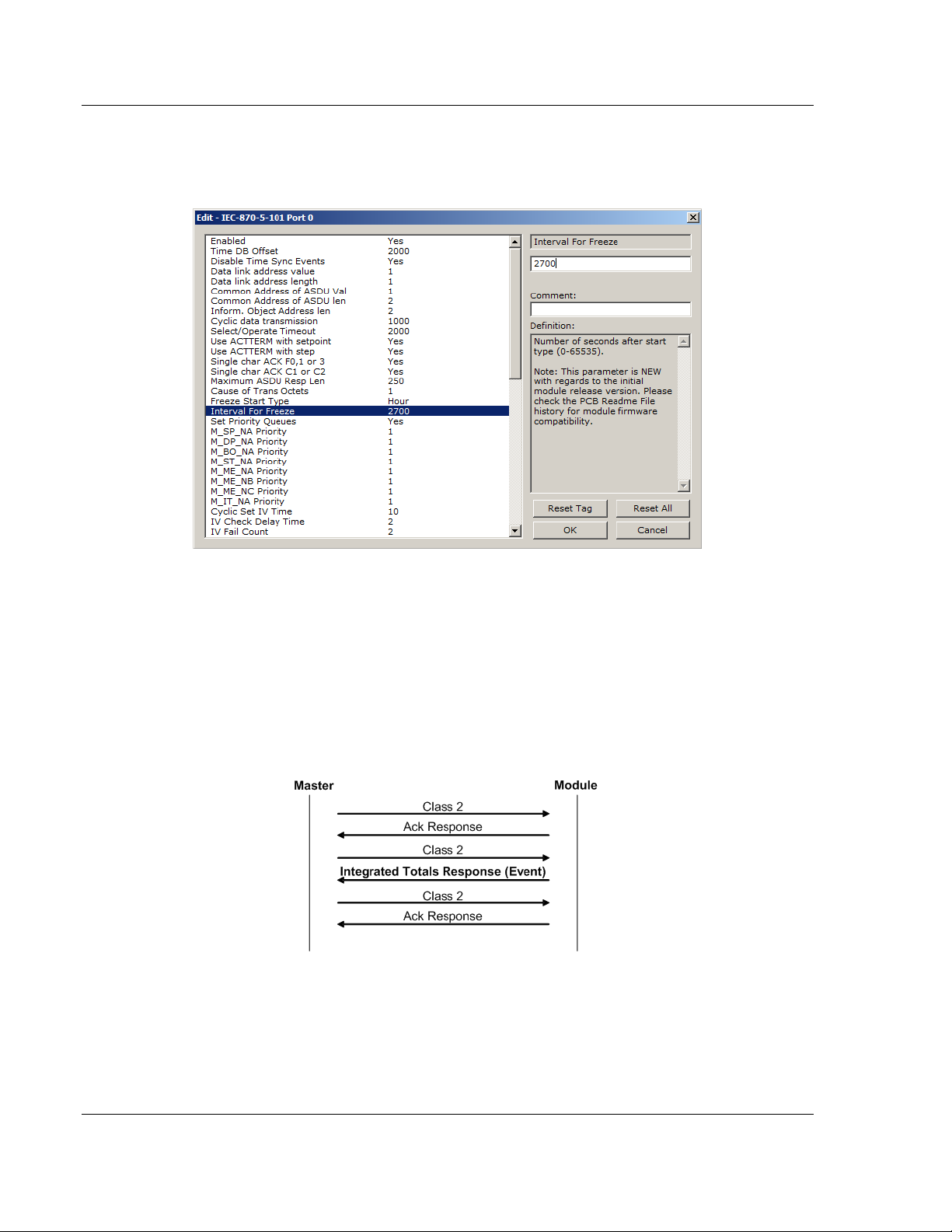
2.1.18 Interval for Freeze
0 to 65535 seconds
Freeze Start Type and Interval for Freeze are used if Mode A operation is to be
used for the counter freeze operation. If they are not used, the gateway will
operate in Mode D.
ProSoft Technology, Inc. Page 29 of 159
August 6, 2010
Page 30
101S Protocol Configuration IEC-101 Slave ♦ ProLinx Communication Gateway
Protocol Manual IEC 60870-5-101 v3 Slave (Firmware version 3.xx)
2.1.19 Set Priority Queues
YES or NO
This section defines priority queues for the gateway. You can assign priorities to
data types that return events so that events of some data types will be returned
before events of other data types. If this feature is utilized, each data type must
be assigned a unique index from 0 to 7. The lower the index, the higher the
priority (0=highest priority, 7=lowest priority).
Events of ASDUs with lower numbers will be reported before events from other
ASDUs with higher numbers.
Note: In some configurations, depending on the total number of events generated for all data
types, setting priorities may cause some events to be lost, as the event buffers for low priority
queues may overflow before their events can be reported.
For more information, refer to Event Priority (page 31).
Page 30 of 159 ProSoft Technology, Inc.
August 6, 2010
Page 31

IEC-101 Slave ♦ ProLinx Communication Gateway 101S Protocol Configuration
IEC 60870-5-101 v3 Slave (Firmware version 3.xx) Protocol Manual
2.1.20 Event Priority
Event Priority permits the user to set reporting priorities for data change events
generated for each data type. The configuration file contains the following
parameters to support this feature:
The Set Priority Queues parameter must be enabled for this feature to be used.
Each of the Monitored Point ASDUs must be assigned a unique priority index
from 0 to 7. When events of the ASDU with a lower priority number are present,
they will always be reported before events from any other ASDUs with higher
priority numbers.
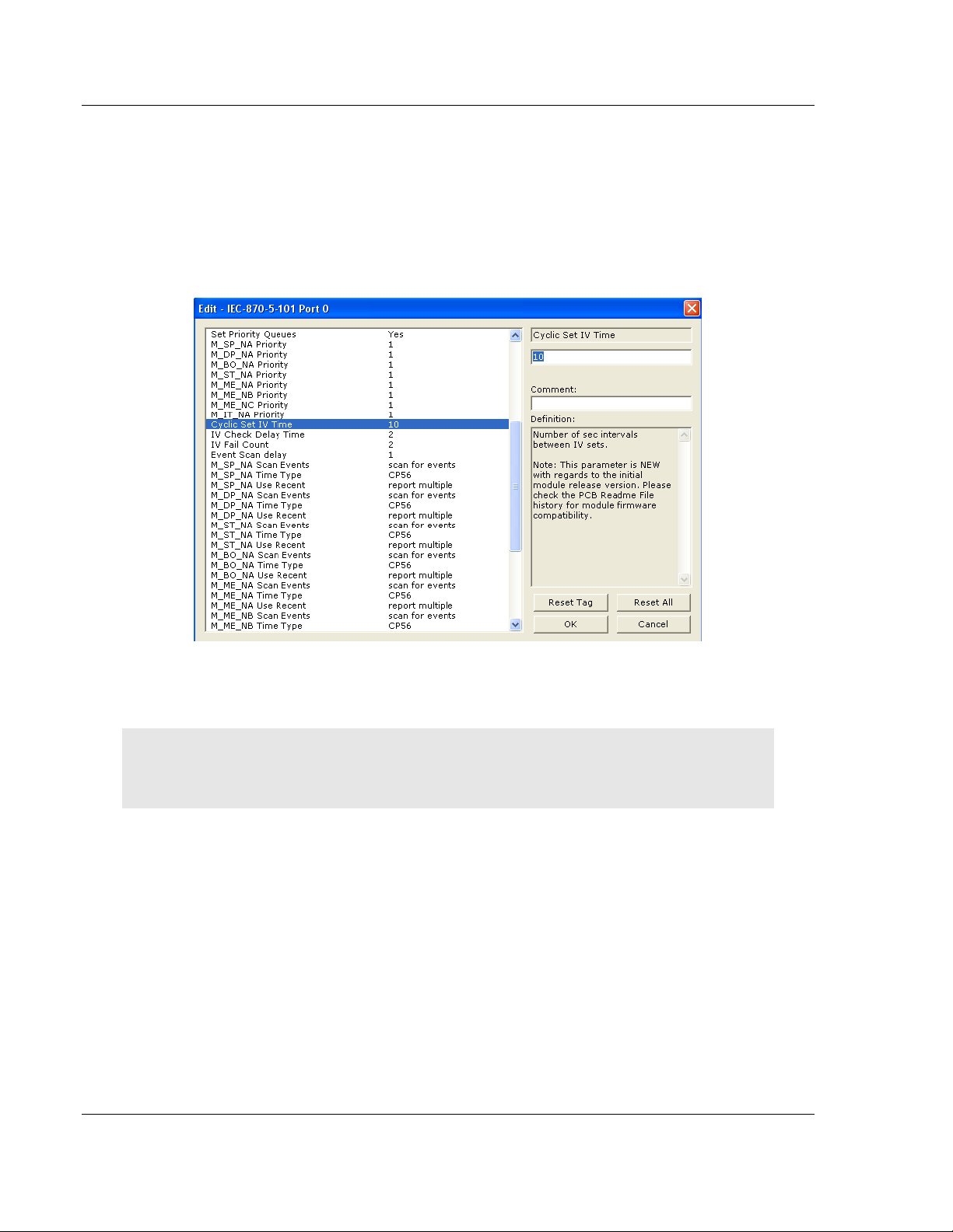
2.1.21 Cyclic Set IV Time - PLX 101S
1 to 65535 seconds, or 0 to disable Invalid Bit Monitoring
The parameter should be set to a value significantly greater than the value of the
IV Check Delay Time parameter, multiplied by the value of the IV Fail Count
parameter. Example:
If, IV Check Delay = 3;
And, IV Fail Count = 5;
Then set Cyclic Set IV Time significantly greater than 15; preferably some
multiple of this value, like 30, 45, 60,
The Cyclic Set IV Time parameter is one of three parameters needed to establish
a fail-safe data validation system for this protocol implementation. This
parameter is used with the IV Check Delay Time and the IV Fail Count
parameters to create a way to alert the remote IEC-101 Master to situations
where data being sent by the gateway might be invalid.
or more.
ProSoft Technology, Inc. Page 31 of 159
August 6, 2010
Page 32

101S Protocol Configuration IEC-101 Slave ♦ ProLinx Communication Gateway
Protocol Manual IEC 60870-5-101 v3 Slave (Firmware version 3.xx)
The gateway will automatically set ON (set to one) the IV Bits of all IEC database
Monitor Points (M_xx_xx point) that have been configured to use invalid bit
monitoring. This means that all IEC database Monitor Points configured with IV
Bit addresses greater than zero (0) will have their IV Bit addresses in the
gateway database set to a value of one (1) by the gateway firmware in a timed,
periodic cycle, based on the number of seconds entered in Cyclic Set IV Time.
The IV Bits are checked at the interval specified by the IV Check Delay Time
parameter. At the end of each check delay interval, if an IV Bit for any IEC
database point is ON, an IV Bit Check Fail accumulator for that point will be
incremented. If the value in any IV Bit Check Fail accumulator becomes equal to
the value of the IV Fail Count parameter, the gateway will consider the data value
of that point invalid and will report the invalid status of that point to the Master
along with the data value.
If the IV Bit is cleared (reset, set OFF, set to zero) before the IV Bit Check Fail
accumulator value becomes equal to the value of the IV Fail Count parameter,
the IV Bit Check Fail accumulator will be reset to 0. The gateway will consider the
data value of that point valid and will report the valid status of that point to the
Master along with data value.
To properly use data validity checking with a ProLinx Gateway, the application
that communicates to the gateway through the other gateway protocol (Modbus,
EtherNet/IP, etc.) must be programmed to provide data validity information, as
well as the actual data to be transferred. This other application must write bit
values of zero (0) or one (1) to the proper gateway database addresses along
with the data for each IEC database point.
This means the other protocol application will be responsible for clearing the IV
Bits for data points which contain valid data at a time interval less than the
amount of time required to accumulate the required number of IV Bit Check
failures. If the other protocol application does not clear the IV Bits, then those
IEC database monitor point values will be reported to the Master as invalid.
NOTE: If one or more of the Cyclic Set IV Time, the IV Check Delay Time, or the IV Fail Count
parameters are set to zero, the data validity checking feature will be disabled for all points in the
IEC database and the data reported to the remote Master will always be reported as valid data. If
you wish to have actual data validity information relayed to the Master, be sure the Cyclic Set IV
Time, the IV Check Delay Time, and the IV Fail Count parameters are set to non-zero values and
be sure the application has been programmed to properly manipulate the IV Bit addresses in the
gateway database. Once data validity checking has been enabled, you can still turn off validity
checking on a point-by-point basis by setting the IV Bit Address to zero (0) for any point you wish to
exclude from data validity checking and reporting.
For more information on the data validity features of this protocol implementation,
refer to Invalid Bit Monitoring.
Page 32 of 159 ProSoft Technology, Inc.
August 6, 2010
Page 33

IEC-101 Slave ♦ ProLinx Communication Gateway 101S Protocol Configuration
IEC 60870-5-101 v3 Slave (Firmware version 3.xx) Protocol Manual
2.1.22 IV Check Delay Time
1 to 65535 seconds, or 0 to disable Invalid Bit Monitoring
This parameter sets the number of seconds between IV Bit value checks. Every
IEC database Monitor information object which has an IV Bit address set greater
than 0 will have that bit address checked at the interval specified by this
parameter.
Setting this parameter to zero (0) will disable data validity checking.
2.1.23 IV Fail Count
1 to 65535 seconds, or 0 to disable Invalid Bit Monitoring
This parameter sets the number of successive IV Bit check failures which must
occur before the data from an IEC database Monitor information object will be
reported to the remote Client as invalid data.
An IV Bit Check Failure occurs when the IV Bit value in the gateway database is set ON {when it contains a value of one (1)} at the time an IV Bit Check is performed. IV Bit Check failures are counted and held in separate IV Bit Check Failure accumulators for each IEC Monitor information object configured for validity checking. If the value in any point's failure accumulator becomes equal to the value set in this IV Fail Count parameter, the gateway will consider data from this point as invalid and report to the Client this invalid status, along with the point's data value.
Setting this parameter to zero (0) will disable data validity checking.
2.1.24 Event Scan Delay
1 to 65535 milliseconds, or 0 to disable
If set to 0, the feature will be disabled and the gateway will not generate any
events. If set from 1 to 65535, the parameter represents the number of
milliseconds between event scanning. This parameter defines how often the
program will scan for new events in the databases.
NOTE: The lower you set this value, the more negative effect it will have on overall gateway data
update and transfer performance. Scanning for new events causes an interrupt of other data
manipulation functions. The more often these scan interrupts occur, the less processor time the
gateway will have available for other data operations. When choosing a value for this parameter,
you should consider such factors as how often events might be generated by your application and
how often you need to recognize and respond to such events. This will allow you to set this value
as high as it can be set and still maintain your overall event capturing and reporting strategy.
Doing so can reduce the amount of interrupts, prevent excessive event scanning, and maximize
data update and transmission rates.
ProSoft Technology, Inc. Page 33 of 159
August 6, 2010
Page 34

101S Protocol Configuration IEC-101 Slave ♦ ProLinx Communication Gateway
Protocol Manual IEC 60870-5-101 v3 Slave (Firmware version 3.xx)
2.1.25 Scan Events
[0] = NO SCANNING or [1] = SCAN FOR EVENTS
Separate parameters exist for each monitored point type and define whether or
not events of that particular point type will be generated by the gateway. If the Scan Events parameter is set to zero generated. If this parameter is set to [1] or S scanned and generated on data change.
[0] or NO SCANNING, then events will not be
CAN FOR EVENTS, events will be
Page 34 of 159 ProSoft Technology, Inc.
August 6, 2010
Page 35

IEC-101 Slave ♦ ProLinx Communication Gateway 101S Protocol Configuration
IEC 60870-5-101 v3 Slave (Firmware version 3.xx) Protocol Manual
2.1.26 Time Type
[0] = None, [1] = CP24, or [2] = CP56
Separate parameters exist for multiple point types. This parameter defines the
time format used with data events.
2.1.27 Use Balanced Mode
Y - YES or N - NO
This parameter specifies if the port will use balanced mode. If balanced mode is
used, only one controlled station will be permitted on the port. If unbalanced
mode is used, multiple controlled stations can be used on a port.
Refer to gateway Initialization for more information on these modes.
2.1.28 Retry Count
0 to 255
In balanced mode, this parameter specifies the number of retries (0 to 255) if a
response is not received. In unbalanced mode, this parameter is ignored.
ProSoft Technology, Inc. Page 35 of 159
August 6, 2010
Page 36

101S Protocol Configuration IEC-101 Slave ♦ ProLinx Communication Gateway
Protocol Manual IEC 60870-5-101 v3 Slave (Firmware version 3.xx)
2.1.29 Response Timeout
0 to 65535 milliseconds
This parameter specifies the minimum number of milliseconds to wait for a
response to a primary message. Do not set this parameter too small or timeout
conditions may prevent successful data transmission. If the timeout is
recognized, the message will be retransmitted up to the number of times
specified in the Retry Count parameter. This parameter is only used in balance
mode.
2.1.30 Baud Rate
300, 600, 1200, 2400, 4800, 9600, 19200, or 38400
This parameter specifies the baud rate for the primary port on the gateway. Baud
rates from 300 to 38400 are supported on the gateway.
2.1.31 Parity
None, Odd, Even
Parity is a simple error checking algorithm used in serial communication. This
parameter specifies the type of parity checking to use.
All devices communicating through this port must use the same parity setting.
2.1.32 RTS On
0 to 65535 milliseconds
This parameter sets the number of milliseconds to delay after Ready To Send
(RTS) is asserted before data will be transmitted.
2.1.33 RTS Off
0 to 65535 milliseconds
This parameter sets the number of milliseconds to delay after the last byte of
data is sent before the RTS modem signal will be set low.
2.1.34 Minimum Delay
0 to 65535 milliseconds
This parameter defines the minimum number of milliseconds to wait before a
response is sent from the unit.
Page 36 of 159 ProSoft Technology, Inc.
August 6, 2010
Page 37

IEC-101 Slave ♦ ProLinx Communication Gateway 101S Protocol Configuration
IEC 60870-5-101 v3 Slave (Firmware version 3.xx) Protocol Manual
2.1.35 Receive Timeout
0 to 65535 milliseconds
This parameter specifies the minimum number of milliseconds to wait after the
first byte of a frame is received before a timeout condition is set. Be careful not to
set this parameter too small. If the timeout condition is set, all bytes in the frame
received will be discarded.
2.1.36 Hardware Handshaking
NONE, RTS/CTS, DTR/DSR, MODEM
Selects the hardware handshaking type. RTS/CTS, DTR/DSR and M
options are most commonly used for older telephone line modems. RTS/CTS
and DTR/DSR are also commonly used with leased-line data modems. The
M
ODEM option is also commonly used with dial-up modems. When the messages
must go out if the modem is not connected, the gateway will assert the DTR line
which will cause the modem to dial the number in the modem’s configuration.
The gateway does not have the functionality to dial the number to be called for
the modem. The gateway reconnects after 30 seconds of inactivity.
ODEM
ProSoft Technology, Inc. Page 37 of 159
August 6, 2010
Page 38

101S Protocol Configuration IEC-101 Slave ♦ ProLinx Communication Gateway
Protocol Manual IEC 60870-5-101 v3 Slave (Firmware version 3.xx)
2.2 [IEC-870-5-101 Database]
This section configures the IEC-870-5-101 Database.
2.2.1 Short Pulse Time
0 to 2,147,483,647 (2 raised to the power of 31, minus 1) milliseconds
This parameter defines the number of milliseconds to be associated with a short
pulse command.
2.2.2 Long Pulse Time
0 to 2,147,483,647 (2 raised to the power of 31, minus 1) milliseconds
This parameter defines the number of milliseconds to be associated with a long
pulse command.
Page 38 of 159 ProSoft Technology, Inc.
August 6, 2010
Page 39

IEC-101 Slave ♦ ProLinx Communication Gateway 101S Protocol Configuration
IEC 60870-5-101 v3 Slave (Firmware version 3.xx) Protocol Manual
2.2.3 Point Count
Point Count configuration ranges in the following configuration items are based
on the assumption that you will be using only one of the available data types for
your application. The number of point counts you configure will have an effect on
gateway performance, in particular, the accuracy of the gateway’s internal clock.
Parameter Description Range
M_SP_NA point count The number of point values assigned in monitored
single-point database.
M_DP_NA point count The number of point values assigned in monitored
double-point database.
M_ST_NA point count The number of point values assigned in monitored
step-point database.
M_BO_NA point count The number of 32-bit values assigned in monitored
bitstring database
M_ME_NA point count The number of point values assigned in monitored
normalized-point database.
M_ME_NB point count The number of point values assigned in monitored
scaled-point database.
M_ME_NC point count The number of point values assigned in monitored
scaled short-float point database.
M_IT_NA point count The number of point values assigned in monitored
counter-point database.
C_SC_NA point count The number of point values assigned in command
single-point database.
C_DC_NA point count The number of point values assigned in command
dual-point database.
0 to 1000
0 to 1000
0 to 1000
0 to 1000
0 to 1000
0 to 1000
0 to 50
0 to 99
0 to 1000
0 to 1000
ProSoft Technology, Inc. Page 39 of 159
August 6, 2010
Page 40

101S Protocol Configuration IEC-101 Slave ♦ ProLinx Communication Gateway
Protocol Manual IEC 60870-5-101 v3 Slave (Firmware version 3.xx)
Parameter Description Range
C_RC_NA point count The number of point values assigned in command
step-point database.
C_BO_NA point count The number of 32-bit values assigned in command
bitstring database
C_SE_NA point count The number of point values assigned in command
normalized-point database.
C_SE_NB point count The number of point values assigned in command
scaled-point database.
C_SE_NC point count The number of point values assigned in command
short-float point database.
0 to 1000
0 to 1000
0 to 1000
0 to 1000
0 to 50
2.2.4 Sequence Flag
In order to save bandwidth, you can configure the gateway to use the Sequence
Flag feature. If this feature is not selected, the gateway will send the Information
Object Address (IOA) and the data value for every Monitor information object in
a poll response to the Master. If this parameter is enabled, the gateway will turn
on the Sequence Flag bit in a Monitor response; send the Informaiton Object
Address of only the first object in the response, along with its data value; and
send only the data values for all the other information objects in the response.
The Master assumes that all other points use IOAs in a contiguous order (using
the first point as the starting reference address). Since the IOAs are omitted for
all but the first point, this feature allows each message packet to contain more
process data, which improves network throughput and optimizes bandwidth
utilization.
Page 40 of 159 ProSoft Technology, Inc.
August 6, 2010
Page 41

IEC-101 Slave ♦ ProLinx Communication Gateway 101S Protocol Configuration
IEC 60870-5-101 v3 Slave (Firmware version 3.xx) Protocol Manual
2.2.5 Parameter Offset
This parameter specifies the IOA (Information Object Address) offset to the
parameter data for the normalized parameter data. The value entered is added to
the Information Object address for the associated point to compute the
parameter IOA address.
The Master may send a "Parameter of Measured Normalized" or "Parameter of
Measured Scaled" command using the parameter IOA in order to change the
deadband values for specific points.
Note: The Low Limit and High Limit values are always calculated based on the deadband value as
described in the following table.
Point Value
Threshold Determined by the deadband set in the configuration file or altered by the write
command.
Low Last reported event value - threshold.
High Last reported event value + threshold.
For example, if the configuration sets two M_ME_NA points with IOA (Point #) of
600 and 601 and an M_ME_NA Parameter Offset value of 3000, it would result in
the parameter points shown in the table.
ProSoft Technology, Inc. Page 41 of 159
August 6, 2010
Page 42

101S Protocol Configuration IEC-101 Slave ♦ ProLinx Communication Gateway
Protocol Manual IEC 60870-5-101 v3 Slave (Firmware version 3.xx)
2.3 [M_SP_NA_1]
This section defines the monitored single-point database. This information is
sourced from the database and is transferred to the remote Master unit.
This section takes the following parameters:
P
OINT #
DB
G
IV
ADDRESS
ROUPS (page 50)
DB BIT
Each point consumes one bit (1 = On, 0 = Off state). The DB
corresponds to the bit offset address in the database.
The DB
ADDRESS should be located in a database area that is being constantly
moved from the gateway to the Master.
For additional information on how to set these parameters, see the Reference
chapter of this manual.
2.4 [M_DP_NA_1]
This section defines the monitored dual-point database. This information is
sourced from the database and is transferred to the remote Master unit.
This section takes the following parameters:
P
OINT #
DB
G
IV
Each point consumes two bits (00 = intermediate, 01 = off, 10 = on and 11 =
intermediate). The DB
the database.
The DB
moved from the gateway to the Master.
For additional information on how to set these parameters, see the Reference
chapter of this manual.
ADDRESS
ROUPS (page 50)
DB BIT
ADDRESS should be located in a database area that is being constantly
ADDRESS VALUE
ADDRESS value corresponds to the bit offset address in
Page 42 of 159 ProSoft Technology, Inc.
August 6, 2010
Page 43

IEC-101 Slave ♦ ProLinx Communication Gateway 101S Protocol Configuration
IEC 60870-5-101 v3 Slave (Firmware version 3.xx) Protocol Manual
2.5 [M_ST_NA_1]
This section defines the monitored step database. This information is sourced
from the database and is transferred to the remote Master unit.
This section takes the following parameters:
P
OINT #
DB
G
IV
ADDRESS
ROUPS (page 50)
DB BIT
Each point consumes one, 8-bit byte. The
byte offset address in the database.
The DB
ADDRESS should be located in a database area that is being constantly
moved from the gateway to the Master.
For additional information on how to set these parameters, see the Reference
chapter of this manual.
2.6 [M_BO_NA_1 104]
This section defines the Monitored 32-bit Bitstring Data Point database. This
information is sourced from the database and is transferred to the remote Master
unit.
This section takes the following parameters:
Point #
DB Address
Groups (page 50)
IV DB Bit
Each point is four 8-bit bytes (two 16-bit words) and the DB Address value
corresponds to the double word offset in the gateway memory database.
The DB address should be located in a database area that is being constantly
moved from the gateway to the Master.
For additional information on how to set these parameters, see the Reference
chapter of this manual.
DB ADDRESS value corresponds to the
ProSoft Technology, Inc. Page 43 of 159
August 6, 2010
Page 44

101S Protocol Configuration IEC-101 Slave ♦ ProLinx Communication Gateway
Protocol Manual IEC 60870-5-101 v3 Slave (Firmware version 3.xx)
2.7 [M_ME_NA_1]
This section defines the monitored measured value, normalized database. This
information is sourced from the database and is transferred to the remote Master
unit.
To determine the IOA (Information Object Address) for each object, add the
P
OINT # in the following section to the value of the M_ME_NA parameter offset
parameter set in the previous section.
This section takes the following parameters:
P
OINT #
DB
G
D
IV
Each point consumes one, 16-bit word. The DB
the word offset address in the database.
The DB
moved from the gateway to the Master.
For additional information on how to set these parameters, see the Reference
chapter of this manual.
ADDRESS
ROUPS (page 50)
EFAULT DEADBAND
DB BIT
ADDRESS should be located in a database area that is being constantly
ADDRESS value corresponds to
2.8 [M_ME_NB_1]
This section defines the monitored measured value, scaled database. This
information is sourced from the database and is transferred to the remote Master
unit.
To determine the IOA (Information Object Address) for each object, add the
P
OINT # in the following section to the value of the M_ME_NB parameter offset
parameter set in the previous section.
This section takes the following parameters:
P
OINT #
DB
G
D
IV
Each point consumes one, 16-bit word. The DB
the word offset address in the database.
The DB
moved from the gateway to the Master.
For additional information on how to set these parameters, see the Reference
chapter of this manual.
ADDRESS
ROUPS (page 50)
EFAULT DEADBAND
DB BIT
ADDRESS should be located in a database area that is being constantly
ADDRESS value corresponds to
Page 44 of 159 ProSoft Technology, Inc.
August 6, 2010
Page 45

IEC-101 Slave ♦ ProLinx Communication Gateway 101S Protocol Configuration
IEC 60870-5-101 v3 Slave (Firmware version 3.xx) Protocol Manual
2.9 [M_ME_NC_1]
This section defines the monitored short-float point database. This information is
sourced from the database and is transferred to the remote Master unit.
To determine the IOA (Information Object Address) for each object, add the
P
OINT # in the following section to the value of the M_ME_NC Parameter Offset
parameter set in the previous section.
This section takes the following parameters:
P
OINT #
DB
G
D
IV
Each point consumes four 8-bit bytes (two 16-bit words). The DB
corresponds to the double-word offset address in the database.
The DB
moved from the gateway to the Master.
For additional information on how to set these parameters, see the Reference
chapter of this manual.
ADDRESS
ROUPS (page 50)
EFAULT DEADBAND
DB BIT
ADDRESS value
ADDRESS should be located in a database area that is being constantly
2.10 [M_IT_NA_1]
This section defines the monitored integrated totals (counter) database. This
information is sourced from the database and is transferred to the remote Master
unit. This section takes the following parameters:
P
OINT #
DB
G
IV
Each point consumes four 8-bit bytes (two 16-bit words). The DB
corresponds to the double-word offset address in the database.
The DB
moved from the gateway to the Master.
For additional information on how to set these parameters, see the Reference
chapter of this manual.
ADDRESS
ROUPS (page 50)
DB BIT
ADDRESS should be located in a database area that is being constantly
ADDRESS value
ProSoft Technology, Inc. Page 45 of 159
August 6, 2010
Page 46

101S Protocol Configuration IEC-101 Slave ♦ ProLinx Communication Gateway
Protocol Manual IEC 60870-5-101 v3 Slave (Firmware version 3.xx)
2.11 [C_SC_NA_1]
This section defines the single point command database. This information is
sourced from the remote Master and is transferred to the database.
You can associate a command with a monitored single-point database value to
coordinate the command/monitor operation. You must enter the correct M
POINT # and MONITOR DB ADDRESS values in the table. If the REQUIRE SELECT
parameter is not set to zero, a select command must be received before an
execute command will be processed.
This section takes the following parameters:
P
OINT #
DB
M
M
R
Each point consumes one bit. The DB
offset in the database.
The DB
moved from the Master to the gateway.
For additional information on how to set these parameters, see the Reference
chapter of this manual.
ADDRESS
ONITOR POINT #
ONITOR DB ADDRESS
EQUIRE SELECT
ADDRESS should be located in a database area that is being constantly
ONITOR
ADDRESS value corresponds to the bit
2.12 [C_DC_NA_1]
This section defines the double point command database. This information is
sourced from the remote Master and is transferred to the database.
You can associate a command with a monitored double point database value to
coordinate the command/monitor operation. You must enter the correct M
POINT # and MONITOR DB ADDRESS values in the table. If the REQUIRE SELECT
parameter is not set to zero, a select command must be received before an
execute command will be processed.
This section takes the following parameters:
P
OINT #
DB
M
M
R
Each point consumes two bits. The DB
offset in the database.
The DB
moved from the Master to the gateway.
For additional information on how to set these parameters, see the Reference
chapter of this manual.
ADDRESS
ONITOR POINT #
ONITOR DB ADDRESS
EQUIRE SELECT
ADDRESS should be located in a database area that is being constantly
ONITOR
ADDRESS value corresponds to the bit
Page 46 of 159 ProSoft Technology, Inc.
August 6, 2010
Page 47

IEC-101 Slave ♦ ProLinx Communication Gateway 101S Protocol Configuration
IEC 60870-5-101 v3 Slave (Firmware version 3.xx) Protocol Manual
2.13 [C_RC_NA_1]
This section defines the step command database. This information is sourced
from the remote Master and is transferred to the database.
You can associate a command with a monitored single-point database value to
coordinate the command/monitor operation. You must enter the correct M
POINT # and MONITOR DB ADDRESS values in the table. If the REQUIRE SELECT
parameter is not set to zero, a select command must be received before an
execute command will be processed.
This section takes the following parameters:
P
OINT #
DB
M
M
Each point consumes one byte. T
ADDRESS
ONITOR POINT #
ONITOR DB ADDRESS
HE DB ADDRESS value corresponds to the byte
offset in the database.
The DB
ADDRESS should be located in a database area that is being constantly
moved from the Master to the gateway.
For additional information on how to set these parameters, see the Reference
chapter of this manual.
ONITOR
2.14 [C_BO_NA_1 104]
This section defines the Command 32-bit Bitstring Point database. This
information is sourced from the remote Master and is transferred to the database.
You can associate a command with a Monitored Double-Point database value to
coordinate the command/monitor operation. You must enter the correct Monitor
Point # and Monitor DB Address values in the table. If the Require Select
parameter is not set to zero, a select command must be received before an
execute command will be processed.
This section takes the following parameters:
Point #
DB Address
Monitor Point #
Monitor DB Address
Each point is four 8-bit bytes and the DB Address value corresponds to the
double word offset in the gateway memory database.
The DB address should be located in a database area that is being constantly
moved from the Master to the gateway.
For additional information on how to set these parameters, see the Reference
chapter of this manual.
ProSoft Technology, Inc. Page 47 of 159
August 6, 2010
Page 48

101S Protocol Configuration IEC-101 Slave ♦ ProLinx Communication Gateway
Protocol Manual IEC 60870-5-101 v3 Slave (Firmware version 3.xx)
2.15 [C_SE_NA_1]
This section defines the normalized setpoint database. This information is
sourced from the remote Master and is transferred to the database.
You can associate a command with a monitored single-point database value to
coordinate the command/monitor operation. You must enter the correct M
ONITOR
POINT # and MONITOR DB ADDRESS values in the table. If the REQUIRE SELECT
parameter is not set to zero, a select command must be received before an
execute command will be processed.
This section takes the following parameters:
P
OINT #
DB
M
M
R
Each point consumes one word. The DB
ADDRESS
ONITOR POINT #
ONITOR DB ADDRESS
EQUIRE SELECT
ADDRESS value corresponds to the word
offset in the database.
The
DB ADDRESS should be located in a database area that is being constantly
moved from the Master to the gateway.
For additional information on how to set these parameters, see the Reference
chapter of this manual.
2.16 [C_SE_NB_1]
This section defines the scaled setpoint database. This information is sourced
from the remote Master and is transferred to the database.
You can associate a command with a monitored single-point database value to
coordinate the command/monitor operation. You must enter the correct M
ONITOR
POINT # and MONITOR DB ADDRESS values in the table. If the REQUIRE SELECT
parameter is not set to zero, a select command must be received before an
execute command will be processed.
This section takes the following parameters:
P
OINT #
DB
M
M
R
Each point consumes one word. The DB
ADDRESS
ONITOR POINT #
ONITOR DB ADDRESS
EQUIRE SELECT
ADDRESS value corresponds to the word
offset in the database.
The
DB ADDRESS should be located in a database area that is being constantly
moved from the Master to the gateway.
For additional information on how to set these parameters, see the Reference
chapter of this manual.
Page 48 of 159 ProSoft Technology, Inc.
August 6, 2010
Page 49

IEC-101 Slave ♦ ProLinx Communication Gateway 101S Protocol Configuration
IEC 60870-5-101 v3 Slave (Firmware version 3.xx) Protocol Manual
2.17 [C_SE_NC_1]
This section defines the short-float setpoint database. This information is sourced
from the remote Master and is transferred to the database.
You can associate a command with a monitored single-point database value to
coordinate the command/monitor operation. You must enter the correct M
POINT # and MONITOR DB ADDRESS values in the table. If the REQUIRE SELECT
parameter is not set to zero, a select command must be received before an
execute command will be processed.
This section takes the following parameters:
P
OINT #
DB
M
M
R
Each point consumes two words. The
ADDRESS
ONITOR POINT #
ONITOR DB ADDRESS
EQUIRE SELECT
DB ADDRESS value corresponds to the
double-word offset in the database.
The
DB ADDRESS should be located in a database area that is being constantly
moved from the Master to the gateway.
For additional information on how to set these parameters, see the Reference
chapter of this manual.
ONITOR
ProSoft Technology, Inc. Page 49 of 159
August 6, 2010
Page 50

101S Protocol Configuration IEC-101 Slave ♦ ProLinx Communication Gateway
Protocol Manual IEC 60870-5-101 v3 Slave (Firmware version 3.xx)
2.18 Group Codes
Note that the highest bit assigns the point to the cyclic data group. This data will
be cyclically reported to the Master at the frequency set in the configuration value
"Cyclic Data Transmission" Parameter.
Group Code Description
0x00000001 Interrogated by general interrogation (station or global)
0x00000002 Interrogated by group 1 interrogation
0x00000004 Interrogated by group 2 interrogation
0x00000008 Interrogated by group 3 interrogation
0x00000010 Interrogated by group 4 interrogation
0x00000020 Interrogated by group 5 interrogation
0x00000040 Interrogated by group 6 interrogation
0x00000080 Interrogated by group 7 interrogation
0x00000100 Interrogated by group 8 interrogation
0x00000200 Interrogated by group 9 interrogation
0x00000400 Interrogated by group 10 interrogation
0x00000800 Interrogated by group 11 interrogation
0x00001000 Interrogated by group 12 interrogation
0x00002000 Interrogated by group 13 interrogation
0x00004000 Interrogated by group 14 interrogation
0x00008000 Interrogated by group 15 interrogation
0x00010000 Interrogated by group 16 interrogation
0x00020000 Interrogated by general counter request
0x00040000 Interrogated by group 1 counter request
0x00080000 Interrogated by group 2 counter request
0x00100000 Interrogated by group 3 counter request
0x00200000 Interrogated by group 4 counter request
0x40000000 Disable event scanning of this point
0x80000000 Periodic/cyclic data returned from unit
If the highest bit (bit 31) is set, data will be produced by the driver for the
specified point at the rate set for periodic data generation. Bit 30 (0x40000000)
enables scanning of this point for event generation. If the bit is clear and the data
type is set for scanning, events will be generated for the point. If the bit is set,
events will not be generated for the point. This feature can be used to select
which points will generate events for the controlling station and can get rid of
event data that is not important to the application
Page 50 of 159 ProSoft Technology, Inc.
August 6, 2010
Page 51

IEC-101 Slave ♦ ProLinx Communication Gateway Gateway Communication Ports
IEC 60870-5-101 v3 Slave (Firmware version 3.xx) Protocol Manual
3 Gateway Communication Ports
In This Chapter
Serial Port Cable Connections: Config/Debug and Port 0 ..................... 51
RS-232 Configuration/Debug Port ......................................................... 52
Application Serial Port(s) ....................................................................... 53
3.1 Serial Port Cable Connections: Config/Debug and Port 0
This section contains information on the cable and pin assignments for the
ProLinx Communication Gateway serial ports (RS-232/422/485).
The gateway will come with one to five serial ports, depending on the protocol
combination and hardware configuration purchased. In all cases, the protocol
serial ports will have the same pin-outs.
Each serial port uses an eight-pin, Mini-DIN8F (female) connector. A 6-inch MiniDIN8M (male) to DB-9M (male) adapter cable is provided for each active serial
port. The DB-9M provides connections for RS-232, RS-422 and RS-485 serial
interfaces. The diagrams in the following topics detail the pin assignments for
several possible physical connections.
The following table describes the relationship between the port labeling on the
front of the ProLinx gateway and the application.
Port Label Function
Debug Debug/Configuration Port (Operates in RS-232 Mode Only)
Port 0 Application Port 0 (RS-232, RS-422, or RS-485 Modes Available)
Please check and install the gateway's Port 0 jumper to match the RS interface
type you wish to use.
ProSoft Technology, Inc. Page 51 of 159
August 6, 2010
Page 52

Gateway Communication Ports IEC-101 Slave ♦ ProLinx Communication Gateway
Protocol Manual IEC 60870-5-101 v3 Slave (Firmware version 3.xx)
Note: When using RS-232 with radio modem applications, some radios or modems require
hardware handshaking (control and monitoring of modem signal lines). Enable this in the gateway
configuration by setting the UseCTS parameter to 1.
3.2 RS-232 Configuration/Debug Port
This port is physically an eight-pin, Mini-DIN8F connection. A Mini-DIN8M to
DB9M adapter cable is included with the gateway. This port permits a PC-based
terminal emulation program to view configuration and status data in the gateway
and to control the gateway. Here are the cable pinouts for RS-232
communication on this port.
Page 52 of 159 ProSoft Technology, Inc.
August 6, 2010
Page 53

IEC-101 Slave ♦ ProLinx Communication Gateway Gateway Communication Ports
IEC 60870-5-101 v3 Slave (Firmware version 3.xx) Protocol Manual
3.3 Application Serial Port(s)
3.3.1 RS-232: Modem Connection (Hardware Handshaking Required)
This type of connection is required between the gateway and a modem or other
communication device.
The "Use CTS Line" parameter for the port configuration should be set to 'Y' for
most modem applications.
3.3.2 RS-232: Null Modem Connection (Hardware Handshaking)
This type of connection is used when the device connected to the gateway
requires hardware handshaking (control and monitoring of modem signal lines).
ProSoft Technology, Inc. Page 53 of 159
August 6, 2010
Page 54

Gateway Communication Ports IEC-101 Slave ♦ ProLinx Communication Gateway
Protocol Manual IEC 60870-5-101 v3 Slave (Firmware version 3.xx)
3.3.3 RS-232: Null Modem Connection (No Hardware Handshaking)
This type of connection can be used to connect the gateway to a computer or
field device communication port.
Note: For most null modem connections where hardware handshaking is not required, the Use
CTS Line parameter should be set to N and no jumper will be required between Pins 7 (RTS) and 8
(CTS) on the connector. If the port is configured with the Use CTS Line set to Y, then a jumper is
required between the RTS and the CTS lines on the port connection.
Page 54 of 159 ProSoft Technology, Inc.
August 6, 2010
Page 55

IEC-101 Slave ♦ ProLinx Communication Gateway Gateway Communication Ports
IEC 60870-5-101 v3 Slave (Firmware version 3.xx) Protocol Manual
3.3.4 RS-422
The RS-422 interface requires a single four or five wire cable. The Common
connection is optional, depending on the RS-422 network devices used. The
cable required for this interface is shown below:
3.3.5 RS-485 Application Port(s)
The RS-485 interface requires a single two or three wire cable. The Common
connection is optional, depending on the RS-485 network devices used. The
cable required for this interface is shown below:
Note: Terminating resistors are generally not required on the RS-485 network, unless you are
experiencing communication problems that can be attributed to signal echoes or reflections. In
these cases, installing a 120-ohm terminating resistor between pins 1 and 8 on the gateway
connector end of the RS-485 line may improve communication quality.
3.3.6 RS-485 and RS-422 Tip
If communication in the RS-422 or RS-485 mode does not work at first, despite
all attempts, try switching termination polarities. Some manufacturers interpret +
and -, or A and B, polarities differently.
ProSoft Technology, Inc. Page 55 of 159
August 6, 2010
Page 56

Gateway Communication Ports IEC-101 Slave ♦ ProLinx Communication Gateway
Protocol Manual IEC 60870-5-101 v3 Slave (Firmware version 3.xx)
Page 56 of 159 ProSoft Technology, Inc.
August 6, 2010
Page 57

IEC-101 Slave ♦ ProLinx Communication Gateway Diagnostics and Troubleshooting
IEC 60870-5-101 v3 Slave (Firmware version 3.xx) Protocol Manual
4 Diagnostics and Troubleshooting
In This Chapter
LED Indicators ....................................................................................... 57
Using ProSoft Configuration Builder (PCB) for Diagnostics................... 59
There are two ways to troubleshoot ProLinx Gateways:
Using the LEDs located on the front of the gateway
Using the Debug port that provides a view into the gateway's internal
database.
4.1 LED Indicators
LEDs provide visual indications of potential problems. The following LEDs are
found on all ProLinx gateways.
4.1.1 Base Gateway LEDs
LED State Description
Power Off Power is not connected to the power terminals or source is insufficient
Green Solid Power is connected to the power terminals.
Fault Off Normal operation.
Red Solid A critical error has occurred. Program executable has failed or has
Cfg Off Normal operation.
Amber Solid The unit is in configuration mode. The configuration file is currently
Err Off Normal operation.
Flashing An error condition has been detected and is occurring on one of the
Solid Red This error flag is cleared at the start of each command attempt
to properly power the gateway (minimum required is 800mA at 24 Vdc)
been user-terminated and is no longer running. Press Reset p/b or
cycle power to clear error. If not, use the Debug procedures described
later in this manual.
being downloaded or, after power-up, is being read, the unit is
implementing the configuration values, and initializing the hardware.
This will occur during power cycle, or after pressing the reset button. It
also occurs after a cold/warm boot command is received.
application ports. Check configuration and troubleshoot for
communication errors.
(Master/Client) or on each receipt of data (slave/adapter/server); so, if
this condition exists, it indicates a large number of errors are occurring
in the application (due to bad configuration) or on one or more ports
(network communication failures).
ProSoft Technology, Inc. Page 57 of 159
August 6, 2010
Page 58

Diagnostics and Troubleshooting IEC-101 Slave ♦ ProLinx Communication Gateway
Protocol Manual IEC 60870-5-101 v3 Slave (Firmware version 3.xx)
4.1.2 Mini-DIN8 Serial Port
LED State Description
ERR Off Normal state. When off and Port Active LED indicates activity,
there are no communication errors.
Red On or
Flashing
ACT (Active) Off No activity on this port.
Flashing Green The port is either actively transmitting or receiving data.
Activity on this LED indicates that some communication error
was detected, either during transmit or receive. To determine
the exact error, use the Debug port procedures described in
this section.
Page 58 of 159 ProSoft Technology, Inc.
August 6, 2010
Page 59

IEC-101 Slave ♦ ProLinx Communication Gateway Diagnostics and Troubleshooting
IEC 60870-5-101 v3 Slave (Firmware version 3.xx) Protocol Manual
4.2 Using ProSoft Configuration Builder (PCB) for Diagnostics
The Configuration and Debug menu for this gateway is arranged as a tree
structure, with the Main menu at the top of the tree, and one or more submenus
for each menu command. The first menu you see when you connect to the
gateway is the
Main menu.
Because this is a text-based menu system, you enter commands by typing the
[command letter] from your computer keyboard in the Diagnostic window in
ProSoft Configuration Builder (PCB). The gateway does not respond to mouse
movements or clicks. The command executes as soon as you press the
[command letter] — you do not need to press [ENTER]. When you type a
[command letter], a new screen will be displayed in your terminal application.
4.2.1 Using the Diagnostic Window in ProSoft Configuration Builder
To connect to the gateway’s Configuration/Debug serial port
1 Start PCB, and then select the gateway to test. Click the right mouse button
to open a shortcut
menu.
2 On the shortcut menu, choose DIAGNOSTICS.
This action opens the Diagnostics
dialog box.
ProSoft Technology, Inc. Page 59 of 159
August 6, 2010
Page 60

Diagnostics and Troubleshooting IEC-101 Slave ♦ ProLinx Communication Gateway
Protocol Manual IEC 60870-5-101 v3 Slave (Firmware version 3.xx)
3 Press [?] to open the Main menu.
If there is no response from the gateway, follow these steps:
1 Click to configure the connection. On the Connection Setup dialog box, select
a valid com port or other connection type supported by the gateway.
2 Verify that the null modem cable is connected properly between your
computer’s serial port and the gateway. A regular serial cable will not work.
3 On computers with more than one serial port, verify that your communication
program is connected to the same port that is connected to the gateway.
If you are still not able to establish a connection, contact ProSoft Technology for
assistance.
Page 60 of 159 ProSoft Technology, Inc.
August 6, 2010
Page 61

IEC-101 Slave ♦ ProLinx Communication Gateway Diagnostics and Troubleshooting
IEC 60870-5-101 v3 Slave (Firmware version 3.xx) Protocol Manual
4.2.2 Navigation
All of the submenus for this gateway contain commands to redisplay the menu or
return to the previous menu. You can always return from a submenu to the next
higher menu by pressing [M]
on your keyboard.
The organization of the menu structure is represented in simplified form in the
following illustration:
The remainder of this section shows the menus available for this gateway, and
briefly discusses the commands available to you.
4.2.3 Keystrokes
The keyboard commands on these menus are usually not case sensitive. You
can enter most commands in lowercase or uppercase letters.
The menus use a few special characters (?,
as shown. Some of these characters will require you to use the SHIFT,
ALT
keys to enter them correctly. For example, on US English keyboards, enter
the ?
command as SHIFT and /.
Also, take care to distinguish the different uses for uppercase letter "eye" (I),
-, +, @) that must be entered exactly
CTRL, or
lowercase letter "el" (L), and the number one (1). Likewise, uppercase letter "oh"
(O)
and the number zero (0) are not interchangeable. Although these characters
look alike on the screen, they perform different actions on the gateway and may
not be used interchangeably.
ProSoft Technology, Inc. Page 61 of 159
August 6, 2010
Page 62

Diagnostics and Troubleshooting IEC-101 Slave ♦ ProLinx Communication Gateway
Protocol Manual IEC 60870-5-101 v3 Slave (Firmware version 3.xx)
Page 62 of 159 ProSoft Technology, Inc.
August 6, 2010
Page 63

IEC-101 Slave ♦ ProLinx Communication Gateway Reference
IEC 60870-5-101 v3 Slave (Firmware version 3.xx) Protocol Manual
5 Reference
In This Chapter
Product Specifications ........................................................................... 63
IEC-60870-5-101 Slave Protocol Implementation ................................. 67
The standards used in developing the product are listed in the following table.
Publication Title
IEC 60870-5-101 Companion Standard for Basic Telecontrol Tasks
IEC 60870-5-101
Amendment 1
IEC 60870-5-1 Transmission Frame Formats
IEC 60870-5-2 Link Transmission Procedures
IEC 60870-5-3 General Structure of Application Data
IEC 60870-5-4 Definition and Coding of Application Information Elements
IEC 60870-5-5 Basic Application Functions
Companion Standard for Basic Telecontrol Tasks
Refer to these standards for any questions on the protocol supported.
5.1 Product Specifications
ProLinx Communication gateways are the ideal solution for bridging
communication between networks that use differing protocols. ProLinx gateways
provide several protocol combinations, allowing for a wide range of flexibility in
establishing a network, or fitting into and expanding your current infrastructure.
Coupled with ProSoft’s radio technology, you can easily integrate devices into
your system wirelessly, and without the need to purchase additional radios to do
so.
5.1.1 General Specifications
ProLinx® Communication gateways provide connectivity for two or more
dissimilar network types. The gateway, enclosed in sturdy extruded aluminum,
are stand-alone, DIN-rail-mounted solutions that provide data transfer between
many of today’s most widely used industrial automation protocols.
ProSoft Technology, Inc. Page 63 of 159
August 6, 2010
Page 64

Reference IEC-101 Slave ♦ ProLinx Communication Gateway
Protocol Manual IEC 60870-5-101 v3 Slave (Firmware version 3.xx)
5.1.2 Functional Specifications - IEC 60870-5-101 Slave
The 101S gateway acts as an input/output device between the IEC 60870-5-101
Master and other protocols and networks, as well as several proprietary
interfaces.
Protocol specifications include:
User-definable gateway memory usage
Storage of IEC time used in gateway is available in the database
Protocol implementation conforms to the IEC 60870-5-101 specification with
fully configurable parameters
Priority Queues
Invalid Bit Monitoring
Supports Balanced and Unbalanced Mode
Supports CP24 and CP56 time formats for events
Event generation configurable per point or data type
General Parameters
Communication parameters Baud Rate: 110 to 38,400 baud
Stop Bits: 1 or 2. Data Bits: 5 or 8
Parity: None, Even, Odd
RTS Timing Delays: 0 to 65535 milliseconds
IEC 60870-5-101 Slave
Configurable Parameters Data link address length
Common Address of ASDU length
Inform. Object Address length
Select/Operate Timeout
Event Scan delay
Use Balanced Mode
Short Pulse Time
Long Pulse Time
Time DB Offset
5.1.3 Internal Database
The ProLinx gateway contains an internal database that consists of areas for
application data, status information, and configuration information.
The internal database is shared between all ports on the gateway and is used as
a conduit to pass information from a device on one network to one or more
devices on another network.
Page 64 of 159 ProSoft Technology, Inc.
August 6, 2010
Page 65

IEC-101 Slave ♦ ProLinx Communication Gateway Reference
IEC 60870-5-101 v3 Slave (Firmware version 3.xx) Protocol Manual
Application Data Area
The protocol drivers exchange data by storing and retrieving data from a shared
application memory data area. The database is used as a source for data to be
sent to remote devices and holds data received from the remote devices. For
protocol drivers that act as Masters or Clients, commands defined in the
configuration file (stored in the configuration data area) control how the data is to
be handled in the database. For protocol drivers that act as slaves or servers,
the remote Master or Client must be properly programmed to send data to or
request data from the correct memory addresses in the gateway application data
area.
Status Data Area
This area stores error codes, counters, and other status information.
Configuration File
This file contains gateway configuration information such as port configuration,
network information, and command configuration. This configuration file is
transferred to or from the gateway.
Optional Web Server for Ethernet Solutions
An HTML server is available for Ethernet ProLinx gateways. With this option,
HTML pages can be created to:
Display gateway internal register and status values
Accept user data input values via POST commands for setpoint, on/off
control, and so on.
Provide limited graphic file support
Type Specifications
HTML Server (See note
below)
FTP Server Permits remote HTML file transfer between the gateway and remote
Key features of the HTML server include:
Max HTML page size: 1MB
Max File Storage: 32MB
Supported context types: jpeg, bmp, css
Supported data types: bit, ASCII, integer, float
Sockets: Up to five connections. Note that this limits the number of
simultaneous graphic file and frame references per HTML page
host. Capabilities of the FTP Server include:
Single socket connection
Non-passive transfers only
WS_FTP or Command Line FTP recommended
CuteFTP, Internet Explorer, Netscape, or NCFTP all support multiple
socket connections and therefore are not supported by the ProLinx
gateway
Important Note: The Web Server is not designed to act like, or replace, the powerful web servers
available in the marketplace today. Please check application specifics with Technical Support if you
are unsure if your application will work with the ProLinx Web Server.
ProSoft Technology, Inc. Page 65 of 159
August 6, 2010
Page 66

Reference IEC-101 Slave ♦ ProLinx Communication Gateway
Protocol Manual IEC 60870-5-101 v3 Slave (Firmware version 3.xx)
5.1.4 Hardware Specifications
Specification Description
Power Supply 24 Vdc nominal
18 to 32 Vdc allowed
Positive, Negative, GND Terminals
2.5 mm screwdriver blade
Current Load 500 mA maximum @ 32 Vdc maximum
Operating Temperature -4° F to 122° F (-20° C to 50° C)
Storage Temperature -40° F to 185° F (-40° C to 85° C)
Relative Humidity 5 to 95% (without condensation)
Dimensions
(Height x Width x
Depth)
LED Indicators
(On all gateways)
Configuration
Serial Port
Ethernet Port
(Ethernet protocol
gateways only)
Application Serial
Port(s)
(Serial protocol
gateways only)
Serial Port Isolation 2500 V RMS port signal isolation per UL 1577
Shipped with Each Unit Mini-DIN to DB-9M serial cables
Standard: 5.20 in x 2.07 in x 4.52 in
(13.2 cm x 5.25 cm x 11.48 cm)
Extended: 5.20 in x 2.73 in x 4.52 in
(13.2 cm x 6.934 cm x 11.48 cm)
Power and Hardware Fault
Configuration and Application Communication Status
Serial Configuration Port Activity and Error
DB-9M RS-232 only
No hardware handshaking
10Base-T half-duplex RJ45 Connector
Link LED and Activity LED indicators
Electrical Isolation 1500 V rms at 50 Hz to 60 Hz for 60 s,
applied as specified in section 5.3.2 of IEC 60950: 1991
Ethernet Broadcast Storm Resiliency = less than or equal
to 5000 [ARP] frames-per-second and less than or equal to
5 minutes duration
RS-232/422/485
RS-232 handshaking configurable
RS-422/485 DB-9 to Screw Terminal Adapter
Note: The number of serial application ports depends on
the gateway type, and the combination of protocols.
3000 VDC min. isolation port to ground and port to logic
4-foot RS-232 configuration cable
2.5mm screwdriver
CD (docs and Configuration utility)
RS-422/485 DB-9 to Screw Terminal Adapter for each
serial application port (serial protocols only)
Page 66 of 159 ProSoft Technology, Inc.
August 6, 2010
Page 67
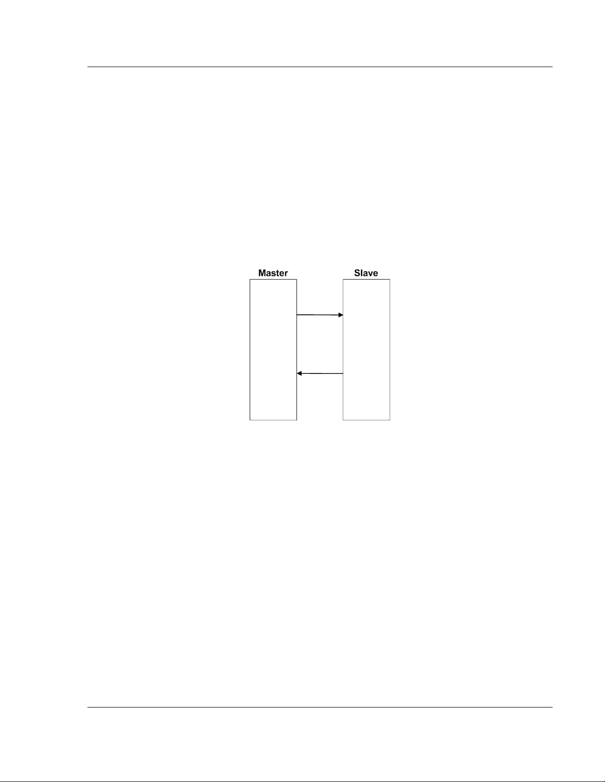
IEC-101 Slave ♦ ProLinx Communication Gateway Reference
IEC 60870-5-101 v3 Slave (Firmware version 3.xx) Protocol Manual
5.2 IEC-60870-5-101 Slave Protocol Implementation
This section presents an overview of how the 101S works, while skipping the
complex details of the protocol specification. If you require more information
about the implementation of the protocol, refer to the protocol specification (IEC
60870-5-101 2003). For more information on configuring and modifying the
implementation of the protocol with the 101S, refer to Configure the Module.
(page 23)
The IEC-60870-5-101 protocol applies to telecontrol equipment and systems with
coded bit serial data transmission for monitoring and controlling geographically
widespread processes.
Any application using the IEC-60870-5-101 protocol will have one Master
(controlling station) and one or more slaves (controlled stations). The Master will
constantly monitor and control the data from each slave in the network.
The gateway works as an IEC-60870-5-101 slave. It can send monitor data,
receive commands or generate events to the Master unit, as explained in the
following topics.
ProSoft Technology, Inc. Page 67 of 159
August 6, 2010
Page 68

Reference IEC-101 Slave ♦ ProLinx Communication Gateway
Protocol Manual IEC 60870-5-101 v3 Slave (Firmware version 3.xx)
5.2.1 Data Flow Between the gateway and External Host
The following section describes the flow of data between the 101S gateway and
the IEC 60870-5-101 Master unit.
Slave Driver
The slave driver allows the 101S gateway to respond to data read and write
commands issued by a Master unit on the serial network. The following flow chart
and associated table describe the flow of data into and out of the gateway.
1 The slave driver receives the configuration information from the configuration
file in the gateway. This information configures the driver and defines the
node characteristics.
2 A host device issues read or write commands to the gateway's node address.
The driver qualifies the message before accepting it into the gateway.
3 Once the gateway accepts the message, the data is immediately transferred
to or from the internal database in the gateway. If the command is a read
command, the data is read out of the database and a response message is
built. If the command is a write command, the data is written directly into the
database and a response message is built. The gateway will also generate
messages without being queried by the host. These messages include
spontaneous and cyclic COT messages.
4 Once the data processing is complete, the response is issued to the
originating Master node.
5 Counters are available in the Status Block that permits the level of activity of
the driver to be determined.
The configuration section of this manual describes the complete list of
parameters that must be defined for a slave. The IEC-60870-5-101
Interoperability Document for the 101S slave contains a listing of the protocol
support supplied by the gateway.
Page 68 of 159 ProSoft Technology, Inc.
August 6, 2010
Page 69

IEC-101 Slave ♦ ProLinx Communication Gateway Reference
IEC 60870-5-101 v3 Slave (Firmware version 3.xx) Protocol Manual
Databases
The read and write areas can be placed anywhere in the gateway's database
area. Because each point is defined individually to the gateway, the data for a
specific type need not be contiguous in the gateway's database. This means that
the gateway error/status area can be passed to the controlling station using the
M_ME_NB_1 database. In the database definition for this type, establish a
M_ME_NB_1 information object for each status value to be monitored by the
controlling station and use the gateway's status database as the DB Address.
This section discusses the databases utilized by the gateway to support the IEC
60870-5-101 protocol. The user is responsible for defining the databases for their
specific application. The size of each ASDU database and definition of each
point within each data type is established in the gateway’s configuration file or by
using ProSoft Configuration Builder. Refer to the Module Configuration section
for a complete discussion of configuration options. The following table
summarizes the ASDU data types used in each of the15 individual databases.
Type ID Type Description Data Representation
1 M_SP_NA_1 Monitored Single-point Information: This data
type stores a single binary input point.
Associated time-tagged event information for
this type are M_SP_TA_1 (2) and M_SP_TB_1
(30).
3 M_DP_NA_1 Monitored Double-point Information: This data
type stores a dual-point binary input value
(that is, valve status). Associated time-tagged
event information for this type are
M_DP_TA_1 (4) and M_DP_TB_1 (31).
5 M_ST_NA_1 Monitored Step-point Information: This data
type is used for step position of transformers
or other step position information. The value
for the position ranges from -64 to 63.
Associated time-tagged event information for
this type are M_ST_TA_1 (6) and M_ST_TB_1
(32).
7 M_BO_NA_1 Monitored 32-Bit Bitstring Binary State
Information: This data type is used to hold and
transmit binary state data as bitstrings of 32
bits.
9 M_ME_TA_1 Monitored Normalized Measured Value: This
data type is used for analog input data.
Associated time-tagged event information for
this type are M_ME_TA_1 (10) and
M_ME_TD_1 (34).
11 M_ME_NB_1 Monitored Scaled Measured Value: This data
type is used for analog input data. Associated
time-tagged event information for this type are
M_ME_TB_1 (12) and M_ME_TE_1 (35).
Single bit value with 0=Off and 1=On.
Double-bit status with 00b (0 decimal) =
indeterminate or intermediate, 01b (1
decimal) = Off, 10b (2 decimal) = On and
11b (3 decimal) = indeterminate.
Step data is stored in a single character
value with bits 0 to 6 (-64 to +63)
representing the step position and bit 7
representing the following states: 0 =
Equipment is not in transient state 1 =
Equipment in transient state
Bitstring data is stored as groups of 32
bits, with each bit representing the state of
an object: 0=Off and 1=On
Normalized values are stored in a (16-bit)
word data area with a range of -1..+1-2
Scaled values are stored in a (16-bit) word
data area with a range of -2
15.. +215
-15
-1
ProSoft Technology, Inc. Page 69 of 159
August 6, 2010
Page 70

Reference IEC-101 Slave ♦ ProLinx Communication Gateway
Protocol Manual IEC 60870-5-101 v3 Slave (Firmware version 3.xx)
Type ID Type Description Data Representation
13 M_ME_NC_1 Monitored Measured Value, Short Floating-
Point Number: This data type is used for
analog input data stored in floating point
format according to the IEEE STD 754, QDS
format. Associated time-tagged event
information for this type are M_ME_TC_1 (14)
and M_ME_TE_1 (36).
15 M_IT_NA_1 Monitored Integrated Total-point Information:
This data type stores meter or other count
data. Associated time-tagged event
information for this type are M_IT_TA_1 (15)
and M_IT_TB_1 (37).
45 C_SC_NA_1 Single-point Command: This command
controls a single binary point such as a relay.
46 C_DC_NA_1 Double-point Command: This command
controls a dual-point binary control device
such as a trip/close relay.
47 C_RC_NA_1 Regulating Step Command: This command
controls a stepping device such as a
transformer.
48 C_SE_NA_1 Setpoint Command, Normalized Value: This
command controls an analog device.
49 C_SE_NB_1 Setpoint Command, Scaled Value: This
command controls an analog device.
50 C_SE_NC_1 Setpoint Command, Short Floating-Point
Value: This data type is used for analog input
data stored in floating point format according
to the IEEE STD 754, QDS format.
51 C_BO_NA_1 32-Bit Bitstring Binary State Command: This
data type is used to hold and transmit binary
state data as bitstrings of 32 bits.
Short floating-point number stored in IEEE
STD 754 format (Fraction, Exponent, Sign)
Binary counter data is stored in a doubleword (32-bit) value with a range of -
31
2
..+231-1.
Single bit value with 0 = Off and 1 = On
Double Command with 0 = Not permitted 1
= Off 2 = On 3 = Not permitted
Regulating Step Command with 0 = Not
permitted 1 = Next step lower 2 = Next
step higher 3 = Not permitted
Normalized values are stored in a (16-bit)
word data area with a range of -1..+1-2
Scaled values are stored in a (16-bit) word
data area with a range of -2
Short floating-point number stored in IEEE
STD 754 format (Fraction, Exponent, Sign)
Bitstring data is stored as groups of 32
bits, with each bit representing the state of
an object: 0=Off and 1=On
15.. +215
-15
-1
A key concept in interfacing the protocol with the internal database is the
relationship between the IEC-60870-5-101 databases and the data transfer
operation between the driver and gateway's internal database. The control data
types, C_XX_XX_1, are transferred from the driver to the gateway's internal
database. This data can then be used by the other gateway protocol or processor
in which the gateway is installed to control other devices. The monitor data types
(M_XX_XX_1) are sourced from the gateway's internal database and is
transferred to the remote Master on the IEC-60870-5-101 network.
Page 70 of 159 ProSoft Technology, Inc.
August 6, 2010
Page 71

IEC-101 Slave ♦ ProLinx Communication Gateway Reference
IEC 60870-5-101 v3 Slave (Firmware version 3.xx) Protocol Manual
The relationships between the data types and the read and write data areas of
thegateway are displayed in the following diagram:
The Write Data Area is used to hold data for the 101S Monitored Point
databases, which is data that will be sent by the 101S Slave driver from the
gateway to the remote Master. The Read Data Area is used to hold data for the
101S Control Point databases, which is data that has been sent from the remote
Master to the 101S driver to be stored in the gateway. The read and write areas
can be placed anywhere in the gateway's database. Because the gateway
address of each point is defined individually, the data area for a specific data
type need not be contiguous in the gateway’s memory. However, most users find
it convenient to keep data of each type in contiguous address blocks.
Module error/status data can be passed to the Master using the M_ME_NB_1
database. In the database definition for the type, establish a point for each status
value to be monitored by the Master and set the gateway's database address for
the point in the definition.
ProSoft Technology, Inc. Page 71 of 159
August 6, 2010
Page 72

Reference IEC-101 Slave ♦ ProLinx Communication Gateway
Protocol Manual IEC 60870-5-101 v3 Slave (Firmware version 3.xx)
5.2.2 General Parameter Configuration
Communication Parameters
The following parameters should be configured for serial communication:
Adjust these parameters for your application.
Page 72 of 159 ProSoft Technology, Inc.
August 6, 2010
Page 73

IEC-101 Slave ♦ ProLinx Communication Gateway Reference
IEC 60870-5-101 v3 Slave (Firmware version 3.xx) Protocol Manual
Data Link Configuration
The protocol specification document IEC 60870-5-2 specifies an unambiguous
address (number) must be used for each link. Each address may be unique
within a specific system, or may be unique within a group of links sharing a
common channel. The protocol specification defines that the Data Link Address
may have 0, 1 or 2 octets. The first option should be used only during Balanced
Mode.
Configure the Data Link Address Length parameter to set the number of octets to
be used for the Data Link Address value. It is essential that the Master unit also
uses the same number of octets configured in the 101 Slave. Values shown here
are for example only. Your application may require different settings.
Data Link Address Length: 1
You must also configure the actual Data Link Address value using the following
parameter:
Data link address: 1
This value identifies the gateway’s address in the network.
ProSoft Technology, Inc. Page 73 of 159
August 6, 2010
Page 74

Reference IEC-101 Slave ♦ ProLinx Communication Gateway
Protocol Manual IEC 60870-5-101 v3 Slave (Firmware version 3.xx)
ASDU Configuration
The protocol specification document IEC 60870-5-3 describes the Basic
Application Data Units that are used in the protocol. It also defines the
Application Service Data Unit (ASDU) used by the protocol for data
communication.
You can configure the number of bytes to be used for the following ASDU
components:
Component Abbreviation Possible Number of Octets
Cause of Transmission COT 1 or 2
Common Address of ASDU CASDU 1 or 2
Information Object Address IOA 1, 2 or 3
These parameters must be configured to match the Master's configuration
(values shown are for example only; your application may require different
values):
The Common Address of ASDU is the station address. The gateway allows the
addressing of only the whole station (some devices allows different Common
Addresses to identify particular station sectors). You should configure the
Common ASDU Address with the following parameter:
Common Address of ASDU: 1
You should also configure the maximum number of bytes that the gateway will
support for each ASDU response to the Master unit. The range is from 25 to 252
bytes. You should verify the maximum number of bytes supported by the Master
because some IEC 60870-5-101 Master devices support messages with less
than 252 bytes.
Configure the following parameter to set the maximum number of bytes to be
transferred at every ASDU response.
Maximum ASDU Resp Len: 252
A value less than 252 can cause the gateway to break down the response to
send all points using more response messages, with each message containing
fewer bytes.
Page 74 of 159 ProSoft Technology, Inc.
August 6, 2010
Page 75

IEC-101 Slave ♦ ProLinx Communication Gateway Reference
IEC 60870-5-101 v3 Slave (Firmware version 3.xx) Protocol Manual
Example - Changing the ASDU Length:
Considering that the Master sends a General Interrogation request to poll forty
M_ME_NB points (measured scaled points in Unbalanced Mode):
If Maximum ASDU Resp Len = 252:
ProSoft Technology, Inc. Page 75 of 159
August 6, 2010
Page 76

Reference IEC-101 Slave ♦ ProLinx Communication Gateway
Protocol Manual IEC 60870-5-101 v3 Slave (Firmware version 3.xx)
This example shows that the gateway sends all 40 measured scaled points in
one single message, if the message is not greater than 252 bytes. However,
some Master devices may not support messages containing this number of
bytes. If the Master for a given application supports only 100 bytes, the following
communication procedure would occur:
As shown in the previous diagram, the gateway sends out three (3) messages
(15 points, 15 points, and 10 points) instead of sending the whole 40 points in
one single message.
Note: This example shows the case where IOA Length = 3 bytes, COT Length = 2 bytes and
CASDU Length = 2 bytes.
Important: If the database parser gets a point index that is not valid, the whole database is set as
invalid and no points are reported. Because the index 0 is not valid (the protocol does not support
this index value), the driver considers it invalid. For example, if you set the size of the ASDU to 1
and you set a value of 1000 for a point index, this is also invalid as the indexes can only go from 1
to 255.
Page 76 of 159 ProSoft Technology, Inc.
August 6, 2010
Page 77

IEC-101 Slave ♦ ProLinx Communication Gateway Reference
IEC 60870-5-101 v3 Slave (Firmware version 3.xx) Protocol Manual
Balanced and Unbalanced Modes
The gateway supports balanced and unbalanced modes. In balanced mode,
each station may initiate message transfers. If the links from the Master unit to
several slaves share a common physical channel, then these links must be
operated in an unbalanced mode to avoid the possibility of more than one device
attempting to transmit on the channel at the same time.
Select the communication mode with the following parameter:
To use balanced mode, configure the following parameters:
ProSoft Technology, Inc. Page 77 of 159
August 6, 2010
Page 78

Reference IEC-101 Slave ♦ ProLinx Communication Gateway
Protocol Manual IEC 60870-5-101 v3 Slave (Firmware version 3.xx)
Unbalanced mode
In order to start communications between the Master and the slave units, the
Master tries to establish the link connection by transmitting repeated "Request
Status of Link" at specific time out intervals. When the gateway’s link is available,
it will respond with a "Status of Link" response. Then, the Master transmits a
"Reset of Remote Link" message and the slave responds with an Acknowledge
(ACK) response. Then the Master sends two consecutive Class 1 requests. The
slave responds the first Class 1 request with an "End of Initialization" response
and the second Class 1 request with an ACK message.
The following illustration shows a typical initialization procedure for the
unbalanced mode:
Page 78 of 159 ProSoft Technology, Inc.
August 6, 2010
Page 79

IEC-101 Slave ♦ ProLinx Communication Gateway Reference
IEC 60870-5-101 v3 Slave (Firmware version 3.xx) Protocol Manual
Balanced Mode
During balanced mode, the link must be initialized in both directions. The 101S
gateway also always reinitializes the link after it receives an initialization request
from the Master. Therefore, the following initialization occurs during balanced
mode, after 101S boots.
After the initialization procedure is completed, the Master and the 101S start
communicating. During communication, if the Master fails to respond to a
message from the gateway, the gateway will retry for a configured number of
times. If the Master still fails to respond, the gateway will attempt to initialize the
line again.
ProSoft Technology, Inc. Page 79 of 159
August 6, 2010
Page 80

Reference IEC-101 Slave ♦ ProLinx Communication Gateway
Protocol Manual IEC 60870-5-101 v3 Slave (Firmware version 3.xx)
5.2.3 Monitor Direction and Control Direction
The protocol specification defines two directions of data: monitor direction and
control direction.
Monitor Direction: The direction of transmission from a slave to the Master
Control Direction: The direction of transmission from the Master to the slave
The points that are typically transferred from the slave to the Master are also
known as Monitor Points (or Monitor Information Objects). The points that are
typically transferred from the Master to the slave are also known as Control
Points (or Command Information Objects).
The following illustration describes the data transfer for control and monitor
points between the 101S and the Master.
You must configure all points in the correct location in the 101S gateway
database, so that they can be updated properly from the Master.
Page 80 of 159 ProSoft Technology, Inc.
August 6, 2010
Page 81

IEC-101 Slave ♦ ProLinx Communication Gateway Reference
IEC 60870-5-101 v3 Slave (Firmware version 3.xx) Protocol Manual
5.2.4 Using Monitor Points
The following monitor points are supported by the 101S gateway:
Symbol Description Data Size in
Database
M_SP_NA Monitored Single-Points 1 bit Bit
M_DP_NA Monitored Dual-Points 2 bits Bit
M_ST_NA Monitored Step-Points 1 byte Byte
M_ME_NA Monitored Measured Normalized-Points 1 word Word
M_BO_NA Monitored 32-bit Bitstring Points 2 words Word
M_ME_NB Monitored Measured Scaled-Points 1 word Word
M_ME_NC Monitored Measured Short Floating Points 2 words Double-Word
M_IT_NA Monitored Counter-Points 2 words Double-Word
Each monitor point is identified by its Information Object Address (it should be
unique for each Common ASDU Address in the network). For each monitor point,
configure the following parameters:
Point # - The information object address of the point. It identifies the point in the
network.
DB Address - The database location in the 101S gateway associated with the
point. You must associate each point to a database address in the 101S
gateway. The interpretation of this parameter depends on the point type
configured. For example, for an M_SP_NA point, this value represents the bit
address. For a M_ME_NA point, this value represents the Word address.
Group(s) - This is the group definition for the point. It sets how the point will be
polled by the Master (cyclic or group interrogation). It can also be used to enable
or disable the event generation for one specific point. The group parameter is
discussed in the Data Communication section.
Deadband - Sets the deadband for each Measured point. If the value changes
from more than the configured deadband , the gateway will generate an event for
this point.
IV DB Bit - This feature allows the application to set the invalid (IV) quality bit of
the protocol for all the monitored ASDU types supported. If you enable this
feature, the Master can determine the individual IV quality bit status of each point
you configured.
Addressing
Type
ProSoft Technology, Inc. Page 81 of 159
August 6, 2010
Page 82
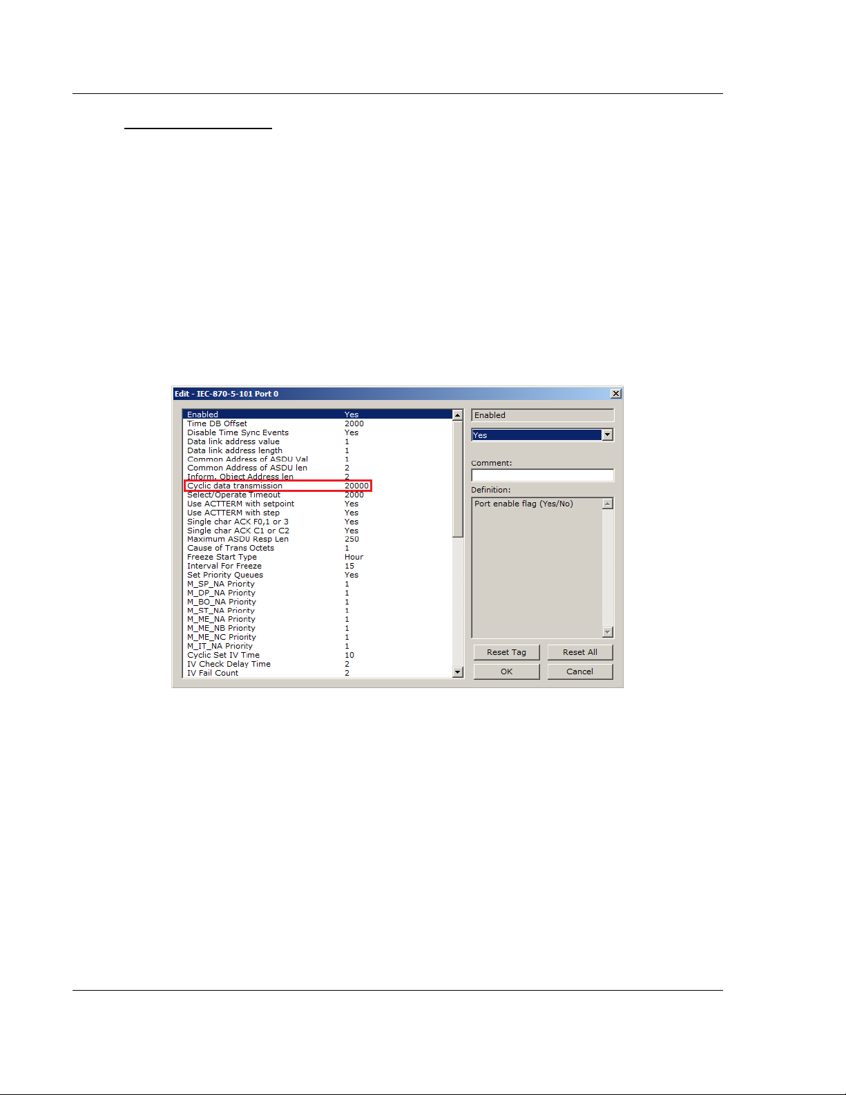
Reference IEC-101 Slave ♦ ProLinx Communication Gateway
Protocol Manual IEC 60870-5-101 v3 Slave (Firmware version 3.xx)
Monitor Data Transfer
In unbalanced mode, the polling procedure is initiated from the Master unit
through Class 1 and Class 2 requests. In general, ASDUs containing
periodic(cyclic) causes of transmission are typically assigned to be transmitted in
response to Class 2 requests from the Master. All ASDUs containing time-tagged
or spontaneous causes of transmission are typically assigned to be transmitted in
response to Class 1 requests. Other ASDUs with other causes of transmission of
low priority, such as background scans, may also be assigned to be transmitted
in response to Class 2 requests.
Typically, you should properly configure the group code (page 50) for each
monitor point to define how the Master will poll for the point.
The gateway will periodically send all points configured for periodic/cyclic poll
(0x80000000) at every x milliseconds, where x is configured with the Cyclic Data
Transmission parameter:
Page 82 of 159 ProSoft Technology, Inc.
August 6, 2010
Page 83

IEC-101 Slave ♦ ProLinx Communication Gateway Reference
IEC 60870-5-101 v3 Slave (Firmware version 3.xx) Protocol Manual
M_SP_NA
A Monitor Single-Point information object occupies one binary bit and uses bit
addressing. For example, if you configured the following points as shown:
The following table describes how these points would be stored in the gateway:
Inf. Object Address Module Database Address
100 Bit 0 of word 100 (Bit address 1600)
101 Bit 1 of word 100 (Bit address 1601)
102 Bit 2 of word 100 (Bit address 1602)
ProSoft Technology, Inc. Page 83 of 159
August 6, 2010
Page 84

Reference IEC-101 Slave ♦ ProLinx Communication Gateway
Protocol Manual IEC 60870-5-101 v3 Slave (Firmware version 3.xx)
M_ST_NA
A Monitor Step Position information object occupies one byte and uses byte
addressing.
For example, if you configured the following points:
The following table describes how these points would be stored in the gateway.
Inf. Object Address Module Database Address
300 Low byte of word 20 (Byte address 40)
301 Low byte of word 30 (Byte address 60)
302 High byte of word 40 (Byte address 81)
Page 84 of 159 ProSoft Technology, Inc.
August 6, 2010
Page 85

IEC-101 Slave ♦ ProLinx Communication Gateway Reference
IEC 60870-5-101 v3 Slave (Firmware version 3.xx) Protocol Manual
M_BO_NA
A Monitored 32-Bit Bitstring Point occupies two words and uses double-word
addressing.
For example, if you configured the following points:
The following table describes how these points would be stored in the gateway
memory database.
Inf. Object Address Module Database Address
600 Words 2000 and 2001 (Double-word address 1000)
601 Words 2002 and 2003 (Double-word address 1001)
602 Words 2004 and 2005 (Double-word address 1002)
ProSoft Technology, Inc. Page 85 of 159
August 6, 2010
Page 86

Reference IEC-101 Slave ♦ ProLinx Communication Gateway
Bit
15
14
13
12
11
10 9 8 7 6 5 4 3 2 1 0
4000h
3210h
Protocol Manual IEC 60870-5-101 v3 Slave (Firmware version 3.xx)
M_ME_NA and M_ME_NB
A Monitor Normalized Measured information object or Monitor Scaled Measured
information object occupies one word and uses word addressing.
For example, if you configured the following points:
The following table describes how these points would be stored in the gateway.
Inf. Object Address Module Database Address
400 Word 10 (Word address 10)
401 Word 12 (Word address 12)
402 Word 18 (Word address 18)
Monitor Normalized Measured information objects use a data representation
defined by the protocol specification to represent fractional decimal values. The
following table describes the value for each bit as a reciprocal power of two (2),
that is two (2) raised to the power of a negative exponent (-1 through -15). Bit 15
is the Sign Bit.
Value
Hex(h)
Decimal
0.5
2000h
0.25
1000h
0.125
6000h
0.75
0.395751953125
800
400
200
100
80
40
h
h
-8
-9
2
2
Sign
4000h
-1
2
2000h
2-2
1000h
2-3
h
h
h
-4
-5
2
2
h
-6
-7
2
2
0 1 0 0 0 0 0 0 0 0 0 0 0 0 0 0
0 0 1 0 0 0 0 0 0 0 0 0 0 0 0 0
0 0 0 1 0 0 0 0 0 0 0 0 0 0 0 0
0 1 1 0 0 0 0 0 0 0 0 0 0 0 0 0
0 0 1 1 0 0 1 0 0 0 0 1 0 0 0 0
10
20
h
h
-10
-11
2
2
4h
8h
-12
-13
2
2
1h
2h
-14
-15
2
2
Page 86 of 159 ProSoft Technology, Inc.
August 6, 2010
Page 87

IEC-101 Slave ♦ ProLinx Communication Gateway Reference
IEC 60870-5-101 v3 Slave (Firmware version 3.xx) Protocol Manual
Examples:
A value of 4000hex (only Bit 14 set, all others clear) is interpreted as 0.5 decimal
A value of 2000hex (only Bit 13 set, all others clear) is interpreted as 0.25
decimal
A value of 1000hex (only Bit 12 set, all others clear) is interpreted as 0.125
decimal
... and so on until...
A value of 0001hex (Only Bit 0 set, all others clear) is interpreted as
0.000030517578125
Therefore, the actual data values transmitted may be any combination of the
decimal values for any given bit pattern.
M_ME_NC and M_IT_NA The Monitor Short Floating-Point Measured Value and Monitored Integrated
Totals information objects occupy two words with double-word addressing.
For example, if you configured the following points:
The following table describes how these points would be stored in the gateway.
Inf. Object Address Module Database Address
500 Words 40 and 41 (Double-word address 20)
501 Words 64 and 65 (Double-word address 32)
502 Word 104 and 105 (Double-word address 52)
ProSoft Technology, Inc. Page 87 of 159
August 6, 2010
Page 88

Reference IEC-101 Slave ♦ ProLinx Communication Gateway
Protocol Manual IEC 60870-5-101 v3 Slave (Firmware version 3.xx)
5.2.5 Using Control (Command) Points
The 101S gateway supports the following Control points:
ASDU Type Information Object Description
C_SC_NA Control Single Command
C_DC_NA Control Double Command
C_RC_NA Control Regulating Step Command
C_BO_NA Control 32-Bit Bitstring Command
C_SE_NA Control Normalized Value Set Point Command
C_SE_NB Control Scaled Value Set Point Command
C_SE_NC Control Short Floating-Point Value Set Point Command
Each Control point is identified by its Information Object Address. For each
Control point, configure the following parameters:
Point # - This is the Information Object Address of the point. It identifies the point
in the network. This address must be unique for each Common ASDU Address in
the network.
DB Address - This is the database location in the 101S gateway associated with
the point.
Monitor Point # - This is the Information Object Address of the associated
Monitor point to be sent to the Client once the Control request is received.
Monitor DB Address - The user might (optionally) configure a Monitor point to be
sent by the 101S gateway when it receives the command for that specific point.
Require Select - This parameter configures the point to require a Select request
before the Operate command.
Page 88 of 159 ProSoft Technology, Inc.
August 6, 2010
Page 89

IEC-101 Slave ♦ ProLinx Communication Gateway Reference
IEC 60870-5-101 v3 Slave (Firmware version 3.xx) Protocol Manual
Example (C_SC_NA)
In the example above, each time the gateway receives a value of one (1) in
Control Single Command 700, it will send a response by placing a value of one
(1) in Monitor Single-Point # 100 at database bit address 1600.
Some of the Command points may be configured to require a Select command
before they will act on an Execute command.
ProSoft Technology, Inc. Page 89 of 159
August 6, 2010
Page 90

Reference IEC-101 Slave ♦ ProLinx Communication Gateway
Protocol Manual IEC 60870-5-101 v3 Slave (Firmware version 3.xx)
Select/Operate Timeout Parameter
Use the Select/Operate Timeout parameter to configure the select/operate
timeout period. After the gateway receives the Select command, it will wait for
this period of time to receive the Execute command for the same point address. If
the gateway does not receive an Execute command within this period of time, it
will require another Select operation before the Execute operation will be
accepted and acted upon.
Page 90 of 159 ProSoft Technology, Inc.
August 6, 2010
Page 91

IEC-101 Slave ♦ ProLinx Communication Gateway Reference
IEC 60870-5-101 v3 Slave (Firmware version 3.xx) Protocol Manual
Control Data Transfer
The control communication typically occurs when the Master sends a command
request to update the gateway’s command points.
The following illustration shows a typical command communication between the
Master and gateway during unbalanced operation.
Some of the command points may be configured to be selected before executed.
The following illustration shows a typical command communication between the
Master and gateway operation with a SELECT operation.
ProSoft Technology, Inc. Page 91 of 159
August 6, 2010
Page 92

Reference IEC-101 Slave ♦ ProLinx Communication Gateway
Protocol Manual IEC 60870-5-101 v3 Slave (Firmware version 3.xx)
Refer to the following parameter to configure the select/operate timeout period.
After the gateway receives the SELECT operation it will wait for this period of
time for the EXECUTE operation. If the gateway does not receive an EXECUTE
operation within this period of time it will require another SELECT operation
before the EXECUTE operation.
Page 92 of 159 ProSoft Technology, Inc.
August 6, 2010
Page 93

IEC-101 Slave ♦ ProLinx Communication Gateway Reference
IEC 60870-5-101 v3 Slave (Firmware version 3.xx) Protocol Manual
Control Points Addressing
Control points must be configured in a database area that is updated in the
gateway. You must associate each point to a database address in the 101S
gateway. The interpretation of the DB Address parameter in the configuration
tables depends on the point type configured and the type of addressing
associated with that point type.
ASDU Type Data Size Addressing Type
C_SC_NA 1 bit Bit
C_DC_NA 2 bits Bit
C_RC_NA 1 byte Byte
C_BO_NA 2 words Double word
C_SE_NA 1 word Word
C_SE_NB 1 word Word
C_SE_NC 2 words Double word
ProSoft Technology, Inc. Page 93 of 159
August 6, 2010
Page 94

Reference IEC-101 Slave ♦ ProLinx Communication Gateway
Protocol Manual IEC 60870-5-101 v3 Slave (Firmware version 3.xx)
C_SC_NA and C_DC_NA
The single-point command and dual-point command points use one bit with bitaddressing. For example, if you configure the following points:
The following table describes how these points would be used.
Inf. Object Address Module Database Address
100 Bit 0 of word 100
101 Bit 1 of word 100
102 Bit 2 of word 100
The protocol specification defines a qualifier value that is set by the Master to
determine the duration of the pulse (short, long or persistent). Configure the
Short Pulse Time and Long Pulse Time parameters, seen below, to set the
duration of the short and long pulses:
Page 94 of 159 ProSoft Technology, Inc.
August 6, 2010
Page 95

IEC-101 Slave ♦ ProLinx Communication Gateway Reference
IEC 60870-5-101 v3 Slave (Firmware version 3.xx) Protocol Manual
C_RC_NA
A Control Regulating Step Command information object occupies one byte and
uses byte addressing.
For example, if you configured the following points:
The following table describes how these points would be used.
Inf. Object Address Module Database Address
1000 Low Byte of word 250 (Byte address 500)
300 Low Byte of word 20 (Byte address 40. Must match
configuration of point 300 in M_ST_NA.)
1001 Low Byte of word 260 (Byte address 520)
301 Low Byte of word 30 (Byte address 60. Must match
configuration of point 301 in M_ST_NA.)
1002 High Byte of word 270 (Byte address 541)
302 High Byte of word 40 (Byte address 81. Must match
configuration of point 302 in M_ST_NA.)
ProSoft Technology, Inc. Page 95 of 159
August 6, 2010
Page 96

Reference IEC-101 Slave ♦ ProLinx Communication Gateway
Protocol Manual IEC 60870-5-101 v3 Slave (Firmware version 3.xx)
C_BO_NA
A Control 32-Bit Bitstring Command information object occupies two words and
uses double-word addressing.
For example, if you configured the following points:
These points would be used as follows:
Inf. Object Address Module Database Address
3100 Words 3000 and 3001 (Double-word address 1500)
600 Words 2000 and 2001(Double-word address 1000. Must
match the configuration of point 600 in M_BO_NA.)
3101 Words 3002 and 3003 (Double-word address 1501)
601 Words 2002 and 2001 (Double-word address 1001. Must
match the configuration of point 601 in M_BO_NA.)
3102 Words 3003 and 3004 (Double-word address 1502)
602 Words 2004 and 2005 (Double-word address 1002. Must
match the configuration of point 602 in M_BO_NA.)
Page 96 of 159 ProSoft Technology, Inc.
August 6, 2010
Page 97

IEC-101 Slave ♦ ProLinx Communication Gateway Reference
Inf. Object Address
Module Database Address
4000h
2000h
1000h
IEC 60870-5-101 v3 Slave (Firmware version 3.xx) Protocol Manual
C_SE_NA and C_SE_NB
The Control Normalized Value Set Point Command information object and the
Control Scaled Value Set Point Command information object use one word with
word addressing. For example, if you configured the following points:
The following table describes how these points would be used.
1100 Word 2000 (Word address 2000)
400 Word 10 (Word address 10. Must match the
configuration of point 400 in M_ME_NA.)
1101 Word 2001 (Word address 2001)
401 Word 12 (Word address 12. Must match the
configuration of point 401 in M_ME_NA.)
1102 Word 2002 (Word address 2002)
402 Word 18 (Word address 18. Must match the
configuration of point 402 in M_ME_NA.)
The Control Normalized Measured information objects use a data representation
defined by the protocol specification to represent fractional decimal values. The
following table describes the value for each bit as a reciprocal power of two (2),
that is two (2) raised to the power of a negative exponent (-1 through -15). Bit 15
is the Sign Bit.
Bit 15 14 13 12 11 10 9 8 7 6 5 4 3 2 1 0
Value
Hex(h)
Decimal
0.5
0.25
0.125
6000h
0.75
3210h
0.395751953125
400
200
100
80
Sign
4000h
2-1
2000h
2-2
1000h
2-3
800
h
-4
2
h
h
h
2-5
2-6
2-7
h
2-8
40
h
2-9
0 1 0 0 0 0 0 0 0 0 0 0 0 0 0 0
0 0 1 0 0 0 0 0 0 0 0 0 0 0 0 0
0 0 0 1 0 0 0 0 0 0 0 0 0 0 0 0
0 1 1 0 0 0 0 0 0 0 0 0 0 0 0 0
0 0 1 1 0 0 1 0 0 0 0 1 0 0 0 0
20
h
2
10
h
-10
-11
2
4h
8h
-12
-13
2
2
1h
2h
-14
-15
2
2
ProSoft Technology, Inc. Page 97 of 159
August 6, 2010
Page 98

Reference IEC-101 Slave ♦ ProLinx Communication Gateway
Protocol Manual IEC 60870-5-101 v3 Slave (Firmware version 3.xx)
Examples:
A value of 4000hex (only Bit 14 set, all others clear) is interpreted as 0.5 decimal
A value of 2000hex (only Bit 13 set, all others clear) is interpreted as 0.25
decimal
A value of 1000hex (only Bit 12 set, all others clear) is interpreted as 0.125
decimal
... and so on until...
A value of 0001hex (Only Bit 0 set, all others clear) is interpreted as
0.000030517578125
Therefore, the actual data values transmitted may be any combination of the
decimal values for any given bit pattern.
C_SE_NC
The measured short floating point command uses two words with double-word
addressing. For example, if you configured the following points:
The following table describes how these points would be used.
Inf. Object Address 101S v3 gateway Database Address
400 Words 5 and 6
401 Words 6 and 7
402 Words 9 and 10
Page 98 of 159 ProSoft Technology, Inc.
August 6, 2010
Page 99

IEC-101 Slave ♦ ProLinx Communication Gateway Reference
IEC 60870-5-101 v3 Slave (Firmware version 3.xx) Protocol Manual
5.2.6 Events
In order to improve the communication efficiency, most applications will require
the Master to periodically poll for data changes with a higher priority than polling
for monitor data. Every time data change occurs, the slave should send this
information, typically with the date and time information on when the data change
occurred.
The following illustration shows the event communication between the Master
and the gateway during unbalanced mode:
The gateway can queue up to 99 events per data type. When the queue is full,
the oldest event will be deleted each time a new event is added to the queue.
You must configure the Master to poll the event queue frequently enough to
avoid losing events.
ProSoft Technology, Inc. Page 99 of 159
August 6, 2010
Page 100

Reference IEC-101 Slave ♦ ProLinx Communication Gateway
Protocol Manual IEC 60870-5-101 v3 Slave (Firmware version 3.xx)
The events can be returned for Class 1 or Class 2 requests according to the data
type as follows:
Data Type Class Request
M_SP_NA Class 1
M_DP_NA Class 1
M_ST_NA Class 1
M_BO_NA Class 1
M_ME_NA Class 2
M_ME_NB Class 2
M_ME_NC Class 2
M_IT_NA Class 1
Note: In response to a Class 2 poll the gateway may respond with Class 1 data when there is no
Class 2 data available. So eventually the events for M_SP_NA, M_DP_NA and M_ST_NA points
may also be sent during a Class 2 response.
Deadbands
The Monitored Measured points (M_ME_NA and M_ME_NB) will generate
events only if the data value changes an amount greater than or equal to the
configured deadband value.
For example, if the following point is configured:
Then, if the current value for this point is 130, it would generate events only if:
NEW VALUE is less than or equal to 30
OR
NEW VALUE is greater than or equal to 230.
Each monitored measured point can have its own deadband value assigned to it
in the configuration file or by using the PCB configuration options.
Page 100 of 159 ProSoft Technology, Inc.
August 6, 2010
 Loading...