

Page 1
ProLinx DNPS
ProLinx Gateway
DNP 3.0 Slave
December 01, 2009
USER MANUAL
Page 2

Important Installation Instructions
Power, Input, and Output (I/O) wiring must be in accordance with Class I, Division 2 wiring methods, Article 501-4 (b)
of the National Electrical Code, NFPA 70 for installation in the U.S., or as specified in Section 18-1J2 of the Canadian
Electrical Code for installations in Canada, and in accordance with the authority having jurisdiction. The following
warnings must be heeded:
A WARNING - EXPLOSION HAZARD - SUBSTITUTION OF COMPONENTS MAY IMPAIR SUITABILITY FOR
CLASS I, DIV. 2;
B WARNING - EXPLOSION HAZARD - WHEN IN HAZARDOUS LOCATIONS, TURN OFF POWER BEFORE
REPLACING OR WIRING MODULES
C WARNING - EXPLOSION HAZARD - DO NOT DISCONNECT EQUIPMENT UNLESS POWER HAS BEEN
SWITCHED OFF OR THE AREA IS KNOWN TO BE NONHAZARDOUS.
D THIS DEVICE SHALL BE POWERED BY CLASS 2 OUTPUTS ONLY.
All ProLinx® Products
WARNING – EXPLOSION HAZARD – DO NOT DISCONNECT EQUIPMENT UNLESS POWER HAS BEEN
SWITCHED OFF OR THE AREA IS KNOWN TO BE NON-HAZARDOUS.
AVERTISSEMENT – RISQUE D'EXPLOSION – AVANT DE DÉCONNECTER L'EQUIPMENT, COUPER LE
COURANT OU S'ASSURER QUE L'EMPLACEMENT EST DÉSIGNÉ NON DANGEREUX.
Markings
UL/cUL ISA 12.12.01 Class I, Div 2 Groups A, B, C, D
cUL C22.2 No. 213-M1987
243333 183151
CL I Div 2 GPs A, B, C, D
Temp Code T5
II 3 G
Ex nA nL IIC T5 X
0° C <= Ta <= 60° C
II – Equipment intended for above ground use (not for use in mines).
3 – Category 3 equipment, investigated for normal operation only.
G – Equipment protected against explosive gasses.
ProLinx Gateways with Ethernet Ports
Series C ProLinx™ Gateways with Ethernet ports do NOT include the HTML Web Server. The HTML Web Server
must be ordered as an option. This option requires a factory-installed hardware addition. The HTML Web Server now
supports:
8 MB file storage for HTML files and associated graphics files (previously limited to 384K)
32K maximum HTML page size (previously limited to 16K)
To upgrade a previously purchased Series C model:
Contact your ProSoft Technology distributor to order the upgrade and obtain a Returned Mercha ndise Authorization
(RMA) to return the unit to ProSoft Technology.
Page 3

To Order a ProLinx Plus gateway with the -WEB option:
Add -WEB to the standard ProLinx part number. For example, 5201-MNET-MCM-WEB.
Your Feedback Please
We always want you to feel that you made the right decision to use our products. If you have suggestions, comments,
compliments or complaints about the product, documentation, or support, please write or call us.
ProSoft Technology
5201 Truxtun Ave., 3rd Floor
Bakersfield, CA 93309
+1 (661) 716-5100
+1 (661) 716-5101 (Fax)
www.prosoft-technology.com
support@prosoft-technology.com
Copyright © ProSoft Technology, Inc. 2009. All Rights Reserved.
ProLinx DNPS User Manual
December 01, 2009
ProSoft Technology
Technology, Inc. All other brand or product names are or may be trademarks of, and are used to identify products
and services of, their respective owners.
®
, ProLinx ®, inRAx ®, ProTalk®, and RadioLinx ® are Registered Trademarks of ProSoft
ProSoft Technology® Product Documentation
In an effort to conserve paper, ProSoft Technology no longer includes printed manuals with our product shipments.
User Manuals, Datasheets, Sample Ladder Files, and Configuration Files are provide d on the enclosed CD-ROM,
and are available at no charge from our web site: www.prosoft-technology.com
Printed documentation is available for purchase. Contact ProSoft Technology for pricing and availability.
North America: +1.661.716.5100
Asia Pacific: +603.7724.2080
Europe, Middle East, Africa: +33 (0) 5.3436.87.20
Latin America: +1.281.298.9109
Page 4

Page 5

Contents ProLinx DNPS ♦ ProLinx Gateway
User Manual DNP 3.0 Slave
Contents
Important Installation Instructions.......................................................................................................2
Your Feedback Please........................................................................................................................3
ProSoft Technology® Product Documentation....................................................................................3
Guide to the ProLinx DNPS User Manual 7
1 Start Here 9
1.1 ProLinx Reference Guide..........................................................................................9
1.2 Install ProSoft Configuration Builder Software..........................................................9
1.3 Using ProSoft Configuration Builder .......................................................................10
1.4 DNPS Protocol Configuration..................................................................................14
1.5 Download the Project to the Module.......................................................................28
2 Diagnostics and Troubleshooting 31
2.1 Requirements..........................................................................................................31
2.2 LED Indicators.........................................................................................................35
2.3 Serial Port DNPS Error and Status Data.................................................................36
3 Reference 41
3.1 Product Specifications.............................................................................................41
3.2 Communication Port Cables....................................................................................44
3.3 Functional Overview................................................................................................50
3.4 DNP Collision Avoidance ........................................................................................64
3.5 IIN Response: Slave Port........................................................................................65
3.6 IIN Bit Definitions.....................................................................................................66
3.7 Event Size Computation..........................................................................................67
3.8 Device Profile..........................................................................................................68
3.9 Subset Definition.....................................................................................................70
4 Support, Service & Warranty 79
4.1 How to Contact Us: Technical Support...................................................................79
4.2 Return Material Authorization (RMA) Policies and Conditions................................80
4.3 LIMITED WARRANTY.............................................................................................81
Index 85
ProSoft Technology, Inc. Page 5 of 86
December 1, 2009
Page 6

ProLinx DNPS ♦ ProLinx Gateway Contents
DNP 3.0 Slave User Manual
Page 6 of 86 ProSoft Technology, Inc.
December 1, 2009
Page 7

Start Here ProLinx DNPS ♦ ProLinx Gateway
User Manual DNP 3.0 Slave
Guide to the ProLinx DNPS User Manual
Function Section to Read Details
Introduction
(Must Do)
Diagnostic and
Troubleshooting
Reference
Product Specifications
Functional Overview
Support, Service, and
Warranty
Index
→
→
→
→
Start Here (page 9)
Diagnostics and
Troubleshooting
(page 31)
Reference (page 41)
Functional Overview
(page 50)
Product
Specifications (page
41)
Support, Service
and Warranty (page
79)
This Section introduces the customer to the
gateway. Included are: package contents,
system requirements, hardware installation, and
basic configuration.
This section describes Diagnostic and
Troubleshooting procedures.
These sections contain general references
associated with this product, Specifications, and
the Functional Overview.
This section contains Support, Service and
Warranty information.
Index of chapters.
ProSoft Technology, Inc. Page 7 of 86
December 1, 2009
Page 8

ProLinx DNPS ♦ ProLinx Gateway Start Here
DNP 3.0 Slave User Manual
Page 8 of 86 ProSoft Technology, Inc.
December 1, 2009
Page 9

Start Here ProLinx DNPS ♦ ProLinx Gateway User Manual DNP 3.0 Slave
1 Start Here
In This Chapter
ProLinx Reference Guide........................................................................9
Install ProSoft Configuration Builder Software.........................................9
Using ProSoft Configuration Builder......................................................10
DNPS Protocol Configuration................................................................14
Download the Project to the Module......................................................28
For most applications, the installation and configuration steps described in this
section will work without additional programming. ProSoft Technology strongly
recommends that you complete the steps in this chapter before developing a
custom application.
1.1 ProLinx Reference Guide
The ProLinx Reference Guide on the ProSoft Solutions CD-ROM provides
detailed information on the entire range of ProLinx modules. If you have any
questions that are not answered in the DNPS User Manual, please refer to the
ProLinx Reference Guide.
1.2 Install ProSoft Configuration Builder Software
You must install the ProSoft Configuration Builder (PCB) software to configure
the gateway. You can always get the newest version of ProSoft Configuration
Builder from the ProSoft Technology web site.
To install ProSoft Configuration Builder from the ProSoft Web Site
1 Open your web browser and navigate to http://www.prosoft-
technology.com/pcb
2 Click the D
Configuration Builder.
3 Choose "S
4 Save the file to your Windows Desktop, so that you can find it easily when
you have finished downloading.
5 When the download is complete, locate and open the file, and then follow the
instructions on your screen to install the program.
OWNLOAD HERE link to download the latest version of ProSoft
AVE" or "SAVE FILE" when prompted.
If you do not have access to the Internet, you can install ProSoft Configuration
Builder from the ProSoft Solutions CD-ROM, included in the package with your
gateway.
ProSoft Technology, Inc. Page 9 of 86
December 1, 2009
Page 10

ProLinx DNPS ♦ ProLinx Gateway Start Here
DNP 3.0 Slave User Manual
To install ProSoft Configuration Builder from the Product CD-ROM
1 Insert the ProSoft Solutions Product CD-ROM into the CD-ROM drive of your
PC. Wait for the startup screen to appear.
2 On the startup screen, click P
RODUCT DOCUMENTATION. This action opens a
Windows Explorer file tree window.
3 Click to open the U
TILITIES folder. This folder contains all of the applications
and files you will need to set up and configure your gateway.
4 Double-click the S
"PCB_*.
EXE" file and follow the instructions on your screen to install the
ETUPCONFIGURATIONTOOL folder, double-click the
software on your PC. The information represented by the "*" character in the
file name is the PCB version number and, therefore, subject to change as
new versions of PCB are released.
Note: Many of the configuration and maintenance procedures use files and other utilities on the
CD-ROM. You may wish to copy the files from the Utilities folder on the CD-ROM to a convenient
location on your hard drive.
1.2.1 Using the Online Help
Most of the information needed to help you use ProSoft Configuration Builder is
provided in a Help System that is always available whenever you are running
ProSoft Configuration Builder. The Help System does not require an Internet
connection.
To view the help pages, start ProSoft Configuration Builder, open the H
menu, and then choose CONTENTS.
1.3 Using ProSoft Configuration Builder
ProSoft Configuration Builder (PCB) provides a quick and easy way to manage
gateway configuration files customized to meet your application needs. PCB is
not only a powerful solution for new configuration files, but also allows you to
import information from previously installed (known working) configurations to
new projects.
ELP
Page 10 of 86 ProSoft Technology, Inc.
December 1, 2009
Page 11
Start Here ProLinx DNPS ♦ ProLinx Gateway
User Manual DNP 3.0 Slave
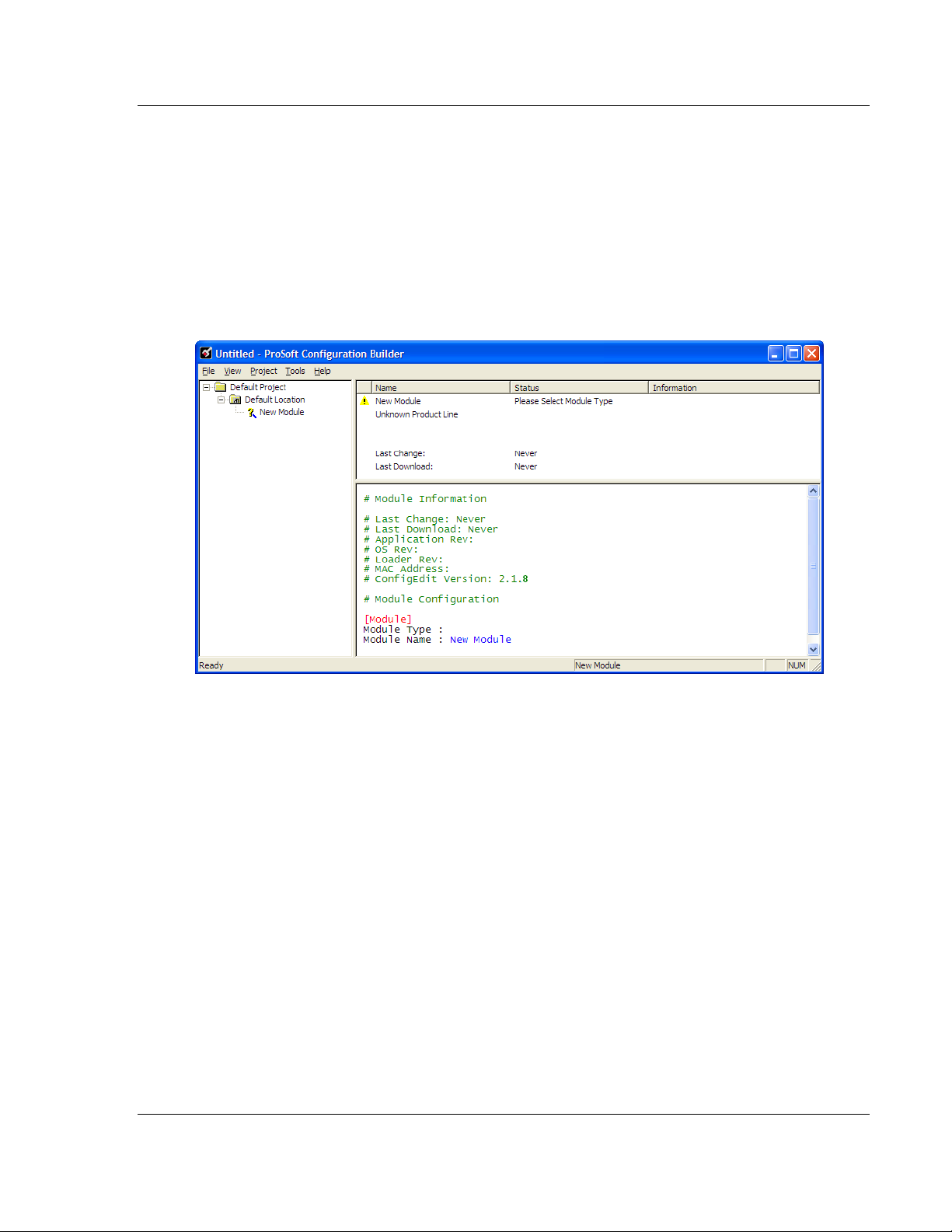
1.3.1 Set Up the Project
To begin, start ProSoft Configuration Builder. If you have used other Windows
configuration tools before, you will find the screen layout familiar. ProSoft
Configuration Builder’s window consists of a tree view on the left, an information
pane, and a configuration pane on the right side of the window. When you first
start ProSoft Configuration Builder, the tree view consists of folders for Default
Project and Default Location, with a Default Module in the Default Location
folder. The following illustration shows the ProSoft Configuration Builder window
with a new project.
Your first task is to add the ProLinx DNPS module to the project.
1 Use the mouse to select D
EFAULT MODULE in the tree view, and then click the
right mouse button to open a shortcut menu.
ProSoft Technology, Inc. Page 11 of 86
December 1, 2009
Page 12
ProLinx DNPS ♦ ProLinx Gateway Start Here
DNP 3.0 Slave User Manual
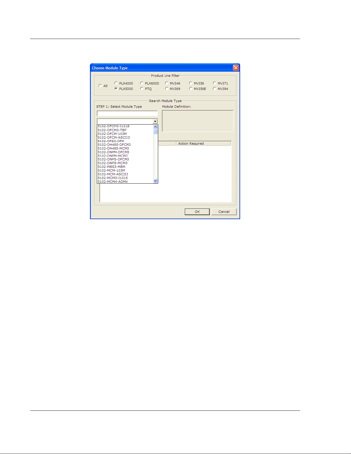
2 On the shortcut menu, choose C
C
HOOSE MODULE TYPE dialog box.
HOOSE MODULE TYPE. This action opens the
3 In the PRODUCT LINE FILTER area of the dialog box, select PROLINX GATEWAY.
In the SELECT MODULE TYPE dropdown list, select PROLINX DNPS, and then
click OK
to save your settings and return to the PROSOFT CONFIGURATION
BUILDER window.
The next task is to set the module parameters.
Page 12 of 86 ProSoft Technology, Inc.
December 1, 2009
Page 13
Start Here ProLinx DNPS ♦ ProLinx Gateway
User Manual DNP 3.0 Slave
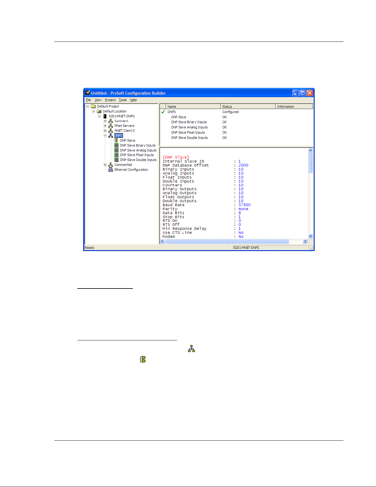
1.3.2 Set Module Parameters
Notice that the contents of the information pane and the configuration pane
changed when you added the ProLinx DNPS module to the project.
At this time, you may wish to rename the "Default Project" and "Default Location"
folders in the tree view.
To rename an object:
1 Select the object, and then click the right mouse button to open a shortcut
menu. From the shortcut menu, choose R
ENAME.
2 Type the name to assign to the object.
3 Click away from the object to save the new name.
To Configure Module Parameters
1 Click on the plus sign next to the
2 Double-click the
icon to open the EDIT dialog box.
icon to expand gateway information.
3 To edit a parameter, select the parameter in the left pane and make your
changes in the right pane.
4 Click OK
to save your changes.
ProSoft Technology, Inc. Page 13 of 86
December 1, 2009
Page 14
ProLinx DNPS ♦ ProLinx Gateway Start Here
DNP 3.0 Slave User Manual
Printing a Configuration File
1 Select the M
ODULE icon, and then click the right mouse button to open a
shortcut menu.
2 On the shortcut menu, choose V
V
IEW CONFIGURATION window.
3 On the V
P
RINT. This action opens the PRINT dialog box.
4 On the P
IEW CONFIGURATION window, open the FILE menu, and choose
RINT dialog box, choose the printer to use from the dropdown list,
select printing options, and then click OK.
1.4 DNPS Protocol Configuration
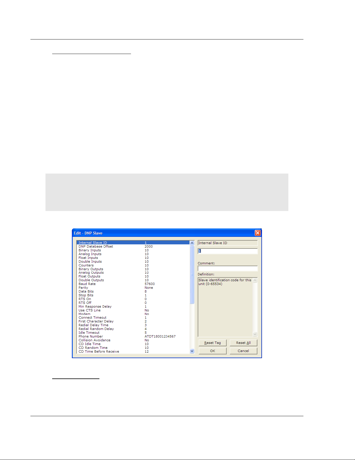
1.4.1 [DNP Slave]
This section provides information required to configure a slave application with
the module. Most entries contained within this section are self explanatory.
Note: A limitation of the DNP slave driver is that all points defined in the module slave database
must fit within one Class 0 poll. The maximum packet size for a Class 0 poll is 2048 bytes. A DNP
Message Size Calculator is available on the ProSoft Technology web site. This calculator will help
you ensure that the packet size fits within this requirement.
IEW CONFIGURATION. This action opens the
The following example shows a sample [DNP Slave] section:
Internal Slave ID
0 to 65534
This is the DNP address for the module. All messages with this address from the
master will be processed by the module.
Page 14 of 86 ProSoft Technology, Inc.
December 1, 2009
Page 15

Start Here ProLinx DNPS ♦ ProLinx Gateway
User Manual DNP 3.0 Slave
DNP Database Offset
0 to 3999
Offset in which to place DNP data.
Binary Inputs
0 to 500
Number of words for digital input points to configure in the DNP slave device.
Each word contains 16 binary input points.
Analog Inputs
0 to 500
Number of analog input points to configure in the DNP slave device. Each point
will occupy a one-word area in the module memory.
Float Inputs
0 to 250 points
Number of floating point input points to configure in the DNP slave device. Each
point will occupy a two-word area in the module's memory.
Double Inputs
0 to 125 points
Number of double floating point input points to configure in the DNP slave device.
Each point will occupy a four word area in the module's memory.
Counters
0 to 250
Number of counter points to configure in the DNP slave device. Each point will
occupy a two-word area in the module memory. This number corresponds to the
number of frozen counters. The application maps the counters to the frozen
counters directly.
Binary Outputs
0 to 500
Number of words for digital output points to configure in the DNP slave device.
Each word contains 16 binary output points.
Analog Outputs
0 to 500
Number of analog output points to configure in the DNP slave device. Each point
will occupy a one-word area in the module memory.
ProSoft Technology, Inc. Page 15 of 86
December 1, 2009
Page 16

ProLinx DNPS ♦ ProLinx Gateway Start Here
DNP 3.0 Slave User Manual
Float Outputs
0 to 250 points
Number of floating point output points to configure in the DNP slave device. Each
point will occupy a two-word area in the module's memory.
Double Outputs
0 to 125 points
Number of double floating point output points to configure in the DNP slave
device. Each point will occupy a four-word area in the module's memory.
Baud Rate
This is the baud rate to be used on the port. Enter the baud rate as a value. For
example, to select 19K baud, enter 19200.
Baud Rate Parameter Value
110 110
150 150
300 300
600 600
1200 12 or 1200
2400 24 or 2400
4800 48 or 4800
9600 96 or 9600
19,200 19, 192 or 19200
28,800 28, 288 or 28800
57,600 57 or 576
115,200 115 or 1152
Parity
None, Odd, Even
Parity is a simple error checking algorithm used in serial communication. This
parameter specifies the type of parity checking to use.
All devices communicating through this port must use the same parity setting.
Data Bits
or 8
7
This parameter sets the number of data bits for each word used by the protocol.
All devices communicating through this port must use the same number of data
bits.
Page 16 of 86 ProSoft Technology, Inc.
December 1, 2009
Page 17

Start Here ProLinx DNPS ♦ ProLinx Gateway
User Manual DNP 3.0 Slave
Stop Bits
1 or 2
Stop bits signal the end of a character in the data stream. For most applications,
use one stop bit. For slower devices that require more time to re-synchronize,
use two stop bits.
All devices communicating through this port must use the same number of stop
bits.
RTS On
0 to 65535 milliseconds
This parameter sets the number of milliseconds to delay after Ready To Send
(RTS) is asserted before data will be transmitted.
RTS Off
0 to 65535 milliseconds
This parameter sets the number of milliseconds to delay after the last byte of
data is sent before the RTS modem signal will be set low.
Min Response Delay
0 to 65535 milliseconds
Minimum time between receiving a request and transmitting a response. Allows
master time to disable transmitter on an RS-485 network.
Use CTS Line
ES or NO
Y
This parameter specifies if the Clear To Send (CTS) modem control line is to be
used or not. If the parameter is set to N
the parameter is set to Y
ES, the CTS line will be monitored and must be high
O, the CTS line will not be monitored. If
before the gateway will send data. Normally, this parameter is required when
half-duplex modems are used for communication (2-wire). This procedure is
commonly referred to as hardware handshaking.
Modem
Yes or No
This parameter defines if a dial-up modem is used on the DNP slave port. If the
value is set to No, no modem is used. If the parameter is set to Yes, a modem is
used.
ProSoft Technology, Inc. Page 17 of 86
December 1, 2009
Page 18

ProLinx DNPS ♦ ProLinx Gateway Start Here
DNP 3.0 Slave User Manual
Connect Timeout
0 to 65535
Defines the number of milliseconds to wait for the CD signal to be set high. The
CD signal indicates a connection is made using a dial-up modem.
First Character Delay
0 to 65535
Defines the number of milliseconds to wait before sending the first message after
the connection is first made. This delay only applies to the first packet sent to the
modem.
Redial Delay Time
0 to 32000
Defines the minimum number of milliseconds to wait before a redial attempt is
made by the slave.
Redial Random Delay
0 to 32000
Defines a random millisecond time range to be added to the redial delay time
before the modem is accessed.
Idle Timeout
0 to 65535
Defines the number of milliseconds the modem is inactive before it will
disconnect.
Phone Number
ASCII String Data
This field contains a null-terminated, ASCII character string used by the dial-up
modem. The string must contain all characters required by the modem. An
example string is ATDT1800222333. Maximum length is 34 bytes including the
terminating 0.
Collision Avoidance
Yes or No
This parameter defines if the collision avoidance functionality is to be applied to
the port. If the parameter is set to No, collision avoidance is not used. It will be
used if set to Yes. If collision avoidance is used, it requires a special cable.
Page 18 of 86 ProSoft Technology, Inc.
December 1, 2009
Page 19

Start Here ProLinx DNPS ♦ ProLinx Gateway
User Manual DNP 3.0 Slave
CD Idle Time
0 to 32000
Defines the minimum number of milliseconds to wait before transmitting a
message after the CD signal is recognized as low.
CD Random Time
0 to 32000
Defines the range of random time to be added to the CD Idle Time before a
message will be transmitted from the slave.
CD Time Before Receive
0 to 65535
Defines the number of milliseconds to wait before receiving characters after the
CD signal is recognized as high.
BI Class
0 to 3
This parameter specifies the default class to be utilized for all the binary input
points in the DNP database that are not defined in the override list section.
AI Class
0 to 3
This parameter specifies the default class to be utilized for all the analog input
points in the DNP database that are not defined in the override list section.
Float Class
0 to 3
This parameter specifies the default class to be utilized for all the floating-point
input points in the DNP database that are not defined in the override list section.
Double Class
0 to 3
Default class for double input events.
AO DB Trigger
Yes or No
Causes the last values to not match the database values when the DNP master
sends an AO command to the module. This can be used to cause the module to
issue a conditional write command on the other protocol interface, even if the
value received is the same as received previously.
ProSoft Technology, Inc. Page 19 of 86
December 1, 2009
Page 20

ProLinx DNPS ♦ ProLinx Gateway Start Here
DNP 3.0 Slave User Manual
BO DB Trigger
Yes or No
Causes the last values to not match the database values when the DNP master
sends a BO command to the module. This can be used to cause the module to
issue a conditional write command on the other protocol interface, even if the
value received is the same as received previously.
AI Deadband
0 to 32767
This parameter specifies the default deadband value assigned to all points not
defined in the override list for the analog input point type in the DNP database.
Float Deadband
0 to maximum float value
This parameter specifies the default deadband value assigned to all points not
defined in the override list for the floating-point input point type in the DNP
database.
Double Deadband
0 to 100000
This parameter specifies the default deadband value assigned to all points not
defined in the override list for the double float input point type in the DNP
database.
Select/Operate Arm Time
1 to 65535 milliseconds
Time period after select command received in which operate command will be
performed. Once the select command is received, the operate command will only
be honored if it arrives within this period of time.
Write Time Interval
0 to 1440 minutes
Time interval to set the need time IIN bit (0=never), which will cause the master
to write the time. Stored in milliseconds in the module memory.
Data Link Confirm Mode
Coded Value (N=Never, S=Sometimes, A=Always)
IED can request acknowledgement from master station when sending data. The
codes are as follows: 0=Never, 1=Sometimes, 2=Always
Page 20 of 86 ProSoft Technology, Inc.
December 1, 2009
Page 21

Start Here ProLinx DNPS ♦ ProLinx Gateway
User Manual DNP 3.0 Slave
Data Link Confirm Tout
1 to 65535 milliseconds
Time period to wait for Master Data Link confirmation of last frame sent. This
time is in milliseconds. This parameter is only used if the frame is sent with
confirmation requested.
Data Link Max Retry
0 to 255 retries
Maximum number of retries at the Data Link level to obtain a confirmation. If this
value is set to 0, retries are disabled at the data link level of the protocol. This
parameter is only used if the frame is sent with confirmation requested.
App Layer Confirm Tout
1 to 65535 milliseconds
Event data contained in the last response may be sent again if not confirmed
within the millisecond time period set. If application layer confirms are used with
data link confirms, ensure that the application layer confirm timeout is set long
enough.
Unsolicited Response
Y or N
Set if the slave unit will send unsolicited response messages. If set to N, the
slave will not send unsolicited responses. If set to Y, the slave will send
unsolicited responses.
Class 1 Unsol Resp Min
1 to 255 events
Minimum number of events in Class 1 required before an unsolicited response
will be generated.
Class 2 Unsol Resp Min
1 to 255 events
Minimum number of events in Class 2 required before an unsolicited response
will be generated.
Class 3 Unsol Resp Min
1 to 255 events
Minimum number of events in Class 3 required before an unsolicited response
will be generated.
ProSoft Technology, Inc. Page 21 of 86
December 1, 2009
Page 22
ProLinx DNPS ♦ ProLinx Gateway Start Here
DNP 3.0 Slave User Manual
Unsol Resp Delay
0 to 65535 milliseconds
Maximum number of 1 millisecond intervals to wait after an event occurs before
sending an unsolicited response message. If set to 0, only use minimum number
of events.
Uresp Master Address
0 to 65534
DNP destination address where unsolicited response messages are sent.
AI Events with time
Y or N
This parameter determines if the analog input events generated by the module
will include the date and time of the event. If the parameter is set to N, the default
is set to no time data. If the parameter is set to Y, the default object will include
the time of the event.
Time Sync Before Events
Y or N
This parameter determines if events are to be generated by the module before
the time synchronization from the master unit. If the parameter is set to N, no
events will be generated until the module’s time has been synchronized. If the
parameter is set to Y, events will always be generated.
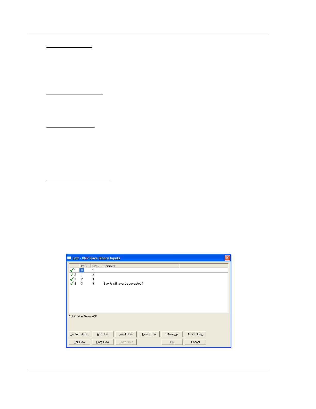
1.4.2 [DNP Slave Binary Inputs]
This area is to override the class (2) binary input database points.
Page 22 of 86 ProSoft Technology, Inc.
December 1, 2009
Page 23
Start Here ProLinx DNPS ♦ ProLinx Gateway
User Manual DNP 3.0 Slave
Point #
This is the information object address of the point.
Class
Class 1 - Highest priority
Class 2 - Middle priority
Class 3 - Lowest priority
0 - Disable.
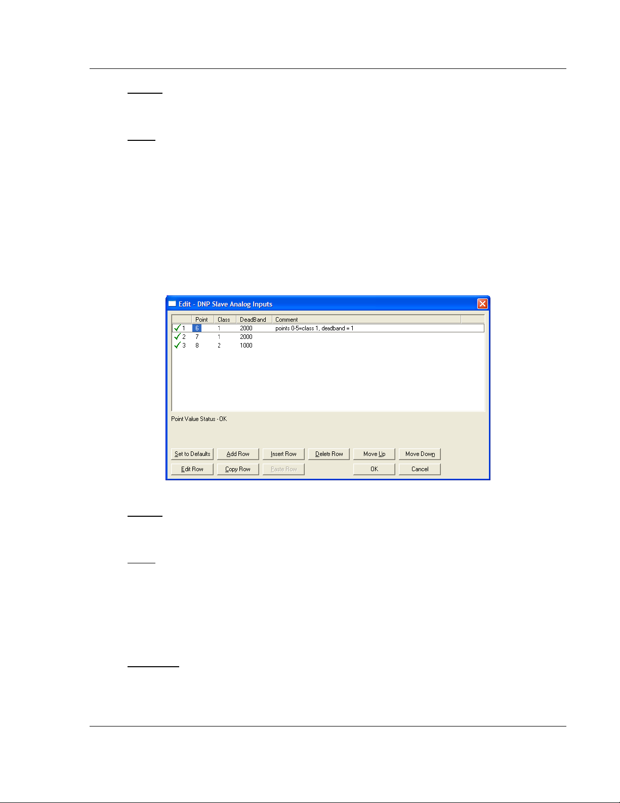
1.4.3 [DNP Slave Analog Inputs]
This area is to override the class (3) and deadband for the integer analog input
database. The point # is the offset from the start of the analog input database.
Point #
This is the information object address of the point.
Class
Class 1 - Highest priority
Class 2 - Middle priority
Class 3 - Lowest priority
0 - Disable.
Deadband
A range of values within which the module will avoid generating events.
ProSoft Technology, Inc. Page 23 of 86
December 1, 2009
Page 24
ProLinx DNPS ♦ ProLinx Gateway Start Here
DNP 3.0 Slave User Manual
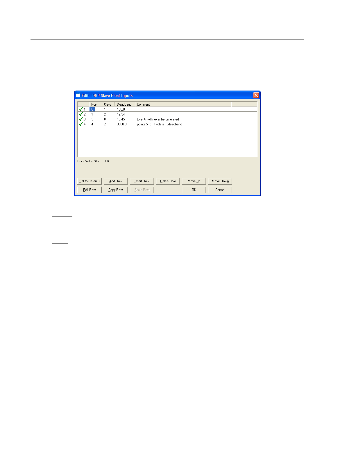
1.4.4 [DNP Slave Float Inputs]
This area is to override the class (3) and debased for the single float database.
The point # is not the address in the analog database, but is the offset from the
start of the single floating-point database.
Point #
This is the information object address of the point.
Class
Class 1 - Highest priority
Class 2 - Middle priority
Class 3 - Lowest priority
0 - Disable.
Deadband
A range of values within which the module will avoid generating events.
Page 24 of 86 ProSoft Technology, Inc.
December 1, 2009
Page 25
Start Here ProLinx DNPS ♦ ProLinx Gateway
User Manual DNP 3.0 Slave
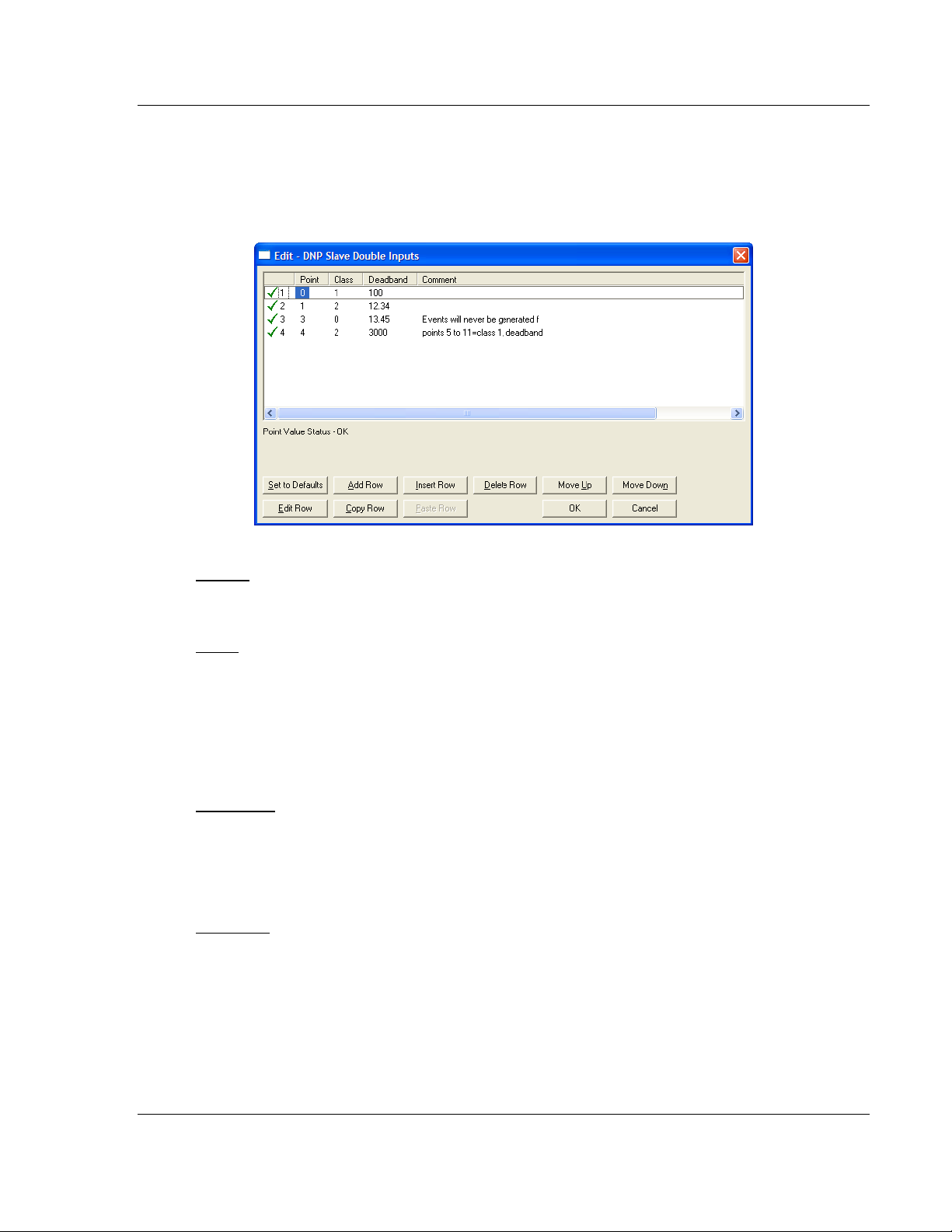
1.4.5 [DNP Slave Double Inputs]
This area is to override the class (3) and deadband for the double float database.
The point # is not the address in the analog database, but is the offset from the
start of the double floating-point database.
Point #
This is the information object address of the point.
Class
Class 1 - Highest priority
Class 2 - Middle priority
Class 3 - Lowest priority
0 - Disable.
Deadband
A range of values within which the module will avoid generating events.
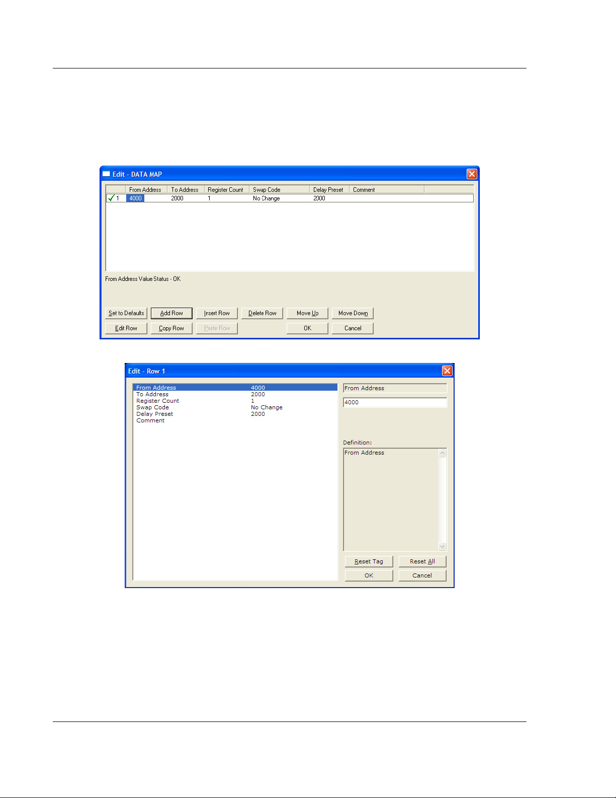
1.4.6 Common Configuration
Data Map
[DATA MAP] section allows you to copy data between areas in the gateway’s
The
internal database.
You can copy to 100 registers at a time, and you can configure up to 200
separate copy commands.
For example, you can copy data from the error or status tables in upper memory
to internal database registers in the User Data memory area.
ProSoft Technology, Inc. Page 25 of 86
December 1, 2009
Page 26
ProLinx DNPS ♦ ProLinx Gateway Start Here
DNP 3.0 Slave User Manual
You can also rearrange the byte and/or word order during the copy process, for
example, to convert floating-point values to the correct format for a different
protocol.
You can also use the Data Map to condense widely dispersed data into one
contiguous data block, making it easier to access.
From Address
0 to highest Status Data address
This field specifies the internal database register to copy from. This address can
range from the Data area as well as the Status Data Area of the product
Page 26 of 86 ProSoft Technology, Inc.
December 1, 2009
Page 27

Start Here ProLinx DNPS ♦ ProLinx Gateway
User Manual DNP 3.0 Slave
To Address
0 to highest User Data Register Address
The destination for the copy is always within the User Data registers area. Take
care to specify a destination address that will not overwrite data that may be
required for other purposes.
Register Count
1 to 100
This parameter specifies the number of registers to copy.
Swap Code
No Change, Word Swap, Word and Byte Swap, Byte Swap
You may need to swap the order of the bytes in the registers during the copy
process in order to change the alignment of bytes between dissimilar protocols.
This parameter is helpful when dealing with floating-point or other multi-register
values, as there is no standard method of storage of these data types in slave
devices.
The following table defines the values and their associated operations:
Swap Code Description
No Swap No Change is made in the byte ordering (1234 = 1234)
Word Swap The words are swapped (1234=3412)
Word and
Byte Swap
Bytes The bytes in each word are swapped (1234=2143)
The words are swapped then the bytes in each word are swapped (1234=4321)
ProSoft Technology, Inc. Page 27 of 86
December 1, 2009
Page 28

ProLinx DNPS ♦ ProLinx Gateway Start Here
DNP 3.0 Slave User Manual
Delay Preset
This parameter sets an interval for each [Data Map] copy operation. The value
you put for the Delay Preset is not a fixed amount of time. It is the number of
firmware scans that must transpire between copy operations.
The firmware scan cycle can take a variable amount of time, depending on the
level of activity of the protocol drivers running on the ProLinx gateway and the
level of activity on the gateway’s communications ports. Each firmware scan can
take from 1 to several milliseconds to complete. Therefore, [Data Map] copy
operations cannot be expected to happen at regular intervals.
If multiple copy operations (several rows in the [Data map] section) happen too
frequently or all happen in the same update interval, they could delay the process
scan of the gateway protocols, which could result in slow data updates or missed
data on communications ports. To avoid these potential problems, you should set
the Delay Preset to different values for each row in the [Data Map] section and
set them to higher, rather than lower, numbers.
For example, Delay Preset values below 1000 could begin to cause a noticeable
delay in data updates through the communications ports. And you should not set
all Delay Presets to the same value. Instead, use different values for each row in
the [Data Map] such as 1000, 1001, and 1002 or any other different Delay Preset
values you like. This will prevent the copies from happening concurrently and
prevent possible process scan delays.
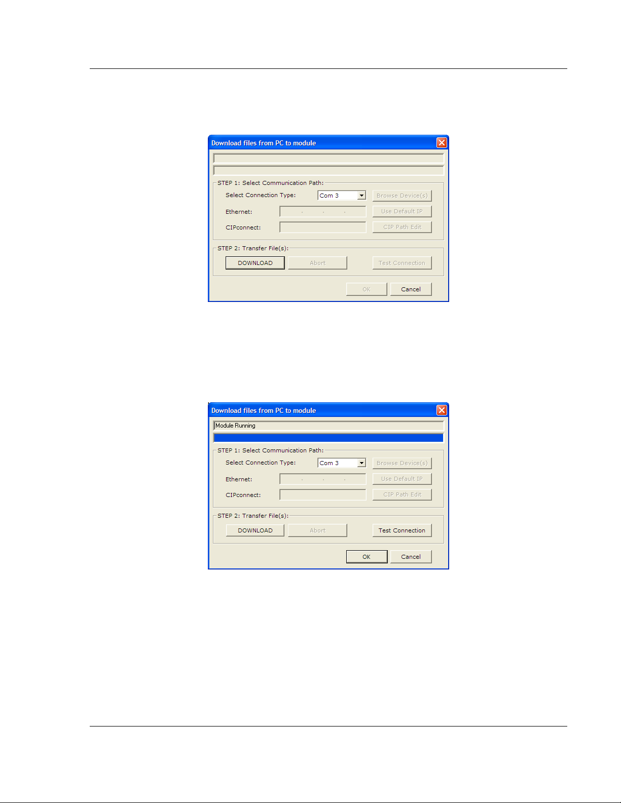
1.5 Download the Project to the Module
In order for the module to use the settings you configured, you must download
(copy) the updated Project file from your PC to the module.
To Download the Project File
1 In the tree view in ProSoft Configuration Builder, click once to select the
ProLinx DNPS module.
Page 28 of 86 ProSoft Technology, Inc.
December 1, 2009
Page 29
Start Here ProLinx DNPS ♦ ProLinx Gateway
User Manual DNP 3.0 Slave
2 Open the P
ROJECT menu, and then choose MODULE / DOWNLOAD. The
program will scan your PC for a valid com port (this may take a few seconds).
When PCB has found a valid com port, the D
OWNLOAD dialog box will open.
3 Choose the com port to use from the dropdown list, and then click the
D
OWNLOAD button.
The module will perform a platform check to read and load its new settings.
When the platform check is complete, the status bar in the D
OWNLOAD dialog
box with the message "Module Running".
ProSoft Technology, Inc. Page 29 of 86
December 1, 2009
Page 30

ProLinx DNPS ♦ ProLinx Gateway Start Here
DNP 3.0 Slave User Manual
Page 30 of 86 ProSoft Technology, Inc.
December 1, 2009
Page 31

Diagnostics and Troubleshooting ProLinx DNPS ♦ ProLinx Gateway User Manual DNP 3.0 Slave
2 Diagnostics and Troubleshooting
In This Chapter
Requirements........................................................................................31
LED Indicators.......................................................................................35
Serial Port DNPS Error and Status Data...............................................36
There are two ways to troubleshoot ProLinx gateways: LEDs located on the front
of the gateway, and a Debug port that provides a view into the gateway’s internal
database.
2.1 Requirements
In order to use the Debug capabilities of any ProLinx Module, you will need the
following:
A PC running ProSoft Configuration Builder or HyperTerminal software
A Null Modem cable
A Mini-DIN to DB-9M connector
Configuration and executable files described earlier
2.1.1 The Configuration/Debug Menu
The Configuration and Debug menu for this module is arranged as a tree
structure, with the Main Menu at the top of the tree, and one or more sub-menus
for each menu command. The first menu you see when you connect to the
module is the Main menu.
Because this is a text-based menu system, you enter commands by typing the
command letter from your computer keyboard in the diagnostic window in
ProSoft Configuration Builder (PCB). The module does not respond to mouse
movements or clicks. The command executes as soon as you press the
command letter — you do not need to press [E
letter, a new screen will be displayed in your terminal application.
Required Hardware
You can connect directly from your computer’s serial port to the serial port on the
module to view configuration information, perform maintenance, and send
(upload) or receive (download) configuration files.
NTER]. When you type a command
ProSoft Technology recommends the following minimum hardware to connect
your computer to the module:
80486 based processor (Pentium preferred)
ProSoft Technology, Inc. Page 31 of 86
December 1, 2009
Page 32

ProLinx DNPS ♦ ProLinx Gateway Diagnostics and Troubleshooting
DNP 3.0 Slave User Manual
1 megabyte of memory
At least one UART hardware-based serial communications port available.
USB-based virtual UART systems (USB to serial port adapters) often do not
function reliably, especially during binary file transfers, such as when
uploading/downloading configuration files or module firmware upgrades.
Using the Diagnostic Window in ProSoft Configuration Builder
To connect to the module’s Configuration/Debug serial port,
1 Start PCB, and then select the module to test. Click the right mouse button to
open a shortcut menu.
2 On the shortcut menu, choose D
IAGNOSTICS.
Page 32 of 86 ProSoft Technology, Inc.
December 1, 2009
Page 33

Diagnostics and Troubleshooting ProLinx DNPS ♦ ProLinx Gateway
User Manual DNP 3.0 Slave
This action opens the DIAGNOSTICS dialog box.
3 Press [?]
to open the Main Menu.
Important: The illustrations of configuration/debug menus in this section are intended as a general
guide, and may not exactly match the configuration/debug menus in your own module.
If there is no response from the module, follow these steps:
1 Click to configure the connection. On the Connection Setup dialog box, select
a valid com port or other connection type supported by the gateway.
2 Verify that the null modem cable is connected properly between your
computer’s serial port and the module. A regular serial cable will not work.
3 On computers with more than one serial port, verify that your communication
program is connected to the same port that is connected to the module.
ProSoft Technology, Inc. Page 33 of 86
December 1, 2009
Page 34

ProLinx DNPS ♦ ProLinx Gateway Diagnostics and Troubleshooting
DNP 3.0 Slave User Manual
If you are still not able to establish a connection, contact ProSoft Technology for
assistance.
Navigation
All of the sub-menus for this module contain commands to redisplay the menu or
return to the previous menu. You can always return from a sub-menu to the next
higher menu by pressing [M]
on your keyboard.
The organization of the menu structure is represented in simplified form in the
following illustration:
The remainder of this section shows you the menus available for this module,
and briefly discusses the commands available to you.
Keystrokes
The keyboard commands on these menus are almost always non-case sensitive.
You can enter most commands in lower case or capital letters.
The menus use a few special characters ([?],
exactly as shown. Some of these characters will require you to use the [S
[-], [+], [@]) that must be entered
HIFT],
[CTRL] or [ALT] keys to enter them correctly. For example, on US English
keyboards, enter the [?]
command as [SHIFT][/].
Also, take care to distinguish capital letter [I]
number [1];
likewise for capital letter [O] and number [0]. Although these
from lower case letter [L] (L) and
characters look nearly the same on the screen, they perform different actions on
the module.
Page 34 of 86 ProSoft Technology, Inc.
December 1, 2009
Page 35

Diagnostics and Troubleshooting ProLinx DNPS ♦ ProLinx Gateway
User Manual DNP 3.0 Slave
2.2 LED Indicators
Troubleshooting the operation of the DNP Slave port can be performed using
several methods.
The first and quickest is to scan the LEDs on the module to determine the
existence and possibly the cause of a problem. This section provides insight into
the operation of the Serial Port status LEDs. Information on the module’s other
LEDs can be found in the ProLinx Reference Guide.
2.2.1 Base Module LEDs
LED State Description
Power
Err
Off
Green Solid Power is connected to the power terminals.
Off Normal operation. Fault
Red Solid
Off Normal operation. Cfg
Amber Solid
Off Normal operation.
Flashing
Solid Red
Power is not connected to the power terminals or source is insufficient
to properly power the gateway (800mA at 24vdc minimum required)
A critical error has occurred. Program executable has failed or has
been user-terminated and is no longer running. Press Reset p/b or
cycle power to clear error. If not, use the Debug procedures described
later in this manual.
The unit is in configuration mode. The configuration file is currently
being downloaded or, after power-up, is being read, the unit is
implementing the configuration values, and initializing the hard ware.
This will occur during power cycle, or after pressing the reset button. It
also occurs after a cold/warm boot command is received.
An error condition has been detected and is occurring on one of the
application ports. Check configuration and troubleshoot for
communication errors.
This error flag is cleared at the start of each command attempt
(master/client) or on each receipt of data (slave/adapter/server); so, if
this condition exists, it indicates a large number of errors are occurring
in the application (due to bad configuration) or on one or more ports
(network communication failures).
2.2.2 LEDs for Port 0 Serial Port
Some ProLinx modules have three extra serial ports. Each of these serial ports
has two LEDs indicating status.
LED Color Description
Off No activity on the port. Port 0 - ACT
Green Flash The port is either actively transmitting or receiving data
Port 0 - ERR
Off
Red On or Flashing
ProSoft Technology, Inc. Page 35 of 86
December 1, 2009
Normal state. When off and Port Active led is indicating
activity, there are no communication errors
Activity on this led indicates some communication error
was detected, either during transmit or receive
Page 36

ProLinx DNPS ♦ ProLinx Gateway Diagnostics and Troubleshooting
DNP 3.0 Slave User Manual
2.2.3 4101 Series LEDs
LED State Description
Off Power is not connected to the power terminals. Power
Power is connected to the power terminals. Verify that the other LEDs
for operational and functional status light.
The Debug/Configuration mode is active (applies to gateways that
support pass-through on Debug port - such as DFCM units).
If CFG LED is not on, a critical error has occurred. Program executable
has failed or has been user-terminated and is no longer running. Press
Reset p/b or cycle power to clear error. If not, use the Debug
procedures described later in this manual.
If Fault LED is on, the Debug/Configuration Mode is active (if the
gateway supports pass-through on the Debug port - such as DFCM
units).
If the Fault LED is off, the unit is in the configuration mode. The
configuration file is being read and the unit is implementing the
configuration values and initializing the hardware. This will occur during
power cycle, or after pressing reset button. It also occurs after a
cold/warm boot command is received.
An error condition has been detected and is occurring. Check
configuration.
This condition is indicative of a large number of errors in the application
interface communications. The gateway's error flag is cleared at the
start of each command (master/client) or receipt of data
(slave/adapter/server).
ERR
Green Solid
Off Normal operation. Fault
Red Solid
Off Normal operation. CFG
Amber Solid
Off Normal operation.
Flashing
Solid Red
2.3 Serial Port DNPS Error and Status Data
The second and most thorough troubleshooting method for debugging the
operation of the DNPS driver (and the module in general) is the powerful Debug
port on the module which provides much more complete access to the internal
operation and status of the module. Accessing the Debug capabilities of the
module is accomplished easily by connecting a PC to the Debug port and loading
a terminal program such as ProSoft Configuration Builder or HyperTerminal.
Note: 4101 series modules that use both serial ports (Debug and Port x) as application ports (for
example, 4101-MCM-DFCM) must be reset or power-cycled in order to enable the selected port as
a Debug port. To enable the debug port, connect to the port using a null-modem serial cable, and
then press and hold the [A] key on the keyboard while resetting or power cycling the card. Do not
release the key until HyperTerminal shows the debug port menu. Debug mode can be enabled on
either port. The upload/download command is only available when connected to the Debug port.
Page 36 of 86 ProSoft Technology, Inc.
December 1, 2009
Page 37

Diagnostics and Troubleshooting ProLinx DNPS ♦ ProLinx Gateway
User Manual DNP 3.0 Slave
2.3.1 Viewing Error and Status Data
The following topics list the register addresses that will contain error and status
data. You use the Database View option to view the contents of these registers.
Refer to the ProLinx Reference Guide for detailed information on viewing error
and status registers.
2.3.2 General Module Status Data
The following table describes the general module status data address registers.
Internal
Database
Address
1000 Program Cycle Counter
1001 to 1002 Product Name (ASCII)
1003 to 1004 Revision (ASCII)
1005 to 1006
1007 to 1008
1009 to 1019 No Valid Data
Variable Name Description
These two words contain the product name of the
module in ASCII format.
These two words contain the product revision level
of the firmware in ASCII format.
Operating System
Revision (ASCII)
Production Run Number
(ASCII)
These two words contain the module’s internal
operating system revision level in ASCII format.
These two words contain the production "batch"
number for the particular chip in the module in
ASCII format.
2.3.3 DNPS Port - Error and Status
The serial port (DNP 3.0 Slave) Error and Status Data areas are discussed in this
section.
The data area is initialized with zeros whenever the module is initialized. This
occurs during a cold-start (power-on), reset (reset push-button pressed) or a
warm-boot operation (commanded or loading of new configuration).
Internal
Database
Address
1010
1011
1012
Variable Name Description
DNP Slave Port total number of
message frames received by slave
DNP Slave Port total number of
response message frames sent
from slave
DNP Slave Port total number of
message frames seen by slave
This value represents the total number of
message frames that have matched this
slave’s address on this port. This count
includes message frames that the slave
may or may not be able to parse and
respond.
This value represents the number of
good (non-error) responses that the
slave has sent to the master on this port.
The presumption is that if the slave is
responding, the message was good.
Note: This is a frame count.
This value represents the total number of
message frames received by the slave,
regardless of the slave address.
ProSoft Technology, Inc. Page 37 of 86
December 1, 2009
Page 38

ProLinx DNPS ♦ ProLinx Gateway Diagnostics and Troubleshooting
DNP 3.0 Slave User Manual
Internal
Database
Address
1013 DNP Slave Binary Input Event count
1014
1015 DNP Slave Float Input Event Count
1016
1017
1018
1019
1020
1021
1022 Unsolicited Message Errors
1023 Cycle Count
1024
1025
1026
1027
Variable Name Description
This value contains the total number of
binary input events that have occurred.
DNP Slave Analog Input Event
count
DNP Slave Double Input Event
Count
DNP Slave bad function code error
(Application Layer Error)
DNP Slave object unknown error
(Application Layer Error)
DNP Slave out of range error
(Application Layer Error)
DNP Slave message overflow error
(Application Layer Error)
DNP Slave multi-frame message
from DNP Master error (Application
Layer Error)
DNP Slave synchronization error
count (Physical Layer Error)
DNP Slave overrun error count
(Physical Layer Error)
DNP Slave length error count
(Physical Layer Error)
DNP Slave bad CRC error (Data
Link Layer Error)
This value contains the total number of
analog input events that have occurred.
This value contains the total number of
float events that have occurred.
This value contains the total number of
double events that have occurred.
This value counts the number of times a
bad function code for a selected
object/variation is received by the slave
device.
This value counts the number of times a
request for an unsupported object is
received by the slave device.
This value counts the number of times a
parameter in the qualifier, range or data
field is not valid or out of range.
This value counts the number of times an
application response message from the
slave is too long to transmit.
This value counts the number of times
the slave receives a multi-frame
message from the master. The
application does not support multi-frame
master messages.
This value counts the number of
unsuccessful unsolicited messages
transmitted by the slave unit.
This value is incremented each program
scan.
This value counts the number of times a
sync error occurs. The error occurs when
extra bytes are received before the start
bytes (0x05 and 0x64) are received.
This value counts the number of times
the overrun error occurs. This error
occurs when the mainline Data Link
Layer routine cannot read the data
received on the communication port
before it is overwritten.
This value counts the number of times an
invalid length byte is received. If the
length of the message does not match
the length value in the message, this
error occurs.
This value counts the number of times a
bad CRC value is received in a
message.
Page 38 of 86 ProSoft Technology, Inc.
December 1, 2009
Page 39

Diagnostics and Troubleshooting ProLinx DNPS ♦ ProLinx Gateway
User Manual DNP 3.0 Slave
Internal
Database
Address
1028
1029
1030
Variable Name Description
DNP Slave user data overflow error
(Transport Layer Error)
DNP Slave sequence error
(Transport Layer Error)
DNP Slave address error (Transport
Layer Error)
This value counts the number of times
the application layer receives a message
fragment buffer which is too small.
This value counts the number of times
the sequence numbers of multi-frame
request fragments do not increment
correctly.
This value counts the number of times
the source addresses contained in a
multi-frame request fragments do not
match.
ProSoft Technology, Inc. Page 39 of 86
December 1, 2009
Page 40

ProLinx DNPS ♦ ProLinx Gateway Diagnostics and Troubleshooting
DNP 3.0 Slave User Manual
Page 40 of 86 ProSoft Technology, Inc.
December 1, 2009
Page 41

Reference ProLinx DNPS ♦ ProLinx Gateway
User Manual DNP 3.0 Slave
3 Reference
In This Chapter
Product Specifications...........................................................................41
Communication Port Cables..................................................................44
Functional Overview..............................................................................50
DNP Collision Avoidance.......................................................................64
IIN Response: Slave Port......................................................................65
IIN Bit Definitions...................................................................................66
Event Size Computation........................................................................67
Device Profile........................................................................................68
Subset Definition...................................................................................70
3.1 Product Specifications
3.1.1 DNP 3.0 Slave Port Specifications
Type Specifications
General Parameters
Internal Database Binary Inputs: 0 to 100 word count
Communication parameters Port 0: Baud Rate: 110 to 38.4K baud
DNP Mode DNP 3.0 Slave - Level 2
DNP Object Support
Analog Inputs: 0 to 100 points of analog inpu t data
Float Inputs: 250 points
Double Inputs: 125 points
Counters: 0 to 50 points of counter data
Binary Outputs: 0 to 100 word count
Analog Outputs: 0 to 100 points of analog output
Float Outputs: 250 points
Double Outputs: 125 points
Binary Input Events: 0 to 100 binary input event buffer
Analog Input Events: 0 to 100 analog input event buffer
Stop Bits: 1
Data Size: 8 bits
Parity: None
RTS Timing delays: 0 to 65535 milliseconds
See Reference chapter for full Object Definition document
ProSoft Technology, Inc. Page 41 of 86
December 1, 2009
Page 42

ProLinx DNPS ♦ ProLinx Gateway Reference
DNP 3.0 Slave User Manual
Type Specifications
DNP Slave
Node address 0 to 65534 (software selectable)
Status Data
Error codes, counters and port status available per configured
slave port
3.1.2 Serial Port Specifications
Type Specifications
Serial Ports
Serial Port Adapter Cables
Config Port Connector/ Pinout DB-9F connector / DTE pinout
Serial Port Isolation 2500V RMS port-to-port isolation per UL 1577.
Serial Port Protection
One Mini DIN to DB-9M adapter cable included for
each configurable serial port
3000V DC min. port to ground and port to logic
power isolation.
RS-485/422 port interface lines TVS diode protected
at +/- 27V standoff voltage.
RS-232 port interface lines fault protected to +/- 36V
power on, +/- 40V power off.
Note: On all ProLinx gateways, data from the application port on the main board, serial Port 0, is
not buffered. Packets go directly to and from the serial chipset to the processor. This has the
potential to cause the serial communications to become erratic at baud rates above 38,400 baud.
ProLinx gateways with 4 serial ports have a separate serial interface board for serial Ports 1, 2,
and 3. These serial ports are buffered and can handle communications up to 115,200 baud.
Page 42 of 86 ProSoft Technology, Inc.
December 1, 2009
Page 43

Reference ProLinx DNPS ♦ ProLinx Gateway
User Manual DNP 3.0 Slave
3.1.3 Functional Specifications - DNP 3.0 Slave
The DNP 3.0 Slave driver provides extensive support for Slave implementations
of the protocol. The serial port on the gateway is user-configurable to support the
DNP 3.0 protocol (Slave, Error Checking, Baud rate, and so on).
General Parameters
Internal Database Binary Inputs: 0 to 500 word count
Analog Inputs: 0 to 500 points
Counters: 0 to 250 points
Binary Outputs: 0 to 200 word count
Analog Outputs: 0 to 500 points
Binary Input Events: 0 to 100 event buffer
Analog Input Events: 0 to 100 event buffer
Communication parameters Baud Rate: 110 to 115K baud
Stop Bits: 1
Data Size: 8 bits
Parity: None
RTS Timing delays: 0 to 65535 milliseconds
DNP Mode DNP 3.0 Slave - Level 2
DNP Slave
Node address 0 to 65534 (software selectable)
3.1.4 Hardware Specifications
Specification Description
Power Supply
Current Load 500 mA max@ 32 VDC max
Operating Temperature -20 to 50°C (-4 to 122°F)
Storage Temperature -40 to 85°C (-40 to 185°F)
Relative Humidity 5% to 95% (non-condensing)
Dimensions
LED Indicators
Configuration
Serial Port
24 VDC nominal
18 to 32 VDC allowed
Positive, Negative, GND Terminals
2.5 mm screwdriver blade
Standard: 5.20 H x 2.07 W x 4.52 D inches
(13.2 cm H x 5.25 cm W x 11.48cm D)
Extended: 5.20 H x 2.73 W x 4.52 D inches
(13.2 cm H x 6.934 cm W x 11.48cm D)
Power and Module Status
Application Status
Serial Port Activity LED
Serial Activity and Error LED Status
DB-9M RS-232 only
No hardware handshaking
ProSoft Technology, Inc. Page 43 of 86
December 1, 2009
Page 44

ProLinx DNPS ♦ ProLinx Gateway Reference
DNP 3.0 Slave User Manual
Specification Description
Ethernet Port
(Ethernet protocol gateways
only)
Application Serial Port(s)
(Serial protocol gateways
only)
Serial Port Isolation
Shipped with Each Unit
10Base-T half duplex RJ45 Connector
Link and Activity LED indicators
Electrical Isolation 1500 V rms at 50 Hz to 60 Hz for 60 s, applied as
specified in section 5.3.2 of IEC 60950: 1991
Ethernet Broadcast Storm Resiliency = less than or equal to 5000
[ARP] frames-per-second and less than or equal to 5 minutes
duration
RS-232/422/485
RS-232 handshaking configurable
RS-422/485 DB-9 to Screw Terminal Adaptor
Note: The number of serial application ports depends on the module
type, and the combination of protocols.
2500V RMS port signal isolation per UL 1577
3000V DC min. isolation port to ground and port to logic
Mini-DIN to DB-9M serial cables
4 ft RS-232 configuration cable
2.5mm screwdriver
CD (docs and Configuration utility)
RS-422/485 DB-9 to Screw Terminal Adaptor for each serial
application port (serial protocols only)
3.2 Communication Port Cables
This section contains information on the cable and pin assignments for the
ProLinx gateway's serial ports (RS-232/422/485). The ProLinx gateway will come
with one to five serial ports, depending on the configuration purchased. In all
cases, the protocol serial ports will have the same pinouts.
Example: The 5202-MNET-MCM4 gateway contains five serial communication ports; four
configurable protocol application ports and one Configuration/ Debug port.
The 5201-MNET-MCM gateway contains two serial communication ports; one configurable
protocol application port and one Configuration/Debug port.
Each physical serial port has an eight-pin Mini-DIN jack connector. A six-inch
Mini-DIN-8Male to DB-9Male adapter cable is provided for each serial port. The
DB-9M provides connections for RS-232, wired as Data Terminal Equipment
(DTE), RS-422 and RS-485. The diagrams in the following topics detail the pin
assignments for several possible electrical interface connections.
3.2.1 Serial Port Cable Connections: Config/Debug and Port 0
This section contains information on the cable and pin assignments for the
ProLinx Communication Gateway module application serial ports (RS232/422/485).
The module will come with one to five serial ports, depending on the
configuration purchased. In all cases, the protocol serial ports will have the same
pin-outs.
Page 44 of 86 ProSoft Technology, Inc.
December 1, 2009
Page 45

Reference ProLinx DNPS ♦ ProLinx Gateway
User Manual DNP 3.0 Slave
Each serial port is a Mini-DIN physical connection. A 6-inch 'Mini-DIN to DB-9M'
cable is provided for each active protocol port. The DB-9M provides connections
for RS-232, RS-422 and RS-485, as well as for the Debug port. The diagrams in
the following topics detail the pin assignments for several possible physical
connections.
The following table describes the relationship between the port labeling on the
front of the ProLinx module and the application.
Port Label Function
Debug Debug/Configuration
Port 0 Application Port 0
3.2.2 Serial Port Cable Connections: Multiple Port Units
The relationship between the port labeling on the front of the ProLinx gateway
and the application is as follows:
The following ports only exist on multiple port units
Port 1 Application Port 1
Port 2 Application Port 2
Port 3 Application Port 3
Port 0, 1, 2, 3: RS-232 - Null Modem (DTE with Hardware Handshaking)
This type of connection is used when the device connected to the gateway
requires hardware handshaking (control and monitoring of modem signal lines;
Use CTS (page 17) parameter set to YES).
ProSoft Technology, Inc. Page 45 of 86
December 1, 2009
Page 46

ProLinx DNPS ♦ ProLinx Gateway Reference
DNP 3.0 Slave User Manual
Port 0, 1, 2, 3: RS-232 - Null Modem (DTE without Hardware Handshaking)
This type of connection can be used to connect the gateway to a computer or
field device communication port.
Note: If the port is configured with the Use CTS (page 17) set to YES, then a jumper is required
between the RTS and the CTS line on the gateway connection.
Port 0, 1, 2, 3: RS-232 - DTE to DCE Modem Connection
This type of connection is required between the gateway and a modem or other
communication device.
The Use CTS Line (page
to Y
ES for most modem applications.
17) parameter for the port configuration should be set
Page 46 of 86 ProSoft Technology, Inc.
December 1, 2009
Page 47

Reference ProLinx DNPS ♦ ProLinx Gateway
User Manual DNP 3.0 Slave
Port 0, 1, 2, 3: RS-422 Interface Connections
The following illustration applies when the RS-422 interface is selected.
Port 0, 1, 2, 3: RS-485 Interface Connections
The following illustration applies when the RS-485 interface is selected.
NOTE: This type of connection is commonly called a RS-485 half-duplex, 2-wire connection. If you
have RS-485 4-wire, full-duplex devices, they can be connected to the gateway's serial ports by
wiring together the TxD+ and RxD+ from the two pins of the full-duplex device to Pin 1 on the
gateway and wiring together the TxD- and RxD- from the two pins of the full-duplex device to Pin 8
on the gateway. As an alternative, you could try setting the gateway to use the RS-422 interface
and connect the full-duplex device according to the RS-422 wiring diagram (page 47). For
additional assistance, please contact ProSoft Technical Support.
ProSoft Technology, Inc. Page 47 of 86
December 1, 2009
Page 48

ProLinx DNPS ♦ ProLinx Gateway Reference
DNP 3.0 Slave User Manual
Collision Avoidance (DNP modules only)
The RTS line is controlled by the RTS on and off parameters set for the port. If
the CTS line is used (usually only required for half-duplex modems and not
defined for use in the DNPS specification), the RTS and CTS lines must either be
connected together or connected to the modem. The following illustration shows
the cable required when connecting the port to a modem.
If collision avoidance is used in a point-to-point connection on the RS-232
interface, the following cable should be used.
Page 48 of 86 ProSoft Technology, Inc.
December 1, 2009
Page 49

Reference ProLinx DNPS ♦ ProLinx Gateway
User Manual DNP 3.0 Slave
3.2.3 Configuration/Debug Port
This port is physically an 8-pin Mini-DIN connector. A Mini-DIN to DB-9Male
adapter cable is included with the module. This port permits a PC based terminal
emulation program to view configuration and status data in the module and to
control the module. The cable pin-out for communications on this port is shown
the diagram.
3.2.4 DB9 to Mini-DIN Adaptor (Cable 09)
ProSoft Technology, Inc. Page 49 of 86
December 1, 2009
Page 50

ProLinx DNPS ♦ ProLinx Gateway Reference
DNP 3.0 Slave User Manual
3.3 Functional Overview
The DNP 3.0 Slave protocol driver exists in a single port (DNPS) implementation
only. The DNPS port operates in a slave mode only, supporting the DNP 3.0
protocol in a Level 2 implementation.
The DNP slave driver is implemented in ProLinx modules to interface DNP
master units with a variety of communication protocols and interfaces. This driver
supports DNP version 3.0, subset level 2. The Reference chapter of this
documentation contains the Device Profile for the driver. The Reference chapter
contains the subset definition for the driver. This document serves as the base
for understanding the DNP slave driver functionality and configuration. The
discussion is general in nature deferring specifics to the individual product
documents.
Before attempting to use this or any other DNP protocol device, verify that you
have a copy of the DNP Basic 4 document and other information available
through the DNP User Group. It is very important that these documents be
understood for successful application of the protocol in a user’s solution. If you
are a member of the user group, you can download these documents from the
http://www.dnp.org (
The DNP slave driver will respond to requests from a remote DNP master device.
All data in the module’s database configured as DNP data points is available to
the remote master device for read and write requests.
http://www.dnp.org) Web site.
3.3.1 DNP 3.0 Slave Port
Port 1
Port 1
ACT
ACT
ACT
ERR
ERR
ERR
Debug
Debug
ACTIVE
ACTIVE
ERR
ERR
The ProLinx module supports the DNP 3.0 protocol as a Slave on one port. This
port is fully configurable.
Port 2
Port 2
Port 0
Port 0
ACTIVE
ACTIVE
ERR
ERR
ACT
ACT
ACT
ERR
ERR
ERR
Port 3
Port 3
ACT
ACT
ACT
ERR
ERR
ERR
Page 50 of 86 ProSoft Technology, Inc.
December 1, 2009
Page 51

Reference ProLinx DNPS ♦ ProLinx Gateway
User Manual DNP 3.0 Slave
The relationship between the port labeling on the front of the ProLinx module and
the application is as follows:
Port Label Function
Debug Debug/Configuration
Port 0 DNP Slave Port
Following ports only exist on multiple port units
Port 1 Not available to DNP Driver
Port 2 Not available to DNP Driver
Port 3 Not available to DNP Driver
The DNP Slave port can be used to continuously interface with a DNP Host
device over a serial communication interface (RS-232, RS-422 or RS-485).
3.3.2 Module Internal Database
The internal database is central to the functionality of the module. This database
is shared between all the ports on the module and is used as a conduit to pass
information from one device on one network to one or more devices on another
network. This permits data from devices on one communication port/network to
be viewed and controlled by devices on another port/network.
ProLinx
ProLinx
Communication
Communication
Gateways
Other ProLinx
Other ProLinx
Protocol
Protocol
Driver
Driver
Gateways
Internal
Internal
Database
Database
(Up to 4000 regs )
regs)
DNPS
DNPS
Driver
Driver
In addition to data from the slave port, status and error information generated by
the module can also be mapped into the internal database.
3.3.3 DNP Slave Database Layout
Central to the functionality of the DNP driver is the database. This database is
used as the interface between remote DNP devices and the other protocol
implemented on a module. The content and structure of the user data area of the
database is completely user defined. The following illustration shows the general
format of the module’s database:
Data Area Data Size
DNP Data Binary Inputs 1 word per 16 points
Analog Inputs 1 word per point
Float Input 2 words per point
Double Input 4 words per point
Counter Data 2 words per point
ProSoft Technology, Inc. Page 51 of 86
December 1, 2009
Page 52

ProLinx DNPS ♦ ProLinx Gateway Reference
DNP 3.0 Slave User Manual
Data Area Data Size
Binary Outputs 1 word per 16 points
Analog Outputs 1 word per point
Float Output 2 words per point
Double Output 4 words per point
Frozen Data Counter 2 words per point
Binary Input Events 11 bytes per point
Analog Input Events 13 bytes per point
User Data Remaining Data Area
The first word of the module’s database contains the first 16 points of binary input
data (if defined). It is important to understand how the data is mapped to the
database so that it can be accessed by the other protocol. Each DNP data type
has a fixed size. This size is used in conjunction with the number of points
configured for the type to determine the size and location in the database. Below
is an example of a user database with a defined set of point counts:
Data Area Registers CFG Values
DNP Data Binary Inputs 0 to 4 5
Analog Inputs 5 to 25 21
Float Input 26 to 45 10
Double Input 46 to 65 5
Counter Data 66 to 75 5
Binary Outputs 76 to 77 2
Analog Outputs 78 to 87 10
Float Output 88 to 107 10
Double Output 108 to 127 5
Frozen Data Counter 128 to 137 5
Binary Input Events 138 to 687 100
Analog Input Events 688 to 1337 100
User Data Remaining Data Area 1338 to 9999
Note that the order of the data types is fixed by the driver (for some interfaces
this order may be altered (that is, PROFIBUS Slave)). In order to access the
binary input data, registers 0 to 4 are used. To read analog output data passed to
the driver from a remote master, registers 38 to 47 are used. Register 38
contains the value for analog output point 0, and register 47 contains the value
for analog output point 9.
Data in the frozen counter, binary input event and analog input event areas
should not be altered by the other protocol in the module. The DNP slave driver
should only use this data area. The other protocol on the ProLinx module should
place data in the binary input, analog input and counter data areas. The remote
DNP master reads this data. The remote DNP master will write values to the
binary and analog output data areas. This data should be used by the other
protocol for control.
Page 52 of 86 ProSoft Technology, Inc.
December 1, 2009
Page 53

Reference ProLinx DNPS ♦ ProLinx Gateway
User Manual DNP 3.0 Slave
The float and double point numbers are offset based on the analog count number
since the float and double point are in fact analog variations. The following table
shows how the points are generated based on an example configuration.
Data Area Point Count Configuration Value First Point Number
Analog Inputs 5 0
Float Inputs 15 5
Double Inputs 10 20
Analog Outputs 25 0
Float Outputs 7 25
Double Outputs 10 32
3.3.4 DNP Slave Driver Data Flow
The DNP Slave Driver allows the module to respond to data read and write
commands issued by a master on the DNP network. The following flow chart and
associated table describe the flow of data into and out of the module.
Other Pr ot ocol
Input
Image
Output
Im age
Step Description
1
The DNP slave driver receives the configuration information from the Flash Disk in the
module. This information configures the serial port and defines the slave node
characteristics.
2
A Host device issues read or write commands to the module’s node address. The port
driver qualifies the message before accepting it into the module.
3
After the module accepts the command, the data is immediately transferred to or from
the internal database in the module. If the command is a read command (binary input,
analog input, counter, event, and so on), the data is read out of the database and a
response message is built. If the command is a write command (binary output or analog
output), the data is written directly into the database and a response message is bu ilt.
4
After the data processing has been completed in Step 3, the response is issued to the
originating master node.
5
Error/Status data are available in a Status Block that can be placed anywhere in the
module’s database. This area can be accessed by the other protocol on the module
using the correct database offset.
Module ’s
Database
Output
Data
Input
Dat a
Status
Configuration
DNP Modu le
3
5
1
Slave
Mode
Driver
2
4
ProSoft Technology, Inc. Page 53 of 86
December 1, 2009
Page 54

ProLinx DNPS ♦ ProLinx Gateway Reference
DNP 3.0 Slave User Manual
3.3.5 Module DNP Protocol Operation
Unsolicited Messaging
If the module is configured for unsolicited messaging, the module immediately
sends an unsolicited response out Port 1 (Primary DNP port) informing the
master of a module restart. The module will not log events or process any data
read operations from the master until the master clears the restart IIN data bit.
The master must also synchronize the time with the module before events are
generated if the module is so configured. The master is also responsible for
enabling the unsolicited message facility in the module by sending the Enable
Unsolicited Messaging command to the module.
Solicited Messaging
If the module is not configured for unsolicited messaging, the program listens on
Port 1 for DNP messages from a DNP master and sends responses to requests
after initialization. The DNP master must clear the restart IIN bit before the
module starts logging events. The master must also synchronize the time with
the module before events are generated if the module is so configured.
If the DNP master port is used, the port starts processing the command list. It
sends commands and requests out the port to slave units. Data acquired is
placed in the correct database in the module. Event messages received from the
IED units are placed directly in the event buffer or the values are placed in the
database. The communication statistics for each slave unit is tracked by the
module and is available for the other protocol to request.
While the program is running, a status/error table is maintained. This data is
automatically passed to the other protocol at a frequency set in the configuration.
Refer to the following section on the contents of the table.
If an error is encountered in the module’s program, it is logged to the error list
maintained by the system. The program maintains a list of the last 60 errors. This
data is automatically passed to the other protocol at a frequency set in the
configuration. Refer to the following section on the error codes contained in the
list.
If the module is configured to use the secondary slave DNP port (Port 2), the
module may automatically switch communications to that port under the following
conditions:
If the module receives a request on the port from the master
If unsolicited messages are enabled and the module is configured to switch to
the port if application confirm messages are not received while using the
primary port (user sets the number of reties in the configuration)
Communications will switch back to the primary DNP port when the module
receives a message on that port. If the module restarts, communications will
always be attempted on the primary DNP port first.
Page 54 of 86 ProSoft Technology, Inc.
December 1, 2009
Page 55

Reference ProLinx DNPS ♦ ProLinx Gateway
User Manual DNP 3.0 Slave
3.3.6 Designing the system
System design defines the data requirements of the system, communication
parameters, and module functionality. The application developer should refer to
the person responsible for the DNP master and slave device configurations to
verify that the functionality and data types required for the whole system are
consistent. Review the DNP Device Profile and DNP Subset documentation for a
definition of the level of DNP support offered by the module.
The following topics describe each element of system design.
DNP Functionality Review
This phase of design defines the features of the DNP Level 2 Subset supported
by the module and to be utilized in the specific application. For example, will the
unit use unsolicited messaging? Coordination with the DNP master developer is
required to verify that the host will support the functionality you select. If a DNP
master port is to be used, the parameters required to communicate with the slave
devices must be known and considered in installing and configuring the module.
The features that must be defined in this design step are as follows:
DNP Feature Discussion
Is collision avoidance
required for the primary DNP
port?
Will the module use events
and the Report by Exception
feature?
Will analog events be
returned with or without a
time value?
Will events be logged before
time synchronization has
occurred?
Will unsolicited messages be
used? If so, how may for
each class before triggering
and what is the delay time?
What will be the memory
mapping for the DNP and IED
memory areas?
Collision avoidance is required when unsolicited messaging is
used. Any node on the network (master or slave) can transmit a
message when data is ready. Collision avoidance prevents two or
more units from transmitting data at the same time. This feature
requires special cabling and timing considerations. It will only
operate in RS-232 mode, and is not supported in RS-485 or RS422 modes.
If the DNP Slave driver will generate event messages, they must
be retrieved from the module using class polls or polls for the
specific event objects. Refer to Event Size Computation (page 67)
for computing event size for digital and analog inputs.
The default for analog events is to return them without time. This is
as specified in the DNP Subset document. The module supports
analog event reporting with time. This is selected setting bit 5 in the
configuration word (offset 21) for the module.
This feature will avoid logging events without the proper date and
time stamping. When the DNP slave driver is initialized, it will have
the IIN bit set to request time synchronization from the remote
master unit. The master must synchronize the time before the
module will generate events. This feature is selected using bit 8 in
the module’s configuration word.
Unsolicited messaging provides the means for a slave unit to send
event data asynchronously to the master unit without a request
from the master. This requires the use of collision avoidance to
prevent two or more units from transmitting data on the network at
one time.
There are many databases maintained within the module for all the
specific DNP data types and for the virtual slave unit simulated in
the module. For successful application of the module, an
understanding of the databases is required to carefully design
them.
ProSoft Technology, Inc. Page 55 of 86
December 1, 2009
Page 56

ProLinx DNPS ♦ ProLinx Gateway Reference
DNP 3.0 Slave User Manual
Data Requirements
This phase of design defines what data elements are to be interfaced between
the other ProLinx protocol and the DNP master. The module provides the
following data types:
Digital Input
Digital Output
Counter
Floating Point
Analog Input
Analog Output
All communications between the DNP master and the other protocol is through
these data types. Therefore, all data to be used by the system must be contained
and configured in one of these data types.
The following illustration shows the databases maintained by the module for the
DNP data.
DATA AREA
DNP DATA BINARY INPUTS
ANALOG INPUTS
COUNTER DATA
BINARY OUTPUTS
ANALOG OUTPUTS
FROZEN COUNTER DATA
BINARY INPUT EVENTS
ANALOG INPUT EVENTS
The module is responsible for maintaining the databases using data acquired
from the other protocol and DNP master attached network port.
The following illustration shows the interaction of the binary and analog input
points with the databases.
All data for these data types is derived from the processor and is passed to the
module over the backplane. The module will constantly monitor for changes in
this data and generate event messages when point values change. For binary
input points, events will be generated on any state change. For analog input
points, events will be generated for points that have a current value outside of the
user-set deadband based on the last value used for an event.
Page 56 of 86 ProSoft Technology, Inc.
December 1, 2009
Page 57

Reference ProLinx DNPS ♦ ProLinx Gateway
User Manual DNP 3.0 Slave
The following illustration shows the interaction of the counter points with the
databases.
This data is constantly sourced from the processor and placed in the module’s
internal database. This information is available to the remote master for
monitoring. When the module receives a freeze command from the master unit, it
will copy the current counter values into the frozen counter database area. The
remote master can then monitor this information. If the module receives a
counter freeze with reset command, the current counter values will be passed to
the frozen counter database and only the module’s values will be set to 0.
Note: This data is not sent to the other protocol and the zero data can be overwritten by the
counter data contained in the controller. Therefore, the freeze with reset should not be used with
this module. The results will not be as expected. There is no way to guarantee that counts will not
be lost during the reset step in the module and controller. As a result, this feature was not
implemented in the module.
The following illustration shows the interaction of the binary and analog output
points with the databases.
Output data is sourced from the controlling master station and passed to the
processor over backplane from the module. These data are used in the ladder
logic to control operations and I/O in the processor.
ProSoft Technology, Inc. Page 57 of 86
December 1, 2009
Page 58

ProLinx DNPS ♦ ProLinx Gateway Reference
DNP 3.0 Slave User Manual
Data Transfer Interface
The following figure displays the direction of movement of the DNP database
data between the module and the processor.
It is important to understand the relationship of the block identifications and the
data in the module.
The Reference chapter contains forms to aid in designing your system. They can
be used to document the relationship between the point assignments, block
identification numbers and the other protocol file and offset values and to define
the program configuration. Use these forms during your design phase.
Page 58 of 86 ProSoft Technology, Inc.
December 1, 2009
Page 59

Reference ProLinx DNPS ♦ ProLinx Gateway
User Manual DNP 3.0 Slave
DNP Digital Input Data
This data type stores the binary value of 1 or 0. The size of this data area is
determined from the configuration parameter Binary Inputs (number of words,
each containing 1 binary input point). These data are transferred to the module
from the other protocol using the read operation. Therefore, these data are readonly for the module and the DNP master unit communicating with the module.
When the module receives a new block of this data from the other protocol, it
compares the new values to those currently in the database. If there is a change
in any of the data, the module will generate an event message for the points that
change.
The remote DNP master unit can read the current status data and the event data
from the module. Event messages generated by the module can be retrieved
using a poll for Class 2 data, as all digital input events are considered a Class 2
data type. If unsolicited message generation is enabled in the application, the
events will automatically be sent by the module to the DNP master unit when the
maximum event count for Class 2 data is reached or when the timeout for
unsolicited messages is exceeded.
The following illustration describes data flow for the digital input data.
ProSoft Technology, Inc. Page 59 of 86
December 1, 2009
Page 60

ProLinx DNPS ♦ ProLinx Gateway Reference
DNP 3.0 Slave User Manual
DNP Digital Output Data
This data type stores digital control and command state data received from the
DNP master unit with a value of 1 or 0. The size of this data area is determined
from the configuration parameter Binary Outputs (defines number of words, each
containing 1 binary output point). These data are transferred from the module to
the other protocol using the write operation. Therefore, these data are read-only
for the other protocol, as the other protocol cannot directly alter these values in
module. It is the responsibility of the DNP master unit to maintain this data. For
example, if the DNP master sets a digital point on, it will remain on until the
master resets the point.
The following illustration describes data flow for the digital output data.
Page 60 of 86 ProSoft Technology, Inc.
December 1, 2009
Page 61

Reference ProLinx DNPS ♦ ProLinx Gateway
User Manual DNP 3.0 Slave
DNP Counter Data
This data type stores accumulated count data. These data are stored in the
module in a double word value and have a data range of 0 to 4,294,967,296. The
size of this data area is determined from the configuration parameter Counters.
The other protocol transfers data of this type to the module using the read
operation. The module maintains two values for each counter point: a current
running value and a frozen value. The DNP master must send the freeze
command to the module in order to transfer the current running values to the
frozen area.
Note: The freeze-reset command is not supported in the data transfer operation. There is no way
to guarantee counts will not be lost using the freeze-reset operation, therefore, this feature is not
implemented.
The following illustration describes data flow for the counter data.
ProSoft Technology, Inc. Page 61 of 86
December 1, 2009
Page 62

ProLinx DNPS ♦ ProLinx Gateway Reference
DNP 3.0 Slave User Manual
DNP Analog Input Data
This data type stores analog data with a data range of 0 to 65535 or -32768 to
32767. The size of this data area is determined from the configuration parameter
Analog Inputs. These data are transferred to the module from the other protocol
using the read operation. Therefore, these data are read-only for the module and
the DNP master unit. When the module receives a new block of this data from
the other protocol, it compares the new values to those currently in the database.
If there is a change in any of the data, the module will generate an event
message for the points that change. The dead-band parameter configured for the
module determines the variance required for the event message.
The DNP master unit can read the current value data and the event data from the
module. Event messages generated by the module can be retrieved using a poll
for Class 3 data, as all analog input events are considered a Class 3 data type. If
unsolicited message generation is enabled in the application, the events will
automatically be sent by the module to the DNP master unit when the maximum
event count for Class 3 data is reached or when the timeout for unsolicited
messages is exceeded.
The following illustration describes data flow for the analog input data.
Page 62 of 86 ProSoft Technology, Inc.
December 1, 2009
Page 63

Reference ProLinx DNPS ♦ ProLinx Gateway
User Manual DNP 3.0 Slave
DNP Analog Output Data
This data type stores analog values sent from the DNP master unit to the module
and the other protocol with a data range of 0 to 65535 or -32768 to 32767. The
size of this data area is determined from the configuration parameter Analog
Outputs. These data are transferred from the module to the other protocol using
the write operation. Therefore, these data are read-only for the other protocol, as
the other protocol cannot directly alter these values in the module. It is the
responsibility of the DNP master unit to maintain this data. For example, if the
DNP master sends a value of 3405 to the module for a specific point, the value
will be stored in the module until changed by the master.
The following illustration describes data flow for the analog output data.
ProSoft Technology, Inc. Page 63 of 86
December 1, 2009
Page 64

ProLinx DNPS ♦ ProLinx Gateway Reference
DNP 3.0 Slave User Manual
3.4 DNP Collision Avoidance
3.4.1 When Required
Collision avoidance is required under to following network configurations:
1 A multi-point network is used (that is, master unit is communicating with
several slave units on same physical link). This excludes a dial-up modem
network where the master only communicates with one slave at a time in a
point-to-point physical link. Will only operate on two-wire, half-duplex
communication networks.
2 Unsolicited messaging is used where asynchronous, spontaneous messages
may be generated by any node on the network.
3 Any network where the physical layer does not implement a collision
avoidance scheme and permits several nodes to communicate at one time
(that is, some radio networks).
3.4.2 Rules
RTS controls DCD line on all other units.
No stations transmit while DCD line is high except the one that has the RTS
line high.
After DCD line drops low, slaves wait variable time before attempting to
transmit.
Master has smallest delay (can be set to 0)
Slaves have higher delays (fixed delay (that is, slave#*20 milliseconds) +
random delay (20 to 50 milliseconds))
Only supported in 2-wire half-duplex mode. Not supported in 4-wire half-
duplex mode.
This option is set in the configuration of the module with the port type.
3.4.3 Timing Chart
Several timing parameters are required for each unit in order to implement the
collision avoidance feature. The parameters are as follows:
Parameter Description
Fixed DCD Idle
Delay Time Before
Transmit
Random DCD Idle
Delay Time Before
Transmit
DCD Time Before
Receive
RTS On Time
RTS Off Time
Page 64 of 86 ProSoft Technology, Inc.
This parameter specifies the minimum number of milliseconds to delay before
transmitting a message after recognizing that the DCD line is low.
This parameter determines the random time to be added to the above fixed
delay value above before attempting to transmit a message. The value
specified for the parameter determines the range of random values
(milliseconds) to be used. For example, if a value of 20 is specified, the
random delay time will be from 0 to 20 each time the value is requested.
This parameter specifies the number of milliseconds to delay after recognizing
that DCD has been asserted before accepting data. The RTS on time of the
sending unit must be set greater that the time specified here or else the first
part of the data message will be ignored.
This parameter specifies the number of milliseconds to delay after asserting
the RTS modem control line before sending the data.
This parameter specifies the number of milliseconds to delay after the data
has been transmitted before dropping the RTS modem control line.
December 1, 2009
Page 65

Reference ProLinx DNPS ♦ ProLinx Gateway
User Manual DNP 3.0 Slave
The timing parameters defined above must be set correctly for successful use of
the collision avoidance feature. A timing diagram displaying the data and modem
control lines used with the collision avoidance scheme is shown below. This
example displays the state of the signal lines in transmitting a message from Unit
1 to Unit 2.
UNIT 1:
UNIT 2:
RTS
DCD
TX Data
RX Data
RTS
DCD
TX Data
RX Data
Wait for DCD to remain
low for minimum time +
random time before
sending data.
RTS on
delay
DCD signal must be enabled
for at least the RX-enable time
before the data is received.
RTS off
delay
3.5 IIN Response: Slave Port
The module defines the IIN data bits returned with a response message from the
module to a DNP master unit. These bits should be interpreted and handled by
the master. These bits report status and error information to the master DNP
device.
The following is a description of the word:
3.5.1 First Byte
Bit Description
0
1
2
3
ProSoft Technology, Inc. Page 65 of 86
December 1, 2009
All stations message received. Set when a request is received with the destination
address set to 0xffff. Cleared after next response. Used to let master station know
broadcast received.
Class 1 data available. Set when class 1 data is ready to be sent from the slave to the
master. Master should request class 1 data when this bit is set.
Class 2 data available. Set when class 2 data is ready to be sent from the slave to the
master. Master should request class 2 data when this bit is set.
Class 3 data available. Set when class 3 data is ready to be sent from the slave to the
master. Master should request class 3 data when this bit is set.
Page 66

ProLinx DNPS ♦ ProLinx Gateway Reference
DNP 3.0 Slave User Manual
Bit Description
4
Time synchronization required from master. The master should write the date and time
when this bit is set. After receiving the write command, the bit will be cleared. Events
may not be generated until this bit is cleared after a restart if configured by the user.
5 Slave digital outputs are in local control. This bit is not used in this application.
6 Not used
7
Device restart. This bit is set when the slave either warm or cold boots. It is cleared after
a master writes a 0 to the bit. Events will not be generated until this bit is cleared.
3.5.2 Second Byte
Bit Description
0
1
2 Parameters in the qualifier, range, or data fields are not valid or out of range for the slave.
3
4
5
6 Reserved, always 0.
7 Reserved, always 0.
Bad function code. The function code contained in the master request is not supported
for the specified object/variation.
Requested object(s) unknown. Object requested by master is not supported by the
application.
Event buffer(s) or other application buffers have overflowed. This bit is also set if the
slave receives a multi-frame message from the master.
Request understood but requested operation is already executing. The slave will never
set this bit.
Bad configuration. The slave configuration is invalid and should be re-configured. If the
configuration is invalid, the slave will set the invalid parameters to default values, and
continue to run. Check error log using debug port.
3.6 IIN Bit Definitions
The internal indication bits are stored in a word that follows the function code in
all response messages. These bits report status and error information to the
master DNP device. Below is a description of the word:
3.6.1 First Byte
Bit Description
0
1
2
3
4
5 Slave digital outputs are in local control. This bit is not used in this application.
Page 66 of 86 ProSoft Technology, Inc.
All stations message received. Set when a request is received with the destination
address set to 0xffff. Cleared after next response. Used to let master station know
broadcast received.
Class 1 data available. Set when class 1 data is ready to be sent from the slave to the
master. Master should request class 1 data when this bit is set.
Class 2 data available. Set when class 2 data is ready to be sent from the slave to the
master. Master should request class 2 data when this bit is set.
Class 3 data available. Set when class 3 data is ready to be sent from the slave to the
master. Master should request class 3 data when this bit is set.
Time synchronization required from master. The master should write the date and time
when this bit is set. After receiving the write command the bit will be cleared.
December 1, 2009
Page 67

Reference ProLinx DNPS ♦ ProLinx Gateway
User Manual DNP 3.0 Slave
Bit Description
6
7
Device trouble. When this bit is set, the data reported by the module may not be that
currently present in the other protocol because the block transfer operation is not
successful.
Device restart. This bit is set when the slave either warm or cold boots. It is cleared after
a master writes a 0 to the bit.
3.6.2 Second Byte
Bit Description
0
1
2 Parameters in the qualifier, range, or data fields are not valid or out of range for the slave.
3
4
5
6 Reserved, always 0.
7 Reserved, always 0.
Bad function code. The function code contained in the master request is not supported for
the specified object/variation.
Requested object(s) unknown. Object requested by master is not supported by the
application.
Event buffer(s) or other application buffers have overflowed. This bit is also set if the slave
receives a multi-frame message from the master.
Request understood but requested operation is already executing. The slave will never set
this bit.
Bad configuration. The slave configuration is invalid and should be re-configured. If the
configuration is invalid, the slave will set the invalid parameters to default values an d
continue to run. Check error log using debug port.
3.7 Event Size Computation
The minimum event buffer size required to avoid overflow can be computed as
follows:
((number of static points)*(rate per second scan of change function)) /(rate
per second of master event data poll)
For example: 51 binary input points are scanned two times each second and
polled by the master station about every five seconds. The minimum number of
binary input events is:
(51 * 2)/.02 = 510 events
This computation assumes the unlikely event that all data points will change in
consecutive calls to the scan of change function. If an event buffer overflow
condition occurs, the internal indication bit, BUFFER OVERFLOW, will be set. If
the system you are working with is fairly stable, the following equation can be
used to compute the event buffer size:
(number of points that change per change function * rate per second of scan of
change function)*(number of seconds between master event data poll)
For example: 1000 binary input points are scanned two times each second and
polled by the master station about every five seconds. Only about five points
change state every scan of the change function call.
(5 * 2) * 5 = 50 events required
ProSoft Technology, Inc. Page 67 of 86
December 1, 2009
Page 68

ProLinx DNPS ♦ ProLinx Gateway Reference
DNP 3.0 Slave User Manual
The number of events that can be defined in the system is limited to 400. The
event buffer will overflow in systems which are very dynamic unless one of the
following conditions exist:
The master frequently polls the slave device for events to keep the buffer
empty.
OR
The slave is configured to send unsolicited messages to the master station.
This method requires full-duplex operation of the network because the slave
may be sending a message during a request from the master station.
In order to disable the report by exception feature in the module, set the number
of events to 0 for the BI Class, AI Class, and Float Class parameters within the
DNP.CFG files. This will cause the slave to never generate event data for
classes 1, 2, or 3.
3.8 Device Profile
DNP V3.00
DEVICE PROFILE DOCUMENT
Vendor Name: ProSoft Technology, Inc.
Device Name: DNP SLAVE DRIVER FOR PROLINX COMMUNICATION MODULES (VERSION 1.00)
Highest DNP Level Supported : Device Function:
Notable objects, functions, and/or qualifiers supported in addition to the highest DNP level stated above (see attached
table for complete list):
Definition of selected IIN bits:
Configuration Error - User specified point or event count is too high for application (can only correct by changing
configuration in module).
Slave port on the module may be attached to a dial-up modem.
The following features are configurable on the module: Collision avoidance, time sync before events are generated and
default analog input events, Obj32V4 or O32V2, select option.
Slave module will not generate events until Restart IIN bit is cleared by remote DNP master.
Counter reset function should not be used because there is no way to zero values from host device.
Maximum Data Link Frame Size (octets): Maximum Application Fragment Size (octets):
Maximum Data Link Re-tries: Maximum Application Layer Re-tries:
Requires Data Link Layer Confirmation:
Requires Application Layer Confirmation:
For Request: L2
For Responses: L2
Transmitted : 292
Received : 292
Configurable from 0 - 255
Configurable at module start-up (never, sometimes, & always)
Transmitted : 2048
Received : 2048
None
Page 68 of 86 ProSoft Technology, Inc.
December 1, 2009
Page 69

Reference ProLinx DNPS ♦ ProLinx Gateway
User Manual DNP 3.0 Slave
DNP V3.00
DEVICE PROFILE DOCUMENT
Time-outs while waiting for:
Sends/Executes Control Operations:
Reports Binary Input Change Events when no specific
variation requested:
Sends Unsolicited Responses: Sends Static Data in Unsolicited Responses:
This is configurable at module start-up. If the number of
events for the Binary or Analog Input Events is greater than
0, unsolicited responses are supported. Use the
Enable/Disable Unsolicited function code from the DNP
master for control.
Default Counter Object/Variation: Counters Roll Over at:
Sends Multi-Fragment Responses: Yes
When reporting Event Data as a slave unit
Data Link Confirm : Configurable at module start-up (1 to 65535 mSec)
Complete Application Fragment : Configurable at module start-up
Application Confirm : Configurable at module start-up (1 to 65535 mSec)
Complete Application Response : None
WRITE Binary Outputs : Never
SELECT/OPERATE : Always
DIRECT OPERATE : Always
DIRECT OPERATE-NO ACK : Always
Count > 1 : Always (1 to 255)
Pulse On : Always
Pulse Off : Always
Latch On : Always
Latch Off : Always
Queue : Never
Clear Queue : Never
Reports time-tagged Binary Input Change Events when no
specific variation requested:
Only time-tagged
Object : 20
Variation : 5
Binary Input Change with Time
Never
32 Bits
ProSoft Technology, Inc. Page 69 of 86
December 1, 2009
Page 70

ProLinx DNPS ♦ ProLinx Gateway Reference
DNP 3.0 Slave User Manual
3.9 Subset Definition
OBJECT REQUEST RESPONSE
Obj Var Description Func
Codes
1 0 Binary Input: All
Variations
1 Binary Input 1 06 129,
2 Binary Input
with Status
2 0 Binary Input
Change: All
Variations
1 Binary Input
Change Without
Time
2 Binary Input
Change With
Time
3 Binary Input
Change With
Relative Time
10 0 Binary Output:
All Variations
1 Binary Output
2 Binary Output
Status
12 0 Control Block:
All Variations
1 Control Relay
Output Block
2 Pattern Control
Block
3 Pattern Mask
20 0 Binary Counter:
All Variations
1 32-Bit Binary
Counter
2 16-Bit Binary
Counter
3 32-Bit Delta
Counter
4 16-Bit Delta
Counter
1 06
1 06, 07,
1 06, 07,
1 06, 07,
1 06, 07,
1 06
1 06 129,
3, 4, 5, 6 17, 28 129 Echo of
1, 7, 8,
9, 10
Qual
Codes
(hex)
129,
08
08
08
08
06
129,
129,
129,
129,
Func
Codes
130
130
129,
130
129,
130
129,
130
130
130
130
130
130
Qual
Codes
(hex)
1 Slave will return variation 1 data
00, 01 1 Slave will return this variation
00, 01 8 Slave will return Unknown Object to
56 Slave will return variation 2 data
17, 28 8 Slave will return this variation
17, 28 56 Slave will return this variation
17, 28 24 Slave will parse this message and
8 Slave will return variation 2 data
1 Slave will return Unknown Object to
00, 01 8 Slave will return this variation
88 Slave will use variation 1 control
request
88 Slave will return Unknown Object to
16 Slave will return Unknown Object to
32 Slave will return variation 5 data
00, 01 40 Slave will return Unknown Object to
00, 01 24 Slave will return Unknown Object to
00, 01 40 Slave will return Unknown Object to
00, 01 24 Slave will return Unknown Object to
Data
NOTES
Size
(bits)
this request
return no data
this request
88 Slave will respond correctly to this
variation
this request
this request
this request
this request
this request
this request
Page 70 of 86 ProSoft Technology, Inc.
December 1, 2009
Page 71

Reference ProLinx DNPS ♦ ProLinx Gateway
User Manual DNP 3.0 Slave
OBJECT REQUEST RESPONSE
Obj Var Description Func
21 0 Frozen
5 32-Bit Binary
Counter
Without Flag
6 16-Bit Binary
Counter
Without Flag
7 32-Bit Delta
Counter
Without Flag
8 16-Bit Delta
Counter
Without Flag
Counter: All
Variations
1 32-Bit Frozen
Counter
2 16-Bit Frozen
Counter
3 32-Bit Frozen
Delta Counter
4 16-Bit Frozen
Delta Counter
5 32-Bit Frozen
Counter With
Time Of Freeze
6 16-Bit Frozen
Counter With
Time Of Freeze
7 32-Bit Frozen
Delta Counter
With Time Of
Freeze
8 16-Bit Frozen
Delta Counter
With Time Of
Freeze
9 32-Bit Frozen
Counter
Without Flag
10 16-Bit Frozen
Counter
Without Flag
11 32-Bit Frozen
Delta Counter
Without Flag
Qual
Codes
Codes
(hex)
1, 7, 8,
06 129,
9, 10
1, 7, 8,
06 129,
9, 10
129,
129,
1 06
129,
129,
1 06 129,
1 06 129,
Func
Codes
130
130
130
130
130
130
130
130
Qual
Codes
(hex)
00, 01 32 Slave will return this variation
00, 01 16 Slave will return this variation
00, 01 32 Slave will return Unknown Object to
00, 01 16 Slave will return Unknown Object to
32 Slave will return variation 9 data
00, 01 40 Slave will return Unknown Object to
00, 01 24 Slave will return Unknown Object to
40 Slave will return Unknown Object to
24 Slave will return Unknown Object to
88 Slave will return Unknown Object to
72 Slave will return Unknown Object to
88 Slave will return Unknown Object to
72 Slave will return Unknown Object to
00, 01 32 Slave will return this variation
00, 01 16 Slave will return this variation
32 Slave will return Unknown Object to
Data
NOTES
Size
(bits)
(counter upper 16-bits removed)
this request
this request
this request
this request
this request
this request
this request
this request
this request
this request
(counter upper 16-bits removed)
this request
ProSoft Technology, Inc. Page 71 of 86
December 1, 2009
Page 72

ProLinx DNPS ♦ ProLinx Gateway Reference
DNP 3.0 Slave User Manual
OBJECT REQUEST RESPONSE
Obj Var Description Func
12 16-Bit Frozen
Delta Counter
Without Flag
22 0 Counter
Change Event:
All Variations
1 32-Bit Counter
Change Event
Without Time
2 16-Bit Counter
Change Event
Without Time
3 32-Bit Delta
Counter
Change Event
Without Time
4 16-Bit Delta
Counter
Change Event
Without Time
5 32-Bit Counter
Change Event
With Time
6 16-Bit Counter
Change Event
With Time
7 32-Bit Delta
Counter
Change Event
With Time
8 16-Bit Delta
Counter
Change Event
With Time
23 0 Frozen Counter
Event: All
Variations
1 32-Bit Frozen
Counter Event
Without Time
2 16-Bit Frozen
Counter Event
Without Time
3 32-Bit Frozen
Delta Counter
Event Without
Time
Qual
Codes
Codes
(hex)
1 06, 07,
08
129,
129,
Func
Codes
130
130
Qual
Codes
(hex)
16 Slave will return Unknown Object to
17, 28 40 Slave will return Unknown Object to
17, 28 24 Slave will return Unknown Object to
40 Slave will return Unknown Object to
24 Slave will return Unknown Object to
88 Slave will return Unknown Object to
72 Slave will return Unknown Object to
88 Slave will return Unknown Object to
72 Slave will return Unknown Object to
40 Slave will return Unknown Object to
24 Slave will return Unknown Object to
40 Slave will return Unknown Object to
Data
NOTES
Size
(bits)
this request
Slave will parse this request and
return no data
this request
this request
this request
this request
this request
this request
this request
this request
Slave will return Unknown Object to
this request
this request
this request
this request
Page 72 of 86 ProSoft Technology, Inc.
December 1, 2009
Page 73

Reference ProLinx DNPS ♦ ProLinx Gateway
User Manual DNP 3.0 Slave
OBJECT REQUEST RESPONSE
Obj Var Description Func
30 0 Analog Input:
31 0 Frozen Analog
4 16-Bit Frozen
Delta Counter
Event Without
Time
5 32-Bit Frozen
Counter Event
With Time
6 16-Bit Frozen
Counter Event
With Time
7 32-Bit Frozen
Delta Counter
Event With
Time
8 16-Bit Frozen
Delta Counter
Event With
Time
All Variations
1 32-Bit Analog
Input
2 16-Bit Analog
Input
3 32-Bit Analog
Input Without
Flag
4 16-Bit Analog
Input Without
Flag
5 Short Floating
Point Analog
Input
6 Long Floating
Point Analog
Input
Input: All
Variations
1 32-Bit Frozen
Analog Input
2 16-Bit Frozen
Analog Input
3 32-Bit Frozen
Analog Input
With Time To
Freeze
Qual
Codes
Codes
(hex)
1 06
1 06 129,
1 06 129,
1 06 129,
1 06 129,
1 06 129,
1 06 129,
Func
Codes
130
130
130
130
130
130
Qual
Codes
(hex)
24 Slave will return Unknown Object to
88 Slave will return Unknown Object to
72 Slave will return Unknown Object to
88 Slave will return Unknown Object to
72 Slave will return Unknown Object to
16 Slave will respond with variation 4
00, 01 40 Slave will return this variation (Note:
00, 01 24 Slave will return this variation
00, 01 32 Slave will return this variation (Note:
00, 01 16 Slave will return this variation
00, 01 40 Slave will return this variation
00, 01 72 Slave will return this variation
40 Slave will return Unknown Object to
24 Slave will return Unknown Object to
88 Slave will return Unknown Object to
Data
NOTES
Size
(bits)
this request
this request
this request
this request
this request
data
Data will only be 16-bit)
Data will only be 16-bit)
Slave will return Unknown Object to
this request
this request
this request
this request
ProSoft Technology, Inc. Page 73 of 86
December 1, 2009
Page 74

ProLinx DNPS ♦ ProLinx Gateway Reference
DNP 3.0 Slave User Manual
OBJECT REQUEST RESPONSE
Obj Var Description Func
4 16-Bit Frozen
Analog Input
With Time To
Freeze
5 32-Bit Frozen
Analog Input
Without Flag
6 16-Bit Frozen
Analog Input
Without Flag
7 Short Floating
Point Frozen
Analog Input
8 Long Floating
Point Frozen
Analog Input
32 0 Analog Change
Event: All
Variations
1 32-Bit Analog
Change Event
Without Time
2 16-Bit Analog
Change Event
Without Time
3 32-Bit Analog
Change Event
With Time
4 16-Bit Analog
Change Event
With Time
5 Short Floating
Point Analog
Change Event
6 Long Floating
Point Analog
Change Event
7 Short Floating
Point Analog
Change Event
With Time
8 Long Floating
Point Analog
Change Event
With Time
33 0 Frozen Analog
Event: All
Variations
Qual
Codes
Codes
(hex)
1 06, 07,
08
1 06, 07,
08
1 06, 07,
08
1 06, 07,
08
1 06, 07,
08
1 06, 07,
08
1 06, 07,
08
1 06, 07,
08
1 06, 07,
08
Func
Codes
129,
130
129,
130
129,
130
129,
130
129,
130
129,
130
129,
130
129,
130
Qual
Codes
(hex)
72 Slave will return Unknown Object to
32 Slave will return Unknown Object to
16 Slave will return Unknown Object to
40 Slave will return Unknown Object to
72 Slave will return Unknown Object to
24 Slave will return variation 2 data
17, 28 40 Slave will return this variation (Note:
17, 28 24 Slave will return this variation
17, 28 88 Slave will return this variation (Note:
17, 28 72 Slave will return this variation
17, 28 40 Slave will return this variation
17, 28 72 Slave will return this variation
17, 28 88 Slave will return this variation
17, 28 120 Slave will return this variation
Data
NOTES
Size
(bits)
this request
this request
this request
this request
this request
Data only 16-bit)
Data only 16-bit)
Slave will return Unknown Object to
this request
Page 74 of 86 ProSoft Technology, Inc.
December 1, 2009
Page 75

Reference ProLinx DNPS ♦ ProLinx Gateway
User Manual DNP 3.0 Slave
OBJECT REQUEST RESPONSE
Obj Var Description Func
40 0 Analog Output
41 0 Analog Output
2 16-Bit Analog
1 32-Bit Frozen
Analog Event
Without Time
2 16-Bit Frozen
Analog Event
Without Time
3 32-Bit Frozen
Analog Event
With Time
4 16-Bit Frozen
Analog Event
With Time
5 Short Floating
Point Frozen
Analog Event
6 Long Floating
Point Frozen
Analog Event
7 Short Floating
Point Frozen
Analog Event
With Time
8 Long Floating
Point Frozen
Analog Event
With Time
Status: All
Variations
1 32-Bit Analog
Output Status
2 16-Bit Analog
Output Status
3 Short Floating
Point Analog
Output Status
4 Long Floating
Point Analog
Output Status
Block: All
Variations
1 32-Bit Analog
Output Block
Output Block
Qual
Codes
Codes
(hex)
1 06
1 06 129,130 00,01 40 Slave will return this variation but
1 06 129,
1 06 129,
1 06 129,
3, 4, 5, 6 17, 28 129,130 00,01 40 Slave will respond to this request but
3, 4, 5, 6 17, 28 129 Echo of
Func
Codes
130
130
130
Qual
Codes
(hex)
40 Slave will return Unknown Object to
24 Slave will return Unknown Object to
88 Slave will return Unknown Object to
72 Slave will return Unknown Object to
40 Slave will return Unknown Object to
72 Slave will return Unknown Object to
88 Slave will return Unknown Object to
120 Slave will return Unknown Object to
24 Slave will return variation 2 data
00, 01 24 Slave will return this variation
00, 01 40 Slave will return this variation
00, 01 72 Slave will return this variation
24 Slave will respond to this request
Request
Data
NOTES
Size
(bits)
this request
this request
this request
this request
this request
this request
this request
this request
data only 16-bit accuracy
using variation 2 data
data only 16-bit
24 Slave will respond to this request
ProSoft Technology, Inc. Page 75 of 86
December 1, 2009
Page 76

ProLinx DNPS ♦ ProLinx Gateway Reference
DNP 3.0 Slave User Manual
OBJECT REQUEST RESPONSE
Obj Var Description Func
3 Short Floating
Point Analog
Output Block
4 Long Floating
Point Analog
Output Block
50 0 Time and Date:
All Variations
1 Time and Date 2 07, With
2 Time and Date
With Interval
51 0 Time and Date
CTO: All
Variations
1 Time and Date
CTO
2 Unsynchronized
Time and Date
CTO
52 0 Time Delay: All
Variations
1 Time Delay
Coarse
2 Time Delay
Fine
60 0 Not Defined
1 Class 0 Data 1 06
2 Class 1 Data 1 06, 07,
3 Class 2 Data 1 06, 07,
4 Class 3 Data 1 06, 07,
70 0 Not Defined
1 File Identifier
80 0 Not Defined
1 Internal
Indications
81 0 Not Defined
Qual
Codes
Codes
(hex)
3, 4, 5, 6 17, 28 129 Echo of
3, 4, 5, 6 17, 28 129 Echo of
2 07, With
Quant=1
Quant=1
129,
129,
129 07, With
129 07, With
08
08
08
2 00,
Index=7
Func
Codes
130
130
Qual
Codes
(hex)
Request
Request
48 Slave will use variation 1
48 Slave will respond to this variation
80 Slave will return Unknown Object to
07, With
Quant=1
07, With
Quant=1
Quant=1
Quant=1
24 Slave will respond to this variation
Data
NOTES
Size
(bits)
40 Slave will respond to this request
72 Slave will respond to this request
this request
Slave will return Unknown Object to
this request
48 Slave will return Unknown Object to
this request
48 Slave will return Unknown Object to
this request
16 Slave will never return this variation
16 Slave will return this variation to
functions 0D, 0E, and 17
Not Defined in DNP
Slave will respond to this variation
with all static data
Slave will respond to this variation
(No class 1 data defined in
application)
Slave will respond to this variation
with all class 2 data (binary input
events)
Slave will respond to this variation
with all class 3 data (analog input
events)
Not Defined in DNP
Slave will return Unknown Object to
this request
Not Defined in DNP
Not Defined in DNP
Page 76 of 86 ProSoft Technology, Inc.
December 1, 2009
Page 77

Reference ProLinx DNPS ♦ ProLinx Gateway
User Manual DNP 3.0 Slave
OBJECT REQUEST RESPONSE
Obj Var Description Func
82 0 Not Defined
83 0 Not Defined
90 0 Not Defined
100 0
1 Short Floating
2 Long Floating
3 Extended
101 0
1 Small Packed
2 Medium Packed
3 Large Packed
110 0 Not Defined
No
Object
1 Storage Object
1 Device Profile
1 Private
Registration
Object
2 Private
Registration
Objection
Descriptor
1 Application
Identifier
Point
Point
Floating Point
Binary-Coded
Decimal
Binary-Coded
Decimal
Binary-Coded
Decimal
1 to
Octet String
100
Qual
Codes
Codes
(hex)
1 00, 01,
06, 07,
08, 17,
28
13
14
20
Func
Codes
129,
130
Qual
Codes
(hex)
48
80
88
16
32
64
00, 01,
07, 08,
17, 28
Data
Size
(bits)
8 * Var # The module will return this variation
Slave supports the Cold Restart
Slave supports the Warm Restart
Slave supports the Enable
NOTES
Not Defined in DNP
Not Defined in DNP
Not Defined in DNP
Not Defined as the variation
determines the string length
for the points defined in the module.
The variation determines the
returned string length.
Function and will return Obj 52, Var
2, Qual 7, Cnt 1
Function and will return Obj 52, Var
2, Qual 7, Cnt 1
Unsolicited Function
ProSoft Technology, Inc. Page 77 of 86
December 1, 2009
Page 78

ProLinx DNPS ♦ ProLinx Gateway Reference
DNP 3.0 Slave User Manual
OBJECT REQUEST RESPONSE
Obj Var Description Func
Codes
21
23
Qual
Codes
(hex)
Func
Codes
Qual
Codes
(hex)
Data
NOTES
Size
(bits)
Slave supports the Disable
Unsolicited Function
Slave supports the Delay
Measurement & Time
Synchronization Function and will
return Obj 52, Var 2, Qual 7, Cnt 1
Page 78 of 86 ProSoft Technology, Inc.
December 1, 2009
Page 79

Support, Service & Warranty ProLinx DNPS ♦ ProLinx Gateway
User Manual DNP 3.0 Slave
4 Support, Service & Warranty
In This Chapter
How to Contact Us: Technical Support..................................................79
Return Material Authorization (RMA) Policies and Conditions...............80
LIMITED WARRANTY...........................................................................81
ProSoft Technology, Inc. (ProSoft) is committed to providing the most efficient
and effective support possible. Before calling, please gather the following
information to assist in expediting this process:
1 Product Version Number
2 System architecture
3 Network details
If the issue is hardware related, we will also need information regarding:
1 Module configuration and contents of file
o Module Operation
o Configuration/Debug status information
o LED patterns
2 Information about the processor and user data files as viewed through and
LED patterns on the processor.
3 Details about the serial devices interfaced, if any.
4.1 How to Contact Us: Technical Support
Internet
Asia Pacific
+603.7724.2080, support.asia@prosoft-technology.com
Languages spoken include: Chinese, English
Europe (location in Toulouse, France)
+33 (0) 5.34.36.87.20, support.EMEA@prosoft-technology.com
Languages spoken include: French, English
North America/Latin America (excluding Brasil) (location in California)
+1.661.716.5100, support@prosoft-technology.com
Languages spoken include: English, Spanish
For technical support calls within the United States, an after-hours answering system allows pager
access to one of our qualified technical and/or application support engineers at any time t o answer
your questions.
Brasil (location in Sao Paulo)
+55-11-5084-5178, eduardo@prosoft-technology.com
Languages spoken include: Portuguese, English
Web Site: www.prosoft-technology.com/support
E-mail address: support@prosoft-technology.com
ProSoft Technology, Inc. Page 79 of 86
December 1, 2009
Page 80

ProLinx DNPS ♦ ProLinx Gateway Support, Service & Warranty
DNP 3.0 Slave User Manual
4.2 Return Material Authorization (RMA) Policies and Conditions
The following RMA Policies and Conditions (collectively, "RMA Policies") apply to
any returned Product. These RMA Policies are subject to change by ProSoft
without notice. For warranty information, see "Limited Warranty". In the event of
any inconsistency between the RMA Policies and the Warranty, the Warranty
shall govern.
4.2.1 All Product Returns:
a) In order to return a Product for repair, exchange or otherwise, the
Customer must obtain a Returned Material Authorization (RMA) number
from ProSoft and comply with ProSoft shipping instructions.
b) In the event that the Customer experiences a problem with the Product for
any reason, Customer should contact ProSoft Technical Support at one of
the telephone numbers listed above (page
Engineer will request that you perform several tests in an attempt to
isolate the problem. If after completing these tests, the Product is found to
be the source of the problem, we will issue an RMA.
c) All returned Products must be shipped freight prepaid, in the original
shipping container or equivalent, to the location specified by ProSoft, and
be accompanied by proof of purchase and receipt date. The RMA number
is to be prominently marked on the outside of the shipping box. Customer
agrees to insure the Product or assume the risk of loss or damage in
transit. Products shipped to ProSoft using a shipment method other than
that specified by ProSoft or shipped without an RMA number will be
returned to the Customer, freight collect. Contact ProSoft Technical
Support for further information.
d) A 10% restocking fee applies to all warranty credit returns whereby a
Customer has an application change, ordered too many, does not need,
and so on.
79). A Technical Support
4.2.2 Procedures for Return of Units Under Warranty:
A Technical Support Engineer must approve the return of Product under
ProSoft’s Warranty:
a) A replacement module will be shipped and invoiced. A purchase order will
be required.
b) Credit for a product under warranty will be issued upon receipt of
authorized product by ProSoft at designated location referenced on the
Return Material Authorization.
4.2.3 Procedures for Return of Units Out of Warranty:
a) Customer sends unit in for evaluation
b) If no defect is found, Customer will be charged the equivalent of $100
USD, plus freight charges, duties and taxes as applicable. A new
purchase order will be required.
Page 80 of 86 ProSoft Technology, Inc.
December 1, 2009
Page 81

Support, Service & Warranty ProLinx DNPS ♦ ProLinx Gateway
User Manual DNP 3.0 Slave
c) If unit is repaired, charge to Customer will be 30% of current list price
(USD) plus freight charges, duties and taxes as applicable. A new
purchase order will be required or authorization to use the purchase order
submitted for evaluation fee.
The following is a list of non-repairable units:
o 3150 - All
o 3750
o 3600 - All
o 3700
o 3170 - All
o 3250
o 1560 - Can be repaired, only if defect is the power supply
o 1550 - Can be repaired, only if defect is the power supply
o 3350
o 3300
o 1500 - All
4.3 LIMITED WARRANTY
This Limited Warranty ("Warranty") governs all sales of hardware, software and
other products (collectively, "Product") manufactured and/or offered for sale by
ProSoft, and all related services provided by ProSoft, including maintenance,
repair, warranty exchange, and service programs (collectively, "Services"). By
purchasing or using the Product or Services, the individual or entity purchasing or
using the Product or Services ("Customer") agrees to all of the terms and
provisions (collectively, the "Terms") of this Limited Warranty. All sales of
software or other intellectual property are, in addition, subject to any license
agreement accompanying such software or other intellectual property.
4.3.1 What Is Covered By This Warranty
a) Warranty On New Products: ProSoft warrants, to the original purchaser,
that the Product that is the subject of the sale will (1) conform to and
perform in accordance with published specifications prepared, approved
and issued by ProSoft, and (2) will be free from defects in material or
workmanship; provided these warranties only cover Product that is sold as
new. This Warranty expires three years from the date of shipment (the
"Warranty Period"). If the Customer discovers within the Warranty Period
a failure of the Product to conform to specifications, or a defect in material
or workmanship of the Product, the Customer must promptly notify
ProSoft by fax, email or telephone. In no event may that notification be
received by ProSoft later than 39 months. Within a reasonable time after
notification, ProSoft will correct any failure of the Product to conform to
specifications or any defect in material or workmanship of the Product,
with either new or used replacement parts. Such repair, including both
parts and labor, will be performed at ProSoft’s expense. All warranty
service will be performed at service centers designated by ProSoft.
ProSoft Technology, Inc. Page 81 of 86
December 1, 2009
Page 82

ProLinx DNPS ♦ ProLinx Gateway Support, Service & Warranty
DNP 3.0 Slave User Manual
b) Warranty On Services: Materials and labor performed by ProSoft to repair
a verified malfunction or defect are warranteed in the terms specified
above for new Product, provided said warranty will be for the period
remaining on the original new equipment warranty or, if the original
warranty is no longer in effect, for a period of 90 days from the date of
repair.
4.3.2 What Is Not Covered By This Warranty
a) ProSoft makes no representation or warranty, expressed or implied, that
the operation of software purchased from ProSoft will be uninterrupted or
error free or that the functions contained in the software will meet or
satisfy the purchaser’s intended use or requirements; the Customer
assumes complete responsibility for decisions made or actions taken
based on information obtained using ProSoft software.
b) This Warranty does not cover the failure of the Product to perform
specified functions, or any other non-conformance, defects, losses or
damages caused by or attributable to any of the following: (i) shipping; (ii)
improper installation or other failure of Customer to adhere to ProSoft’s
specifications or instructions; (iii) unauthorized repair or maintenance; (iv)
attachments, equipment, options, parts, software, or user-created
programming (including, but not limited to, programs developed with any
IEC 61131-3, "C" or any variant of "C" programming languages) not
furnished by ProSoft; (v) use of the Product for purposes other than those
for which it was designed; (vi) any other abuse, misapplication, neglect or
misuse by the Customer; (vii) accident, improper testing or causes
external to the Product such as, but not limited to, exposure to extremes
of temperature or humidity, power failure or power surges; or (viii)
disasters such as fire, flood, earthquake, wind and lightning.
c) The information in this Agreement is subject to change without notice.
ProSoft shall not be liable for technical or editorial errors or omissions
made herein; nor for incidental or consequential damages resulting from
the furnishing, performance or use of this material. The user guide
included with your original product purchase from ProSoft contains
information protected by copyright. No part of the guide may be duplicated
or reproduced in any form without prior written consent from ProSoft.
4.3.3 Disclaimer Regarding High Risk Activities
Product manufactured or supplied by ProSoft is not fault tolerant and is not
designed, manufactured or intended for use in hazardous environments requiring
fail-safe performance including and without limitation: the operation of nuclear
facilities, aircraft navigation of communication systems, air traffic control, direct
life support machines or weapons systems in which the failure of the product
could lead directly or indirectly to death, personal injury or severe physical or
environmental damage (collectively, "high risk activities"). ProSoft specifically
disclaims any express or implied warranty of fitness for high risk activities.
Page 82 of 86 ProSoft Technology, Inc.
December 1, 2009
Page 83

Support, Service & Warranty ProLinx DNPS ♦ ProLinx Gateway
User Manual DNP 3.0 Slave
4.3.4 Intellectual Property Indemnity
Buyer shall indemnify and hold harmless ProSoft and its employees from and
against all liabilities, losses, claims, costs and expenses (including attorney’s
fees and expenses) related to any claim, investigation, litigation or proceeding
(whether or not ProSoft is a party) which arises or is alleged to arise from Buyer’s
acts or omissions under these Terms or in any way with respect to the Products.
Without limiting the foregoing, Buyer (at its own expense) shall indemnify and
hold harmless ProSoft and defend or settle any action brought against such
Companies to the extent based on a claim that any Product made to Buyer
specifications infringed intellectual property rights of another party. ProSoft
makes no warranty that the product is or will be delivered free of any person’s
claiming of patent, trademark, or similar infringement. The Buyer assumes all
risks (including the risk of suit) that the product or any use of the product will
infringe existing or subsequently issued patents, trademarks, or copyrights.
a) Any documentation included with Product purchased from ProSoft is
protected by copyright and may not be duplicated or reproduced in any
form without prior written consent from ProSoft.
b) ProSoft’s technical specifications and documentation that are included
with the Product are subject to editing and modification without notice.
c) Transfer of title shall not operate to convey to Customer any right to make,
or have made, any Product supplied by ProSoft.
d) Customer is granted no right or license to use any software or other
intellectual property in any manner or for any purpose not expressly
permitted by any license agreement accompanying such software or other
intellectual property.
e) Customer agrees that it shall not, and shall not authorize others to, copy
software provided by ProSoft (except as expressly permitted in any
license agreement accompanying such software); transfer software to a
third party separately from the Product; modify, alter, translate, decode,
decompile, disassemble, reverse-engineer or otherwise attempt to derive
the source code of the software or create derivative works based on the
software; export the software or underlying technology in contravention of
applicable US and international export laws and regulations; or use the
software other than as authorized in connection with use of Product.
f) Additional Restrictions Relating To Software And Other Intellectual
Property
In addition to compliance with the Terms of this Warranty, Customers
purchasing software or other intellectual property shall comply with any
license agreement accompanying such software or other intellectual
property. Failure to do so may void this Warranty with respect to such
software and/or other intellectual property.
4.3.5 Disclaimer of all Other Warranties
The Warranty set forth in What Is Covered By This Warranty (page 81) are in lieu
of all other warranties, express or implied, including but not limited to the implied
warranties of merchantability and fitness for a particular purpose.
ProSoft Technology, Inc. Page 83 of 86
December 1, 2009
Page 84

ProLinx DNPS ♦ ProLinx Gateway Support, Service & Warranty
DNP 3.0 Slave User Manual
4.3.6 Limitation of Remedies **
In no event will ProSoft or its Dealer be liable for any special, incidental or
consequential damages based on breach of warranty, breach of contract,
negligence, strict tort or any other legal theory. Damages that ProSoft or its
Dealer will not be responsible for included, but are not limited to: Loss of profits;
loss of savings or revenue; loss of use of the product or any associated
equipment; loss of data; cost of capital; cost of any substitute equipment,
facilities, or services; downtime; the claims of third parties including, customers of
the Purchaser; and, injury to property.
** Some areas do not allow time limitations on an implied warranty, or allow the exclusion or
limitation of incidental or consequential damages. In such areas, the above limitations may not
apply. This Warranty gives you specific legal rights, and you may also have other rights which vary
from place to place.
4.3.7 Time Limit for Bringing Suit
Any action for breach of warranty must be commenced within 39 months
following shipment of the Product.
4.3.8 No Other Warranties
Unless modified in writing and signed by both parties, this Warranty is
understood to be the complete and exclusive agreement between the parties,
suspending all oral or written prior agreements and all other communications
between the parties relating to the subject matter of this Warranty, including
statements made by salesperson. No employee of ProSoft or any other party is
authorized to make any warranty in addition to those made in this Warranty. The
Customer is warned, therefore, to check this Warranty carefully to see that it
correctly reflects those terms that are important to the Customer.
4.3.9 Allocation of Risks
This Warranty allocates the risk of product failure between ProSoft and the
Customer. This allocation is recognized by both parties and is reflected in the
price of the goods. The Customer acknowledges that it has read this Warranty,
understands it, and is bound by its Terms.
4.3.10 Controlling Law and Severability
This Warranty shall be governed by and construed in accordance with the laws of
the United States and the domestic laws of the State of California, without
reference to its conflicts of law provisions. If for any reason a court of competent
jurisdiction finds any provisions of this Warranty, or a portion thereof, to be
unenforceable, that provision shall be enforced to the maximum extent
permissible and the remainder of this Warranty shall remain in full force and
effect. Any cause of action with respect to the Product or Services must be
instituted in a court of competent jurisdiction in the State of California.
Page 84 of 86 ProSoft Technology, Inc.
December 1, 2009
Page 85

Support, Service & Warranty ProLinx DNPS ♦ ProLinx Gateway
User Manual DNP 3.0 Slave
Data Link Confirm Tout • 21
Data Link Max Retry • 21
Data Map • 25
Index
[
[DNP Slave Analog Inputs] • 23
[DNP Slave Binary Inputs] • 22
[DNP Slave Double Inputs] • 25
[DNP Slave Float Inputs] • 24
[DNP Slave] • 14
4
4101 Series LEDs • 36
A
AI Class • 19
AI Deadband • 20
AI Events with time • 22
All Product Returns: • 80
All ProLinx® Products • 2
Allocation of Risks • 84
Analog Inputs • 15
Analog Outputs • 15
AO DB Trigger • 19
App Layer Confirm Tout • 21
B
Base Module LEDs • 35
Baud Rate • 16
BI Class • 19
Binary Inputs • 15
Binary Outputs • 15
BO DB Trigger • 20
C
CD Idle Time • 19
CD Random Time • 19
CD Time Before Receive • 19
Class • 23, 24, 25
Class 1 Unsol Resp Min • 21
Class 2 Unsol Resp Min • 21
Class 3 Unsol Resp Min • 21
Collision Avoidance • 18
Collision Avoidance (DNP modules only) • 48
Common Configuration • 25
Communication Port Cables • 44
Configuration/Debug Port • 49
Connect Timeout • 18
Controlling Law and Severability • 84
Counters • 15
Data Requirements • 56
Data Transfer Interface • 58
DB9 to Mini-DIN Adaptor (Cable 09) • 49
Deadband • 23, 24, 25
Delay Preset • 28
Designing the system • 55
Device Profile • 68
Diagnostics and Troubleshooting • 7, 31
Disclaimer of all Other Warranties • 83
Disclaimer Regarding High Risk Activities • 82
DNP 3.0 Slave Port • 50
DNP 3.0 Slave Port Specifications • 41
DNP Analog Input Data • 62
DNP Analog Output Data • 63
DNP Collision Avoidance • 64
DNP Counter Data • 61
DNP Database Offset • 15
DNP Digital Input Data • 59
DNP Digital Output Data • 60
DNP Functionality Review • 55
DNP Slave Database Layout • 51
DNP Slave Driver Data Flow • 53
DNPS Port - Error and Status • 37
DNPS Protocol Configuration • 14
Double Class • 19
Double Deadband • 20
Double Inputs • 15
Double Outputs • 16
Download the Project to the Module • 28
E
Event Size Computation • 55, 67
F
First Byte • 65, 66
First Character Delay • 18
Float Class • 19
Float Deadband • 20
Float Inputs • 15
Float Outputs • 16
From Address • 26
Functional Overview • 7, 50
Functional Specifications - DNP 3.0 Slave • 43
G
General Module Status Data • 37
Guide to the ProLinx DNPS User Manual • 7
H
Hardware Specifications • 43
How to Contact Us
Technical Support • 79, 80
D
Data Bits • 16
Data Link Confirm Mode • 20
Idle Timeout • 18
I
ProSoft Technology, Inc. Page 85 of 86
December 1, 2009
Page 86

ProLinx DNPS ♦ ProLinx Gateway Support, Service & Warranty
DNP 3.0 Slave User Manual
IIN Bit Definitions • 66
IIN Response
Slave Port • 65
Important Installation Instructions • 2
Install ProSoft Configuration Builder Software • 9
Intellectual Property Indemnity • 83
Internal Slave ID • 14
K
Keystrokes • 34
L
LED Indicators • 35
LEDs for Port 0 Serial Port • 35
Limitation of Remedies ** • 84
LIMITED WARRANTY • 81
M
Min Response Delay • 17
Modem • 17
Module DNP Protocol Operation • 54
Module Internal Database • 51
N
Navigation • 34
No Other Warranties • 84
P
Parity • 16
Phone Number • 18
Pinouts • 2, 44, 45, 49
Point # • 23, 24, 25
Port 0, 1, 2, 3
RS-232 - DTE to DCE Modem Connection • 46
RS-232 - Null Modem (DTE with Hardware
Handshaking) • 45
RS-232 - Null Modem (DTE without Hardware
Handshaking) • 46
RS-422 Interface Connections • 47
RS-485 Interface Connections • 47
Printing a Configuration File • 14
Procedures for Return of Units Out of Warranty: • 80
Procedures for Return of Units Under Warranty: • 80
Product Specifications • 7, 41
ProLinx Gateways with Ethernet Ports • 2
ProLinx Reference Guide • 9
ProSoft Technology® Product Documentation • 3
R
Redial Delay Time • 18
Redial Random Delay • 18
Reference • 7, 41
Register Count • 27
Required Hardware • 31
Requirements • 31
Return Material Authorization (RMA) Policies and
Conditions • 80
RTS Off • 17
RTS On • 17
Rules • 64
S
Second Byte • 66, 67
Select/Operate Arm Time • 20
Serial Port Cable Connections
Config/Debug and Port 0 • 44
Multiple Port Units • 45
Serial Port DNPS Error and Status Data • 36
Serial Port Specifications • 42
Set Module Parameters • 13
Set Up the Project • 11
Solicited Messaging • 54
Start Here • 7, 9
Stop Bits • 17
Subset Definition • 70
Support, Service & Warranty • 7, 79
Swap Code • 27
T
The Configuration/Debug Menu • 31
Time Limit for Bringing Suit • 84
Time Sync Before Events • 22
Timing Chart • 64
To Address • 27
To Configure Module Parameters • 13
To Order a ProLinx Plus gateway with the -WEB
option: • 3
To upgrade a previously purchased Series C model: •
2
U
Unsol Resp Delay • 22
Unsolicited Messaging • 54
Unsolicited Response • 21
Uresp Master Address • 22
Use CTS Line • 17, 45, 46
Using ProSoft Configuration Builder • 10
Using the Diagnostic Window in ProSoft Configuration
Builder • 32
Using the Online Help • 10
V
Viewing Error and Status Data • 37
W
What Is Covered By This Warranty • 81, 83
What Is Not Covered By This Warranty • 82
When Required • 64
Write Time Interval • 20
Y
Your Feedback Please • 3
Page 86 of 86 ProSoft Technology, Inc.
December 1, 2009
 Loading...