

Page 1

DNPM
ProLinx Gateway
DNP 3.0 Master
September 30, 2009
DRIVER MANUAL
Page 2

Important Installation Instructions
Power, Input, and Output (I/O) wiring must be in accordance with Class I, Division 2 wiring methods, Article 501-4 (b)
of the National Electrical Code, NFPA 70 for installation in the U.S., or as specified in Section 18-1J2 of the Canadian
Electrical Code for installations in Canada, and in accordance with the authority having jurisdiction. The following
warnings must be heeded:
A WARNING - EXPLOSION HAZARD - SUBSTITUTION OF COMPONENTS MAY IMPAIR SUITABILITY FOR
CLASS I, DIV. 2;
B WARNING - EXPLOSION HAZARD - WHEN IN HAZARDOUS LOCATIONS, TURN OFF POWER BEFORE
REPLACING OR WIRING MODULES
C WARNING - EXPLOSION HAZARD - DO NOT DISCONNECT EQUIPMENT UNLESS POWER HAS BEEN
SWITCHED OFF OR THE AREA IS KNOWN TO BE NONHAZARDOUS.
D THIS DEVICE SHALL BE POWERED BY CLASS 2 OUTPUTS ONLY.
All ProLinx® Products
WARNING – EXPLOSION HAZARD – DO NOT DISCONNECT EQUIPMENT UNLESS POWER HAS BEEN
SWITCHED OFF OR THE AREA IS KNOWN TO BE NON-HAZARDOUS.
AVERTISSEMENT – RISQUE D'EXPLOSION – AVANT DE DÉCONNECTER L'EQUIPMENT, COUPER LE
COURANT OU S'ASSURER QUE L'EMPLACEMENT EST DÉSIGNÉ NON DANGEREUX.
Markings
UL/cUL ISA 12.12.01 Class I, Div 2 Groups A, B, C, D
cUL C22.2 No. 213-M1987
243333 183151
CL I Div 2 GPs A, B, C, D
Temp Code T5
II 3 G
Ex nA nL IIC T5 X
0° C <= Ta <= 60° C
II – Equipment intended for above ground use (not for use in mines).
3 – Category 3 equipment, investigated for normal operation only.
G – Equipment protected against explosive gasses.
ProLinx Gateways with Ethernet Ports
Series C ProLinx™ Gateways with Ethernet ports do NOT include the HTML Web Server. The HTML Web Server
must be ordered as an option. This option requires a factory-installed hardware addition. The HTML Web Server now
supports:
8 MB file storage for HTML files and associated graphics files (previously limited to 384K)
32K maximum HTML page size (previously limited to 16K)
To upgrade a previously purchased Series C model:
Contact your ProSoft Technology distributor to order the upgrade and obtain a Returned Mercha ndise Authorization
(RMA) to return the unit to ProSoft Technology.
Page 3

To Order a ProLinx Plus gateway with the -WEB option:
Add -WEB to the standard ProLinx part number. For example, 5201-MNET-MCM-WEB.
Your Feedback Please
We always want you to feel that you made the right decision to use our products. If you have suggestions, comments,
compliments or complaints about the product, documentation, or support, please write or call us.
ProSoft Technology
5201 Truxtun Ave., 3rd Floor
Bakersfield, CA 93309
+1 (661) 716-5100
+1 (661) 716-5101 (Fax)
www.prosoft-technology.com
support@prosoft-technology.com
Copyright © ProSoft Technology, Inc. 2009. All Rights Reserved.
DNPM Driver Manual
September 30, 2009
ProSoft Technology
Technology, Inc. All other brand or product names are or may be trademarks of, and are used to identify products
and services of, their respective owners.
®
, ProLinx ®, inRAx ®, ProTalk®, and RadioLinx ® are Registered Trademarks of ProSoft
ProSoft Technology® Product Documentation
In an effort to conserve paper, ProSoft Technology no longer includes printed manuals with our product shipments.
User Manuals, Datasheets, Sample Ladder Files, and Configuration Files are provide d on the enclosed CD-ROM,
and are available at no charge from our web site: www.prosoft-technology.com
Printed documentation is available for purchase. Contact ProSoft Technology for pricing and availability.
North America: +1.661.716.5100
Asia Pacific: +603.7724.2080
Europe, Middle East, Africa: +33 (0) 5.3436.87.20
Latin America: +1.281.298.9109
Page 4

Page 5

Contents DNPM ♦ ProLinx Gateway
Driver Manual DNP 3.0 Master
Contents
Important Installation Instructions.......................................................................................................2
Your Feedback Please........................................................................................................................3
ProSoft Technology® Product Documentation....................................................................................3
1 Functional Overview 7
1.1 Module Internal Database.........................................................................................8
1.2 DNP Master Database Layout ..................................................................................8
1.3 DNP Master Driver Data Flow...................................................................................9
2 Port Physical and Protocol Specifications 11
2.1 DNP 3.0 Master Port Specifications........................................................................11
2.2 Serial Port Specifications ........................................................................................11
3 DNPM Protocol Configuration 13
3.1 [DNP Master]...........................................................................................................13
3.2 [DNP Master Database] ..........................................................................................14
3.3 [DNP Master Slave List]..........................................................................................15
3.4 [DNP Master Commands] .......................................................................................16
4 Communication Port Cables 25
4.1 DNP 3.0 Master Port...............................................................................................25
4.2 Port 0, 1, 2, 3: RS-232 - Null Modem (DTE with Hardware Handshaking).............26
4.3 Port 0, 1, 2, 3: RS-232 - Null Modem (DTE without Hardware Handshaking)........27
4.4 Port 0, 1, 2, 3: RS-232 - DTE to DCE Modem Connection.....................................27
4.5 Collision Avoidance (DNP modules only)................................................................28
4.6 Port 0, 1, 2, 3: RS-422 Interface Connections ........................................................29
4.7 Port 0, 1, 2, 3: RS-485 Interface Connections ........................................................29
5 LED Indicators 31
5.1 Common module LEDs...........................................................................................31
5.2 LEDs for Port 0 Serial Port......................................................................................32
5.3 4101 Series LEDs ...................................................................................................32
6 Reference 33
6.1 Error Codes.............................................................................................................33
6.2 Device Profile..........................................................................................................37
6.3 Subset Definition.....................................................................................................39
6.4 Command List Entry Form......................................................................................45
ProSoft Technology, Inc. Page 5 of 56
September 30, 2009
Page 6

DNPM ♦ ProLinx Gateway Contents
DNP 3.0 Master Driver Manual
7
Support, Service & Warranty 49
7.1 How to Contact Us: Technical Support................................................................... 49
7.2 Return Material Authorization (RMA) Policies and Conditions............................... 50
7.3 LIMITED WARRANTY............................................................................................ 51
Index 55
Page 6 of 56 ProSoft Technology, Inc.
September 30, 2009
Page 7

Functional Overview DNPM ♦ ProLinx Gateway Driver Manual DNP 3.0 Master
1 Functional Overview
In This Chapter
Module Internal Database .......................................................................8
DNP Master Database Layout.................................................................8
DNP Master Driver Data Flow.................................................................9
The DNP 3.0 Master protocol driver exists in a single port (DNPM)
implementation only. The DNPM port operates in a Master mode only, supporting
the DNP 3.0 protocol in a Level 2 implementation.
The DNP Master driver is implemented in ProLinx communication modules to
interface DNP slave units with a variety of communication protocols and
interfaces. This driver supports DNP version 3.0, subset level 2. The Reference
chapter of this documentation contains the Device Profile for the driver. The
Reference chapter contains the subset definition for the driver. This document
serves as the base for understanding the DNP Master driver functionality and
configuration. The discussion is general in nature deferring specifics to the
individual product documents.
Before attempting to use this or any other DNP protocol device, verify that you
have a copy of the DNP Basic 4 document and other information available
through the DNP User Group. It is very important that these documents be
understood for successful application of the protocol in a user’s solution. If you
are a member of the user group, you can download these documents from the
http://www.dnp.org (
All data in the module’s database configured as DNP data points is available to
the remote devices for read and write requests. This permits other devices
connected to the ProLinx unit to monitor and control DNP slave devices
connected to the master port.
http://www.dnp.org) web site.
ProSoft Technology, Inc. Page 7 of 56
September 30, 2009
Page 8
DNPM ♦ ProLinx Gateway Functional Overview
DNP 3.0 Master Driver Manual
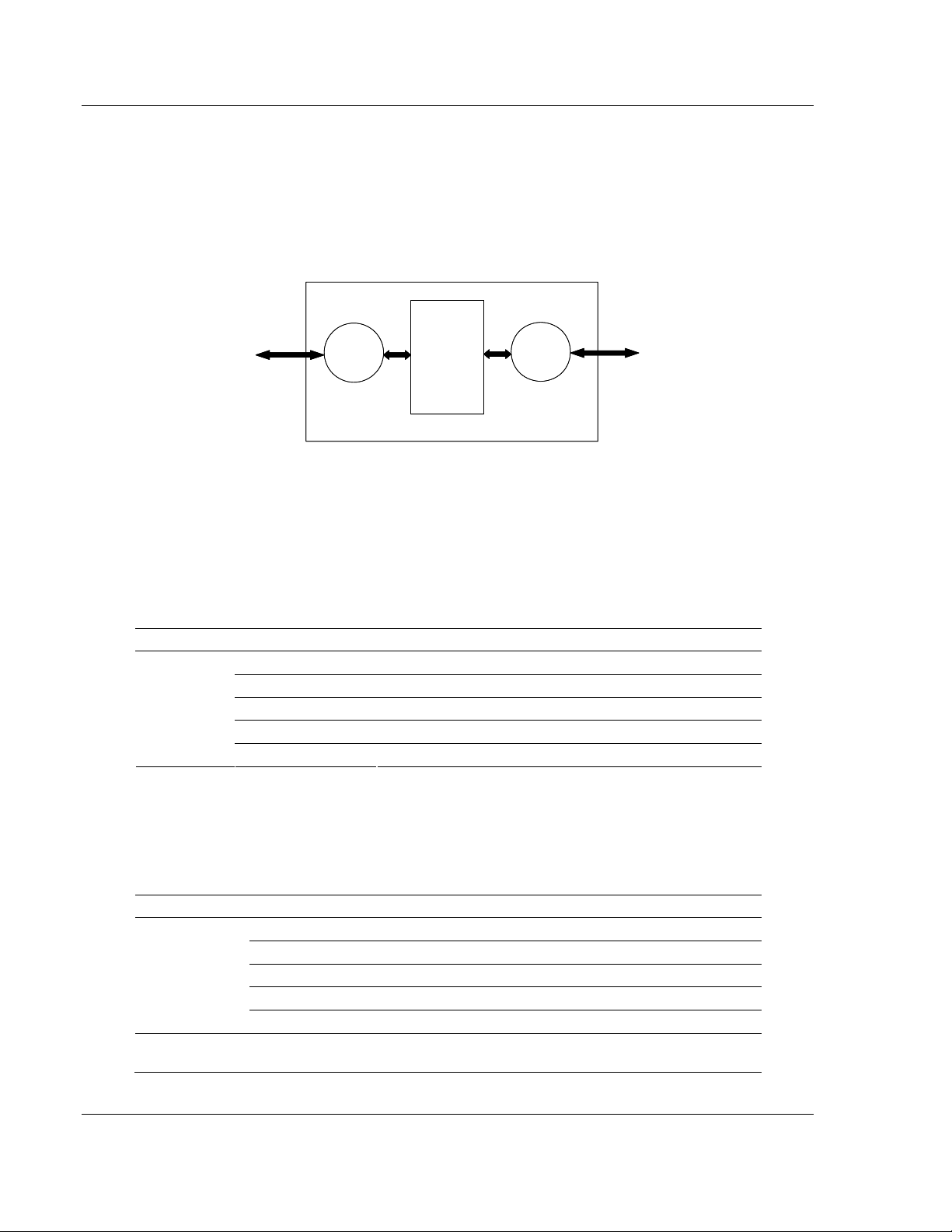
1.1 Module Internal Database
The internal database is central to the functionality of the module. This database
is shared between all the ports on the module and is used as a conduit to pass
information from one device on one network to one or more devices on another
network. This permits data from devices on one communication port/network to
be viewed and controlled by devices on another port/network.
ProLinx
ProLinx
Communication
Communication
Gateways
Other ProLinx
Other ProLinx
Protocol
Protocol
Driver
Driver
Gateways
Internal
Internal
Database
Database
(Up to 4000 regs)
regs)
DNPM
Driver
Driver
1.2 DNP Master Database Layout
Central to the functionality of the DNP driver is the database. This database is
used as the interface between remote DNP devices and the other protocol
implemented on a module. The content and structure of the user data area of the
database is completely user defined. The following illustration shows the general
format of the module’s database:
DATA AREA DATA SIZE
DNP DATA
BINARY INPUTS 1 WORD PER 16 POINTS
ANALOG INPUTS 1 WORD PER POINT
COUNTER DATA 2 WORDS PER POINT
BINARY OUTPUTS 1 WORD PER 16 POINTS
ANALOG OUTPUTS 1 WORD PER POINT
The first word of the module’s database contains the first 16 points of binary input
data (if defined). It is important to understand how the data is mapped to the
database so that it can be accessed by the other protocol. Each DNP data type
has a fixed size. This size is used in conjunction with the number of points
configured for the type to determine the size and location in the database. The
following is an example of a user database with a defined set of point counts:
DATA AREA REGISTERS CFG VALUES
DNP DATA
USER DATA
BINARY INPUTS 0 TO 1 2
ANALOG INPUTS 2 TO 51 50
COUNTER DATA 52 TO 71 10
BINARY OUTPUTS 72 TO 73 2
ANALOG OUTPUTS 74 TO 113 40
REMAINING DATA
114 TO 3999
AREA
Page 8 of 56 ProSoft Technology, Inc.
September 30, 2009
Page 9

Functional Overview DNPM ♦ ProLinx Gateway
p
Driver Manual DNP 3.0 Master
Note that the order of the data types is fixed by the driver. In order to access the
binary input data read from a slave device, registers 0 to 1 are used. To set
analog output data to pass to the driver for remote slaves, registers 74 to 113 are
used. Register 74 contains the value for analog output point 0, and register 113
contains the value for analog output point 39.
The other protocol on the ProLinx module should place data in the binary and
analog output data areas. Values set will be passed by the master driver to slave
units on the network.
The other protocol on the ProLinx module should retrieve the data for the binary
and analog inputs and counters as these are obtained by the master driver from
slave units. This monitored data area should not be altered by the other protocol
on the module.
1.3 DNP Master Driver Data Flow
The DNP Master Driver allows the module to generate read and write commands
issued to slave units on the DNP network. The following flow chart and
associated table describe the flow of data into and out of the module.
Step Description
1
The DNP Master driver receives the configuration information from the Flash memory in
the module. This information configures the serial port and define the Master node
characteristics.
2
The Master Driver issues a read or write command to the DNP Slave’s node address.
The Slave device qualifies the message then issues a response containing the
information requested by the master..
3
After the module accepts the response, the data is immediately transferred to or from the
internal database in the module. If the command is a read command (binary input,
analog input, counter, event, and so on), the data is written to the module database. If
the command is a write command (binary output or analog output), the data is read
directly from the database.
4
Error/Status data are available in a Status Block that can be placed anywhere in the
module’s database. This area can be accessed by the other protocol on the module
using the correct database offset.
DNP
Slaves
Unsolicited
Messages or
Res
Slave
Device
onses
Master
Wri te for DNP Read
Function
Master
Driver
Request
DatabasesDNP
Read for DNP
Write Function
Read
Virtual
Database
Command
List
ProSoft Technology, Inc. Page 9 of 56
September 30, 2009
Page 10

DNPM ♦ ProLinx Gateway Functional Overview
DNP 3.0 Master Driver Manual
Page 10 of 56 ProSoft Technology, Inc.
September 30, 2009
Page 11

Port Physical and Protocol Specifications DNPM ♦ ProLinx Gateway
Driver Manual DNP 3.0 Master
2 Port Physical and Protocol Specifications
In This Chapter
DNP 3.0 Master Port Specifications......................................................11
Serial Port Specifications.......................................................................11
2.1 DNP 3.0 Master Port Specifications
Type Specifications
General Parameters
Internal Database Binary Inputs: 0 to 500 word count
Analog Inputs: 0 to 500 points of analog inpu t data
Counters: 0 to 250 points of counter data
Binary Outputs: 0 to 500 word count
Analog Outputs: 0 to 500 points of analog output
Communication parameters Port 0: Baud Rate: 110 to 115,200 baud
Stop Bits: 1
Data Size: 8 bits
Parity: None
RTS Timing delays: 0 to 65535 milliseconds
DNP Mode DNP 3.0 Master - Level 2
DNP Object Support See Reference chapter for full Object Definition document
DNP Master
Node address 0 to 65534 (software selectable)
Slave count The module supports the definition of up to 40 slave devices
Command count
The module supports the definition of up to 300 user defined
commands to interface with remote slave devices
2.2 Serial Port Specifications
Type Specifications
Serial Ports
Serial Port Cables (DB-9M
Connector)
Port 0 RS-232/422/485: jumper selectable
ProSoft Technology, Inc. Page 11 of 56
September 30, 2009
One DIN to DB-9M cable included per configurable serial port
DB-9M connector
Hardware Handshaking: RTS,CTS,DTR,DSR,DCD
Page 12

DNPM ♦ ProLinx Gateway Port Physical and Protocol Specifications
DNP 3.0 Master Driver Manual
Type Specifications
Serial Port Isolation 2500V RMS port-to-port isolation per
UL 1577.
3000V DC min. port to ground and port to logic power isolation.
Serial Port Protection
Collision Avoidance
RS-485/422 port interface lines TVS diode protected at +/- 27V
standoff voltage.
RS-232 port interface lines fault protected to +/- 36V power on,
+/- 40V power off.
The DNP collision avoidance scheme can be enabled for the
port when more than one slave device is present on the
network and unsolicited messaging is supported.
Page 12 of 56 ProSoft Technology, Inc.
September 30, 2009
Page 13

DNPM Protocol Configuration DNPM ♦ ProLinx Gateway
Driver Manual DNP 3.0 Master
3 DNPM Protocol Configuration
In This Chapter
[DNP Master] .........................................................................................13
[DNP Master Database].........................................................................14
[DNP Master Slave List] ........................................................................15
[DNP Master Commands]......................................................................16
The following topics are excerpted from a configuration file showing typical
examples of the DNPM Port of a CFG file for a DNPM port. Shipped with each
unit (or available from the web) is a default configuration file that can easily form
the basis for a working solution. This file can either be downloaded from the
ProSoft web site at www.prosoft-technology.com, or transferred from the module.
Refer to the ProLinx Reference Guide for information on configuring and
downloading .CFG files to ProLinx modules.
3.1 [DNP Master]
The [DNP Master] section of the CFG file sets the DNP 3.0 port communication
parameters and the protocol specific parameters. The following example and
table lists the parameters defined in this section:
[DNP Master]
Internal ID : 1 #0-65534 identification code for this unit
DNP Database Offset : 2000 #0-3999 Start of DNP data in internal DB
Baud Rate : 19200 #Baud rate for port 110-115200
RTS On : 0 #0-65535 milliseconds before message
RTS Off : 0 #0-65535 milliseconds after message
Min Response Delay : 10 #0-65535 milliseconds before response sent
# Collision Avoidance parameters
Collision Avoidance : N #Use Collision Avoidance (Yes or No)
CD Idle Time : 10 #0-32000 mSec min idle time before transmit
CD Time Before Receive : 12 #0-65535 milliseconds before receive
Variable Name Data Range Description
[DNP Master]
Internal Master ID: 0 to 65534
DNP Database Offset 0 to 3999
Baud Rate:
Baud Rate
from Table
This section header defines the start of the DNP Master
parameter set.
This is the DNP address for the module. All messages
assigned to this address from the master are processed by
the module.
Offset in which to place DNP data. Specifies the start of DNP
data in the internal database.
Port Baud Rate: 300, 600, 1200, 2400, 4800, 9600, 19200,
384 (38400), 576 (57600), 115 (115200)
ProSoft Technology, Inc. Page 13 of 56
September 30, 2009
Page 14

DNPM ♦ ProLinx Gateway DNPM Protocol Configuration
DNP 3.0 Master Driver Manual
Variable Name Data Range Description
RTS On: 0 to 65535
RTS Off: 0 to 65535
Min Response Delay: 0 to 65535
Collision Avoidance Parameters
Collision Avoidance: Yes or No
CD Idle Time: 0 to 32000
CD Time Before
Receive:
0 to 65535
This value represents the number of 1 ms increments to be
inserted between asserting the RTS modem line and the
actual transmission of the data.
This value represents the number of 1 ms increments to be
inserted after the last character of data is transmitted before
the RTS modem line is dropped.
Minimum time between receiving a request and transmitting a
response. Allows master time to disable transmitter on an
RS-485 network.
This parameter defines if the collision avoidance functionality
is to be applied to the port. If the parameter is set to No,
collision avoidance is not used. It will be used if set to Yes. If
collision avoidance is used, it requires a special cable.
Defines the minimum number of milliseconds to wait before
transmitting a message after the CD signal is recognized as
low.
Defines the number of milliseconds to wait before receiving
characters after the CD signal is recognized as high.
3.2 [DNP Master Database]
The [DNP Master Database] section of the CFG file sets the size of each data
type utilized by the module in order to define the database. The example and
following table lists the parameters defined in this section:
[DNP Master Database]
Binary Inputs : 2 #0-500 word count to hold BI data
Analog Inputs : 50 #0-500 points of analog input data
Counters : 10 #0-250 points of counter data
Binary Outputs : 2 #0-500 word count to hold BO data
Analog Outputs : 40 #0-500 points of analog output data
Variable Name Data Range Description
[DNP Master Database]
Binary Inputs: 0 to 500
Analog Inputs: 0 to 500
Counters: 0 to 250
Binary Outputs: 0 to 500
Analog Outputs: 0 to 500
This section defines the database for the module
Number of words for digital input points to configure in the
DNP Master device. Each word contains 16 binary input
points.
Number of analog input points to configure in the DNP
Master device. Each point will occupy a one-word area in the
module memory.
Number of counter points to configure in the DNP Master
device. Each point will occupy a two-word area in the module
memory. This number corresponds to the number of frozen
counters. The application maps the counters to the frozen
counters directly.
Number of words for digital output points to configure in the
DNP Master device. Each word contains 16 binary output
points.
Number of analog output points to configure in the DNP
Master device. Each point will occupy a one word area in the
module memory.
Page 14 of 56 ProSoft Technology, Inc.
September 30, 2009
Page 15

DNPM Protocol Configuration DNPM ♦ ProLinx Gateway
Driver Manual DNP 3.0 Master
3.3 [DNP Master Slave List]
The DNP Master Slave List defines information about each slave that will be
used by the master port. Up to 40 devices can be defined for the master driver.
Each node must have an entry. The following example and tables define the data
required for each node:
[DNP Master Slave List]
# This section is used to store information about each slave to be
# used by the master port. There must be an entry in this table for each
# node to be used in the command list. Two of the parameters in this list
# are coded values:
# Conf Mode ==> 0=Never, 1=Sometimes and 2=Always (select 0).
# Flags is bit coded as follows:
# Bit 0 (decimal 1) ==> Enable the slave
# Bit 1 (decimal 2) ==> Use Unsolicited messaging with this slave
# Bit 2 (decimal 4) ==> Use delay measurement with this slave
# Bit 3 (decimal 8) ==> Auto time synchronization enabled
#
START
# Node DL Conf Conf Conf App Rsp
# Address Mode Timeout Retry Timeout Flags
2 0 1000 0 2000 9
END
Two parameters in the list contain coded values as shown in the example.
Variable Name Value Description
Node Address Node address for slave being defined
Conf Mode 0, 1, or 2 0=Never, 1=Sometimes, 2=Always (Select 0)
Conf Timeout Data Link Layer Confirmation timeout
Conf Retry Data Link Layer Confirmation retry count
App Resp Timeout Application layer timeout
Flags Bit 0 (decimal 1) = Enable the slave
Bit 1 (decimal 2) = Use unsolicited messaging with this slave
Bit 2 (decimal 4) = Use delay measurement with this slave
Bit 3 (decimal 8) = Auto time synchronization enabled
The following table describes the information required for each column of each
record in the slave list section. A record is required for each slave device to be
interfaced with by the module.
Column
1
2
3
Variable
Name
DNP Slave
Address
Data Link
Confirm
Mode
Data Link
Confirm
Timeout
Data Range Description
0 to 65534
Coded Value (0=Never,
1=Sometimes,
2=Always).
1 to 65535 milliseconds
This is the slave address for the unit to
override the default values.
This value specifies if data link frames sent
to the remote device require a data link
confirm. This parameter should be set to
zero for almost all applications.
This parameter specifies the time to wait for
a data link confirm from the remote device
before a retry is attempted.
ProSoft Technology, Inc. Page 15 of 56
September 30, 2009
Page 16

DNPM ♦ ProLinx Gateway DNPM Protocol Configuration
DNP 3.0 Master Driver Manual
Column
4
5
6 Slave Mode
Variable
Name
Maximum
Retries for
Data Link
Confirm
Application
Layer
Response
Timeout
Data Range Description
0 to 255 retries
1 to 65535 milliseconds
Coded Value (Bit 0 =
Enable, Bit 1 = Unsol
Msg, Bit 2 = Use DM, Bit
3 = Auto Time Sync).
Maximum number of retries at the Data Link
level to obtain a confirmation. If this value is
set to 0, retries are disabled at the data link
level of the protocol. This parameter is only
used if the frame is sent with confirmation
requested.
Time-out period the master will wait for each
response message fragment. If data link
confirms are enabled, make sure the timeout
period is set long enough to permit all data
confirm retries.
This word contains bits that define the slave
mode. The slave mode defines the
functionality of the slave device and can be
combined in any combination. The fields
have the following definition: Enable:
determines if this slave will be used. Unsol
Msg: causes an enabled unsolicited
response message to be sent to the slave
when its RESTART IIN bit is set. This
parameter is also required for unsolicited
message reporting by the IED unit. Use DM:
uses delay measurement. Auto Time Sync:
time synchronization used when NEED TIME
IIN bit set.
3.4 [DNP Master Commands]
The DNP Master Commands section contains the list of commands to process
on the master port. Up to 300 commands can be defined in this section to
monitor and control all the slave devices on the network. Node addresses in the
command list must contain an entry in the [DNP Slave List]. The following
example and table define the data required for each command:
[DNP Master Commands]
# This section contains the list of commands to process on the master port.
# Node addresses present in the command list must have an entry in the
# [DNP Slave List]. Commands with nodes not present in the list will not be
# executed.
#
START
# 1 2 3 4 5 6 7 8 9
#Flags/ Node Data Data Cmd Device Point IED DB Poll
#Enable Address Object Variation Func Address Count Address Interval
6 2 1 0 1 0 -32 0 0
6 2 -12 257 3 0 2000 0 10
6 2 20 0 1 0 5 0 0
6 2 30 0 1 0 -50 0 0
6 2 41 2 5 0 4 0 0
END
Page 16 of 56 ProSoft Technology, Inc.
September 30, 2009
Page 17

DNPM Protocol Configuration DNPM ♦ ProLinx Gateway
Driver Manual DNP 3.0 Master
Variable Name Value Description
Flags Enable See discussion that follows
Node Address
Data Object
Data Variation This is the DNP data variation for the command
Cmd Func
Device Address
Point Count
IED DB Address
Poll Interval
Specifies the node address of the slave unit for which the
command is to be sent
This is the DNP data object code for the command (For
issuing a CROB command refer to the following discussion).
This is the DNP command code to be used when forming the
command request
This is the starting address in the device (point address) for
the command
This field defines the number of points to request from the
slave device. If the parameter is set to a negative number
(-n), the module will only process the first -n number of
points. For example, if this field is set to -3, only the first 3
points will be accepted into the database.
This field defines the internal address in the master driver's
database to be associated with the command. If the
command is a read command, the data read will be placed at
this address. If the command is a write command, the data to
be written will be sourced from this address.
This field specifies the minimum number of seconds to wait
between the issuance of the command.
The value for the Flags/Enable and point count are dependent on the type of
function (input or output) being executed by the module. The two diagrams
display this relationship:
Inputs:
Port/Flags
Bits
0 Not Used
1 Communication Port (1=DNP Master Port) 2
2 Enable/Disable Command (1=Enable, 0=Disable) 4
3 to 7 Not Used
If # of Points < 0, then use Qual 06h (all points, packaged & -Points = # of points to consider)
If Address in Slave = 0 & # of Points > 0, then use Qual 00h or 01h (points 0 to # of points -1)
If Address in Slave > 0 & # of Points > 0, then use Qual 00h or 01h (address to address+# of
points-1)
Description
Decimal
Equivalent
Outputs:
Port/Flags
Bits
0 Not Used
1 Communication Port (1=DNP Master Port) 2
2 Enable/Disable Command (1=Enable, 0=Disable) 4
3 Poll Type (0=Poll, 1=Exception) 8
4 to 7 Not Used
Description
Decimal
Equivalent
ProSoft Technology, Inc. Page 17 of 56
September 30, 2009
Page 18

DNPM ♦ ProLinx Gateway DNPM Protocol Configuration
DNP 3.0 Master Driver Manual
Port/Flags
Description
Bits
If Address in Slave = 0 & # of Points > 0, then use Qual 17h or 28h (# of points specified starting at
point 0)
If Address in Slave > 0 & # of Points > 0, then use Qual 17h or 28h (points from address to
address+# of points-1)
If # of Points <= 0, then ignore because this is illegal for outputs.
Decimal
Equivalent
Other rules that must be observed when constructing commands are as follows:
Address in Slave: This value must be >= 0. If it is set to a value < 0, the
command will be ignored.
Point Count: This value must be set to a value other than 0. If the value is set to
0, the command will be ignored.
Poll Interval: 0=Continuous, >0=Number of seconds between polls. If exception
processing is used for output commands, this parameter is ignored, and the
command will only be issued when data changes.
The following two examples of commands display the interrelationship of the
parameters used to construct a command:
BINARY INPUT COMMAND EXAMPLES:
WORD 012345678
VALUE 6 21010 32 00
Address Address
Port/Flg Slave Object Var Func Addr Pnt Cnt IED DB Poll Int
Command for DNP Master Port, Enabled.
IED #15 IED BI's
00
31 31
IED Unit 2 is to be polled.
Object type is 1 (Binary Input).
Variation of 0 (default variation).
Function 1 is for a read.
Point address 0 Is starting address in IED device
Point count of 32 indicates points 0-31 to be
polled.
IED DB address of 0 is where first data point is
placed. (within BI database)
Poll command as soon as possible.
BINARY OUTPUT COMMAND EXAMPLES:
WORD 0 1 2 3 4 5 6 7 8
VALUE 14
Address Address
Port/Flg Slave Object Var Func Addr Pnt Cnt IED DB Poll Int
2
IED #15 IED BO's
0
15
12 1 5 0 16 25 0
Command for Port 2, Enabled, only operate on
point change.
IED Unit 2 is to be controlled.
0
15
Object type is 12 (Binary Output Control).
Variation of 1 (Control Relay Output
Block).
Function 5 is for direct operate.
Slave address of 0 is starting point in IED.
16 points are transferred.
IED DB address of 0 is first source point.
Command not a polled command.
Write only on change of data in BO database.
Page 18 of 56 ProSoft Technology, Inc.
September 30, 2009
Page 19

DNPM Protocol Configuration DNPM ♦ ProLinx Gateway
Driver Manual DNP 3.0 Master
Note: CROB commands (object 12) exceeding a count of 16 are not recommended. Many IEDs
only support one transport layer and a count > 16 may cause the IED device to not accept the new
data value being written by the ProLinx module.
The following table aids in defining the command list as it displays the values
required for certain DNP data types:
Digital input Digital input Events Digital Output Counter
0 Port/Flags Port/Flags Port/Flags Port/Flags
1 Slave Address Slave Address Slave Address Slave Address
2 1 2 12 20
3 0, 1 or 2 0, 1, 2 or 3 1* 0, 5 or 6
4 1* 1* 3, [4], 5 or 6 1, 7, 8, 9 or 10
5 Address in Slave Address in Sla v e Address in Slave Address in Slave
6 # of Points # of Points # of Points # of Points
7 IED DB Address IED DB Address IED DB Address
8 Poll Interval Poll Interval Poll Interval Poll Interval
Frozen Counter Analog Input Analog Input Events Analog Output
0 Port/Flags Port/Flags Port/Flags Port/Flags
1 Slave Address Slave Address Slave Address Slave Address
2 21 30 32 41
3 0, 9 or 10 0, 1, 2, 3 or 4 0, 1, 2, 3 or 4 2*
4 1* 1* 1* 3, [4], 5 or 6
5 Address in Slave Address in Slave Address in Slave Address in Slave
6 # of Points # of Points # of Points # of Points
7 IED DB Address IED DB Address IED DB Address
8 Poll Interval Poll Interval Poll Interval Poll Interval
Time and Date Class 0 Class 1 Class 2
0 Port/Flags Port/Flags Port/Flags Port/Flags
1 Slave Address Slave Address Slave Address Slave Address
2 50 60 60 60
3 1* 1 2 3
4 2*
5
6 1 1 1 1
7
8 Poll Interval Poll Interval Poll Interval Poll Interval
ProSoft Technology, Inc. Page 19 of 56
September 30, 2009
Page 20

DNPM ♦ ProLinx Gateway DNPM Protocol Configuration
DNP 3.0 Master Driver Manual
Class 3 Cls 1, 2 & 3 Cls 0, 1, 2 & 3 [Clear Restart Bit]
0 Port/Flags Port/Flags Port/Flags Port/Flags
1 Slave Address Slave Address Slave Address Slave Address
2 60 60 60 80
3 4 5 6 1
4 2
5 7
6 1 1 1 1
7
8 Poll Interval Poll Interval Poll Interval
Cold Restart Warm Restart Enable Unsol. Msg Disable Unsol. Msg
0 Port/Flags Port/Flags Port/Flags Port/Flags
1 Slave Address Slave Address Slave Address Slave Address
2 0 0 0 0
3
4 13 14 20 21
5
6 1 1 1 1
7
8
Word Offset Definitions
* Value Assumed 0 Port/Flags
[ ] Automatically implemented 1 Slave Address
2 Object
3 Variation
4 Function
5 Address in Slave
6 Point Count
7 IED DB Address
8 Poll Interval
Page 20 of 56 ProSoft Technology, Inc.
September 30, 2009
Page 21

DNPM Protocol Configuration DNPM ♦ ProLinx Gateway
Driver Manual DNP 3.0 Master
A special data type is added to the module in order to generate CROB
commands to control binary outputs. The following table shows the format to be
utilized when this command is desired:
Column Definitions Description
1 Port/Flags Set this parameter to 6 to enable the command in the list.
2 Slave Address
3 Object Object type always -12
4 CROB Image (L)
Pulse Count (H)
5 Function
6 Address in Slave Point in IED to consider with the CROB.
7 Pulse Time
8 DB Address
9 Poll Interval
This is the IED node address for the slave to consider on the
network.
The CROB Image parameter contains the CROB image for
the command. Refer to the following table for the definition of
this block.
The pulse count parameter specifies the number of pulses to
generate for pulse output control. This parameter has a range
of 0 to 255 as the value is a byte parameter in the CROB. If a
value of zero is entered, the operation will not execute.
Function codes 3, 5 and 6 supported. Function code 4 is
automatically sent after a successful function 3.
This parameter sets the on and off time to use if the pulse
operation is to associate with this command.
This is address in the module's internal database to use as a
trigger for the command. If a value other than 0 is found in the
register, the command will be executed. The database register
will be set to 0 after the command is placed in the command
queue.
This field specifies the minimum number of seconds to wait
between the issuance of the command.
The value for the CROB image is that specified in the DNP specification. The
following table lists the bits that comprise this value:
Bits Definitions Description
0 to 3 Code
4 Queue
5 Clear
6 to 7 Trip/Close
These bits determine the control operation to be performed by
the command: 0=No operation, 1=Pulse on, 2=Pulse off,
3=Latch on and 4=Latch off. All other values are undefined in
the DNP protocol.
0=Normal (execute once), 1=Requeue (place at end of queue
after operation).
This parameter clears the queue. If the value is set to zero,
the queue is not affected. If the value is set to 1, the queue will
be cleared.
These two bits select the trip or close relay. For close relay
control, set the bits to 01. For trip relay control, set the bits to
10. A value of 00 for the bits is used for single point control of
normal digital output points.
ProSoft Technology, Inc. Page 21 of 56
September 30, 2009
Page 22

DNPM ♦ ProLinx Gateway DNPM Protocol Configuration
DNP 3.0 Master Driver Manual
Example 1 – Digital Output
No CROB Control - Does not allow full control of Control Operation, Queue,
Clear, Trip/Close, and Pulse count. Only Latch On/Off supported and count is set
1, on and off time set to zero, 1 and status set to zero.
1
2
3 12
4
5
6
7
8
9 Low byte of parameter value is used as Pol l Interval
Example 2 – Digital Output
For Select (and implied operate).
With CROB control - Allows full control of Control Operation, Queue, Clear,
Trip/Close and Pulse count.
1
2
3 -12
4 Lo byte of parameter value is object variation
5 3, [4]
6
7
8
9 Low byte of parameter value is used as Pol l Interval
Example 3 – Digital Output
For Direct Operate (with/without rack).
With CROB control - Allows full control of Control Operation, Queue, Clear,
Trip/Close, and Pulse/count.
1
2
3 -12
4 Low byte is object variation. High byte = Pulse count = 1
5 Low byte = Function (5 or 6)
6
7
8
9 Not used.
Page 22 of 56 ProSoft Technology, Inc.
September 30, 2009
Page 23

DNPM Protocol Configuration DNPM ♦ ProLinx Gateway
Driver Manual DNP 3.0 Master
Besides issuing commands to slave devices, the command list is also used to
map data received in event messages to the proper database locations. For
example, Slave 1 and Slave 1 both possess binary point 0. When an event from
each slave is received, the data entered into the command list is utilized to place
the data for the two events in the correct database location. When the command
list is read by the module is forms lists for each slave relating the address in the
device to that in internal database of the module. The following illustration shows
how the module stores this data:
SLAVE LIST
Address Address Address
DNP Data DNP Data DNP Data
Comm Data Comm Data Comm Data
Next Ptr Next Ptr Next Ptr Null
DI | AI | C DI | AI | C DI | AI | C
DI Pnts Null Cntr Pnts DI Pnts Null Cntr Pnts DI Pnts AI Pnts Null
DI Pnts Cntr Pnts DI Pnts Null DI Pnts AI Pnts
Null Cntr Pnts DI Pnts Null AI Pnts
Null Null Null
DI Pnts are generated for each command with an object type of 1.
AI Pnts are generated for each command with an object type of 30.
Cntr Pnts are generated for each command with an object type of 20 or 21.
The point lists are used by the module to determine the destination of all data
read by the module from the IED's. When the master receives a poll response or
an unsolicited response message, the points in the message are mapped to the
IED database using the point lists. For example, when the master receives a
value for binary input point 10 from slave unit 14, the following steps are
performed by the module:
1 First the module searches the slave list to make sure slave 14 is valid for the
module. If the slave not found the message is ignored. If the slave is found,
the module saves the pointer to the binary input point list.
2 Point number 10 is searched for in the binary input point list. If the point is
found in the DNP point list, the new value is stored at the correct offset in the
BI database. If the point is found in the IED point list, the new value is stored
at the correct offset in the IED database. If the point is not found in either
point list, it is ignored.
Each node in the point lists contain the start-stop IED point ranges and the IED
database offset values. These values are read by the module from the command
list each time the module performs the restart operation. If the database address
value is set to -1, the database is not used for the specified point range.
When the lists are formed by the module, the enable/flag field is ignored.
Therefore, you can place commands that will not be executed in the command
list and are only used for data mapping.
ProSoft Technology, Inc. Page 23 of 56
September 30, 2009
Page 24

DNPM ♦ ProLinx Gateway DNPM Protocol Configuration
DNP 3.0 Master Driver Manual
Page 24 of 56 ProSoft Technology, Inc.
September 30, 2009
Page 25

Communication Port Cables DNPM ♦ ProLinx Gateway
Driver Manual DNP 3.0 Master
4 Communication Port Cables
In This Chapter
DNP 3.0 Master Port .............................................................................25
Port 0, 1, 2, 3: RS-232 - Null Modem (DTE with Hardware Handshaking)26
Port 0, 1, 2, 3: RS-232 - Null Modem (DTE without Hardware
Handshaking)........................................................................................
Port 0, 1, 2, 3: RS-232 - DTE to DCE Modem Connection....................27
Collision Avoidance (DNP modules only)..............................................28
Port 0, 1, 2, 3: RS-422 Interface Connections.......................................29
Port 0, 1, 2, 3: RS-485 Interface Connections.......................................29
This section contains information on the cable and pin assignments for the
ProLinx module's serial ports (RS-232/422/485). The ProLinx module will come
with one to five serial ports, depending on the configuration purchased. In all
cases, the protocol serial ports will have the same pinouts.
27
Example: The 5202-MNET-MCM4 module contains five serial communication ports; four
configurable protocol application ports and one Configuration/ Debug port.
The 5201-MNET-MCM module contains two serial communication ports; one configurable protocol
application port and one Configuration/Debug port.
Each physical serial port has an eight-pin Mini-DIN jack connector. A six-inch
Mini-DIN-8Male to DB-9Male adapter cable is provided for each serial port. The
DB-9M provides connections for RS-232, wired as Data Terminal Equipment
(DTE), RS-422 and RS-485. The diagrams in the following topics detail the pin
assignments for several possible electrical interface connections.
4.1 DNP 3.0 Master Port
ProSoft Technology, Inc. Page 25 of 56
September 30, 2009
Page 26

DNPM ♦ ProLinx Gateway Communication Port Cables
DNP 3.0 Master Driver Manual
The ProLinx module supports the DNP 3.0 protocol as a Master on one port. This
port is fully configurable.
The relationship between the port labeling on the front of the ProLinx module and
the application is as follows:
Port Label Function
Debug Debug/Configuration
Port 0 DNP Master Port
Following ports only exist on multiple port units
Port 1 Not available to DNP Driver
Port 2 Not available to DNP Driver
Port 3 Not available to DNP Driver
The DNP Master port can be used to continuously interface with a DNP slave
devices over a serial communication interface (RS-232, RS-422 or RS-485).
4.2 Port 0, 1, 2, 3: RS-232 - Null Modem (DTE with Hardware Handshaking)
This type of connection is used when the device connected to the module
requires hardware handshaking (control and monitoring of modem signal lines;
Use CTS parameter set to Y
ES).
Page 26 of 56 ProSoft Technology, Inc.
September 30, 2009
Page 27

Communication Port Cables DNPM ♦ ProLinx Gateway
Driver Manual DNP 3.0 Master
4.3 Port 0, 1, 2, 3: RS-232 - Null Modem (DTE without Hardware
Handshaking)
This type of connection can be used to connect the module to a computer or field
device communication port.
Note: If the port is configured with the Use CTS set to YES, then a jumper is required between the
RTS and the CTS line on the module connection.
4.4 Port 0, 1, 2, 3: RS-232 - DTE to DCE Modem Connection
This type of connection is required between the module and a modem or other
communication device.
The Use CTS Line parameter for the port configuration should be set to Y
most modem applications.
ProSoft Technology, Inc. Page 27 of 56
September 30, 2009
ES for
Page 28

DNPM ♦ ProLinx Gateway Communication Port Cables
DNP 3.0 Master Driver Manual
4.5 Collision Avoidance (DNP modules only)
The RTS line is controlled by the RTS on and off parameters set for the port. If
the CTS line is used (usually only required for half-duplex modems and not
defined for use in the DNPS specification), the RTS and CTS lines must either be
connected together or connected to the modem. The following illustration shows
the cable required when connecting the port to a modem.
If collision avoidance is used in a point-to-point connection on the RS-232
interface, the following cable should be used.
Page 28 of 56 ProSoft Technology, Inc.
September 30, 2009
Page 29

Communication Port Cables DNPM ♦ ProLinx Gateway
Driver Manual DNP 3.0 Master
4.6 Port 0, 1, 2, 3: RS-422 Interface Connections
The following illustration applies when the RS-422 interface is selected.
4.7 Port 0, 1, 2, 3: RS-485 Interface Connections
The following illustration applies when the RS-485 interface is selected.
NOTE: This type of connection is commonly called a RS-485 half-duplex, 2-wire connection. If you
have RS-485 4-wire, full-duplex devices, they can be connected to the module's serial ports by
wiring together the TxD+and RxD+ from the two pins of the full-duplex device to Pin 1 on the
module and wiring together the TxD- and RxD- from the two pins of the full-duplex device to Pin 8
on the module. As an alternative, you could try setting the module to use the RS-422 interface and
and connect the full-duplex device according to the RS-422 wiring diagram (page 29). For
additional assistance, please contact ProSoft Technical Support.
ProSoft Technology, Inc. Page 29 of 56
September 30, 2009
Page 30

DNPM ♦ ProLinx Gateway Communication Port Cables
DNP 3.0 Master Driver Manual
Page 30 of 56 ProSoft Technology, Inc.
September 30, 2009
Page 31

LED Indicators DNPM ♦ ProLinx Gateway Driver Manual DNP 3.0 Master
5 LED Indicators
In This Chapter
Common module LEDs .........................................................................31
LEDs for Port 0 Serial Port....................................................................31
4101 Series LEDs .................................................................................32
Troubleshooting the operation of the DNP Master port can be performed using
several methods.
The first and quickest is to scan the LEDs on the module to determine the
existence and possibly the cause of a problem. This section provides insight into
the operation of the Serial Port status LEDs. Information on the module’s other
LEDs can be found in the ProLinx Reference Guide.
5.1 Common module LEDs
LED State Description
Power
Err
Off
Green Solid
Off Normal operation. Fault
Red Solid
Off Normal operation. Cfg
Amber Solid
Off Normal operation.
Flashing
Solid Red
Power is not connected to the power terminals or source is insufficient
to properly power the module (800mA at 24vdc minimum required)
Power is connected to the power terminals. Verify that the other LEDs
for operational and functional status come on briefly after power-up
(check for burned-out LEDs).
A critical error has occurred. Program executable has failed or has
been user-terminated and is no longer running. Press Reset p/b or
cycle power to clear error. If not, use the Debug procedures described
later in this manual.
The unit is in configuration mode. The configuration file is currently
being downloaded or, after power-up, is being read, the unit is
implementing the configuration values, and initializing the hard ware.
This will occur during power cycle, or after pressing the reset button. It
also occurs after a cold/warm boot command is received.
An error condition has been detected and is occurring on one of the
application ports. Check configuration and troubleshoot for
communication errors.
This error flag is cleared at the start of each command attempt
(master/client) or on each receipt of data (slave/adapter/server); so, if
this condition exists, it indicates a large number of errors are occurring
in the application (due to bad configuration) or on one or more ports
(network communication failures).
ProSoft Technology, Inc. Page 31 of 56
September 30, 2009
Page 32

DNPM ♦ ProLinx Gateway LED Indicators
DNP 3.0 Master Driver Manual
5.2 LEDs for Port 0 Serial Port
Some ProLinx modules have three extra serial ports. Each of these serial ports
has two LEDs indicating status.
LED Color Description
Off No activit y on the port. Port 0 - ACT
Green Flash The port is either actively transmitting or receiving data
Port 0 - ERR
Off
Red On or Flashing
Normal state. When off and Port Active led is indicating
activity, there are no communication errors
Activity on this led indicates some communication error
was detected, either during transmit or receive
5.3 4101 Series LEDs
LED State Description
Off Power is not connected to the power terminals. Power
Green Solid
Off Normal operation. Fault
Red Solid
Off Normal operation. CFG
Amber Solid
ERR
Off Normal operation.
Flashing
Solid Red
Power is connected to the power terminals. Verify that the other LEDs
for operational and functional status light.
The Debug/Configuration mode is active (applies to modules that
support pass-through on Debug port - such as DFCM units).
If CFG LED is not on, a critical error has occurred. Program executable
has failed or has been user-terminated and is no longer running. Press
Reset p/b or cycle power to clear error. If not, use the Debug
procedures described later in this manual.
If Fault LED is on, the Debug/Configuration Mode is active (if the
module supports pass-through on the Debug port - such as DFCM
units).
If the Fault LED is off, the unit is in the configuration mode. The
configuration file is being read and the unit is implementing the
configuration values and initializing the hardware. This will occur during
power cycle, or after pressing reset button. It also occurs after a
cold/warm boot command is received.
An error condition has been detected and is occurring. Check
configuration.
This condition is indicative of a large number of errors in the application
interface communications. The module's error flag is cleared at the
start of each command (master/client) or receipt of data
(slave/adapter/server).
Page 32 of 56 ProSoft Technology, Inc.
September 30, 2009
Page 33

Reference DNPM ♦ ProLinx Gateway
Driver Manual DNP 3.0 Master
6 Reference
In This Chapter
Error Codes...........................................................................................33
Device Profile........................................................................................37
Subset Definition...................................................................................39
Command List Entry Form.....................................................................45
6.1 Error Codes
6.1.1 Module Error Codes
These error codes are generated by the module in response to communication
problems on an emulated slave port or configuration errors. Review the error list
to view the last set of 60 errors generated by the module. The error codes are
listed in the following tables:
Slave Port Communication Errors
Error Code Name Description
0 OK
10
11
12
13
14
15
16
17
18
19
DNP synchronization error
(Physical Layer Error)
DNP overrun error (Physical
Layer Error)
DNP length error (Physical
Layer Error)
DNP bad CRC error (Data
Link Layer Error)
DNP user data overflow
error (Transport Layer Error)
DNP sequence error
(Transport Layer Error)
DNP address error
(Transport Layer Error)
DNP bad function code
error (Application Layer
Error)
DNP object unknown error
(Application Layer Error)
DNP out of range error
(Application Layer Error)
The module is operating correctly and there are no
errors.
Extra bytes are received before the start bytes (0x05
and 0x64).
Mainline Data Link Layer routine could not read data
received on DNP port before it was overwritten.
Length of message does not match length value in
message.
Computed CRC value for message does not match
that received in message.
Application layer received a message fragment buffer
which is too small.
Sequence numbers of multi-frame request fragments
do not increment correctly.
Source addresses contained in multi-frame request
fragments do not match.
Function code received from DNP master is not
supported for selected object/variation.
Slave does not have the specified objects or there are
no objects assigned to the requested class.
Qualifier, range or data fields are not valid or out of
range for the selected object/variation.
ProSoft Technology, Inc. Page 33 of 56
September 30, 2009
Page 34

DNPM ♦ ProLinx Gateway Reference
DNP 3.0 Master Driver Manual
Error Code Name Description
20
21
System Configuration Errors
Error Code Name Description
100
101
102 Too many counter points
103
104
105
106
107
108 Not enough memory
109
110 File count invalid The file count must be in the range of 0 to 6.
111 Invalid file record size The file record size must be in the range of 1 to 120.
112
DNP Port Configuration Errors
Error Code Name Description
212 Invalid DNP address
213 Invalid DNP port baud rate
219
220
222
223
224
DNP message overflow
error (Application Layer
Error)
DNP master multi-frame
message error (Application
Layer Error)
Too many binary input
points
Too many binary output
points
Too many analog input
points
Too many analog input
points
Too many binary input
events
Too many analog input
events
Invalid analog input
deadband
Invalid block transfer delay
for blocks 251 and 252
(error/status blocks)
Invalid block identification
code for file
Invalid DNP data link layer
confirm mode
Invalid DNP data link
confirm time-out
Invalid DNP select/operate
arm time duration
Invalid DNP application
layer confirm time-out
Invalid DNP write time
interval
Application response buffer overflow condition. The
response message from the slave is too long to
transmit.
Received a multi-frame message from the DNP
master. This application does not support multi-frame
messages from the master.
Too many binary input points are configured for the
module. Maximum value is 15360.
Too many binary output points are configured for the
module. Maximum value is 15360.
Too many counter points are configured for the
module. Maximum value is 480.
Too many analog input points are configured for the
module. Maximum value is 960.
Too many analog output points are configured for the
module. Maximum value is 960.
Too many binary input events are configured for the
module. Maximum value is 400.
Too many analog input events are configured for the
module. Maximum value is 400.
Deadband value for analog input events is out of
range. Value must be in the range of 0 to 32767.
There is not enough memory in the module to
configure the module as specified.
Block transfer delay value specified is too low.
The file block transfer code must be in the range of
100 to 120.
The DNP address specified in the configuration is not
valid (0 to 65534).
The baud rate code specified in the configuration is
not valid.
The data link confirmation mode code is not valid in
the configuration.
The data link time-out period specified in the
configuration is 0. It must be an integer in the range of
1 to 65535.
The select/operate arm timer is set to 0. It must be an
integer in the range of 1 to 65535.
The application layer confirm time-out value is set to 0.
It must be an integer in the range of 1 to 65535.
The write time interval is not in the data range in the
configuration. The value must be in the range of 0 to
1440.
Page 34 of 56 ProSoft Technology, Inc.
September 30, 2009
Page 35

Reference DNPM ♦ ProLinx Gateway
Driver Manual DNP 3.0 Master
Error Code Name Description
225
226
227
228
230
Invalid DNP unsolicited
response mode
Invalid DNP unsolicited
response minimum quantity
for Class 1
Invalid DNP unsolicited
response minimum quantity
for Class 2
Invalid DNP unsolicited
response minimum quantity
for Class 3
Invalid DNP unsolicited
response destination
address
The unsolicited response mode code is not valid in the
configuration.
The unsolicited response minimum quantity for Class
1 is not valid in the configuration. Value must be an
integer in the range of 1 to 255.
The unsolicited response minimum quantity for Class
2 is not valid in the configuration. Value must be an
integer in the range of 1 to 255.
The unsolicited response minimum quantity for Class
3 is not valid in the configuration. Value must be an
integer in the range of 1 to 255.
The unsolicited response destination address is not
valid in the configuration. Value must be in the range
of 1 to 65534.
6.1.2 Command Error Codes
Command error codes are generated by the module's program. These errors are
generated when an error occurs when issuing a request or processing a
response of a command list function. The following tables list the command error
codes used in the module:
General Command Errors
Error Code Name Description
1 Device not defined
2 Invalid command
3 Object not supported
4
10
11
20
30
31
40
50
51
Command function not
supported
Invalid binary input poll
command
Invalid binary input event
poll command
Invalid binary output
command function
Invalid counter poll
command function
Invalid counter poll
command
Invalid frozen counter poll
command
Invalid analog input poll
command
Invalid analog input event
poll command
The IED slave address referenced in the command is
not defined in the module. Check to make sure there is
an entry in the slave table for each slave device
referenced in the command list.
This command is not valid. Check to make sure the
slave address parameter is greater than or equal to
zero and that the point count is not set to zero.
The data object in the command is not supported by
the module. Refer to the DNP subset for the Master
Port.
The function specified in the command is not
supported for the object type selected. Refer to the
DNP subset for the Master Port.
This binary input object command is not valid.
This binary input event object poll command is not
valid.
This binary output command function is not valid.
The counter object poll command contains an invalid
function code.
This counter object poll command is not valid.
This frozen counter object poll command is not valid.
This analog input poll command is not valid.
This analog input event poll command is not valid.
ProSoft Technology, Inc. Page 35 of 56
September 30, 2009
Page 36

DNPM ♦ ProLinx Gateway Reference
DNP 3.0 Master Driver Manual
Error Code Name Description
60
61
70
80 Invalid event poll command This event poll command is not valid.
Application Layer Errors
Error Code Name Description
1000 Device index invalid
1001
1002
1003 Sequence number error
1004
1005
1006
1007
1008
1009
1010
Invalid analog output poll
command function
Invalid analog output poll
command
Invalid time/date poll
command
Duplicate request in
application layer queue
COM port device removed
from system
Response to select before
operate does not match
Response does not contain
date/time object
Time-out condition on
response
Function code in application
layer message not
supported
Read operation not
supported for
object/variation
Operate function not
supported for the
object/variation
Write operation not
supported for the
object/variation
This analog output poll command contains an invalid
function code.
This analog output poll command is not valid.
This time/date object poll command is not valid.
The device index in the request or response message
is not found in the slave list.
The newly submitted message to the application layer
already exists in the queue. The message is ignored.
The communication port for the message has been
uninstalled on the system. This error should never
occur as the communication ports are only uninstalled
when the module's program is terminated.
The application sequence number in the response
message does not match that based on the last
request message. This indicates application layer
messages are received out of order.
The select response message received from the slave
module is not that expected from the last select
request. This indicates a synchronization problem
between the master and slave devices.
The response message from the slave device does
not contain a date/time object. The master expects this
object for the response message.
The slave device did not respond to the last request
message from the master within the time-out set for
the IED device. The application layer time-out value is
specified for each IED unit in the slave configuration
table in the module. This table is established each
time the module performs the restart operation.
The function code returned in the response message
is not valid for the application layer or not supported by
the module.
The application layer response message contains an
object that does not support the read function.
The application layer response message contains an
object that does not support the operate function.
The application layer response message contains an
object that does not support the write function.
Use the error codes returned for each command in the list to determine the
success or failure of the command. If the command fails, use the error code to
determine the cause of failure.
Page 36 of 56 ProSoft Technology, Inc.
September 30, 2009
Page 37

Reference DNPM ♦ ProLinx Gateway
Driver Manual DNP 3.0 Master
6.2 Device Profile
DNP V3.00
DEVICE PROFILE DOCUMENT
Vendor Name: ProSoft Technology, Inc.
Device Name: DNP MASTER (VERSION 2.20)
Highest DNP Level Supported : Device Function:
For Request: L2 Master
For Responses: L2
Notable objects, functions, and/or qualifiers supported in addition to the highest DNP level stated above (see
attached table for complete list):
The following features are configurable on the module: Collision avoidance
Maximum Data Link Frame Size (octets): Maximum Application Fragment Size (octets):
Transmitted : 292 Transmitted : 2048
Received : 292 Received : 2048
Maximum Data Link Re-tries: Maximum Application Layer Re-tries:
Configurable from 0 - 255 None
Requires Data Link Layer Confirmation:
Configurable at module start-up (never, sometimes, & always)
Requires Application Layer Confirmation:
ProSoft Technology, Inc. Page 37 of 56
September 30, 2009
Page 38

DNPM ♦ ProLinx Gateway Reference
DNP 3.0 Master Driver Manual
Page 38 of 56 ProSoft Technology, Inc.
September 30, 2009
Page 39

Reference DNPM ♦ ProLinx Gateway
Driver Manual DNP 3.0 Master
6.3 Subset Definition
OBJECT REQUEST RESPONSE
Obj Var Description Func
Codes
1 0 Binary Input: All
Variations
1 Binary Input 1 06 129,
2 Binary Input with
Status
2 0 Binary Input
Change: All
Variations
1 Binary Input
Change Without
Time
2 Binary Input
Change With Time
3 Binary Input
Change With
Relative Time
10 0 Binary Output: All
Variations
1 Binary Output
2 Binary Output
Status
12 0 Control Block: All
Variations
1 Control Relay
Output Block
2 Pattern Control
Block
3 Pattern Mask
20 0 Binary Counter: All
Variations
1 32-Bit Binary
Counter
2 16-Bit Binary
Counter
3 32-Bit Delta
Counter
4 16-Bit Delta
Counter
5 32-Bit Binary
Counter Without
Flag
1 06
1 06 129,
1 06, 07, 08
1 06, 07, 08
1 06, 07, 08 129,
1 06, 07, 08 129,
1 06
3, 4, 5, 6 17, 28 129 Echo of
1, 7, 8,
9, 10
1, 7, 8,
9, 10
Qual
Codes
(hex)
129,
06
129,
129,
129,
129,
06 129,
Func
Codes
130
130
129,
130
130
130
130
130
130
130
130
130
Qual
Codes
(hex)
1 Master will generate this variation
00, 01 1 Master will generate and process this
00, 01 8 Master will generate and process this
56 Master will generate this variation
17, 28 8 Master will generate and process this
17, 28 56 Master will generate and process this
17, 28 24 Master will generate and process this
8
1
00, 01 8
88
request
88
16
32 Master will generate this variation
00, 01 40 Master will process this variation.
00, 01 24 Master will process this variation
00, 01 40 Master will process this variation.
00, 01 24 Master will process this variation
00, 01 32 Master will generate and process this
Data
NOTES
Size
(bits)
variation
variation. Status flags are discarded.
variation. Status flags are discarded.
variation. Status flags and time stamp
are discarded.
variation. Status flags and relative
time are discarded.
Master does not use this object type
and will not generate a message or
process this type
88 Master will generate this variation
and parse the response
Status flags are discarded.
Status flags are discarded.
variation
ProSoft Technology, Inc. Page 39 of 56
September 30, 2009
Page 40

DNPM ♦ ProLinx Gateway Reference
DNP 3.0 Master Driver Manual
OBJECT REQUEST RESPONSE
Obj Var Description Func
Codes
6 16-Bit Binary
Counter Without
Flag
7 32-Bit Delta
Counter Without
Flag
8 16-Bit Delta
Counter Without
Flag
21 0 Frozen Counter: All
Variations
1 32-Bit Frozen
Counter
2 16-Bit Frozen
Counter
3 32-Bit Frozen Delta
Counter
4 16-Bit Frozen Delta
Counter
5 32-Bit Frozen
Counter With Time
Of Freeze
6 16-Bit Frozen
Counter With Time
Of Freeze
7 32-Bit Frozen Delta
Counter With Time
Of Freeze
8 16-Bit Frozen Delta
Counter With Time
Of Freeze
9 32-Bit Frozen
Counter Without
Flag
10 16-Bit Frozen
Counter Without
Flag
11 32-Bit Frozen Delta
Counter Without
Flag
12 16-Bit Frozen Delta
Counter Without
Flag
22 0 Counter Change
Event: All
Variations
1, 7, 8,
9, 10
1 06
1 06 129,
1 06 129,
1 06, 07, 08
Qual
Codes
(hex)
06 129,
129,
129,
129,
129,
Func
Codes
130
130
130
130
130
130
130
Qual
Codes
(hex)
00, 01 16 Master will generate and process this
00, 01 32 Master will process this variation
00, 01 16 Master will process this variation
32 Master will generate this variation
00, 01 40 Master will process this variation.
00, 01 24 Master will process this variation.
40
24
88
72
88
72
00, 01 32 Master will generate and process this
00, 01 16 Master will generate and process this
32
16
NOTES
Data
Size
(bits)
variation
Status flags are discarded.
Status flags are discarded.
variation
variation
Master will not generate a request for
this variation
Page 40 of 56 ProSoft Technology, Inc.
September 30, 2009
Page 41

Reference DNPM ♦ ProLinx Gateway
Driver Manual DNP 3.0 Master
OBJECT REQUEST RESPONSE
Obj Var Description Func
Codes
1 32-Bit Counter
Change Event
Without Time
2 16-Bit Counter
Change Event
Without Time
3 32-Bit Delta
Counter Change
Event Without Time
4 16-Bit Delta
Counter Change
Event Without Time
5 32-Bit Counter
Change Event With
Time
6 16-Bit Counter
Change Event With
Time
7 32-Bit Delta
Counter Change
Event With Time
8 16-Bit Delta
Counter Change
Event With Time
23 0 Frozen Counter
Event: All
Variations
1 32-Bit Frozen
Counter Event
Without Time
2 16-Bit Frozen
Counter Event
Without Time
3 32-Bit Frozen Delta
Counter Event
Without Time
4 16-Bit Frozen Delta
Counter Event
Without Time
5 32-Bit Frozen
Counter Event With
Time
6 16-Bit Frozen
Counter Event With
Time
7 32-Bit Frozen Delta
Counter Event With
Time
Qual
Codes
(hex)
129,
129,
Func
Codes
130
130
Qual
Codes
(hex)
17, 28 40 Master will process this variation.
17, 28 24 Master will process this variation.
40
24
88
72
88
72
40
24
40
24
88
72
88
NOTES
Data
Size
(bits)
Status flags are discarded.
Status flags are discarded.
ProSoft Technology, Inc. Page 41 of 56
September 30, 2009
Page 42

DNPM ♦ ProLinx Gateway Reference
DNP 3.0 Master Driver Manual
OBJECT REQUEST RESPONSE
Obj Var Description Func
Codes
8 16-Bit Frozen Delta
Counter Event With
Time
30 0 Analog Input: All
Variations
1 32-Bit Analog Input 1 06 129,
2 16-Bit Analog Input
3 32-Bit Analog Input
Without Flag
4 16-Bit Analog Input
Without Flag
31 0 Frozen Analog
Input: All Variations
1 32-Bit Frozen
Analog Input
2 16-Bit Frozen
Analog Input
3 32-Bit Frozen
Analog Input With
Time To Freeze
4 16-Bit Frozen
Analog Input With
Time To Freeze
5 32-Bit Frozen
Analog Input
Without Flag
6 16-Bit Frozen
Analog Input
Without Flag
32 0 Analog Change
Event: All
Variations
1 32-Bit Analog
Change Event
Without Time
2 16-Bit Analog
Change Event
Without Time
1 06
1 06 129,
1 06 129,
1 06 129,
1 06, 07, 08
1 06, 07, 08 129,
1 06, 07, 08 129,
Qual
Codes
(hex)
Func
Codes
130
130
130
130
130
130
Qual
Codes
(hex)
72
16 Master will generate this variation
00, 01 40 Master will generate and process this
00, 01 24 Master will generate and process this
00, 01 32 Master will generate and process this
00, 01 16 Master will generate and process this
40
24
88
72
32
16
24 Master will generate this variation
17, 28 40 Master will generate and process this
17, 28 24 Master will generate and process this
NOTES
Data
Size
(bits)
variation. Data returned will be least
significant 16 bits. Status flag will be
discarded.
variation
variation. Data returned will be least
significant 16 bits.
variation
variation. Data returned will be least
significant 16 bits. Status flag will be
discarded.
variation. Status flags are discarded.
Page 42 of 56 ProSoft Technology, Inc.
September 30, 2009
Page 43

Reference DNPM ♦ ProLinx Gateway
Driver Manual DNP 3.0 Master
OBJECT REQUEST RESPONSE
Obj Var Description Func
Codes
3 32-Bit Analog
Change Event With
Time
4 16-Bit Analog
Change Event With
Time
33 0 Frozen Analog
Event: All
Variations
1 32-Bit Frozen
Analog Event
Without Time
2 16-Bit Frozen
Analog Event
Without Time
3 32-Bit Frozen
Analog Event With
Time
4 16-Bit Frozen
Analog Event With
Time
40 0 Analog Output
Status: All
Variations
1 32-Bit Analog
Output Status
2 16-Bit Analog
Output Status
41 0 Analog Output
Block: All Variations
1 32-Bit Analog
Output Block
2 16-Bit Analog
Output Block
50 0 Time and Date: All
Variations
1 Time and Date 2 07, With
2 Time and Date With
Interval
51 0 Time and Date
CTO: All Variations
1 Time and Date
CTO
1 06, 07, 08 129,
1 06, 07, 08 129,
1 06
3, 4, 5, 6 17, 28 129 Echo of
Qual
Codes
(hex)
129,
Quant=1
129,
Func
Codes
130
130
130
130
Qual
Codes
(hex)
17, 28 88 Master will generate and process this
17, 28 72 Master will generate and process this
40
24
88
72
24
40
00, 01 24
24
40
Request
48
48 Master will generate this variation
80
07, With
Quant=1
NOTES
Data
Size
(bits)
variation. Data returned will be least
significant 16 bits. Time value not
stored in database. Status flags are
discarded.
variation. Time value not stored in
database. Status flags are discarded.
Master does not use this object type
and will not generate a message or
process this type
24 Master will generate this variation
and parse the response
48 Master will process this variation
ProSoft Technology, Inc. Page 43 of 56
September 30, 2009
Page 44

DNPM ♦ ProLinx Gateway Reference
DNP 3.0 Master Driver Manual
OBJECT REQUEST RESPONSE
Obj Var Description Func
Codes
2 Unsynchronized
Time and Date
CTO
52 0 Time Delay: All
Variations
1 Time Delay Coarse
2 Time Delay Fine
60 0 Not Defined
1 Class 0 Data 1 06
2 Class 1 Data 1 06, 07, 08
3 Class 2 Data 1 06, 07, 08
4 Class 3 Data 1 06, 07, 08
70 0 Not Defined
1 File Identifier
80 0 Not Defined
1 Internal Indications 2 00,
81 0 Not Defined
1 Storage Object
82 0 Not Defined
1 Device Profile
83 0 Not Defined
1 Private Registration
Object
2 Private Registration
Objection
Descriptor
90 0 Not Defined
1 Application
Identifier
100 0
1 Short Floating Point
2 Long Floating Point
3 Extended Floating
101 0
1 Small Packed
Point
Binary-Coded
Decimal
Qual
Codes
(hex)
129,
129 07, With
129 07, With
Index=7
Func
Codes
130
Qual
Codes
(hex)
07, With
Quant=1
Quant=1
Quant=1
24 The Master will generate this
48
80
88
16
NOTES
Data
Size
(bits)
48 Master will process this variation
16 Master will not process this variation
16 Master will not process this variation
Not Defined in DNP
Master will generate this variation
Master will generate this variation
Master will generate this variation
Master will generate this variation
variation
Not Defined in DNP
Not Defined in DNP
Page 44 of 56 ProSoft Technology, Inc.
September 30, 2009
Page 45

Reference DNPM ♦ ProLinx Gateway
Driver Manual DNP 3.0 Master
OBJECT REQUEST RESPONSE
Obj Var Description Func
Codes
2 Medium Packed
Binary-Coded
Decimal
3 Large Packed
Binary-Coded
Decimal
No Object 13
14
20
21
Qual
Codes
(hex)
Func
Codes
Qual
Codes
(hex)
32
64
NOTES
Data
Size
(bits)
Master supports the Cold Restart
Function
Master supports the Warm Restart
Function
Master supports the Enable
Unsolicited Function
Master supports the Disable
Unsolicited Function
6.4 Command List Entry Form
# Port/Flags Slave Add. Object Variation Function Address Pnt Count IED DB Poll Interval
0
1
2
3
4
5
6
7
8
9
0 1 2 3 4 5 6 7 8
10
11
12
ProSoft Technology, Inc. Page 45 of 56
September 30, 2009
Page 46

DNPM ♦ ProLinx Gateway Reference
DNP 3.0 Master Driver Manual
# Port/Flags Slave Add. Object Variation Function Address Pnt Count IED DB Poll Interval
13
0 1 2 3 4 5 6 7 8
14
15
16
17
18
19
20
21
22
23
24
25
26
27
28
29
30
31
32
33
34
35
36
Page 46 of 56 ProSoft Technology, Inc.
September 30, 2009
Page 47

Reference DNPM ♦ ProLinx Gateway
Driver Manual DNP 3.0 Master
# Port/Flags Slave Add. Object Variation Function Address Pnt Count IED DB Poll Interval
37
0 1 2 3 4 5 6 7 8
38
39
40
41
42
43
44
45
46
47
48
49
ProSoft Technology, Inc. Page 47 of 56
September 30, 2009
Page 48

DNPM ♦ ProLinx Gateway Reference
DNP 3.0 Master Driver Manual
Page 48 of 56 ProSoft Technology, Inc.
September 30, 2009
Page 49

Support, Service & Warranty DNPM ♦ ProLinx Gateway
Driver Manual DNP 3.0 Master
7 Support, Service & Warranty
In This Chapter
How to Contact Us: Technical Support..................................................49
Return Material Authorization (RMA) Policies and Conditions...............50
LIMITED WARRANTY...........................................................................51
ProSoft Technology, Inc. (ProSoft) is committed to providing the most efficient
and effective support possible. Before calling, please gather the following
information to assist in expediting this process:
1 Product Version Number
2 System architecture
3 Network details
If the issue is hardware related, we will also need information regarding:
1 Module configuration and contents of file
o Module Operation
o Configuration/Debug status information
o LED patterns
2 Information about the processor and user data files as viewed through and
LED patterns on the processor.
3 Details about the serial devices interfaced, if any.
7.1 How to Contact Us: Technical Support
Internet
Asia Pacific
+603.7724.2080, support.asia@prosoft-technology.com
Languages spoken include: Chinese, English
Europe (location in Toulouse, France)
+33 (0) 5.34.36.87.20, support.EMEA@prosoft-technology.com
Languages spoken include: French, English
North America/Latin America (excluding Brasil) (location in California)
+1.661.716.5100, support@prosoft-technology.com
Languages spoken include: English, Spanish
For technical support calls within the United States, an after-hours answering system allows pager
access to one of our qualified technical and/or application support engineers at any time t o answer
your questions.
Brasil (location in Sao Paulo)
+55-11-5084-5178, eduardo@prosoft-technology.com
Languages spoken include: Portuguese, English
Web Site: www.prosoft-technology.com/support
E-mail address: support@prosoft-technology.com
ProSoft Technology, Inc. Page 49 of 56
September 30, 2009
Page 50

DNPM ♦ ProLinx Gateway Support, Service & Warranty
DNP 3.0 Master Driver Manual
7.2 Return Material Authorization (RMA) Policies and Conditions
The following RMA Policies and Conditions (collectively, "RMA Policies") apply to
any returned Product. These RMA Policies are subject to change by ProSoft
without notice. For warranty information, see "Limited Warranty". In the event of
any inconsistency between the RMA Policies and the Warranty, the Warranty
shall govern.
7.2.1 All Product Returns:
a) In order to return a Product for repair, exchange or otherwise, the
Customer must obtain a Returned Material Authorization (RMA) number
from ProSoft and comply with ProSoft shipping instructions.
b) In the event that the Customer experiences a problem with the Product for
any reason, Customer should contact ProSoft Technical Support at one of
the telephone numbers listed above (page
Engineer will request that you perform several tests in an attempt to
isolate the problem. If after completing these tests, the Product is found to
be the source of the problem, we will issue an RMA.
c) All returned Products must be shipped freight prepaid, in the original
shipping container or equivalent, to the location specified by ProSoft, and
be accompanied by proof of purchase and receipt date. The RMA number
is to be prominently marked on the outside of the shipping box. Customer
agrees to insure the Product or assume the risk of loss or damage in
transit. Products shipped to ProSoft using a shipment method other than
that specified by ProSoft or shipped without an RMA number will be
returned to the Customer, freight collect. Contact ProSoft Technical
Support for further information.
d) A 10% restocking fee applies to all warranty credit returns whereby a
Customer has an application change, ordered too many, does not need,
and so on.
49). A Technical Support
7.2.2 Procedures for Return of Units Under Warranty:
A Technical Support Engineer must approve the return of Product under
ProSoft’s Warranty:
a) A replacement module will be shipped and invoiced. A purchase order will
be required.
b) Credit for a product under warranty will be issued upon receipt of
authorized product by ProSoft at designated location referenced on the
Return Material Authorization.
7.2.3 Procedures for Return of Units Out of Warranty:
a) Customer sends unit in for evaluation
b) If no defect is found, Customer will be charged the equivalent of $100
USD, plus freight charges, duties and taxes as applicable. A new
purchase order will be required.
Page 50 of 56 ProSoft Technology, Inc.
September 30, 2009
Page 51

Support, Service & Warranty DNPM ♦ ProLinx Gateway
Driver Manual DNP 3.0 Master
c) If unit is repaired, charge to Customer will be 30% of current list price
(USD) plus freight charges, duties and taxes as applicable. A new
purchase order will be required or authorization to use the purchase order
submitted for evaluation fee.
The following is a list of non-repairable units:
o 3150 - All
o 3750
o 3600 - All
o 3700
o 3170 - All
o 3250
o 1560 - Can be repaired, only if defect is the power supply
o 1550 - Can be repaired, only if defect is the power supply
o 3350
o 3300
o 1500 - All
7.3 LIMITED WARRANTY
This Limited Warranty ("Warranty") governs all sales of hardware, software and
other products (collectively, "Product") manufactured and/or offered for sale by
ProSoft, and all related services provided by ProSoft, including maintenance,
repair, warranty exchange, and service programs (collectively, "Services"). By
purchasing or using the Product or Services, the individual or entity purchasing or
using the Product or Services ("Customer") agrees to all of the terms and
provisions (collectively, the "Terms") of this Limited Warranty. All sales of
software or other intellectual property are, in addition, subject to any license
agreement accompanying such software or other intellectual property.
7.3.1 What Is Covered By This Warranty
a) Warranty On New Products: ProSoft warrants, to the original purchaser,
that the Product that is the subject of the sale will (1) conform to and
perform in accordance with published specifications prepared, approved
and issued by ProSoft, and (2) will be free from defects in material or
workmanship; provided these warranties only cover Product that is sold as
new. This Warranty expires three years from the date of shipment (the
"Warranty Period"). If the Customer discovers within the Warranty Period
a failure of the Product to conform to specifications, or a defect in material
or workmanship of the Product, the Customer must promptly notify
ProSoft by fax, email or telephone. In no event may that notification be
received by ProSoft later than 39 months. Within a reasonable time after
notification, ProSoft will correct any failure of the Product to conform to
specifications or any defect in material or workmanship of the Product,
with either new or used replacement parts. Such repair, including both
parts and labor, will be performed at ProSoft’s expense. All warranty
service will be performed at service centers designated by ProSoft.
ProSoft Technology, Inc. Page 51 of 56
September 30, 2009
Page 52

DNPM ♦ ProLinx Gateway Support, Service & Warranty
DNP 3.0 Master Driver Manual
b) Warranty On Services: Materials and labor performed by ProSoft to repair
a verified malfunction or defect are warranteed in the terms specified
above for new Product, provided said warranty will be for the period
remaining on the original new equipment warranty or, if the original
warranty is no longer in effect, for a period of 90 days from the date of
repair.
7.3.2 What Is Not Covered By This Warranty
a) ProSoft makes no representation or warranty, expressed or implied, that
the operation of software purchased from ProSoft will be uninterrupted or
error free or that the functions contained in the software will meet or
satisfy the purchaser’s intended use or requirements; the Customer
assumes complete responsibility for decisions made or actions taken
based on information obtained using ProSoft software.
b) This Warranty does not cover the failure of the Product to perform
specified functions, or any other non-conformance, defects, losses or
damages caused by or attributable to any of the following: (i) shipping; (ii)
improper installation or other failure of Customer to adhere to ProSoft’s
specifications or instructions; (iii) unauthorized repair or maintenance; (iv)
attachments, equipment, options, parts, software, or user-created
programming (including, but not limited to, programs developed with any
IEC 61131-3, "C" or any variant of "C" programming languages) not
furnished by ProSoft; (v) use of the Product for purposes other than those
for which it was designed; (vi) any other abuse, misapplication, neglect or
misuse by the Customer; (vii) accident, improper testing or causes
external to the Product such as, but not limited to, exposure to extremes
of temperature or humidity, power failure or power surges; or (viii)
disasters such as fire, flood, earthquake, wind and lightning.
c) The information in this Agreement is subject to change without notice.
ProSoft shall not be liable for technical or editorial errors or omissions
made herein; nor for incidental or consequential damages resulting from
the furnishing, performance or use of this material. The user guide
included with your original product purchase from ProSoft contains
information protected by copyright. No part of the guide may be duplicated
or reproduced in any form without prior written consent from ProSoft.
7.3.3 Disclaimer Regarding High Risk Activities
Product manufactured or supplied by ProSoft is not fault tolerant and is not
designed, manufactured or intended for use in hazardous environments requiring
fail-safe performance including and without limitation: the operation of nuclear
facilities, aircraft navigation of communication systems, air traffic control, direct
life support machines or weapons systems in which the failure of the product
could lead directly or indirectly to death, personal injury or severe physical or
environmental damage (collectively, "high risk activities"). ProSoft specifically
disclaims any express or implied warranty of fitness for high risk activities.
Page 52 of 56 ProSoft Technology, Inc.
September 30, 2009
Page 53

Support, Service & Warranty DNPM ♦ ProLinx Gateway
Driver Manual DNP 3.0 Master
7.3.4 Intellectual Property Indemnity
Buyer shall indemnify and hold harmless ProSoft and its employees from and
against all liabilities, losses, claims, costs and expenses (including attorney’s
fees and expenses) related to any claim, investigation, litigation or proceeding
(whether or not ProSoft is a party) which arises or is alleged to arise from Buyer’s
acts or omissions under these Terms or in any way with respect to the Products.
Without limiting the foregoing, Buyer (at its own expense) shall indemnify and
hold harmless ProSoft and defend or settle any action brought against such
Companies to the extent based on a claim that any Product made to Buyer
specifications infringed intellectual property rights of another party. ProSoft
makes no warranty that the product is or will be delivered free of any person’s
claiming of patent, trademark, or similar infringement. The Buyer assumes all
risks (including the risk of suit) that the product or any use of the product will
infringe existing or subsequently issued patents, trademarks, or copyrights.
a) Any documentation included with Product purchased from ProSoft is
protected by copyright and may not be duplicated or reproduced in any
form without prior written consent from ProSoft.
b) ProSoft’s technical specifications and documentation that are included
with the Product are subject to editing and modification without notice.
c) Transfer of title shall not operate to convey to Customer any right to make,
or have made, any Product supplied by ProSoft.
d) Customer is granted no right or license to use any software or other
intellectual property in any manner or for any purpose not expressly
permitted by any license agreement accompanying such software or other
intellectual property.
e) Customer agrees that it shall not, and shall not authorize others to, copy
software provided by ProSoft (except as expressly permitted in any
license agreement accompanying such software); transfer software to a
third party separately from the Product; modify, alter, translate, decode,
decompile, disassemble, reverse-engineer or otherwise attempt to derive
the source code of the software or create derivative works based on the
software; export the software or underlying technology in contravention of
applicable US and international export laws and regulations; or use the
software other than as authorized in connection with use of Product.
f) Additional Restrictions Relating To Software And Other Intellectual
Property
In addition to compliance with the Terms of this Warranty, Customers
purchasing software or other intellectual property shall comply with any
license agreement accompanying such software or other intellectual
property. Failure to do so may void this Warranty with respect to such
software and/or other intellectual property.
7.3.5 Disclaimer of all Other Warranties
The Warranty set forth in What Is Covered By This Warranty (page 51) are in lieu
of all other warranties, express or implied, including but not limited to the implied
warranties of merchantability and fitness for a particular purpose.
ProSoft Technology, Inc. Page 53 of 56
September 30, 2009
Page 54

DNPM ♦ ProLinx Gateway Support, Service & Warranty
DNP 3.0 Master Driver Manual
7.3.6 Limitation of Remedies **
In no event will ProSoft or its Dealer be liable for any special, incidental or
consequential damages based on breach of warranty, breach of contract,
negligence, strict tort or any other legal theory. Damages that ProSoft or its
Dealer will not be responsible for included, but are not limited to: Loss of profits;
loss of savings or revenue; loss of use of the product or any associated
equipment; loss of data; cost of capital; cost of any substitute equipment,
facilities, or services; downtime; the claims of third parties including, customers of
the Purchaser; and, injury to property.
** Some areas do not allow time limitations on an implied warranty, or allow the exclusion or
limitation of incidental or consequential damages. In such areas, the above limitations may not
apply. This Warranty gives you specific legal rights, and you may also have other rights which vary
from place to place.
7.3.7 Time Limit for Bringing Suit
Any action for breach of warranty must be commenced within 39 months
following shipment of the Product.
7.3.8 No Other Warranties
Unless modified in writing and signed by both parties, this Warranty is
understood to be the complete and exclusive agreement between the parties,
suspending all oral or written prior agreements and all other communications
between the parties relating to the subject matter of this Warranty, including
statements made by salesperson. No employee of ProSoft or any other party is
authorized to make any warranty in addition to those made in this Warranty. The
Customer is warned, therefore, to check this Warranty carefully to see that it
correctly reflects those terms that are important to the Customer.
7.3.9 Allocation of Risks
This Warranty allocates the risk of product failure between ProSoft and the
Customer. This allocation is recognized by both parties and is reflected in the
price of the goods. The Customer acknowledges that it has read this Warranty,
understands it, and is bound by its Terms.
7.3.10 Controlling Law and Severability
This Warranty shall be governed by and construed in accordance with the laws of
the United States and the domestic laws of the State of California, without
reference to its conflicts of law provisions. If for any reason a court of competent
jurisdiction finds any provisions of this Warranty, or a portion thereof, to be
unenforceable, that provision shall be enforced to the maximum extent
permissible and the remainder of this Warranty shall remain in full force and
effect. Any cause of action with respect to the Product or Services must be
instituted in a court of competent jurisdiction in the State of California.
Page 54 of 56 ProSoft Technology, Inc.
September 30, 2009
Page 55

Support, Service & Warranty DNPM ♦ ProLinx Gateway
Driver Manual DNP 3.0 Master
I
Important Installation Instructions • 2
Intellectual Property Indemnity • 53
Index
L
LED Indicators • 31
[
[DNP Master Commands] • 16
[DNP Master Database] • 14
[DNP Master Slave List] • 15
[DNP Master] • 13
4
4101 Series LEDs • 32
A
All Product Returns: • 50
All ProLinx® Products • 2
Allocation of Risks • 54
Application Layer Errors • 36
C
Collision Avoidance (DNP modules only) • 28
Command Error Codes • 35
Command List Entry Form • 45
Common module LEDs • 31
Communication Port Cables • 25
Controlling Law and Severability • 54
D
Device Profile • 37
Disclaimer of all Other Warranties • 53
Disclaimer Regarding High Risk Activities • 52
DNP 3.0 Master Port • 25
DNP 3.0 Master Port Specifications • 11
DNP Master Database Layout • 8
DNP Master Driver Data Flow • 9
DNP Port Configuration Errors • 34
DNPM Protocol Configuration • 13
E
Error Codes • 33
F
Functional Overview • 7
G
General Command Errors • 35
H
How to Contact Us
Technical Support • 49, 50
LEDs for Port 0 Serial Port • 32
Limitation of Remedies ** • 54
LIMITED WARRANTY • 51
M
Module Error Codes • 33
Module Internal Database • 8
N
No Other Warranties • 54
P
Pinouts • 2
Port 0, 1, 2, 3
RS-232 - DTE to DCE Modem Connection • 27
RS-232 - Null Modem (DTE with Hardware
Handshaking) • 26
RS-232 - Null Modem (DTE without Hardware
Handshaking) • 27
RS-422 Interface Connections • 29
RS-485 Interface Connections • 29
Port Physical and Protocol Specifications • 11
Procedures for Return of Units Out of Warranty: • 50
Procedures for Return of Units Under Warranty: • 50
ProLinx Gateways with Ethernet Ports • 2
ProSoft Technology® Product Documentation • 3
R
Reference • 33
Return Material Authorization (RMA) Policies and
Conditions • 50
S
Serial Port Specifications • 11
Slave Port Communication Errors • 33
Subset Definition • 39
Support, Service & Warranty • 49
System Configuration Errors • 34
T
Time Limit for Bringing Suit • 54
To Order a ProLinx Plus gateway with the -WEB
option: • 3
To upgrade a previously purchased Series C model: •
2
W
What Is Covered By This Warranty • 51, 53
What Is Not Covered By This Warranty • 52
ProSoft Technology, Inc. Page 55 of 56
September 30, 2009
Page 56

DNPM ♦ ProLinx Gateway Support, Service & Warranty
DNP 3.0 Master Driver Manual
Y
Your Feedback Please • 3
Page 56 of 56 ProSoft Technology, Inc.
September 30, 2009
 Loading...