

Page 1
DH485
ProLinx Gateway
DH485 Interface
August 27, 2009
DRIVER MANUAL
Page 2
Important Installation Instructions
Power, Input and Output (I/O) wiring must be in accordance with Class I, Division 2 wiring methods, Article 501-4 (b)
of the National Electrical Code, NFPA 70 for installation in the U.S., or as specified in Section 18-1J2 of the Canadian
Electrical Code for installations in Canada, and in accordance with the authority having jurisdiction. The following
warnings must be heeded:
A WARNING - EXPLOSION HAZARD - SUBSTITUTION OF COMPONENTS MAY IMPAIR SUITABILITY FOR
CLASS I, DIV. 2;
B WARNING - EXPLOSION HAZARD - WHEN IN HAZARDOUS LOCATIONS, TURN OFF POWER BEFORE
REPLACING OR WIRING MODULES
C WARNING - EXPLOSION HAZARD - DO NOT DISCONNECT EQUIPMENT UNLESS POWER HAS BEEN
SWITCHED OFF OR THE AREA IS KNOWN TO BE NONHAZARDOUS.
D THIS DEVICE SHALL BE POWERED BY CLASS 2 OUTPUTS ONLY.
All ProLinx® Products
WARNING – EXPLOSION HAZARD – DO NOT DISCONNECT EQUIPMENT UNLESS POWER HAS BEEN
SWITCHED OFF OR THE AREA IS KNOWN TO BE NON-HAZARDOUS.
AVERTISSEMENT – RISQUE D'EXPLOSION – AVANT DE DÉCONNECTER L'EQUIPMENT, COUPER LE
COURANT OU S'ASSURER QUE L'EMPLACEMENT EST DÉSIGNÉ NON DANGEREUX.
Markings
UL/cUL ISA 12.12.01 Class I, Div 2 Groups A, B, C, D
cUL C22.2 No. 213-M1987
243333 183151
CL I Div 2 GPs A, B, C, D
Temp Code T5
II 3 G
Ex nA nL IIC T5 X
0° C <= Ta <= 60° C
II – Equipment intended for above ground use (not for use in mines).
3 – Category 3 equipment, investigated for normal operation only.
G – Equipment protected against explosive gasses.
ProLinx Gateways with Ethernet Ports
Series C ProLinx™ Gateways with Ethernet ports do NOT include the HTML Web Server. The HTML Web Server
must be ordered as an option. This option requires a factory-installed hardware addition. The HTML Web Server now
supports:
8 MB file storage for HTML files and associated graphics files (previously limited to 384K)
32K maximum HTML page size (previously limited to 16K)
To upgrade a previously purchased Series C model:
Contact your ProSoft Technology distributor to order the upgrade and obtain a Returned Merchandise Authorization
(RMA) to return the unit to ProSoft Technology.
Page 3

To Order a ProLinx Plus gateway with the -WEB option:
Add -WEB to the standard ProLinx part number. For example, 5201-MNET-MCM-WEB.
Your Feedback Please
We always want you to feel that you made the right decision to use our products. If you have suggestions, comments,
compliments or complaints about the product, documentation, or support, please write or call us.
ProSoft Technology
5201 Truxtun Ave., 3rd Floor
Bakersfield, CA 93309
+1 (661) 716-5100
+1 (661) 716-5101 (Fax)
www.prosoft-technology.com
support@prosoft-technology.com
Copyright © ProSoft Technology, Inc. 2009. All Rights Reserved.
DH485 Driver Manual
August 27, 2009
ProSoft Technology
Technology, Inc. All other brand or product names are or may be trademarks of, and are used to identify products
and services of, their respective owners.
®
, ProLinx ®, inRAx ®, ProTalk®, and RadioLinx ® are Registered Trademarks of ProSoft
ProSoft Technology® Product Documentation
In an effort to conserve paper, ProSoft Technology no longer includes printed manuals with our product shipments.
User Manuals, Datasheets, Sample Ladder Files, and Configuration Files are provided on the enclosed CD-ROM,
and are available at no charge from our web site: www.prosoft-technology.com
Printed documentation is available for purchase. Contact ProSoft Technology for pricing and availability.
North America: +1.661.716.5100
Asia Pacific: +603.7724.2080
Europe, Middle East, Africa: +33 (0) 5.3436.87.20
Latin America: +1.281.298.9109
Page 4

Page 5

Contents DH485 ♦ ProLinx Gateway
Driver Manual DH485 Interface
Contents
Important Installation Instructions .......................................................................................................2
Your Feedback Please........................................................................................................................3
ProSoft Technology® Product Documentation....................................................................................3
1 Start Here 7
1.1 System Requirements............................................................................................... 7
1.2 Package Contents..................................................................................................... 8
1.3 Mounting the module on the DIN-rail ........................................................................8
1.4 Connecting Power to the Unit ...................................................................................9
1.5 Install ProSoft Configuration Builder Software..........................................................9
2 Functional Overview 11
2.1 Master/Slave Serial Port..........................................................................................11
2.2 Module Internal Database .......................................................................................11
2.3 Protocol Functional Specifications ..........................................................................15
3 Configure the Module 17
3.1 Configuring Module Parameters .............................................................................19
3.2 Comment Entries.....................................................................................................20
3.3 Printing a Configuration File....................................................................................20
3.4 [DH485 Port x].........................................................................................................21
3.5 [DH485 Port x Commands] .....................................................................................24
3.6 [DH485 Port x Maps]............................................................................................... 27
3.7 Downloading a File from PC to the Module.............................................................28
4 Serial Port Protocol Error/Status Data 29
4.1 Viewing Error and Status Data................................................................................29
4.2 DH485 Error and Status Data Area Addresses ......................................................29
5 Reference 33
5.1 Status Data Area..................................................................................................... 33
5.2 Command Error List Data Area...............................................................................34
5.3 RS-232 ....................................................................................................................34
5.4 RS-485 ....................................................................................................................34
6 Support, Service & Warranty 37
6.1 How to Contact Us: Technical Support ...................................................................37
6.2 Return Material Authorization (RMA) Policies and Conditions................................38
6.3 LIMITED WARRANTY.............................................................................................39
ProSoft Technology, Inc. Page 5 of 44
August 27, 2009
Page 6

DH485 ♦ ProLinx Gateway Contents
DH485 Interface Driver Manual
Index
43
Page 6 of 44 ProSoft Technology, Inc.
August 27, 2009
Page 7

Start Here DH485 ♦ ProLinx Gateway Driver Manual DH485 Interface
1 Start Here
In This Chapter
System Requirements ............................................................................. 7
Package Contents ...................................................................................8
Mounting the module on the DIN-rail....................................................... 8
Connecting Power to the Unit.................................................................. 9
Install ProSoft Configuration Builder Software.........................................9
1.1 System Requirements
The ProSoft Configuration Builder configuration software for the DH485 module
requires the following minimum hardware and software components:
Pentium
recommended
Supported operating systems:
o Microsoft Windows Vista
o Microsoft Windows XP Professional with Service Pack 1 or 2
o Microsoft Windows 2000 Professional with Service Pack 1, 2, or 3
o Microsoft Windows Server 2003
128 Mbytes of RAM minimum, 256 Mbytes of RAM recommended
100 Mbytes of free hard disk space (or more based on application
requirements)
256-color VGA graphics adapter, 800 x 600 minimum resolution (True Color
1024 × 768 recommended)
CD-ROM drive
®
II 450 MHz minimum. Pentium III 733 MHz (or better)
ProSoft Technology, Inc. Page 7 of 44
August 27, 2009
Page 8
DH485 ♦ ProLinx Gateway Start Here
DH485 Interface Driver Manual
1.2 Package Contents
The following components are included with your DH485 module, and are all
required for installation and configuration.
Important: Before beginning the installation, please verify that all of the following items are
present.
Qty. Part Name Part Number Part Description
1
1 Cable
Varies Cable
Varies Adapter 1454-9F
1
DH485
module
ProSoft
Solutions CD
If any of these components are missing, please contact ProSoft Technology
Support for replacements.
PLX-#### ProLinx communication gateway module
Cable #15, RS232
Null Modem
Cable #9, Mini-DIN8
to DB9 Male
Adapter
For RS232 Connection from a PC to the CFG Port
of the module
For DB9 Connection to module’s Port. One DIN to
DB-9M cable included per configurable serial port,
plus one for module configuration
Adapters, DB9 Female to Screw Terminal. For
RS422 or RS485 Connections to each serial
application port of the module
Contains sample programs, utilities and
documentation for the DH485 module.
1.3 Mounting the module on the DIN-rail
ProLinx 5000/6000 Series module
Page 8 of 44 ProSoft Technology, Inc.
August 27, 2009
Page 9
Start Here DH485 ♦ ProLinx Gateway
Driver Manual DH485 Interface
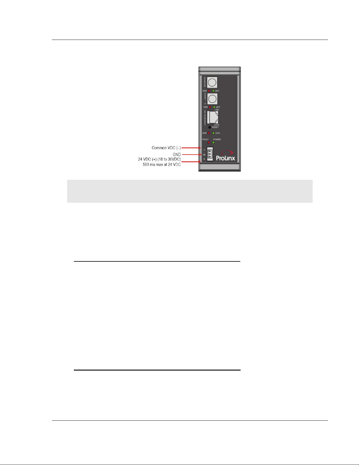
1.4 Connecting Power to the Unit
WARNING: Ensure that you do not reverse polarity when applying power to the module. This will
cause damage to the module’s power supply.
1.5 Install ProSoft Configuration Builder Software
You must install the ProSoft Configuration Builder (PCB) software in order to
configure the module. You can always get the newest version of ProSoft
Configuration Builder from the ProSoft Technology web site.
To install ProSoft Configuration Builder from the ProSoft Web Site
1 Open your web browser and navigate to http://www.prosoft-
technology.com/pcb
2 Click the D
Configuration Builder.
3 Choose "S
4 Save the file to your Windows Desktop, so that you can find it easily when
you have finished downloading.
5 When the download is complete, locate and open the file, and then follow the
instructions on your screen to install the program.
If you do not have access to the Internet, you can install ProSoft Configuration
Builder from the ProSoft Solutions CD-ROM, included in the package with your
module.
To install ProSoft Configuration Builder from the Product CD-ROM
1 Insert the ProSoft Solutions Product CD-ROM into the CD-ROM drive of your
PC. Wait for the startup screen to appear.
2 On the startup screen, click P
Windows Explorer file tree window.
OWNLOAD HERE link to download the latest version of ProSoft
AVE" or "SAVE FILE" when prompted.
RODUCT DOCUMENTATION. This action opens an
ProSoft Technology, Inc. Page 9 of 44
August 27, 2009
Page 10

DH485 ♦ ProLinx Gateway Start Here
DH485 Interface Driver Manual
3 Click to open the U
TILITIES folder. This folder contains all of the applications
and files you will need to set up and configure your module.
4 Double-click the S
"PCB_*.
EXE" file and follow the instructions on your screen to install the
ETUPCONFIGURATIONTOOL folder, double-click the
software on your PC. The information represented by the "*" character in the
file name is the PCB version number and, therefore, subject to change as
new versions of PCB are released.
Note: Many of the configuration and maintenance procedures use files and other utilities on the
CD-ROM. You may wish to copy the files from the Utilities folder on the CD-ROM to a convenient
location on your hard drive.
1.5.1 Using the Help System
Most of the information needed to help you use ProSoft Configuration Builder is
provided in a Help System that is always available whenever you are running
ProSoft Configuration Builder. The Help System does not require an Internet
connection.
To view the help pages, start ProSoft Configuration Builder, open the H
menu, and then choose CONTENTS.
ELP
Page 10 of 44 ProSoft Technology, Inc.
August 27, 2009
Page 11

Functional Overview DH485 ♦ ProLinx Gateway Driver Manual DH485 Interface
2 Functional Overview
In This Chapter
Master/Slave Serial Port........................................................................ 11
Module Internal Database .....................................................................11
Protocol Functional Specifications......................................................... 15
The DH-485 protocol driver is designed to accept DH-485 commands from an
attached DH-485 master unit (that is, SLC 5/03 processor ladder logic message
instruction). The DH-485 driver permits a remote master to interact with all data
contained in a module. The data can be derived from other DH-485 devices on
the network through a master port on a module. The driver actively issues DH485 commands to other nodes on the DH-485 network. One hundred userdefined commands are supported by the driver on each port.
2.1 Master/Slave Serial Port
Master mode issues read or write commands to other remote devices on the DH485 network. These commands are user-configured in the module via the master
command list received from the configuration file. Command status is returned to
the processor for each individual command in the command list status data area.
The location of this status block in a module’s internal database is user-defined.
The slave driver mode allows a module to respond to CIF and data read and
write commands issued by a remote node on the DH-485 network.
The Slave driver supports the following DH-485 command set:
Type Access Description
CIF Read 485CIF, Peer-to-Peer, Read MSG requests
CIF Write 485CIF, Peer-to-Peer, Write MSG requests
Data Table Read 500CPU, Peer-to-Peer, Read MSG requests
Data Table Write 500CPU, Peer-to-Peer, Write MSG requests
2.2 Module Internal Database
Central to the functionality of the module is the internal database. This database
is shared between all the ports on the module and is used as a conduit to pass
information from one device on one network to one or more devices on another
network. This permits data from devices on one communication port to be viewed
and controlled by devices on another port. In addition to data from the slave and
master ports, status and error information generated by the module can also be
mapped into the internal database.
ProSoft Technology, Inc. Page 11 of 44
August 27, 2009
Page 12
DH485 ♦ ProLinx Gateway Functional Overview
DH485 Interface Driver Manual
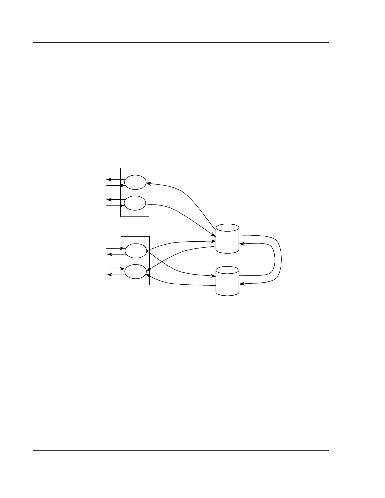
2.2.1 DH485 Serial Port Driver Access to Database
The module supports the common interface file (CIF) of the DH-485 protocol. A
separate data area can be defined for each application port. This data area is
divided into read and write data and is mapped into the module’s internal
database. The module’s application constantly transfers the read CIF data from
the CIF database to the module database and the write CIF data from the
module to the CIF database. The parameters used to define the CIF database
are contained in the configuration file. This optional feature of the module should
only be utilized if required by a remote master on the network. Otherwise, the
data file functions (500CPU message) instructions should be used to access and
control the module’s data. The following diagram shows the relationship of the
DH-485 drivers, the CIF database and the module’s database:
Request
Response
Request
Response
Request
Response
Request
Response
Master Driver
Slave Driver
Write
Function
Read
Function
Write
Function
Read
Function
Write Database
Read Database
Write Database
Read Database
Write CIF Request
Read CIF Request
Module
Database
CIF
Database
CIF Read Data
CIF Write Data
The Master driver uses the database in two ways:
1 A read command issued to a slave device by the master driver will return the
slave data into the internal database
2 A write command issued to a slave device by the master driver uses the data
in the internal database to write to the slave device. The slave driver
accesses data from the internal database. External DH-485 master devices
can monitor and control data in this database through the slave port. Setup of
the slave port only requires the CFG file.
Page 12 of 44 ProSoft Technology, Inc.
August 27, 2009
Page 13
Functional Overview DH485 ♦ ProLinx Gateway
Driver Manual DH485 Interface
The module supports the common interface file (CIF) of the DH-485 protocol. A
separate data area can be defined for each application port. This data area is
divided into read and write data and is mapped into the module’s internal
database. The module’s application constantly transfers the read CIF data from
the CIF database to the module database and the write CIF data from the
module to the CIF database. The parameters used to define the CIF database
are contained in the configuration file. This optional feature of the module should
only be utilized if required by a remote master on the network. Otherwise, the
data file functions (500CPU message) instructions should be used to access and
control the module’s data. The following diagram shows the relationship of the
DH-485 drivers, the CIF database and the module’s database:
Parameter Value Format
Read Register Start 600 Word
Read Register Count 600 Word
Write Register Start 0 Word
Write Register Count 600 Word
CIF Read DB Offset 1200 Byte
CIF Read Count 144 Byte
CIF Write DB Offset 0 Byte
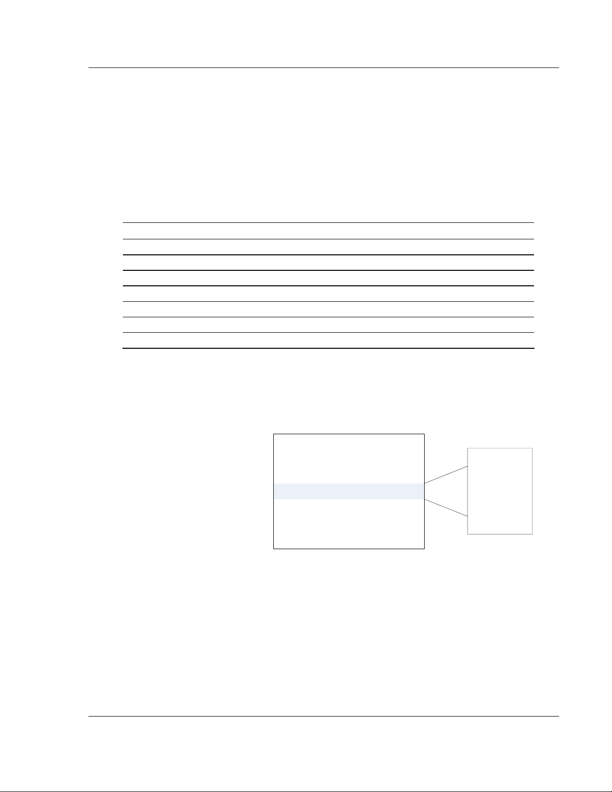
2.2.2 DH-485 CIF Information
The following illustration shows four different uses and configurations of the CIF
data area:
Example #1
CIF Read DB Offset:
CIF Read Count:
CIF Write DB Offset:
1000
244
-1
Read CIF Data Area
0 .
.
243
ProSoft Technology, Inc. Page 13 of 44
August 27, 2009
Page 14
DH485 ♦ ProLinx Gateway Functional Overview
DH485 Interface Driver Manual
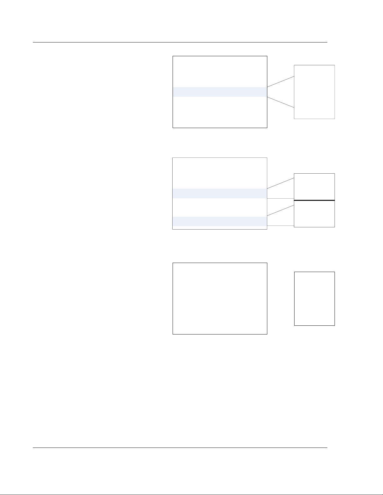
Example #2
0 .
CIF Read DB Offset:
CIF Read Count:
CIF Write DB Offset:
Example #3
CIF Read DB Offset:
CIF Read Count:
CIF Write DB Offset:
Example #4
-1
1000
1000
124
2000
Write CIF Data Area
0
.
243
0
Read CIF Data Area
123
124
Write CIF Data Area
243
0 .
CIF Read DB Offset:
CIF Read Count:
CIF Write DB Offset:
-1
-1
0
.
243
Example 1 only uses CIF read data and utilizes the maximum read data area.
Example 2 only uses the CIF write data and utilizes the maximum write data
area.
Example 3 uses both CIF read and write data. 124 bytes of read data are used
and 120 bytes of write data are used.
Example 4 does not use the CIF data in the application.
Page 14 of 44 ProSoft Technology, Inc.
August 27, 2009
Page 15

Functional Overview DH485 ♦ ProLinx Gateway
Driver Manual DH485 Interface
2.3 Protocol Functional Specifications
2.3.1 Functional Specifications - DH-485
The DH-485 protocol in its native form is a peer to peer token passing network.
The ProLinx DH-485 driver accesses the network functioning either as a Master
or as a Slave.
General Protocol Information
Error Checking BCC and CRC
Communication Parameters
DH-485 Slave Mode
In Slave mode, the module accepts commands from one or more Masters to
read/write data stored in the module’s internal data memory. In this mode, the
ProLinx unit is answering DH-485 commands and has the appearance of an SLC
processor to the network.
Local Station ID: 0 to 31
Port 0 Baud Rate: 110 to 38.4K baud
Port 1 Baud Rate: 110 to 19200 baud
Stop Bits: 1 or 2
Data Size: 7 or 8 bits
Parity: None, Even, Odd
RTS Timing delays: 0 to 65535 milliseconds
DH-485 Master Mode
In Master mode, the ProLinx DH-485 driver will actively gather data from other
devices on the network, controlling the read/write data transfer between the
gateway and other DH-485 devices, such as SLC processors. Data transfer can
be initiated and executed with the other devices without any ladder logic being
required in the Rockwell Automation slave hardware.
DH485 Functioning as a Master
Command List
Polling of command list
Up to 100 command per master port, each fully
configurable for function, slave address, register to/from
addressing and word/bit count
User configurable polling of commands, including
disabled, continuous and on change of data (write only)
2.3.2 General Specifications
ProLinx® Communication Gateways provide connectivity for two or more
dissimilar network types. The gateways, encased in sturdy extruded aluminum,
are stand-alone DIN-rail mounted solutions that provide data transfer between
many of today’s most widely used industrial automation protocols.
ProSoft Technology, Inc. Page 15 of 44
August 27, 2009
Page 16

DH485 ♦ ProLinx Gateway Functional Overview
DH485 Interface Driver Manual
2.3.3 Hardware Specifications
Specification Description
Power Supply
Current Load 500 mA max@ 32 VDC max
Operating Temperature -20 to 50°C (-4 to 122°F)
Storage Temperature -40 to 85°C (-40 to 185°F)
Relative Humidity 5% to 95% (non-condensing)
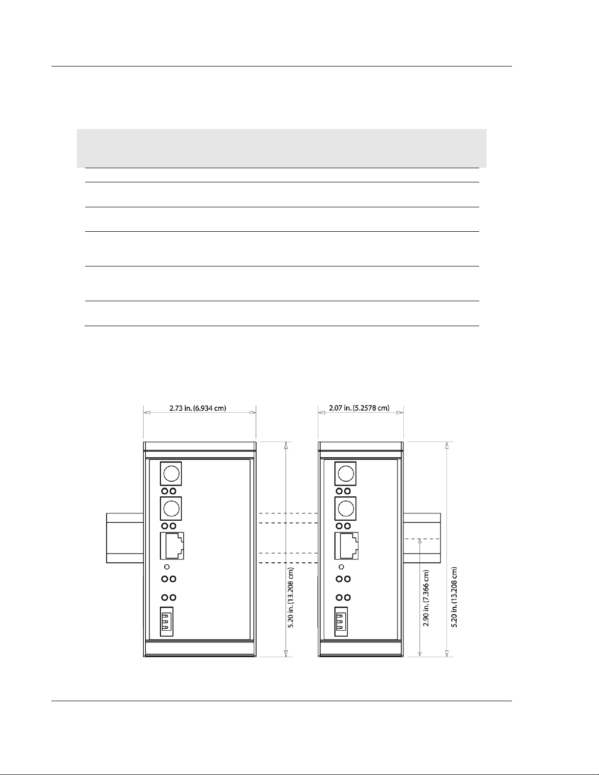
Dimensions
LED Indicators
Configuration
Serial Port
Ethernet Port
(Ethernet protocol gateways
only)
Application Serial Ports
Serial Port Isolation
Shipped with Each Unit
24 VDC nominal
18 to 32 VDC allowed
Positive, Negative, GND Terminals
2.5 mm screwdriver blade
Standard: 5.20 H x 2.07 W x 4.52 D inches
(13.2 cm H x 5.25 cm W x 11.48cm D)
Extended: 5.20 H x 2.73 W x 4.52 D inches
(13.2 cm H x 6.934 cm W x 11.48cm D)
Power and Module Status
Application Status
Serial Port Activity LED
Serial Activity and Error LED Status
DB-9M RS-232 only
No hardware handshaking
10Base-T half duplex RJ45 Connector
Link and Activity LED indicators
Electrical Isolation 1500 V rms at 50 Hz to 60 Hz for 60 s, applied as
specified in section 5.3.2 of IEC 60950: 1991
Ethernet Broadcast Storm Resiliency = less than or equal to 5000
[ARP] frames-per-second and less than or equal to 5 minutes
duration
RS-232/422/485
RS-232 handshaking configurable
RS-422/485 screw termination included
2500V RMS port signal isolation per UL 1577
3000V DC min. isolation port to ground and port to logic
Mini-DIN to DB-9M serial cables
4 ft RS-232 configuration cable
2.5mm screwdriver
CD (docs and Configuration utility)
RS-422/485 DB-9 to Screw Terminal Adaptor (1 or 4, depending on
ports)
Page 16 of 44 ProSoft Technology, Inc.
August 27, 2009
Page 17

Configure the Module DH485 ♦ ProLinx Gateway
Driver Manual DH485 Interface
3 Configure the Module
In This Chapter
Configuring Module Parameters............................................................19
Comment Entries................................................................................... 20
Printing a Configuration File ..................................................................20
[DH485 Port x].......................................................................................21
[DH485 Port x Commands]....................................................................24
[DH485 Port x Maps] .............................................................................27
Downloading a File from PC to the Module ...........................................28
To begin, start PROSOFT CONFIGURATION BUILDER (PCB).
ProSoft Technology, Inc. Page 17 of 44
August 27, 2009
Page 18

DH485 ♦ ProLinx Gateway Configure the Module
DH485 Interface Driver Manual
If you have used other Windows configuration tools before, you will find the
screen layout familiar. PCB’s window consists of a tree view on the left, and an
information pane and a configuration pane on the right side of the window. When
you first start PCB, the tree view consists of folders for D
EFAULT LOCATION, with a DEFAULT MODULE in the Default Location folder. The
D
EFAULT PROJECT and
following illustration shows the PCB window with a new project.
Page 18 of 44 ProSoft Technology, Inc.
August 27, 2009
Page 19

Configure the Module DH485 ♦ ProLinx Gateway
Driver Manual DH485 Interface
Your first task is to add the DH485 module to the project.
1 Use the mouse to select D
EFAULT MODULE in the tree view, and then click the
right mouse button to open a shortcut menu.
2 On the shortcut menu, choose C
HOOSE MODULE TYPE. This action opens the
CHOOSE MODULE TYPE dialog box.
3 In the P
RODUCT LINE FILTER area of the dialog box, select the ProLinx Series
(4000, 5000, or 6000) for your gateway.
4 In the S
click OK
ELECT MODULE TYPE dropdown list, select your gateway, and then
to save your settings and return to the ProSoft Configuration Builder
window.
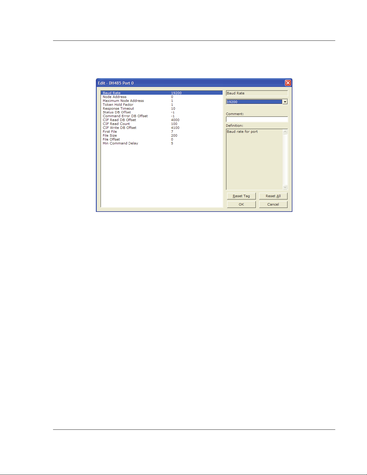
3.1 Configuring Module Parameters
1 Click on the plus sign next to the icon to expand module information.
2 Double-click the
3 To edit a parameter, select the parameter in the left pane and make your
changes in the right pane.
4 Click OK
to save your changes.
ProSoft Technology, Inc. Page 19 of 44
August 27, 2009
icon to open the EDIT dialog box.
Page 20

DH485 ♦ ProLinx Gateway Configure the Module
DH485 Interface Driver Manual
3.2 Comment Entries
1 Click the plus sign to the left of the icon to expand the module
Comments.
2 Double-click the
appears.
icon. The EDIT - MODULE COMMENT dialog
3 Enter your comment and click OK to save your changes.
3.3 Printing a Configuration File
1 Select the MODULE icon, and then click the right mouse button to open a
shortcut menu.
2 On the shortcut menu, choose V
IEW CONFIGURATION window.
V
3 On the V
P
RINT. This action opens the PRINT dialog box.
4 On the P
select printing options, and then click OK.
IEW CONFIGURATION window, open the FILE menu, and choose
RINT dialog box, choose the printer to use from the dropdown list,
IEW CONFIGURATION. This action opens the
Page 20 of 44 ProSoft Technology, Inc.
August 27, 2009
Page 21
Configure the Module DH485 ♦ ProLinx Gateway
Driver Manual DH485 Interface
3.4 [DH485 Port x]
General configuration information for the specified DH-485 port on the module
3.4.1 Baud Rate
Range 1200 to 19200
This is the baud rate to use for the DH485 network. Select one of the listed baud
rates.
3.4.2 Node Address
Range 0 to 31
This is the node address to be utilized by the DH-485 driver for this port on the
network. Enter a value not already used on the network in the range of 0 to 31. If
a value of 255 is utilized or set by the module, the port is disabled. Note: All
nodes on the network should be set to the lowest set of values in the range of 1
to 4).
3.4.3 Maximum Node Address
Range 0 to 31
Enter the maximum address that the initiator searches for before wrapping to
zero. The default is 31. This parameter should be set to the maximum node
address set in the DH-485 network.
ProSoft Technology, Inc. Page 21 of 44
August 27, 2009
Page 22

DH485 ♦ ProLinx Gateway Configure the Module
DH485 Interface Driver Manual
3.4.4 Token Hold Factor
Range 0 to 31
Enter the number of transmissions (plus retries) that a node holding a token can
send onto the data link each time that it receives the token. Enter a value
between 0 and 31. The default is 1.
3.4.5 Response Timeout
Range 1 to 50
This parameter sets the number of 100 millisecond time intervals to wait for a
response to a request from the module. If the module does not receive the
response with in the time period specified, a timeout condition will be set for the
command.
3.4.6 Status DB Offset
Range -1 to 3980
This parameter sets the location of the status data for the port in the module’s
internal database. If the parameter is set to -1, the data is not placed in the
database. If a valid value is entered, the module’s status data will be placed in
the database starting at the location indicated.
3.4.7 Command Error DB Offset
Range -1 to 3900
This parameter sets the location of the command error list data for the port in the
module's internal database. If the parameter is set to -1, the data is not placed in
the database. If a valid value is entered, the module's error list data will be placed
in the database starting at the location indicated.
3.4.8 CIF Read DB Offset
Range -1 to 7500 (Only even values)
This parameter sets the starting byte location in the module's database where the
CIF file Read will be placed. This data is passed from CIF memory area to the
set location in the module's database. If this parameter is set to -1, no CIF read
data will be utilized. When the CIF Read Area is disabled (CIF Read DB Offset =
-1) or CIF Read Count = 0, the Debug menu shows this parameter as 65535.
3.4.9 CIF Read Count
Range 0 to 242
This parameters sets the number of bytes to transfer from the CIF file to the
database. The CIF write count will be calculated as (244 - CIF Read Count)
Page 22 of 44 ProSoft Technology, Inc.
August 27, 2009
Page 23

Configure the Module DH485 ♦ ProLinx Gateway
Driver Manual DH485 Interface
3.4.10 CIF Write DB Offset
Range -1 to 7500 (Only even values)
This parameter sets the starting byte location in the module's database where the
CIF file Write data will be read from. This data is passed to the CIF memory area
from the set location in the module's database. If this parameter is set to -1, no
CIF write data will be utilized. When the CIF Write Area is disabled (CIF Write DB
Offset = -1) or CIF Write Count = 0, the Debug menu shows this parameter as
65535.
3.4.11 First File
Range 0 to 255
This parameter sets the file number for the first file to be emulated by the
module.
3.4.12 File Size
Range 1 to 1000
This parameter sets the word size of all the files emulated in the module
3.4.13 File Offset
Range 1 to 999
This parameter sets the word offset into the module’s database where the file
emulation will start.
3.4.14 Min Command Delay
Range 0 to 10000
This parameter sets the minimum number of milliseconds to wait before issuing
each command. This parameter is utilized to keep the network from being
flooded with requests from the module.
ProSoft Technology, Inc. Page 23 of 44
August 27, 2009
Page 24

DH485 ♦ ProLinx Gateway Configure the Module
DH485 Interface Driver Manual
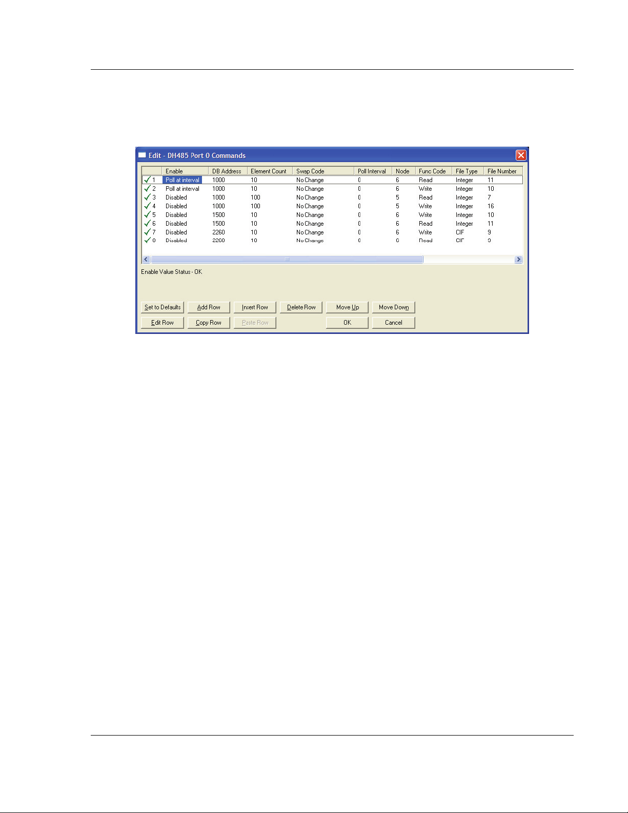
3.5 [DH485 Port x Commands]
The [DH485 Port x Commands] section for each port defines the commands to
be issued by the module to other devices on the network. These commands can
be used for data collection and/or control.
3.5.1 Command List Overview
In order to interface the DH485 module to act as a master device, you must
construct a command list for each port. The commands in the list specify the
node to be addressed, the function to be performed (read or write), the data area
in the device to interface with and the registers in the internal database to be
associated with the device data. The command list supports up to 100
commands. The command list is processed from top (command #0) to bottom. A
poll interval parameter is associated with each command to specify a minimum
delay time in seconds between the issuance of a command. If the user specifies
a value of 10 for the parameter, the command will be executed no more
frequently than every 10 seconds.
Write commands have a special feature, as they can be set to execute only if the
data in the write command changes. If the register data values in the command
have not changed since the command was last issued, the command will not be
executed. If the data in the command has changed since the command was last
issued, the command will be executed. Use of this feature can lighten the load on
the network. In order to implement this feature; set the enable code for the
command to a value of 2.
Page 24 of 44 ProSoft Technology, Inc.
August 27, 2009
Page 25
Configure the Module DH485 ♦ ProLinx Gateway
Driver Manual DH485 Interface
3.5.2 Command Entry Format
Each command entered in the command list section has the same format. The
following is an example section for Port 0:
The first part of each record in the section relates to the module interface and the
last part relates to the node to be interfaced with. The following topics describe
each field required for a user command
3.5.3 Enable Type Code
This field defines if the command is enabled and when it should be executed.
The following codes are recognized by the application:
0 = Command is disabled
1 = Command is executed at the polling interval specified
2 = The write command is only executed when data changes
3.5.4 Database Start Address
This field defines the starting address in the module’s internal database to
associate with the command. This field can have a value from 0 to 3999. The
address supplied is a word address in the database.
3.5.5 Element Count
This field defines the number of elements to be used with the command. If the
command is interfacing with CIF data, this parameter represents a byte count.
For data file access, the data size utilized depends on the file type used.
ProSoft Technology, Inc. Page 25 of 44
August 27, 2009
Page 26

DH485 ♦ ProLinx Gateway Configure the Module
DH485 Interface Driver Manual
3.5.6 Swap Code
This field changes the order of the bytes and/or words used when sending or
receiving the data. The following codes are utilized:
Swap Code Description
0 None - No Change is made in the byte ordering (1234 = 1234)
1 Words - The words are swapped (1234=3412)
2
3 Bytes - The bytes in each word are swapped (1234=2143)
Words & Bytes - The words are swapped then the bytes in each word are
swapped (1234=4321)
3.5.7 Poll Interval
This field sets the time interval between successive execution of the command.
This parameter is specified in seconds. If the field is set to 10, the command will
not be executed more frequently than every 10 seconds.
3.5.8 Node Number
This field defines the node address of the DH-485 node to send the command
request. This field should be set to a value from 0 to 31.
3.5.9 Function Code
This field defines the function to be executed by the command. The module uses
the following codes:
0 = Read
1 = Write
3.5.10 File Type
This field defines the file type to be interfaced with in the other DH-485 node. The
program utilizes the following codes for this field:
0 = Status File (2 bytes per element)
1 = Bit File (2 bytes per element)
2 = Timer File (6 bytes per element)
3 = Counter File (6 bytes per element)
4 = Control File (6 bytes per element)
5 = Integer File (2 bytes per element)
6 = Floating-point File (4 bytes per element)
10 = CIF File (1 byte per element)
3.5.11 File Number
This field defines the file number to access. This field is ignored for CIF file
access and should be set to 0. For Bit, Timer, Counter, Control, Integer, and
Float data types, a maximum value of 255 is valid.
Page 26 of 44 ProSoft Technology, Inc.
August 27, 2009
Page 27

Configure the Module DH485 ♦ ProLinx Gateway
Driver Manual DH485 Interface
3.5.12 Element Number
This field defines the first element in the file specified to be associated with the
command. For a CIF file, this parameter is given as the byte location. For Bit,
Timer, Counter, Control, Integer, and Float data types, the maximum value is
255. For CIF data types the maximum value is 510.
Maximum Element Counts for Read/Write Commands
The maximum number of elements requested from a remote node is determined
by the file type and function code utilized in the command. The following table
lists the maximum element count for each file type:
File Type Bytes/Elements Read Result Write Result
Status 2 83 83
Bit 2 118 115
Timer 6 39 38
Counter 6 39 38
Control 6 39 38
Integer 2 118 115
Float 4 59 57
CIF 1 236 234
3.6 [DH485 Port x Maps]
Note: This section applies only when the DH485 module is operating in Slave mode.
Each file map entered in the configuration file has the same format. The following
is an example section for Port 0:
These file maps are searched first when a node on the network makes a request.
If the requested data area is found in the map list, the database area associated
ProSoft Technology, Inc. Page 27 of 44
August 27, 2009
Page 28

DH485 ♦ ProLinx Gateway Configure the Module
DH485 Interface Driver Manual
with the command will be used. If the requested data area is not found in the
map list, the fixed mapping data configuration will be used.
The following topics describe each field required for an override map.
3.6.1 DB Address
This field defines the starting address in the module's database for the file
emulation. This parameter can be assigned a value of 0 to 3999.
3.6.2 File Number
This field defines the file number to be emulated at the specified database
location.
3.6.3 Element
This field specifies the first element in the file to be emulated. This element
number corresponds to the database start address set for the record.
3.6.4 Word Count (Length)
This field defines the number of word registers to be emulated in the file.
3.7 Downloading a File from PC to the Module
1 Verify that your PC is connected to the gateway with a null-modem serial
cable connected to the serial port on your PC and the serial port on the
gateway
2 Open the P
3 On the M
scans for communication ports on your PC. When the scan is complete, the
D
OWNLOAD dialog box opens.
ROJECT menu, and then choose MODULE.
ODULE menu, choose DOWNLOAD. Wait while ProSoft Configuration
4 Select the port to use for the download.
5 Click the D
OWNLOAD button.
Page 28 of 44 ProSoft Technology, Inc.
August 27, 2009
Page 29

Serial Port Protocol Error/Status Data DH485 ♦ ProLinx Gateway
Driver Manual DH485 Interface
4 Serial Port Protocol Error/Status Data
In This Chapter
Viewing Error and Status Data ..............................................................29
DH485 Error and Status Data Area Addresses .....................................29
The second and most thorough troubleshooting method for debugging the
operation of the DH-485 driver (and the module in general), is the powerful
Debug port on the module which provides much more complete access to the
internal operation and status of the module. Accessing the Debug capabilities of
the module is accomplished easily by connecting a PC to the Debug port and
loading a terminal program such as ProSoft Configuration Builder or
Hyperterminal.
4.1 Viewing Error and Status Data
The following topics describe the register addresses that contain protocol error
and status data. Viewing the contents of each register is accomplished using the
Database View option. The use of this option and its associated features are
described in detail in the ProLinx Reference Guide.
4.2 DH485 Error and Status Data Area Addresses
DH485 Status Data Area
Byte # Description
0 to 3 Active node bits for stations 0 to 31
4 to 5 Online status (0=Offline, 1=Online)
6 to 7 Node address of the unit/port emulated
8 to 9 Current command index being issued
10 to 11 Total number of request messages
12 to 13 Total number of response messages received
14 to 15 Total number of command list errors
16 to 17 Configuration error word. Each bit represent a configuration error condition.
18 to 19 Reserved for future use.
20 to 21 Total number of packets received
22 to 23 Total number of packets transmitted
24 Total retry count
25 Retry failure counter
26 Total number of NAK’s because of no memory for reception
ProSoft Technology, Inc. Page 29 of 44
August 27, 2009
Page 30

DH485 ♦ ProLinx Gateway Serial Port Protocol Error/Status Data
DH485 Interface Driver Manual
Byte # Description
27 Total number of NAK’s because of no memory for transmission
28 Total number of bad packets
29 Total number of bad control packets
30 Total number of packets received with a bad CRC value
31 Total number of parity errors
32 Total number of framing errors
33 Total number of overrun errors
34 Total number of unexpected bytes received
35 Total number of bad LSAP’s received
Word# Description
0 Error code for command index 0.
1 Error code for command index 1.
--- --99 Error code for command index 99.
4.2.1 DH485 General Error Codes
Error # Description
0 Operation successful
1 Invalid parameter
2 Device is already open
3 Device is not present
4 Invalid access
5 The function has timed out
6
7 Unable to configure the requested port
8 Unable to allocate memory for DH-485 driver
4.2.2 DH485 API Specific Error Codes
Error # Description
0x0800 Command only permitted in master mode
0x0801 Command already active on the port
0x0802 Response to request timed out
0x0803 Unable to allocate memory for the request
0x0804 Illegal command or format
0x0805 Host could not complete request (hardware fault)
0x0806 Out of memory, file or rung does not exist
0x0807 Field has an illegal value
0x0808 Not enough fields in request message
Page 30 of 44 ProSoft Technology, Inc.
August 27, 2009
Page 31

Serial Port Protocol Error/Status Data DH485 ♦ ProLinx Gateway
Driver Manual DH485 Interface
Error # Description
0x0809 Too many fields in request message
0x080A Symbol not found
0x080B Symbol 0 or greater than maximum characters permitted in message
0x080C Does not exist, illegal size
0x080D File wrong size, address past end of file
0x080E Data or file too large (memory not available)
0x080F Request too large to transmit message (size+address > max message)
0x0810 Access denied
0x0811 Command cannot be executed
0x0812 Illegal data type information
0x0813 Illegal parameter, invalid data in search or command block
0x0814 File open by another node
0x0815 Program owned by another node
0x0816 Unknown error returned from host
0x0817 No message active on the port
4.2.3 DH485 Configuration Error Word
Bit Code Description
0 0x0001 Invalid baud rate
1 0x0002 Invalid node address
2 0x0004 Invalid maximum node address
3 0x0008 Invalid token hold factor
4 0x0010 Invalid response timeout
5 0x0020 Invalid status or command error DB offset
6 0x0040 Invalid CIF read count or DB offset
7 0x0080 Invalid CIF write DB offset
8 0x0100 Invalid file size
9 0x0200 Invalid file offset
10 0x0400
11 0x0800
12 0x1000
13 0x2000
14 0x4000
15 0x8000
ProSoft Technology, Inc. Page 31 of 44
August 27, 2009
Page 32

DH485 ♦ ProLinx Gateway Serial Port Protocol Error/Status Data
DH485 Interface Driver Manual
Page 32 of 44 ProSoft Technology, Inc.
August 27, 2009
Page 33

Reference DH485 ♦ ProLinx Gateway
Driver Manual DH485 Interface
5 Reference
In This Chapter
Status Data Area ................................................................................... 33
Command Error List Data Area .............................................................34
RS-232 ..................................................................................................34
RS-485 ..................................................................................................34
5.1 Status Data Area
Offset Description
14100 Active node bits for stations 0 to 15
14101 Active node bits for stations 16 to 31
14102 Online status (0=Offline, 1=Online)
14103 Node address of the unit/port emulated
14104 Current command index being issued
14105 Total number of request messages
14106 Total number of response messages received
14107 Total number of command list errors
14108 Configuration error word. Each bit represent a configuration error condition.
14109 Reserved for future use.
14110 Total number of packets received
14111 Total number of packets transmitted
14112(1) Total retry count
14112(2) Retry failure counter
14113(1) Total number of NAK’s because of no memory for reception
14113(2) Total number of NAK’s because of no memory for transmission
14114(1) Total number of bad packets
14114(2) Total number of bad control packets
14115(1) Total number of packets received with a bad CRC value
14115(2) Total number of parity errors
14116(1) Total number of framing errors
14116(2) Total number of overrun errors
14117(1) Total number of unexpected bytes received
14117(2) Total number of bad LSAP’s received
(1) = First byte of the word
(2) = Second byte of the word
ProSoft Technology, Inc. Page 33 of 44
August 27, 2009
Page 34

DH485 ♦ ProLinx Gateway Reference
DH485 Interface Driver Manual
5.2 Command Error List Data Area
Word# Description
14200 Error code for command index 0.
14201 Error code for command index 1.
... ...
14299 Error code for command index 99.
5.3 RS-232
When the RS-232 interface is selected, you must use an AIC+ to connect the
port to a DH485. The cable required for this connection is shown in the following
illustration:
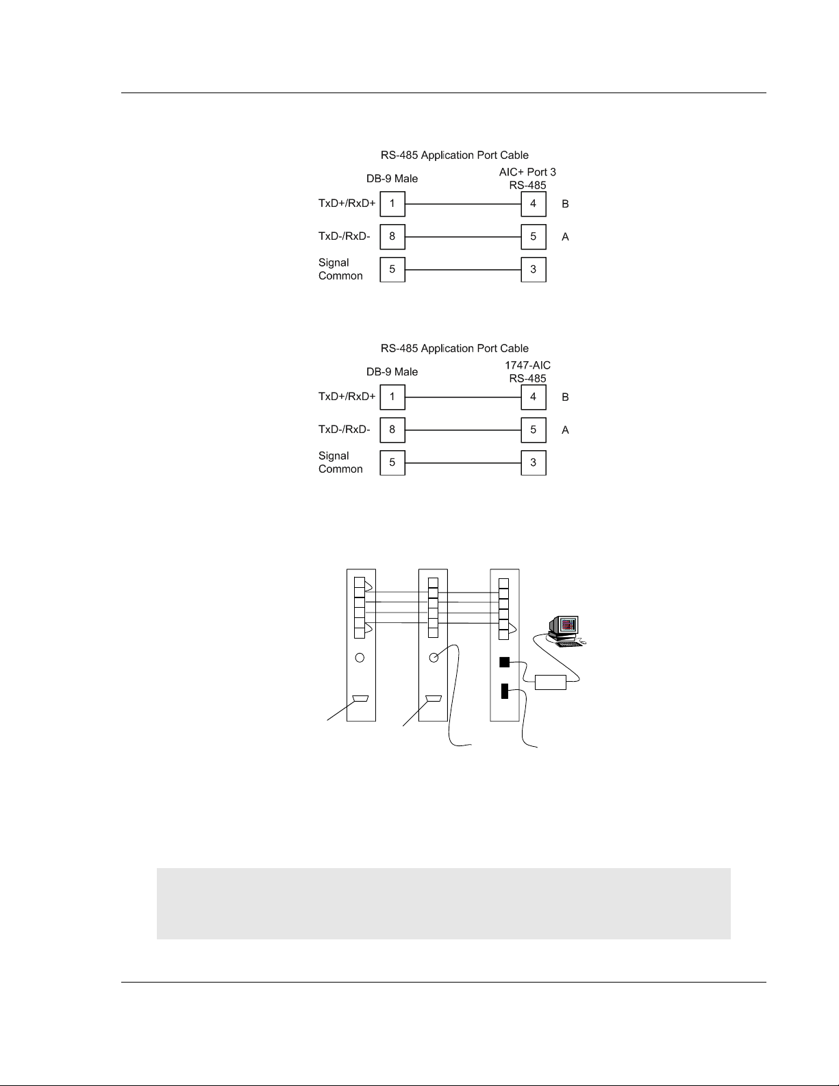
5.4 RS-485
The RS-485 uses a single two or three wire cable. The use of the ground is
optional and dependent on the RS-485 network. The cable required for this
interface is shown in the following diagram:
Page 34 of 44 ProSoft Technology, Inc.
August 27, 2009
Page 35
Reference DH485 ♦ ProLinx Gateway
Driver Manual DH485 Interface
When connecting to port 3 of an AIC+ module, the following is the correct wiring:
When connecting to a 1747-AIC module, the following is the correct wiring:
The following illustration shows an example DH-485 network.
DH485
Port RS-485
DB-9 Male
To
RS-232
AIC+
1747 - AIC
1
2
3
4
5
6
To
MicroLogix
1000
1
2
3
4
5
6
Workstation
1747-PIC
To SLC 5/03
Channel 1
Chassis Gnd
Shield
Common
B
A
Termination
Port 2
Port 1
To
ProSoft DH485
RS-232
AIC+
1
2
3
4
5
6
ProSoft DH485
This network displays the two different methods to configure the module for a
DH-485 network. Please note there is no place on the module’s RS-485 to land
the shield, and when used in the configuration shown, it must be wired externally.
Verify that the RS interface jumper on the module is set to the correct position:
RS-232 or RS-485.
Note: Terminating resistors are generally not required on the RS-485 network, unless you are
experiencing communication problems that can be attributed to signal echoes or reflections. In this
case, install a 120 ohm terminating resistor on the RS-485 line.
ProSoft Technology, Inc. Page 35 of 44
August 27, 2009
Page 36

DH485 ♦ ProLinx Gateway Reference
DH485 Interface Driver Manual
Page 36 of 44 ProSoft Technology, Inc.
August 27, 2009
Page 37

Support, Service & Warranty DH485 ♦ ProLinx Gateway
Driver Manual DH485 Interface
6 Support, Service & Warranty
In This Chapter
How to Contact Us: Technical Support.................................................. 37
Return Material Authorization (RMA) Policies and Conditions...............38
LIMITED WARRANTY........................................................................... 39
ProSoft Technology, Inc. (ProSoft) is committed to providing the most efficient
and effective support possible. Before calling, please gather the following
information to assist in expediting this process:
1 Product Version Number
2 System architecture
3 Network details
If the issue is hardware related, we will also need information regarding:
1 Module configuration and contents of file
o Module Operation
o Configuration/Debug status information
o LED patterns
2 Information about the processor and user data files as viewed through and
LED patterns on the processor.
3 Details about the serial devices interfaced, if any.
6.1 How to Contact Us: Technical Support
Internet
Asia Pacific
+603.7724.2080, support.asia@prosoft-technology.com
Languages spoken include: Chinese, English
Europe (location in Toulouse, France)
+33 (0) 5.34.36.87.20, support.EMEA@prosoft-technology.com
Languages spoken include: French, English
North America/Latin America (excluding Brasil) (location in California)
+1.661.716.5100, support@prosoft-technology.com
Languages spoken include: English, Spanish
For technical support calls within the United States, an after-hours answering system allows pager
access to one of our qualified technical and/or application support engineers at any time to answer
your questions.
Brasil (location in Sao Paulo)
+55-11-5084-5178, eduardo@prosoft-technology.com
Languages spoken include: Portuguese, English
Web Site: www.prosoft-technology.com/support
E-mail address: support@prosoft-technology.com
ProSoft Technology, Inc. Page 37 of 44
August 27, 2009
Page 38

DH485 ♦ ProLinx Gateway Support, Service & Warranty
DH485 Interface Driver Manual
6.2 Return Material Authorization (RMA) Policies and Conditions
The following RMA Policies and Conditions (collectively, "RMA Policies") apply to
any returned Product. These RMA Policies are subject to change by ProSoft
without notice. For warranty information, see "Limited Warranty". In the event of
any inconsistency between the RMA Policies and the Warranty, the Warranty
shall govern.
6.2.1 All Product Returns:
a) In order to return a Product for repair, exchange or otherwise, the
Customer must obtain a Returned Material Authorization (RMA) number
from ProSoft and comply with ProSoft shipping instructions.
b) In the event that the Customer experiences a problem with the Product for
any reason, Customer should contact ProSoft Technical Support at one of
the telephone numbers listed above (page
Engineer will request that you perform several tests in an attempt to
isolate the problem. If after completing these tests, the Product is found to
be the source of the problem, we will issue an RMA.
c) All returned Products must be shipped freight prepaid, in the original
shipping container or equivalent, to the location specified by ProSoft, and
be accompanied by proof of purchase and receipt date. The RMA number
is to be prominently marked on the outside of the shipping box. Customer
agrees to insure the Product or assume the risk of loss or damage in
transit. Products shipped to ProSoft using a shipment method other than
that specified by ProSoft or shipped without an RMA number will be
returned to the Customer, freight collect. Contact ProSoft Technical
Support for further information.
d) A 10% restocking fee applies to all warranty credit returns whereby a
Customer has an application change, ordered too many, does not need,
and so on.
37). A Technical Support
6.2.2 Procedures for Return of Units Under Warranty:
A Technical Support Engineer must approve the return of Product under
ProSoft’s Warranty:
a) A replacement module will be shipped and invoiced. A purchase order will
be required.
b) Credit for a product under warranty will be issued upon receipt of
authorized product by ProSoft at designated location referenced on the
Return Material Authorization.
6.2.3 Procedures for Return of Units Out of Warranty:
a) Customer sends unit in for evaluation
b) If no defect is found, Customer will be charged the equivalent of $100
USD, plus freight charges, duties and taxes as applicable. A new
purchase order will be required.
Page 38 of 44 ProSoft Technology, Inc.
August 27, 2009
Page 39

Support, Service & Warranty DH485 ♦ ProLinx Gateway
Driver Manual DH485 Interface
c) If unit is repaired, charge to Customer will be 30% of current list price
(USD) plus freight charges, duties and taxes as applicable. A new
purchase order will be required or authorization to use the purchase order
submitted for evaluation fee.
The following is a list of non-repairable units:
o 3150 - All
o 3750
o 3600 - All
o 3700
o 3170 - All
o 3250
o 1560 - Can be repaired, only if defect is the power supply
o 1550 - Can be repaired, only if defect is the power supply
o 3350
o 3300
o 1500 - All
6.3 LIMITED WARRANTY
This Limited Warranty ("Warranty") governs all sales of hardware, software and
other products (collectively, "Product") manufactured and/or offered for sale by
ProSoft, and all related services provided by ProSoft, including maintenance,
repair, warranty exchange, and service programs (collectively, "Services"). By
purchasing or using the Product or Services, the individual or entity purchasing or
using the Product or Services ("Customer") agrees to all of the terms and
provisions (collectively, the "Terms") of this Limited Warranty. All sales of
software or other intellectual property are, in addition, subject to any license
agreement accompanying such software or other intellectual property.
6.3.1 What Is Covered By This Warranty
a) Warranty On New Products: ProSoft warrants, to the original purchaser,
that the Product that is the subject of the sale will (1) conform to and
perform in accordance with published specifications prepared, approved
and issued by ProSoft, and (2) will be free from defects in material or
workmanship; provided these warranties only cover Product that is sold as
new. This Warranty expires three years from the date of shipment (the
"Warranty Period"). If the Customer discovers within the Warranty Period
a failure of the Product to conform to specifications, or a defect in material
or workmanship of the Product, the Customer must promptly notify
ProSoft by fax, email or telephone. In no event may that notification be
received by ProSoft later than 39 months. Within a reasonable time after
notification, ProSoft will correct any failure of the Product to conform to
specifications or any defect in material or workmanship of the Product,
with either new or used replacement parts. Such repair, including both
parts and labor, will be performed at ProSoft’s expense. All warranty
service will be performed at service centers designated by ProSoft.
ProSoft Technology, Inc. Page 39 of 44
August 27, 2009
Page 40

DH485 ♦ ProLinx Gateway Support, Service & Warranty
DH485 Interface Driver Manual
b) Warranty On Services: Materials and labor performed by ProSoft to repair
a verified malfunction or defect are warranteed in the terms specified
above for new Product, provided said warranty will be for the period
remaining on the original new equipment warranty or, if the original
warranty is no longer in effect, for a period of 90 days from the date of
repair.
6.3.2 What Is Not Covered By This Warranty
a) ProSoft makes no representation or warranty, expressed or implied, that
the operation of software purchased from ProSoft will be uninterrupted or
error free or that the functions contained in the software will meet or
satisfy the purchaser’s intended use or requirements; the Customer
assumes complete responsibility for decisions made or actions taken
based on information obtained using ProSoft software.
b) This Warranty does not cover the failure of the Product to perform
specified functions, or any other non-conformance, defects, losses or
damages caused by or attributable to any of the following: (i) shipping; (ii)
improper installation or other failure of Customer to adhere to ProSoft’s
specifications or instructions; (iii) unauthorized repair or maintenance; (iv)
attachments, equipment, options, parts, software, or user-created
programming (including, but not limited to, programs developed with any
IEC 61131-3, "C" or any variant of "C" programming languages) not
furnished by ProSoft; (v) use of the Product for purposes other than those
for which it was designed; (vi) any other abuse, misapplication, neglect or
misuse by the Customer; (vii) accident, improper testing or causes
external to the Product such as, but not limited to, exposure to extremes
of temperature or humidity, power failure or power surges; or (viii)
disasters such as fire, flood, earthquake, wind and lightning.
c) The information in this Agreement is subject to change without notice.
ProSoft shall not be liable for technical or editorial errors or omissions
made herein; nor for incidental or consequential damages resulting from
the furnishing, performance or use of this material. The user guide
included with your original product purchase from ProSoft contains
information protected by copyright. No part of the guide may be duplicated
or reproduced in any form without prior written consent from ProSoft.
6.3.3 Disclaimer Regarding High Risk Activities
Product manufactured or supplied by ProSoft is not fault tolerant and is not
designed, manufactured or intended for use in hazardous environments requiring
fail-safe performance including and without limitation: the operation of nuclear
facilities, aircraft navigation of communication systems, air traffic control, direct
life support machines or weapons systems in which the failure of the product
could lead directly or indirectly to death, personal injury or severe physical or
environmental damage (collectively, "high risk activities"). ProSoft specifically
disclaims any express or implied warranty of fitness for high risk activities.
Page 40 of 44 ProSoft Technology, Inc.
August 27, 2009
Page 41

Support, Service & Warranty DH485 ♦ ProLinx Gateway
Driver Manual DH485 Interface
6.3.4 Intellectual Property Indemnity
Buyer shall indemnify and hold harmless ProSoft and its employees from and
against all liabilities, losses, claims, costs and expenses (including attorney’s
fees and expenses) related to any claim, investigation, litigation or proceeding
(whether or not ProSoft is a party) which arises or is alleged to arise from Buyer’s
acts or omissions under these Terms or in any way with respect to the Products.
Without limiting the foregoing, Buyer (at its own expense) shall indemnify and
hold harmless ProSoft and defend or settle any action brought against such
Companies to the extent based on a claim that any Product made to Buyer
specifications infringed intellectual property rights of another party. ProSoft
makes no warranty that the product is or will be delivered free of any person’s
claiming of patent, trademark, or similar infringement. The Buyer assumes all
risks (including the risk of suit) that the product or any use of the product will
infringe existing or subsequently issued patents, trademarks, or copyrights.
a) Any documentation included with Product purchased from ProSoft is
protected by copyright and may not be duplicated or reproduced in any
form without prior written consent from ProSoft.
b) ProSoft’s technical specifications and documentation that are included
with the Product are subject to editing and modification without notice.
c) Transfer of title shall not operate to convey to Customer any right to make,
or have made, any Product supplied by ProSoft.
d) Customer is granted no right or license to use any software or other
intellectual property in any manner or for any purpose not expressly
permitted by any license agreement accompanying such software or other
intellectual property.
e) Customer agrees that it shall not, and shall not authorize others to, copy
software provided by ProSoft (except as expressly permitted in any
license agreement accompanying such software); transfer software to a
third party separately from the Product; modify, alter, translate, decode,
decompile, disassemble, reverse-engineer or otherwise attempt to derive
the source code of the software or create derivative works based on the
software; export the software or underlying technology in contravention of
applicable US and international export laws and regulations; or use the
software other than as authorized in connection with use of Product.
f) Additional Restrictions Relating To Software And Other Intellectual
Property
In addition to compliance with the Terms of this Warranty, Customers
purchasing software or other intellectual property shall comply with any
license agreement accompanying such software or other intellectual
property. Failure to do so may void this Warranty with respect to such
software and/or other intellectual property.
6.3.5 Disclaimer of all Other Warranties
The Warranty set forth in What Is Covered By This Warranty (page 39) are in lieu
of all other warranties, express or implied, including but not limited to the implied
warranties of merchantability and fitness for a particular purpose.
ProSoft Technology, Inc. Page 41 of 44
August 27, 2009
Page 42

DH485 ♦ ProLinx Gateway Support, Service & Warranty
DH485 Interface Driver Manual
6.3.6 Limitation of Remedies **
In no event will ProSoft or its Dealer be liable for any special, incidental or
consequential damages based on breach of warranty, breach of contract,
negligence, strict tort or any other legal theory. Damages that ProSoft or its
Dealer will not be responsible for included, but are not limited to: Loss of profits;
loss of savings or revenue; loss of use of the product or any associated
equipment; loss of data; cost of capital; cost of any substitute equipment,
facilities, or services; downtime; the claims of third parties including, customers of
the Purchaser; and, injury to property.
** Some areas do not allow time limitations on an implied warranty, or allow the exclusion or
limitation of incidental or consequential damages. In such areas, the above limitations may not
apply. This Warranty gives you specific legal rights, and you may also have other rights which vary
from place to place.
6.3.7 Time Limit for Bringing Suit
Any action for breach of warranty must be commenced within 39 months
following shipment of the Product.
6.3.8 No Other Warranties
Unless modified in writing and signed by both parties, this Warranty is
understood to be the complete and exclusive agreement between the parties,
suspending all oral or written prior agreements and all other communications
between the parties relating to the subject matter of this Warranty, including
statements made by salesperson. No employee of ProSoft or any other party is
authorized to make any warranty in addition to those made in this Warranty. The
Customer is warned, therefore, to check this Warranty carefully to see that it
correctly reflects those terms that are important to the Customer.
6.3.9 Allocation of Risks
This Warranty allocates the risk of product failure between ProSoft and the
Customer. This allocation is recognized by both parties and is reflected in the
price of the goods. The Customer acknowledges that it has read this Warranty,
understands it, and is bound by its Terms.
6.3.10 Controlling Law and Severability
This Warranty shall be governed by and construed in accordance with the laws of
the United States and the domestic laws of the State of California, without
reference to its conflicts of law provisions. If for any reason a court of competent
jurisdiction finds any provisions of this Warranty, or a portion thereof, to be
unenforceable, that provision shall be enforced to the maximum extent
permissible and the remainder of this Warranty shall remain in full force and
effect. Any cause of action with respect to the Product or Services must be
instituted in a court of competent jurisdiction in the State of California.
Page 42 of 44 ProSoft Technology, Inc.
August 27, 2009
Page 43

Index DH485 ♦ ProLinx Gateway
Driver Manual DH485 Interface
File Type • 26
First File • 23
Function Code • 26
Index
Functional Overview • 11
Functional Specifications - DH-485 • 15
G
[
[DH485 Port x Commands] • 24
[DH485 Port x Maps] • 27
[DH485 Port x] • 21
A
All Product Returns: • 38
All ProLinx® Products • 2
Allocation of Risks • 42
B
Baud Rate • 21
C
CIF Read Count • 22
CIF Read DB Offset • 22
CIF Write DB Offset • 23
Command Entry Format • 25
Command Error DB Offset • 22
Command Error List Data Area • 34
Command List Overview • 24
Comment Entries • 20
Configure the Module • 17
Configuring Module Parameters • 19
Connecting Power to the Unit • 9
Controlling Law and Severability • 42
D
Database Start Address • 25
DB Address • 28
DH485 API Specific Error Codes • 30
DH-485 CIF Information • 13
DH485 Configuration Error Word • 31
DH485 Error and Status Data Area Addresses • 29
DH485 General Error Codes • 30
DH485 Serial Port Driver Access to Database • 12
Disclaimer of all Other Warranties • 41
Disclaimer Regarding High Risk Activities • 40
Downloading a File from PC to the Module • 28
E
Element • 28
Element Count • 25
Element Number • 27
Enable Type Code • 25
F
File Number • 26, 28
File Offset • 23
File Size • 23
General Specifications • 15
H
Hardware Specifications • 16
How to Contact Us
Technical Support • 37, 38
I
Important Installation Instructions • 2
Install ProSoft Configuration Builder Software • 9
Intellectual Property Indemnity • 41
L
Limitation of Remedies ** • 42
LIMITED WARRANTY • 39
M
Master/Slave Serial Port • 11
Maximum Element Counts for Read/Write Commands
• 27
Maximum Node Address • 21
Min Command Delay • 23
Module Internal Database • 11
Mounting the module on the DIN-rail • 8
N
No Other Warranties • 42
Node Address • 21
Node Number • 26
P
Package Contents • 8
Pinouts • 2, 34
Poll Interval • 26
Printing a Configuration File • 20
Procedures for Return of Units Out of Warranty: • 38
Procedures for Return of Units Under Warranty: • 38
ProLinx Gateways with Ethernet Ports • 2
ProSoft Technology® Product Documentation • 3
Protocol Functional Specifications • 15
R
Reference • 33
Response Timeout • 22
Return Material Authorization (RMA) Policies and
Conditions • 38
RS-232 • 34
RS-485 • 34
ProSoft Technology, Inc. Page 43 of 44
August 27, 2009
Page 44

DH485 ♦ ProLinx Gateway Index
DH485 Interface Driver Manual
S
Serial Port Protocol Error/Status Data • 29
Start Here • 7
Status Data Area • 33
Status DB Offset • 22
Support, Service & Warranty • 37
Swap Code • 26
System Requirements • 7
T
Time Limit for Bringing Suit • 42
To Order a ProLinx Plus gateway with the -WEB
option: • 3
To upgrade a previously purchased Series C model: •
2
Token Hold Factor • 22
U
Using the Help System • 10
V
Viewing Error and Status Data • 29
W
What Is Covered By This Warranty • 39, 41
What Is Not Covered By This Warranty • 40
Word Count (Length) • 28
Y
Your Feedback Please • 3
Page 44 of 44 ProSoft Technology, Inc.
August 27, 2009
 Loading...