

Page 1
T2N User’s Manual
1
Page 2

2
Page 3

This document contains proprietary information protected by copyright. No part of this document may be
reproduced, copied, translated, or incorporated in any other material in any form or by any means,
whether manual, graphic, electronic, mechanical, or otherwise, without the prior written consent of
Printronix.
Printronix makes no representations or warranties of any kind regarding this material, including, but not
limited to, implied warranties of merchantability and fitness for a particular purpose. Printronix shall not be
held responsible for errors contained herein or any omissions from this material or for any damages,
whether direct or indirect, incidental or consequential, in connection with the furnishing, distribution,
performance, or use of this material. The information in this manual is subject to change without notice.
COPYRIGHT 2013 PRINTRONIX, INC.
Trademark Acknowledgements
CG Triumvirate is a trademark of Agfa Corporation.
CG Triumvirate Bold Condensed font is under license from the Monotype Corporation.
Printronix and T2N are trademarks of Printronix, Inc.
Windows is a registered trademark of Microsoft Corporation.
All other trademarks are the property of their respective owners.
3
Page 4

4
Page 5

Table of Contents
1 Introduction ......................................................................................................................... 9
Product Overview ................................................................................................................ 9
Applications ..................................................................................................................... 9
Product Features ...............................................................................................................10
Printer Standard Features ..............................................................................................10
Printer Optional Features ...............................................................................................12
RS-232C Pin Configuration ................................................................................................12
Printer Specifications .........................................................................................................12
Print Specifications ............................................................................................................13
Ribbon Specifications ........................................................................................................13
Media Specifications ..........................................................................................................14
2 Operations Overview .........................................................................................................15
Unpacking and Inspection ..................................................................................................15
Unpacking the Printer .....................................................................................................15
Printer Overview ................................................................................................................16
Front View ......................................................................................................................16
Interior View ...................................................................................................................17
Rear View .......................................................................................................................18
Operator Controls ..............................................................................................................20
Front Panel and Keys .....................................................................................................20
Setting Up the Printer .........................................................................................................21
Ribbon Installation .............................................................................................................22
Loading Ribbon ..............................................................................................................22
Media Installation ...............................................................................................................26
Loading a Label Roll .......................................................................................................26
Loading Fanfold Media ...................................................................................................30
Loading Media in Peel-Off Mode ....................................................................................31
Loading Media in Cut Mode ............................................................................................34
Printhead Pressure Adjustment Knobs ...............................................................................35
5
Page 6

3 Troubleshooting .................................................................................................................37
Fault Handling ....................................................................................................................37
Identifying the Fault ............................................................................................................37
Fault Recovery ...................................................................................................................39
Printer Configuration ..........................................................................................................41
Common Problems ................................ ................................................................ ............42
Mechanism Fine Adjustment to Avoid Ribbon Wrinkles ......................................................46
4 Maintenance ......................................................................................................................49
Replacing the Platen Roller Assembly ...............................................................................51
Replacing the Printhead Assembly.....................................................................................54
5 Configuration Utility ............................................................................................................57
Access ...............................................................................................................................57
System Requirements ........................................................................................................57
Installing the Application ....................................................................................................58
Launching the Application ..................................................................................................58
Version Number .................................................................................................................58
Utility Overview ..................................................................................................................59
Language Selection ................................ ................................................................ ...........60
Tool Interface .....................................................................................................................61
Test the Connection ...........................................................................................................63
Printer Configuration ..........................................................................................................63
Printer Information ..........................................................................................................64
Configuration Overview ..................................................................................................65
Basic Configuration Control ........................................................................................65
Parameter Values .......................................................................................................66
Unit Preference: mm or inch .......................................................................................67
Configurations as Files ...............................................................................................68
Compatibility Challenges.............................................................................................68
Media/Sensor Tab ..........................................................................................................71
Interface Tab ..................................................................................................................77
USB Setup ..................................................................................................................78
6
Serial RS-232 Setup ...................................................................................................78
Ethernet Setup ............................................................................................................79
Page 7

Ethernet Connection ...................................................................................................80
Web Setup ..................................................................................................................82
PGL Tab .........................................................................................................................83
ZGL Tab ................................................................ .........................................................88
EGL Tab .........................................................................................................................93
Printer Functions ................................................................................................................95
Calibrate Sensor .............................................................................................................96
Active Emulation .............................................................................................................99
RTC Setup (Real-Time Clock) ...................................................................................... 100
Show Configuration ...................................................................................................... 100
Print Test Page ............................................................................................................. 101
Reset Printer ................................................................................................................ 102
Factory Default ............................................................................................................. 102
Cut Fwd and Cut Rev ................................................................................................... 102
Job Capture .................................................................................................................. 102
Ignore AUTOFR ........................................................................................................... 103
Password Setup ........................................................................................................... 103
Firmware Upgrade ........................................................................................................ 104
Printer Status ................................................................................................................... 105
File Manager .................................................................................................................... 106
File Information ............................................................................................................. 107
File Download............................................................................................................... 108
File Delete .................................................................................................................... 108
File Format ................................................................................................................... 109
Command Tool ................................................................................................................ 109
Advanced Setup............................................................................................................... 111
File System and Memory .............................................................................................. 112
Statistics Control .......................................................................................................... 113
PrintHead Reset ....................................................................................................... 113
Cutter Reset.............................................................................................................. 114
Media/Sensor Control ................................................................................................... 114
Scalable Font Control ................................................................................................... 115
PGL Text Printing ......................................................................................................... 117
7
Page 8

Help ................................ ................................................................................................ . 118
Character Sets ................................................................................................................. 119
PGL Character Sets ..................................................................................................... 119
ZGL Character Sets...................................................................................................... 121
A Customer Support ................................ ................................................................ ............ 123
Printronix Customer Support Center ................................................................................ 123
Printronix Supplies Department ........................................................................................ 123
Corporate Offices ................................................................................................ ............. 124
B Warranty Information ....................................................................................................... 125
8
Page 9

1 Introduction
Product Overview
The T2NTM series of industrial thermal label printers are designed to offer the right features at the best
value. The T2N series features a small footprint and low profile design that fits where larger industrial
printers do not.
Its quiet operation and fast label throughput is equally functional in the office or on the shop floor. The
printer’s metal construction and die cast aluminum print mechanism is durable enough to withstand the
toughest production environment.
The moveable media sensor design can accept a wide range of label media. The most frequently used
bar code formats are included. Fonts and bar codes can be printed in any one of the four directions.
This printer comes with emulations PGL, ZGL, and EGL. Both PGL and ZGL include the MONOTYPE
IMAGING® system with access to five resident scalable fonts, including the ability to download True Type
fonts into the printer’s memory for label printing. PGL and ZGL also have access to over 30 barcode
symbologies. Both PGL and ZGL are compatible with other Printronix thermal products, making migration
across Printronix platforms easy.
The EGL emulation is designed to be compatible with EPLTM protocol and comes with five different sizes
of alphanumeric bitmap, OCR-A, and OCR-B fonts. By integrating these three emulations with rich
features, it is the most cost effective and high performance printer in its class.
To print label formats, refer to the instructions provided with your labeling software. To write the custom
programs, visit the Printronix website http://www.printronix.com.
Applications
Compliance labeling for shipping and receiving
Pallet labeling
Inventory control labeling
Drum labeling
Warning labels
Custom signage
Brand marketing featuring graphics, logos and texts
Multiple-up labels (two or three labels across)
9
Page 10

Product Features
Printer Standard Features
The printer offers the following standard features for 203 dpi and 300 dpi models.
Thermal transfer printing
Direct thermal printing
Die-cast based print mechanism
Metal cover with large clear media view window
Position adjustable gap sensor
Position adjustable black mark sensor
Ribbon end sensor
Ribbon encoder sensor
LED indicators
Real time clock
USB 2.0 (full speed) interface
Ethernet interface
Serial RS-232C (2400-115200 bps) interface
32 MB SDRAM memory
8 MB FLASH memory
SD memory card reader for expansion up to 4 GB
PGL, ZGL and EGL language support.
Resident alpha-numeric bitmap fonts (EGL)
Internal Monotype Imaging® true type font engine (PGL, ZGL)
Graphic/Font/Barcode Rotation (0, 90,180, 270 degree)
Downloadable fonts from PC to printer memory
Downloadable firmware upgrades
Text, barcode, graphics/image printing (Refer to the appropriate programming manuals
for supporting code.)
10
Page 11
SupportedBarcodes
Symbology
PGL
ZGL
EGL
1D
Code 39
x x x
Interleaved 2/5
x x x
Code 128
x x x
EAN-8 x x
x
EAN-13 x x
x
UPC-A x x
x
UPC-E x x
x
UPC-E0
x x x
UPC-E1
x x
MSI x x
x
Codabar
x x x
Code 93
x x x
EAN/UCC-128
x x x
UPCSHIP
x
x
UPC Interleaved 2/5
x
Industrial 2/5
x
FIM x x
Code 11
x
Matrix 2 of 5
x
UPS-11
x
Telepen
x
ITF-14
x
Logmars
x
Planet x x
x
Plessey x x
x
BC 412 x x
Code 3 of 5
x
Mail
USPS Intelligent Mail
x
x
Postnet x x
x
German 2 of 5
x x x
Japanese Postnet
x
Australian Post
x
PostBar (4-State)
x
Royal Mail
x
Stacked
RSS-14 x x
x
PDF417 (+Micro)
x x x
2D
DataMatrix
x x x
Maxicode
x x x
Aztec
x x
QR x x
x
11
Page 12
Printer Optional Features
Product option feature
User
options
Dealer
options
Factory
options
Peel-off module
Cutter module
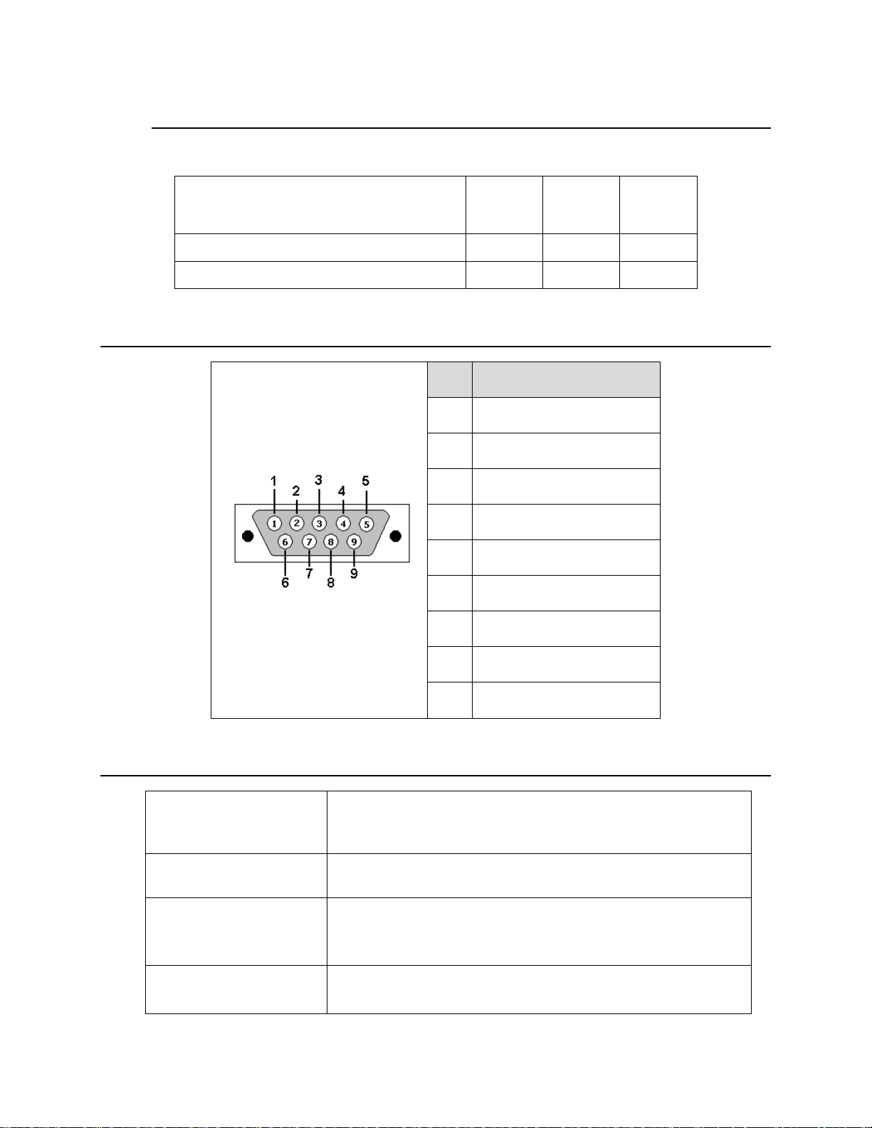
PIN
CONFIGURATION
1
+5 V
2
TXD
3
RXD
4
CTS
5
GND
6
RTS
7
N/C
8
RTS
9
N/C
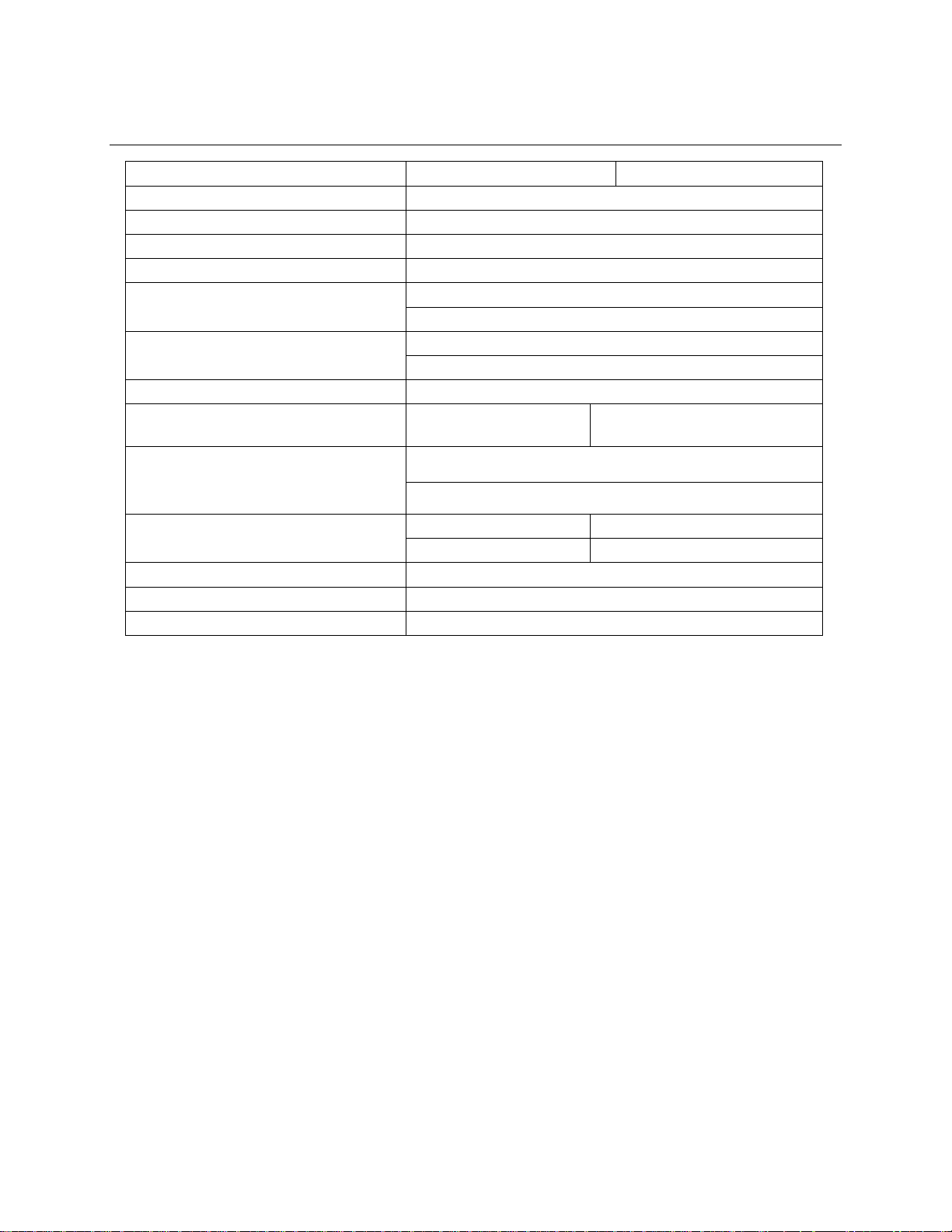
Physical dimensions
286 mm (W) x 259 mm (H) x 434 mm (D)
11.26 in (W) x 10.20 in (H) x 17.09 in (D)
Weight
11 kg (22 lbs)
Electrical
Internal switching power supply
Input: AC 100-240V, 50 - 60 Hz
Output: DC 24V 3.3A
Environmental condition
Operation: 5 ~ 40˚C (41 ~ 104˚F), 20~85% non-condensing
Storage: -40 ~ 60 ˚C (-40 ~ 140˚F), 10~90% non-condensing
The printer offers the following optional features.
RS-232C Pin Configuration
Printer Specifications
12
Page 13
Print Specifications
203 dpi models
300 dpi models
Printhead resolution
203 dots/inch (8 dots/mm)
300 dots/inch (12 dots/mm)
Printing method
Thermal transfer and direct thermal
Dot size
(width x length)
0.125 x 0.125 mm
(1 mm = 8 dots)
0.084 x 0.084 mm
(1 mm = 11.8 dots)
Print speed
(inches per second)
2, 3, 4, 5, 6 ips
2, 3, 4, 5, 6 ips
Max. print width
104 mm (4.10 in.)
Max. print length
2,512 mm (99 in.)
1,223 mm (48 in.)
Ribbon outside diameter
Max. 81.3 mm (3.2 in.)
Ribbon length
450 meter (1476 feet)
Ribbon core inside diameter
25.4 MM (1 in.)
Ribbon width
Max. 110 mm (4.33 in.)
Min. 40 mm (1.575 in.)
Ribbon wound type
Outside wound
Print Specifications
Ribbon Specifications
13
Page 14
Media Specifications
Media Specifications
203 dpi models
300 dpi models
Label roll capacity
203.2 mm (8 in.) OD
Media alignment
Edge alignment
Media type
Continuous, die-cut, black mark, fanfold, notch
Media wound type
Printing face outside wound
Media width (label + liner)
Max. 118 mm (4.6 in.)
Min. 25.4 mm (1.0 in.)
Media thickness (label + liner)
Max. 0.28 mm (0.0110 in.)
Min. 0.06 mm (0.023 in.)
Media core diameter
25.4 mm - 76.2 mm (1 in. ~ 3 in.)
Label length
(Tear-Off Strip, Continuous Mode)
5 - 2,286 mm (0.2 in. 90 in.)
5~1,016 mm (0.2 in. - 40 in.)
Label length (Peel-Off mode)
Max. 152.4 mm (6 in.)
Min. 25.4 mm (1 in.)
Label length (Cut mode)
Max. 2,512 mm (99 in.)
Max. 1,223 mm (48 in.)
Min. 25.4 mm (1 in.)
Min. 25.4 mm (1 in.)
Gap, notch, and hole height
Min. 2 mm (0.08 in.)
Black mark height
Min. 2 mm (0.08 in.)
Black mark width
Min. 8 mm (0.31 in.)
14
Page 15
2 Operations Overview
Unpacking and Inspection
This printer is packaged to withstand damage during shipping. Upon receiving, inspect the packaging and
printer. Keep all packaging materials in case you need to reship the printer.
Unpacking the Printer
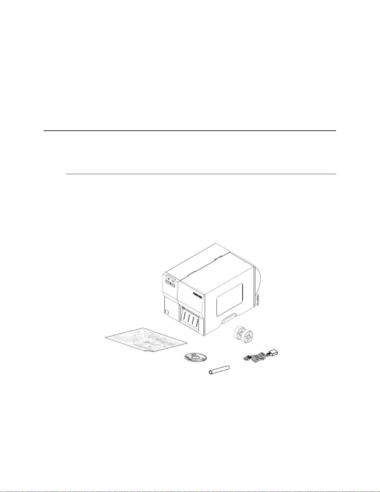
The following items are included in the carton:
Printer unit
Software/Windows driver CD disk
Quick Setup Guide
Power cord
Ribbon take up paper core
3” Media Core Adapters (2)
Figure 1. Printer Package Contents
If any parts are missing, contact the Customer Service Department of your purchased reseller or
distributor.
15
Page 16
1
2
3
4
7
5
6
1
A
A
Printer Overview
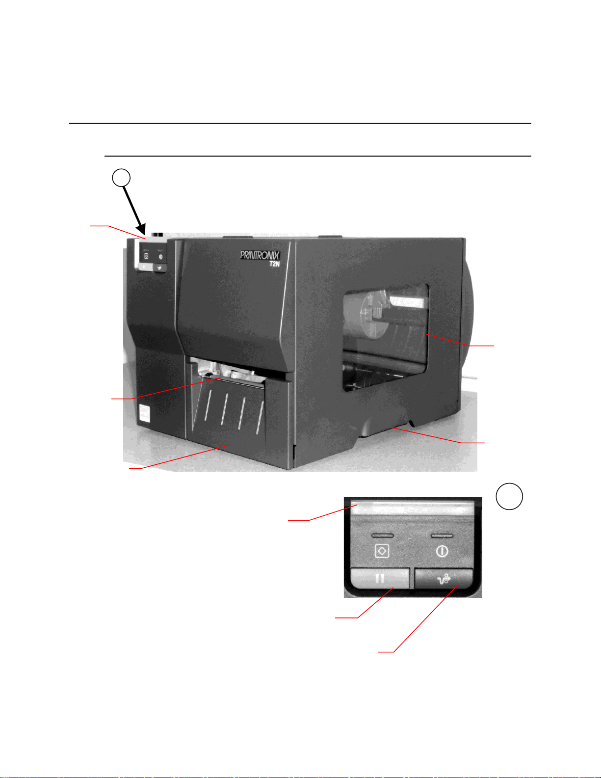
Front View
16
1. STATUS Indicator
2. Pause Key
3. Feed Key
4. Media Exit
5. Lower Front Cover
6. Media Window
7. Media Cover (Handle)
Figure 2. Printer Front View
Page 17
10
7
8
9
5
3
1
2
13
14
12
6
4
11
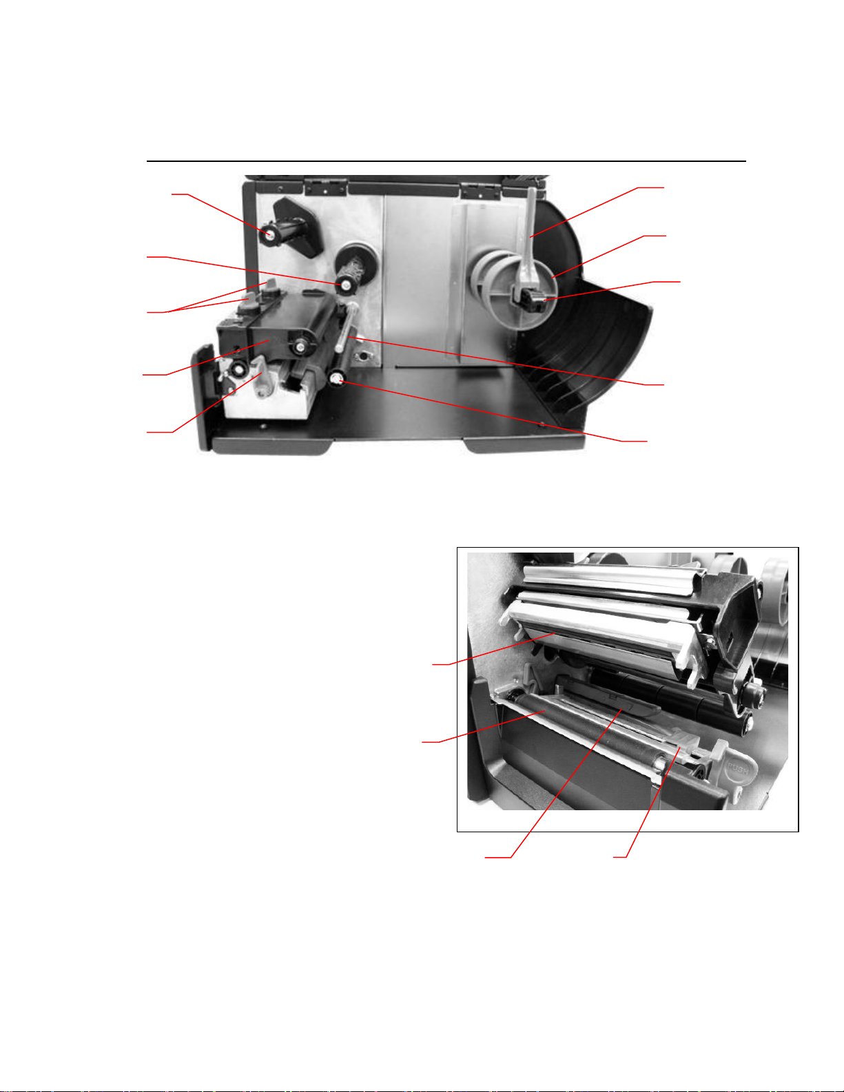
Interior View
1. Ribbon Take-Up Spindle
2. Ribbon Supply Spindle
3. Printhead Pressure Adjustment Knobs
4. Pivoting Deck
5. Deck Lock Lever
6. Label Roll Guide
7. 3” Core Adapters (2)
8. Media Hanger Beam
9. Ribbon Guide Bar
10. Media Guide Bar
11. Printhead
12. Platen Roller
13. Media Sensor
14. Label Width Guide
Figure 3. Printer Interior View
17
Page 18
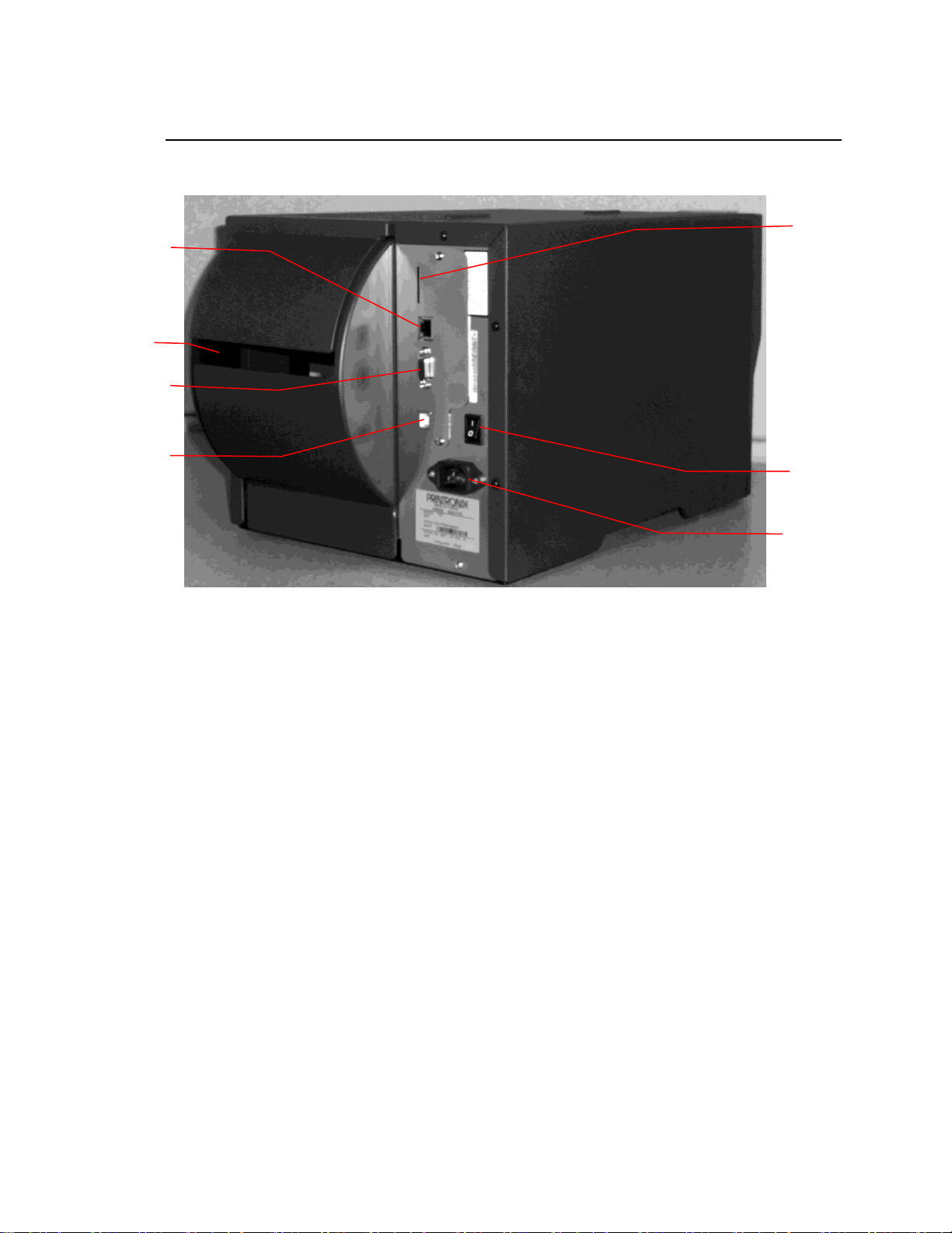
Rear View
2
4 1 5
6
3
7
1. Internal Ethernet Interface
2. Fanfold Label Entrance
3. RS-232C Interface (Max. 115,200 bps)
4. USB Interface (USB 2.0/ Full speed mode)
5. SD Card Slot*
6. Power Switch
7. Power Socket
NOTE: The interface picture is for reference only. Refer to the product specification for
interface availability.
*Recommended SD specification. See Table 1 on page 19.
Figure 4. Printer Rear View
18
Page 19
SD Card
Specification
SD Card
Capacity
Approved SD Card
Manufacturer
V1.0, V1.1
128 MB
SanDisk, Transcend
V1.0, V1.1
256 MB
SanDisk, Transcend, Panasonic
V1.0, V1.1
512 MB
SanDisk, Transcend, Panasonic
V1.0, V1.1
1 GB
SanDisk, Transcend, Panasonic
V2.0 SDHC CLASS 4
4 GB
V2.0 SDHC CLASS 6
4 GB
SanDisk, Transcend, Panasonic
V1.0, V1.1
microSD 128 MB
Transcend, Panasonic
V1.0, V1.1
microSD 256 MB
Transcend, Panasonic
V1.0, V1.1
microSD 512 MB
Panasonic
V1.0, V1.1
microSD 1 GB
Transcend, Panasonic
V2.0 SDHC CLASS 4
microSD 4 GB
Panasonic
V2.0 SDHC CLASS 6
microSD 4 GB
Transcend
V1.0, V1.1
miniSD 128 MB
Transcend, Panasonic
V1.0, V1.1
miniSD 256 MB
Transcend, Panasonic
V1.0, V1.1
miniSD 512 MB
Transcend, Panasonic
V1.0, V1.1
miniSD 1 GB
Transcend, Panasonic
V2.0 SDHC CLASS 4
miniSD 4 GB
Transcend
V2.0 SDHC CLASS 6
miniSD 4 GB
The DOS FAT file system is supported for the SD card.
Folders/files stored in the SD card should be in the 8.3 filename format.
Table 1. SD Card Specifications
19
Page 20
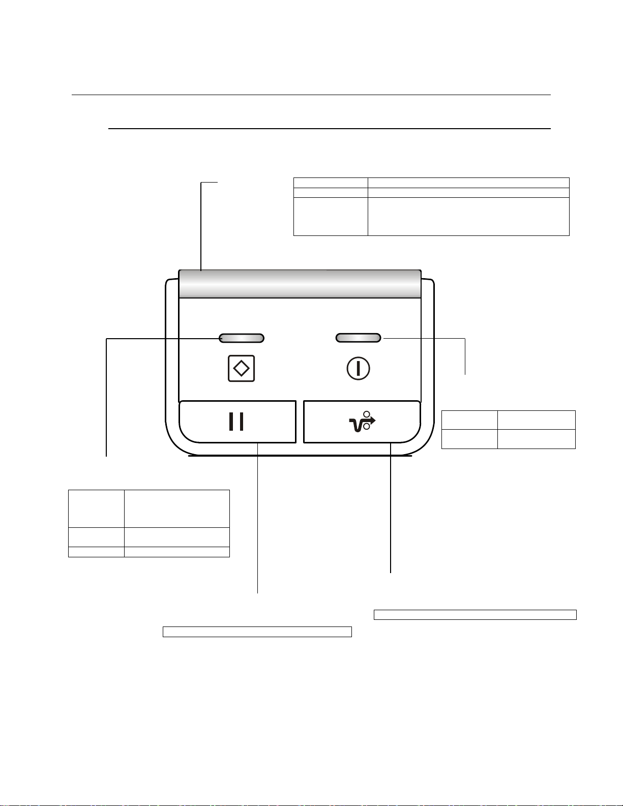
Operator Controls
Off
Printer is offline, no error.
On
Printer is online, no error.
Blinking
Printer is in error state:
Head Open, Paper Jam, Out of Paper,
Ribbon Errors, Cutter Error, Printhead Overheat,
Calibration Error
ONLINE Indicator
Off
Printer is offline and/or in
error state. The printer
can receive data while
offline.
On
The printer is online and
ready to process data.
Blinking
Printer is processing data.
PAUSE Key
Toggles printer between online and offline mode.
FEED Key
Printer advances media one label length if online.
STATUS Indicator
POWER Indicator
Off
Printer power is
turned off.
On
Printer power is
turned on.
Front Panel and Keys
20
Page 21
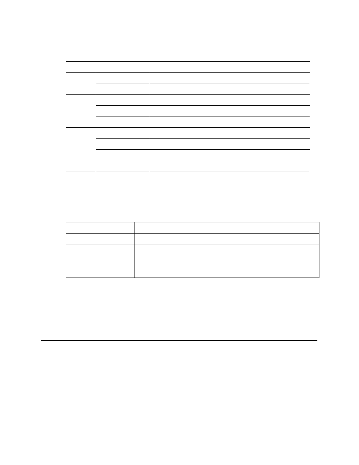
LED Indicators
LED
State
Indication
POWER
Off
Printer power is turned off.
On
Printer power is turned on.
ONLINE
Off
Printer is offline or error occurred.
On
Printer is online.
Blinking
Printer is receiving data.
STATUS
Off
Printer is offline.
On
Printer is online.
Blinking
Printer is in error state:
Head Open, Paper Jam, Out of Paper, Ribbon Errors,
Cutter Error, Printhead Overheat, Calibration Error
Key Combination
Function
FEED Key
Printer will power-up and print a test page.
PAUSE Key
Printer will power-up and by default, force Auto-Calibration
regardless of the configuration option. (See Chapter 5,
Media/Sensor tab on page 71).
FEED + PAUSE Keys
Printer will reset to its factory default parameters.
Special Power-Up Key Combinations
To simplify operation, a few functions can be performed by holding down certain keys at
power-up.
Clearing Data from the Buffers
This product does not have a CLEAR key or method of clearing the data within the internal
buffers. Turn the printer off/on to clear the buffer.
Setting Up the Printer
1. Place the printer on a flat, secure surface.
2. Ensure the power switch is off.
3. Plug the power cord into the AC power cord socket at the rear of the printer, then plug the power cord
into a properly grounded power outlet.
4. Connect the printer to the computer interface with the appropriate cable.
21
Page 22
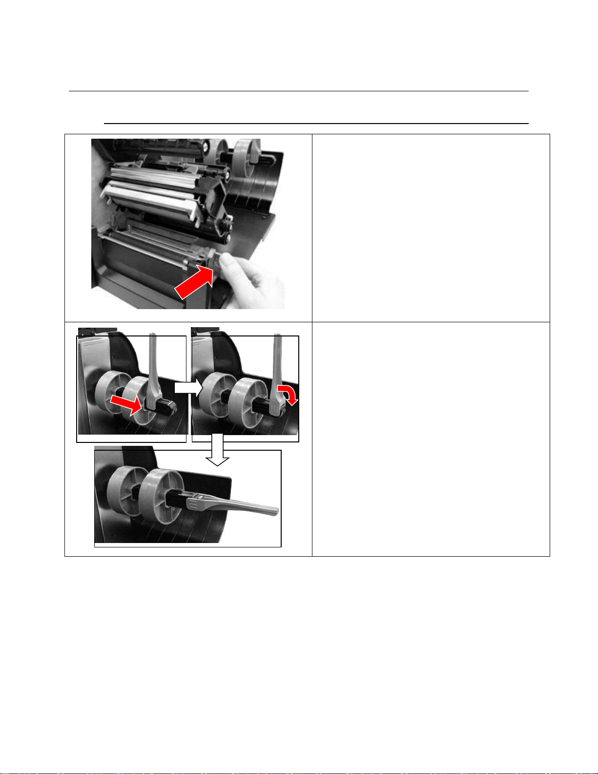
Ribbon Installation
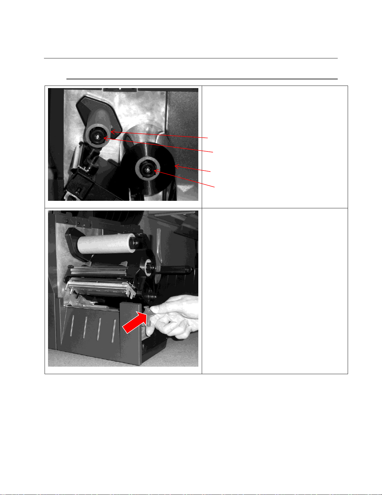
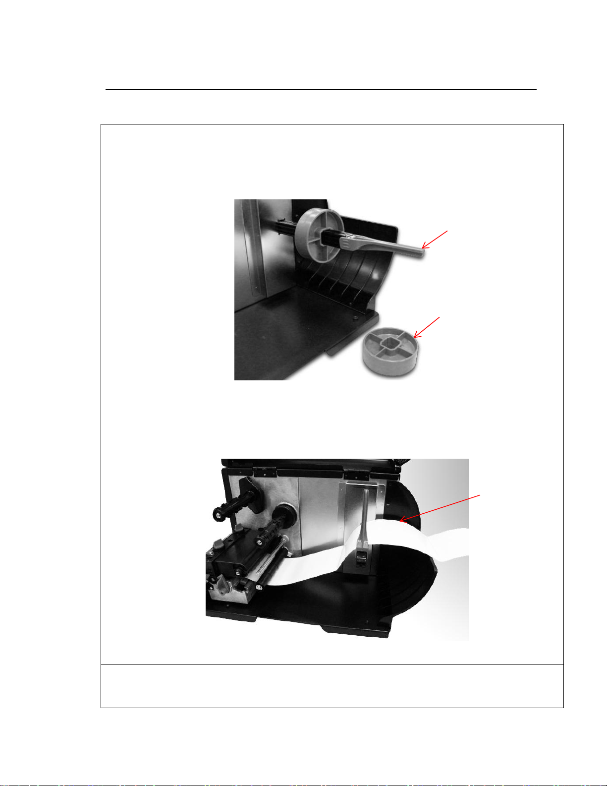
1. Open the printer media cover.
2. Load the ribbon onto ribbon supply spindle
and ribbon core onto ribbon take-up spindle.
3. Push the paper core and ribbon roll to the
inboard end of each spindle.
4. Push the deck lock lever back to open the
pivoting deck.
Ribbon Core
Ribbon Take-Up Spindle
Ribbon
Ribbon Supply
Loading Ribbon
22
Page 23
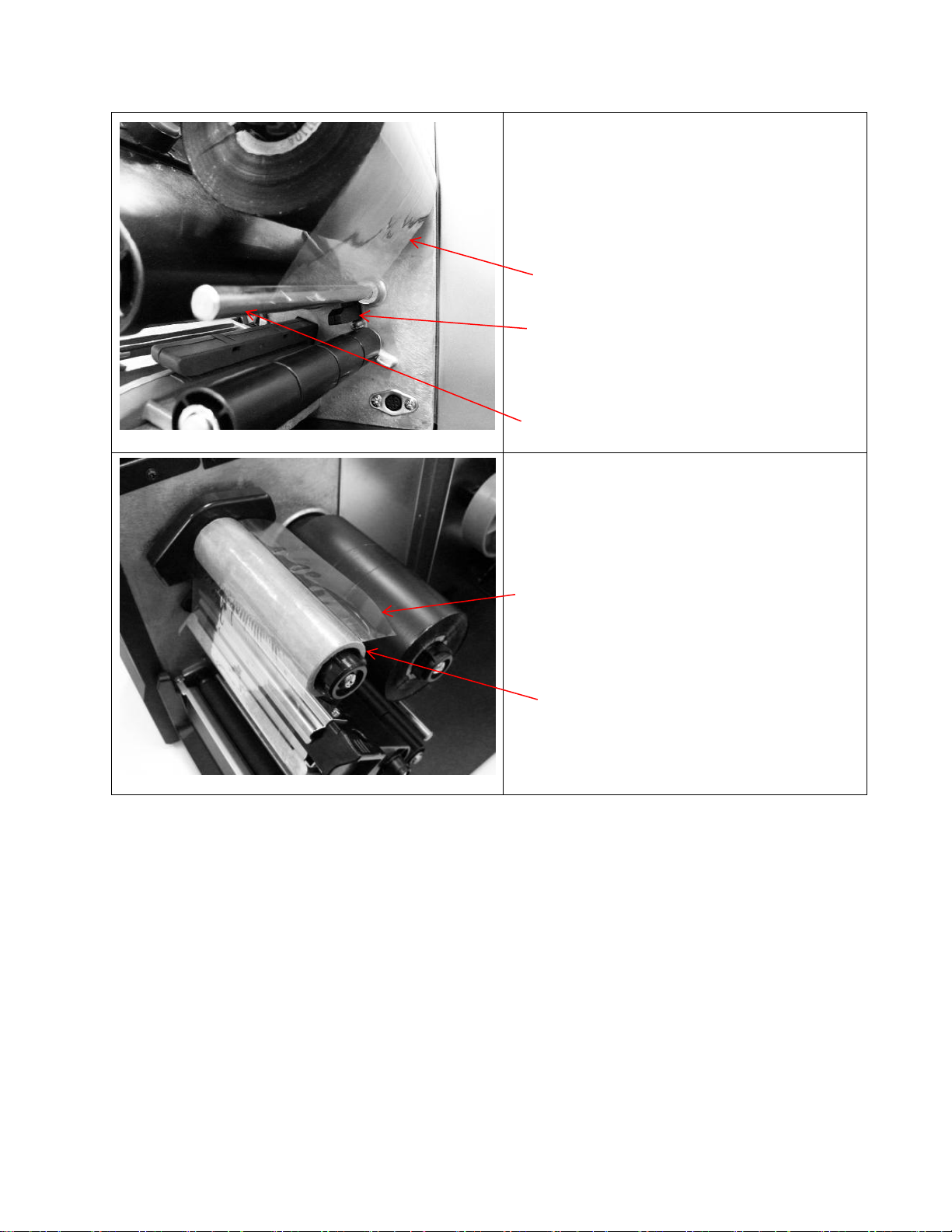
5. Thread the ribbon under ribbon guide bar and
through ribbon sensor slot. (See page 25 for
ribbon loading diagram or refer to diagram on
printer media cover.)
6. Tape ribbon leader onto ribbon core. Keep
ribbon wrinkle-free.
Ribbon Sensor
Ribbon Guide Bar
Ribbon Leader
Ribbon Core
Ribbon Leader
23
Page 24
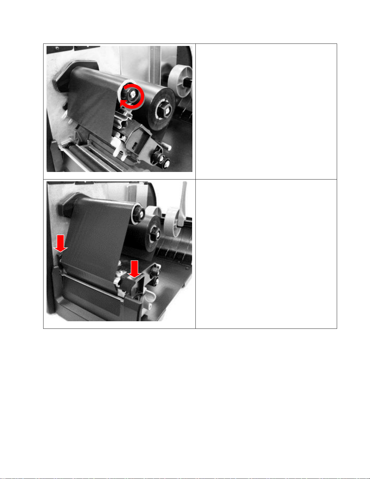
7. Rotate ribbon take-up spindle clockwise 3 to 5
full turns until ribbon is wrinkle-free.
8. Push both sides of the pivoting deck down to
close it, ensuring the latches engage properly.
Note: Pressing down only one side of the pivoting
deck may result in the pivoting deck opening
during printing. This can put the printer in an
unknown state. Be sure to push both sides of the
pivoting deck down and verify that the latch is in
locked position.
24
Page 25
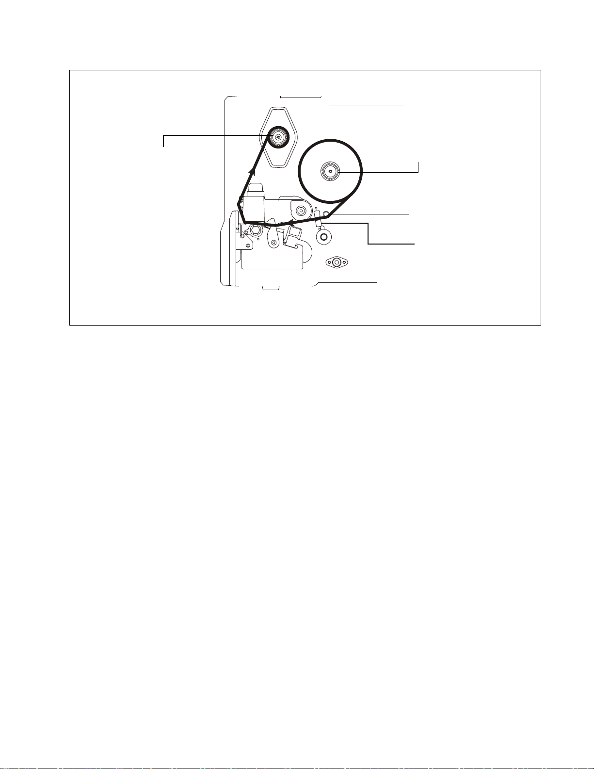
Ribbon Loading Path
Ribbon Take-Up
Spindle
Ribbon Guide Bar
Ribbon Supply
Spindle
Ribbon Sensor
Ribbon
25
Page 26
Media Installation
1. Open the media cover.
2. Push the deck lock lever back to open the
pivoting deck.
3. Move the label roll guide to the end of the media
hanger then place it in horizontal position. (If
paper core is 3 inches, install 3 inch core
adapters on the beam.)
See Note on next page.
Loading a Label Roll
26
Page 27
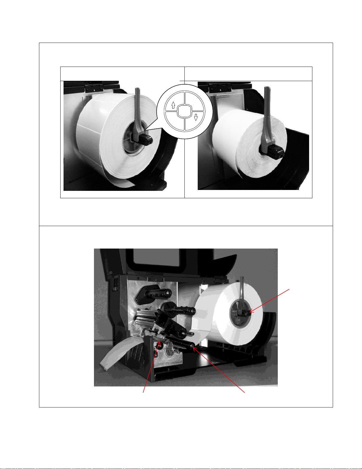
Note: For 3 inch core adapters, ensure arrows point vertical (see below). If using 1 inch core
media, remove the 3 inch core adapter from the media hanger beam.
3 inch media core
1 inch media core
4. Place media roll on hanger beam. Place label roll guide in up position.
5. Thread leading edge of label through media guide bar onto the platen roller.
Media Hanger
Beam
Media Guide Bar
Media Sensor
27
Page 28
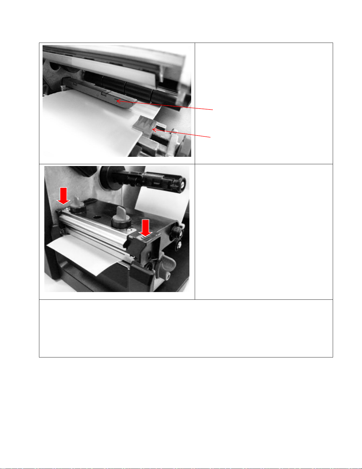
6. Adjust media width guide to fit label width.
Adjust media sensor ensuring the gap/black
mark passes underneath the media sensor
indicator (marked by a triangle) for sensing.
7. Push both sides of the pivoting deck down to
close it, ensuring the latches engage
properly.
Note: Pressing down only one side of the pivoting
deck may result in the pivoting deck opening
during printing. This can put the printer in an
unknown state. Be sure to push both sides of the
pivoting deck down and verify that the latch is in
locked position.
8. Use the Configuration Utility to set the media sensor type and calibrate the selected sensor.
Note:
Recalibrate the gap/black mark sensor when changing media.
The sensor location is marked by a triangle ▽ on the sensor housing.
The media sensor position can be moved horizontally. Ensure the gap or black mark is at the
location where media gap/black mark will pass through for sensing.
Media Sensor
Indicator
Media Width Guide
28
Page 29
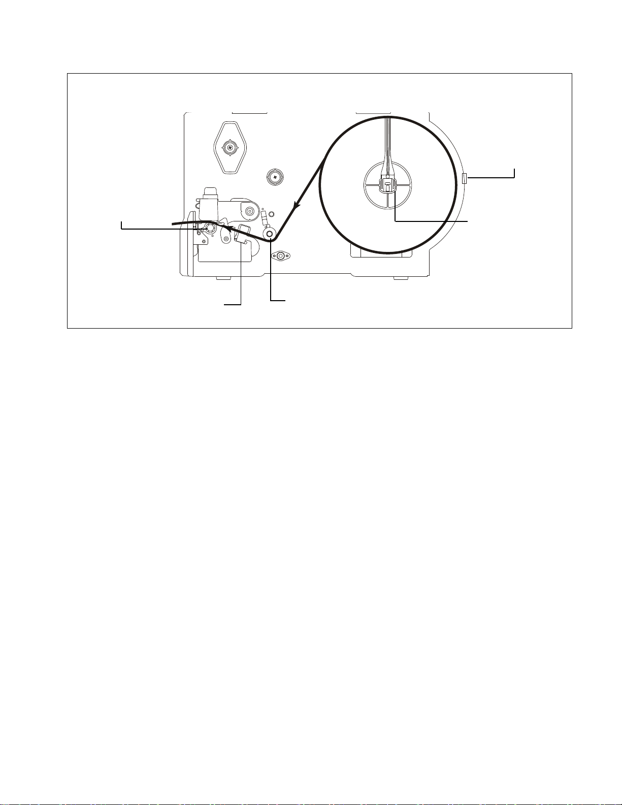
Label Roll Loading Path
Media sensor
Fanfold Media
Entrance Slot
Media Hanger
Beam
Media guide bar
Platen Roller
29
Page 30
Loading Fanfold Media
1. Open the printer media cover.
2. Push the deck lock lever back to open the pivoting deck.
3. Move the label roll guide to the end of media hanger beam then place roll guide to horizontal
position.
4. Remove the 3 inch core adapters from the media hanger beam.
5. Insert fanfold media through the rear label entrance slot.
6. Thread leading edge of fanfold label under the media guide bar onto the platen roller.
7. Adjust the media width guide to fit label width.
8. Push both sides of pivoting deck down to close it, ensuring the latches engage properly.
9. Use the Configuration Utility to set the media sensor type and calibrate the selected sensor.
Note: Calibrate the gap/black mark sensor when changing media.
Fanfold
Media
Label Roll
Guide
3 Inch Core
Adapters (2)
Fanfold media feeds through rear label entrance slot or opening.
30
Page 31

Loading Media in Peel-Off Mode
1. Open the peel-off cover by pulling down the tabs located on peel-off cover.
2. Install the label roll (see page 26).
3. Use the Configuration Utility to set the media sensor type and calibrate the selected sensor.
4. Pull label through front of printer and peel off a few labels, leaving the liner.
Liner
Label
31
Page 32

5. Feed the liner into the peel-off cover slot.
6. Close the peel-off cover and pivoting deck.
Label
Peel-off
Cover Slot
Liner
Liner
32
Page 33

7. Use the Configuration Utility to set the printer to Peel-Off mode. Peeling will automatically start.
Press the FEED key to test.
Note: Calibrate the gap/black mark sensor when changing media.
Liner
Label
33
Page 34

Loading Media in Cut Mode
1. Install the label roll (see page 26).
2. Thread the media through the paper cutter opening.
3. Adjust the media width guide to fit the label width.
4. Close pivoting deck ensuring the latches
engage properly.
5. Use the Configuration Utility to set the printer to Cutter mode. Press the FEED key to test.
Note: Recalibrate the gap/black mark sensor when changing media.
Paper Cutter Opening
34
Page 35

Printhead Pressure Adjustment Knobs
Adjust printhead pressure under these conditions:
1. Printing with thick media. If media thickness is larger than 0.19 mm, higher pressure is required to
achieve good quality printouts.
2. Printing with narrow media. If media width is less than 4 inches wide, the printhead pressure must
be adjusted to avoid ribbon wrinkles.
There are five levels of pressure adjustments. Level 1 is the minimum pressure and level 5 is the
maximum pressure.
Example: If the label width is 4 inches, set both printhead pressure adjustment knobs to the same level. If
the label is less than 2 inches wide, increase the left side printhead pressure by rotating the adjustment
knob clockwise and decrease the right side pressure by rotating the adjustment knob counterclockwise to
level 1.
Note: Refer to the diagram on page 53 to adjust the platen position to accommodate media thicker than
0.19 mm (0.0075 in).
35
Page 36

36
Page 37

3 Troubleshooting
Fault
Description
Calibration Error
The printer is unable to calibrate the Media properly.
Cutter Error
The printer has detected a cutter malfunction.
Out of Paper
The Media Sensor cannot find any media.
Paper Jam
The Media Sensor cannot find a gap, hole, or black line.
Head Open
The printer has detected that the pivoting deck is up (open).
Printhead Overheat
The printer has detected the print head is overheated.
Ribbon Encoder Err
The printer has detected the ribbon supply spindle is not turning.
Ribbon End Err
The Ribbon Sensor cannot detect a ribbon.
Fault Handling
When the STATUS indicator is blinking, a fault has occurred. In addition, the ONLINE indicator is off and
the printer is no longer processing jobs. In some cases, the reason for a fault can be determined by
visually inspecting the printer (e.g., out of paper). In other cases, the fault may be more subtle and require
investigation with the Configuration Utility.
This section discusses how faults can be identified, how the Configuration Utility can help, and
requirements to resolve the problem. The types of faults possible in the T2N are shown in Table 2.
Table 2. Types of Printer Faults
Identifying the Fault
Upon seeing the STATUS indicator blinking, quickly inspect the printer to identify the faults:
Is there media installed in the printer?
Is there a paper jam?
For thermal transfer configurations, is there a ribbon installed?
Is the Printhead open? Make sure the pivoting deck is securely closed on both sides.
Did the error occur immediately after the calibration procedure?
If possible, resolve the problem immediately using the guidelines shown in the Fault Recovery section on
page 39.
If the problem is not obvious or if attempts to resolve the problem did not work, use the Configuration
Utility to confirm the Fault type. After establishing connection with the printer (see Tool Interface on
page 61), click the “Get Status” button (see Figure 5 on page 38). This will confirm the fault type based on
Table 2 above.
37
Page 38

Figure 5. Obtaining Printer Status
Once the Configuration Utility identifies the fault, you can press the FEED Key on the printer to clear the
fault. See Fault Recovery on page 39 to resolve the issue.
For Calibration Error, Ribbon Err, Ribbon End Err, or Paper Jam errors, verify that the Media/Sensor
configuration is correct (see “Media/Sensor tab on page 71). Upload the configuration by doing a “Read”
operation. If the “Read” operation times out with a “Port Open Error” or “Data Transmission Error”, the I/O
channel may be blocked with a host job. In this case, cancel the print job on the host, reboot the printer,
and then perform the “Read” operation again to upload the configuration.
When the configuration has been uploaded, verify it is correct or make changes as necessary and save
those changes in the printer using the “Set” operation. If the fault persists, refer to Fault Recovery on
page 39 to resolve the issue.
38
Page 39

Fault Recovery
Printer Status Message
Recovery Procedure
Calibration Error
The printer is unable to calibrate the Media Sensor properly:
1. Verify that the Media Sensor, Label Length, and Max Cal Length
values set within the Configuration Utility match the installed media.
2. Open the pivoting deck.
3. Pull the media back onto the hanger beam.
4. Make sure the media sensor is clean (see Chapter 4, page 49).
5. Reload the paper making sure it is properly threaded through the
media sensor and the media width guide.
6. Make sure the media sensor is properly positioned with the triangle
in line with the gap, notch, hole, or black mark (see page 28).
7. Close the pivoting deck.
8. Press the Feed Key to clear the error.
9. Calibrate again either via the Configuration Utility (see “Calibrate
Sensor” on page 96) or power-up with the PAUSE key held down.
See Note at the end of Table 3 on page 41.
Cutter Error
Blade Open (down)
Blade Closed (up)
The printer detected a cutter malfunction:
1. Pause the print job.
2. Open the pivoting deck.
3. Unlatch the cutter and rotate it down. Inspect the cutter to determine
if the blade is in the open (down) position. See photographs on left.
4. If the blade is in the open (down) position and a label is stuck in the
cutter, remove it. Press the Feed Key to clear the error. Go to step 6.
5. If the blade is in the closed (up) position, turn the printer power off.
Wait 5 seconds then turn the printer power on. After the printer
finishes initialization the blade moves to the open (down) position.
Remove any label or debris stuck in the cutter.
6. Feed the media through the cutter slot, then close and latch the
cutter.
7. Close the pivoting deck.
8. Press the Feed Key to clear the error.
9. Resume printing.
Note: If a Cutter Error reoccurs, repeat steps 1 to 6, then use the
Configuration Tool “Cut Rev” function before resuming the print job. If
problems persist, use the “Cut Fwd” function.
See Note at the end of Table 3 on page 41.
Once the Configuration Utility identifies the fault, press the FEED key on the control panel to clear the
fault condition. This stops the STATUS indicator from blinking.
If the issues are not resolved after following the steps in Table 3, contact the Printronix Customer
Support Center (page 123).
Table 3. Printer Status Messages and Recovery Procedures
39
Page 40

Out of Paper
The Media Sensor detected a paper out condition.
1. Open the pivoting deck and reload the same type of media into
the printer.
2. Close the pivoting deck.
3. Press the Feed key to clear the error.
4. The printer should advance to the TOF of the next label and
resume printing.
See Note at the end of Table 3 on page 41.
The Media Sensor cannot find any media, but media is installed.
1. Verify that the Media Sensor, Label Length, and Max Cal
Length values set within the Configuration Utility match the
installed media.
2. Open the pivoting deck.
3. Reload the media making sure it is properly threaded through
the media sensor and the media width guide.
4. Make sure the media sensor is properly positioned with the
triangle in line with the gap, notch, hole, or black mark
(see page 28).
5. Close the pivoting deck.
6. Press the Feed Key to clear the error.
7. The printer should advance to TOF of the next label and
resume printing.
See Note at the end of Table 3 on page 41.
Paper Jam
The Media Sensor cannot find a gap, hole, or black mark:
1. Open the pivoting deck.
2. Pull the media back onto the hanger beam.
3. Make sure the media sensor is clean (see page 49).
4. Reload the paper making sure it is properly threaded through the
media sensor and the media width guide.
5. Make sure the media sensor is properly positioned with the triangle
in line with the gap, notch, hole, or black mark (see page 28).
6. Make sure the label size is set correctly.
7. Close the pivoting deck.
8. Press the Feed Key to clear the error.
9. The printer should advance to the TOF of the next label and
resume printing.
See Note at the end of Table 3 on page 41.
Head Open
The printer has detected that the pivoting deck is up:
1. Close the pivoting deck by pressing down firmly on both sides of
the pivoting deck until the latch fully engages.
2. Press the Feed Key to clear the error.
3. The printer should advance to the TOF of the next label and
resume printing.
See Note at the end of Table 3 on page 41.
40
Page 41

Printhead Overheat
The printer has detected that the printhead has overheated.
The printer will continue to monitor the printhead temperature. When
the printhead has sufficiently cooled, the printer will clear the error and
automatically resume printing. No operator intervention is required.
Ribbon Encoder Err
The printer has detected the ribbon supply spindle is not turning:
1. Open the pivoting deck.
2. Verify that the ribbon on the supply spindle is not loose or slack.
3. Verify that the ribbon is loaded correctly on the ribbon supply and
take-up spindles.
4. Verify that the ribbon is not broken between the ribbon supply and
take-up spindles.
5. Close the pivoting deck.
6. Press the Feed Key to clear the error.
7. The printer should advance to the TOF of the next label and
resume printing.
See Note at the end of Table 3 on page 41.
Ribbon End Err
The ribbon sensor cannot detect a ribbon.
The printer has run out of ribbon or the ribbon has broken at the
sensor:
1. Open the pivoting deck.
2. Install new ribbon and verify that the ribbon is loaded correctly on
the ribbon supply and take-up spindles.
3. Verify that the ribbon is threaded properly through the ribbon
sensor.
4. Close the pivoting deck.
5. Press the Feed Key to clear the error.
6. The printer should advance to the TOF of the next label and
resume printing.
See Note at the end of Table 3 on page 41.
Note: If Fault Reprint = Enable, the printer will reprint the label that was printing when the fault was
detected.
Printer Configuration
Knowing the current printer configuration is necessary to diagnose and correct unexpected printer
behavior. The Configuration Utility may be used to read the current printer configuration or to print the
configuration by clicking the Print Test Page button. In cases where the Configuration Utility is not
available or unable to communicate with the printer, you may print the configuration by turning off the
printer, then holding down the Feed Key on the Control Panel while turning the printer back on.
41
Page 42

Common Problems
Problem
Possible Cause
Recovery Procedure
Power indicator does not
illuminate.
The power cord is not properly
connected.
1. Plug the power cord in
printer and outlet.
2. Verify that the outlet has
power.
3. Switch power on.
Status indicator is blinking and
Online indicator is off.
The printer is in a fault condition.
See Fault Handling on page 37.
The Configuration Utility “Get
Status” shows “Head Open”.
The printer pivoting deck is open.
See the “Head Open” recovery
procedure on page 40.
The printer status from the
Configuration Utility shows
“Ribbon End Err.” or “Ribbon
Encoder Err.”
The printer has run out of ribbon
or the ribbon is installed
incorrectly.
See the “Ribbon End Err” or
“Ribbon Encode Err” recovery
procedure on page 41.
The printer does not report “Print
head Open” fault when the
printer is first powered on.
This is not a problem. The printer
will only report this fault when
attempting to print or calibrate.
Use both hands to close the
pivoting deck by firmly pressing
down on the recess on both
sides of the deck until it snaps
into place.
Media Calibration is followed
immediately by a fault (Status
LED blinking).
Media incorrectly loaded.
Media sensor assembly out
of position.
Media lenses are obstructed
with paper dust.
See the “Calibration Error”
recovery procedure on page 41.
The printer status from the
Configuration Utility shows “Out
of Paper”.
The printer has run out of
labels.
The labels are installed
incorrectly.
The Gap/Mark sensor is not
calibrated.
See the “Out of Paper” recovery
procedure on page 41.
The printer status from the
Configuration Utility shows
“Paper Jam”.
Gap/black mark sensor is not
set properly.
Ensure the paper label size
is set properly.
Labels may be stuck inside
the printer mechanism.
See the “Paper Jam” recovery
procedure on page 40.
The printer status from the
Configuration Utility shows
“PrintHead Overheat”.
Printhead temperature reached a
high level and needs to cool
down.
See the “Printhead Overheat”
recovery procedure on page 41.
The following table lists common problems that may occur when operating the printer. If the problem still
exists after troubleshooting, contact the Customer Service Department of your purchased reseller or
distributor.
42
Page 43

The printer status from the
Configuration Utility shows
“Cutter Error”.
Cutter is unable to turn due to
jamming.
See the “Cutter Error” recovery
procedure on page 39.
Printer not printing.
Cable is not well connected
to serial or USB interface, or
Ethernet port.
The serial port cable pin
configuration is not pin to pin
connected.
1. Reconnect cable to interface.
2. If using serial cable:
a. Replace the cable
with pin to pin
connection.
b. Check the baud rate
setting. The default
setting is 9600, n, 8,
and 1.
3. If using the Ethernet cable:
a. Ensure the Ethernet
RJ-45 connector
green LED is lit.
b. Ensure the Ethernet
RJ-45 connector
amber LED is
blinking.
c. Ensure the printer
has the IP address
when using DHCP
mode.
d. Wait a few seconds
to allow for printer
communication with
the server, then
check the IP address
setting again.
4. Check for the ribbon inked
side out placement.
5. Reload the ribbon.
6. Clean the printhead.
7. Check the print density
setting.
8. The printhead’s harness
connector is not properly
connected to the printhead.
Turn off the printer and
reconnect the plug connector
again.
43
Page 44

Memory full (FLASH/DRAM)
FLASH/DRAM is full.
Delete unused files in the
FLASH/DRAM. Use the
Configuration Utility to change
the maximum value (see
Advanced Setup on page 111).
Unable to use SD card.
SD card was inserted after
powering printer on.
SD card is damaged.
SD card does not insert
properly.
Unapproved SD card in use.
1. Use an authorized SD card.
For supported SD cards,
see page 19.
2. Reinsert the SD card and
power-up the printer.
Poor print quality.
Ribbon and media are
loaded incorrectly.
Dust or adhesive
accumulation on the
printhead.
Print density is not set
properly.
Printhead element is
damaged.
Ribbon and media are
incompatible.
Printhead pressure is not set
properly.
1. Reload supplies.
2. Clean the printhead.
3. Clean the platen roller.
4. Adjust the print density and
print speed.
5. Run a printer self-test and
check the printhead test
pattern for missing dots.
6. Change to proper ribbon or
label media.
7. Adjust the printhead
pressure adjustment knobs.
If the left or right side of the
printout is too light, adjust the
left or right pressure
adjustment knob to the
higher index for higher
pressure. If the pressure
adjustment knob is adjusted
to 5 and the print quality is
still poor, contact the
Customer Service
Department of your reseller
or distributor for service or
instructions.
8. Ensure the deck lock lever is
latched to the pivoting deck
properly.
Cutter is not working.
The connector is loose.
Plug the connector cable
correctly.
44
Page 45

Label feeding is not stable
(skew) when printing.
The media guide does not touch
the edge of the media.
1. If the label is moving to the
right side, move the media
width guide to the left
(inboard).
2. If the label is moving to the
left side, move the media
width guide to the right
(outboard).
Skip labels when printing.
Label size is not specified
correctly.
Sensor sensitivity is not set
properly.
The media sensor is covered
with dust.
1. Ensure the label size is set
correctly.
2. Calibrate the sensor by Auto
Gap or Manual Gap options.
3. Clean the Gap/Black mark
sensor (refer to Chapter 4 on
page 49).
The printing position on small
labels is incorrect.
Media sensor sensitivity is
not set properly.
Label size is incorrect.
The parameter Shift Y in the
LCD menu is incorrect.
The vertical offset setting in
the driver is incorrect.
1. Recalibrate the sensor
sensitivity.
2. Set the correct Label Length
size and gap size.
3. If the Label Length is correct
use the Configuration Utility
to adjust Vert Image Shift.
The left side printout position is
incorrect.
Wrong Label Width size setup.
Set the correct label size. If the
label size is correct, use the
Configuration Utility to adjust
“Horz Image Shift.”
Missing printing on the left or
right side of label.
Wrong Label Width size setup.
Set the correct label size.
Configuration Utility requests
password when communicating
with the printer.
A password previously set from
the Configuration Utility is lost.
Contact the Printronix Customer
Support Center (page 123) to
request help on unlocking the
printer.
Power and Error LEDs are
blinking fast.
Power was switched OFF and
ON too quickly.
Power off the printer and wait for
all LEDs to turn off. Power on the
printer again.
Wrinkle problem.
Printhead pressure is
incorrect.
Ribbon is incorrectly
installed.
Media is incorrectly installed.
Print density is incorrect.
Media feeding is incorrect.
1. See page 46 for more
information on ribbon
wrinkles.
2. Set the density to achieve
good print quality.
3. Ensure the media width
guide just touches the
outside edge of the media.
Gray line on the blank label.
The printhead is dirty.
The platen roller is dirty.
1. Clean the printhead.
2. Clean the platen roller (refer
to Chapter 4 on page 49).
Irregular printing
The printer is in Job Capture
mode.
The RS-232 is incorrect.
1. Turn the printer off and on to
exit Job Capture mode..
2. Reset the RS-232 setting.
45
Page 46

Mechanism Fine Adjustment to Avoid Ribbon Wrinkles
Adjustable
Printer
Parts
Symptom
Wrinkle occurs in lower right to upper left
direction.
Wrinkle occurs in lower left to upper right
corner.
Wrinkle
Example
Feed direction
This printer has been fully tested before delivery. There should be no evidence of ribbon wrinkles on
printed labels. Ribbon wrinkle is related to the media thickness, printhead pressure balance, ribbon film
characteristics, print darkness setting and more. If the ribbon wrinkles, follow the instructions below to
adjust printer components.
46
Page 47
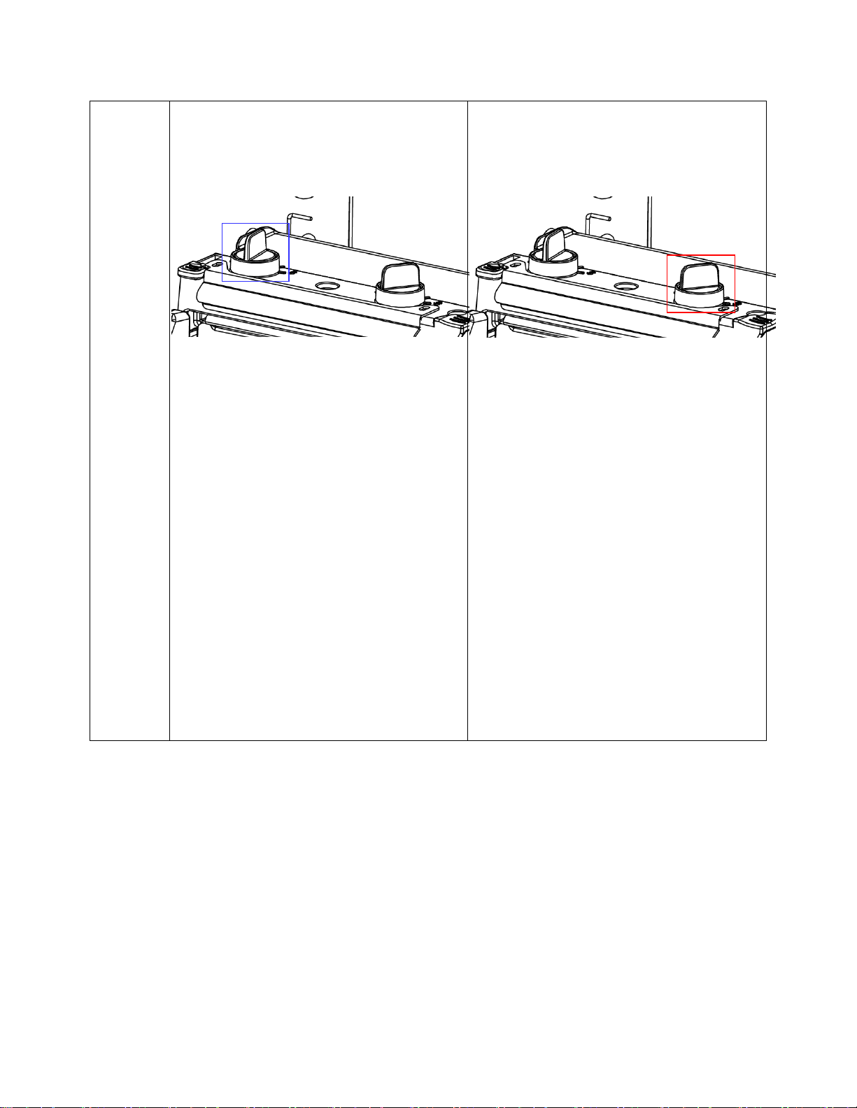
Adjust the printhead pressure adjustment knob.
The printhead pressure adjustment knob has
five setting levels. Clockwise adjustment
increases the printhead pressure. Counter
clockwise adjustment decreases the printhead
pressure.
If the wrinkle on the label starts from the lower
right side to upper left side, do following:
1. Decrease the left side printhead
pressure adjustment knob setting one
level per each adjustment then print the
label again to check for wrinkles.
2. If the left side printhead adjustment knob
level is set to index 1 (the lowest
pressure index), increase the right side
printhead pressure.
3. If the wrinkle still exists, contact the
Customer Service Department of your
reseller or distributor for service.
Adjust the printhead pressure adjustment knob.
The printhead pressure adjustment knob has
five setting levels. Clockwise adjustment
increases the printhead pressure. Counter
clockwise adjustment decreases the printhead
pressure.
If the wrinkle on the label starts from the lower
left side to upper right side, do following:
1. Decrease the right side printhead
pressure adjustment knob setting one
level for each adjustment then print the
label again to check for wrinkles.
2. If the right side printhead adjustment
knob setting is set to index 1 (the lowest
pressure index), increase the left side
printhead pressure.
3. If the wrinkle still exists, contact the
Customer Service Department of your
reseller or distributor for service.
Left knob
Right knob
47
Page 48

48
Page 49

4 Maintenance
Printer Part
Method
Interval
Printhead
1. Always power off the printer before
cleaning the printhead.
2. Allow the printhead to cool for a
minimum of one minute.
3. Use a cotton swab or a thermal
printhead cleaning pen and 100%
ethanol or 99.7% isopropyl alcohol
to clean the printhead surface.
Clean the printhead when changing a new
label roll (Direct Thermal Print Mode) or when
replacing the ribbon roll (Thermal Transfer
Print Mode).
Platen Roller
1. Turn the power off.
2. Rotate the platen roller and wipe it
thoroughly with 100% ethanol
alcohol and a cotton swab, or a lint
free cloth.
Clean the platen roller when changing a new
label roll.
Printhead Cleaning Pen
Printhead
Printhead
Elements
Elements
This chapter discusses how to maintain your printer.
1. Use one of the following materials to clean the printer:
Cotton swab or authorized Printronix Thermal Printhead Cleaning Pen (203502-002)
Lint-free cloth
Vacuum/Blower brush
100% Ethanol or 99.7% Isopropyl alcohol
2. The cleaning process is as follows:
49
Page 50

Tear Bar/Peel Bar
Use a lint-free cloth with 100% ethanol
alcohol to wipe the tear bar/peel bar.
Clean as needed.
Sensor
Use a vacuum or compressed air.
Clean monthly.
Exterior
Wipe the exterior with a damp cloth.
Clean as needed.
Interior
Brush or vacuum the interior.
Clean as needed.
CAUTION: Do not touch the printhead to avoid getting fingerprints on it. If unavoidable, use
ethanol alcohol or a thermal printhead cleaning pen to clean the printhead. Use 100% ethanol or
99.7% Isopropyl alcohol. DO NOT use rubbing alcohol, which can damage the printhead.
50
Page 51

Replacing the Platen Roller Assembly
1. Open printer media cover.
2. Push the deck lock lever to raise the pivoting deck.
3. Remove screw and the lower front cover.
4. Remove screw on the platen right side bushing.
Screw
Screw
Lower Front
Cover
51
Page 52

5. Disengage the platen left side bushing tab from the printer.
6. Remove the platen bushing and old platen roller assembly.
7. Replace the platen roller assembly.
Platen Roller Assembly
Right Side
Bushing
Left Side
Bushing Tab
52
Page 53

8. Reassemble the parts in reverse order.
For regular labels
0.06 mm (0.00236 in.) to
0.19 mm (0.0075 in.) thick
For thick labels
0.19 mm (0.0075 in.) to
0.28 mm (0.011 in.) thick
IMPORTANT: Ensure that both the left and right side bushing tabs are in the same
orientation. The printer will not be able to print properly if the left and right side bushing
tabs are not aligned.
53
Page 54

Replacing the Printhead Assembly
1. Open printer media cover.
2. If necessary, remove the used ribbon take-up roll from its spindle.
3. Remove the frame thumbscrew.
4. Remove the printhead thumbscrew.
Frame Thumbscrew
Printhead
Thumbscrew
54
Page 55

5. Push the deck lock lever to release the pivoting deck.
6. Carefully disconnect the printhead cable assembly from the printhead by pulling out the
connector.
IMPORTANT: Do not pull on the cables.
7. Replace the printhead assembly.
8. Connect the printhead cable and carefully lift the assembly into the pivoting deck.
9. Align the printhead assembly holes with the tenons, then insert.
IMPORTANT: Push the cables back underneath pivoting deck cover. Do not block the
ribbon path, otherwise the ribbon could bulge and cause wrinkles.
Printhead
Connector
Printhead
Assembly
Printhead
Assembly
Cables
Tenons
Printhead
Assembly
Holes
55
Page 56

10. Close the pivoting deck and ensure the levers engage properly. Install the new thumbscrew
(provided in every printhead assembly kit) to secure the printhead.
11. Open and close the pivoting deck ensuring the latches continue to engage properly.
Thumbscrew
56
Page 57

5 Configuration Utility
This chapter discusses the Configuration Utility application and how it can be used to operate and
configure your printer.
Access
You can obtain the Configuration Utility or upgrades in the following ways:
From the CD included with the T2N printer. Place the CD in your computer and follow the guide.
From the Printronix website http://www.printronix.com/products/drivers.aspx.
For Configuration Utility upgrades (if available), click the HELP button and select Utility and
Drivers to open a browser to http://www.printronix.com/products/drivers.aspx. Download the
utility.
The Configuration Utility is contained in a zip file as part number.zip.
System Requirements
System requirements for the Configuration Utility are:
32-bit Windows Operating System: Win2K, Windows XP, Vista, Windows 7
64-bit Windows Operating System: Windows XP, Vista, Windows 7
Hard Drive: 2 MB Free
Note: The Configuration Utility is not supported on Linux or Unix systems.
57
Page 58

Installing the Application
The Configuration Utility is contained in a zip file as part number.zip. The zip file will contain four
elements:
1. Configuration Utility file (.exe)
2. Compiled Help files (T2NHelp.chm)
3. PDF file (T2NHelp.pdf)
4. Readme file (.txt).
Installation is not necessary. Simply extract the contents of the zip file into the desired directory or
location then launch the application .exe file.
IMPORTANT: Extract contents of the zip file into the local C directory of your laptop or PC to have
access to the automated HELP contents within the Configuration Utility.
The application name follows the format ConfigUtil_vm_xxY.exe where vm_xxY represents the version
number of Vm.xxY as described in the Version Number section (see below). The included version number
allows the user to have several different versions of the Configuration Utility.
The T2N Configuration Utility can be launched with the icon which is copyrighted for use with this
application. The icon is Copyright © 2013 Printronix, INC. All Rights Reserved.
Launching the Application
Double-click the icon or execute ConfigUtil_vm_xxY.exe from a Windows command prompt.
The application will open as shown in Utility Overview (page 59).
Version Number
The Configuration Utility’s functionality and configuration change in conjunction with the firmware. Each
Configuration Utility release has a version number with format: Vm.xxYY where:
V = version
m = main version level (used to identify major updates)
xx = compatibility level (version for compatibility level)
YY = A-Z, AA-ZZ (letter for minor updates)
The T2N firmware will also have a similar version number format. The rules and limitations regarding
interaction between different firmware and Configuration Utility versions are discussed in the Compatibility
Challenges section (see page 68).
58
Page 59

Utility Overview
Printer Configuration
HELP Tool InterfaceLanguage Selection Units (Configuration)
File Manager
Command Tool
Advanced
Language Selection
HELP
Units (Configuration)
Tool Interface
Printer Configuration
File Manager
Command Tool
Advanced
Figure 6 is an overview of the Configuration Utility.
Figure 6. Configuration Utility Components
Language Selection. The utility interface is available in different languages: English,
Simplified Chinese, Traditional Chinese, Korean, German, Spanish, French, Italian, and
Portuguese. All headings and configuration parameters are translated; numerical values remain
the same. See Language Selection on page 60.
HELP. The HELP button offers easy access to support, including help contents with indexing and
searching, and links for Configuration Utility upgrades. HELP content is in English only. See
HELP on page 118.
Tool Interface. The Tool Interface provides options for Configuration Utility communication with
the printer. This is different from how the printer communicates with the host system in real
application environment. See page 61 for more information.
Printer Configuration (first tab). The Printer Configuration section supports configuration upload
and download, performs a number of actions, and retrieves printer status. Unit options include
inch or mm. See Printer Configuration on page 63.
File Manager (second tab). The File Manager section allows you to view, upload, and download
files to and from printer memory devices (DRAM, FLASH, and SD card). See File Manager on
page 106.
59
Page 60

Command Tool (third tab). This Command Tool section is for diagnostics and simple tests.
Users can create simple jobs or load jobs from files and send them to the printer for testing.
See Command Tool on page 109.
Advanced (fourth tab). The Advanced section provides advanced configuration options, including
memory allocation, scalable font control, statistics control, and text printing through PGL. It is
unnecessary to use this section for basic setup procedures. See Advanced Setup on page 111.
Language Selection
Language selection is available as a drop-down menu in the upper-left corner. Available
languages include: English (default), Simplified Chinese, Traditional Chinese, Korean, German,
Spanish, French, Italian, and Portuguese (see Figure 7). All labels and configuration options are
translated. Numerical values remain 0-9 (decimal) and 0-F (hexadecimal).
Figure 7. Selecting a Display Language
IMPORTANT: Some languages such as Traditional Chinese, Simplified Chinese, and
Korean require special fonts and characters sets to display properly. To use these
languages, your PC or laptop must be configured properly for the right region/language.
On Windows 7 systems, the region and language is chosen as follows:
1. Go to the Start Menu and open the Control Panel.
2. Launch the application.
3. Go to the Administrative tab and click “Change system locale …” .See Figure 8 (page 61).
4. Select the desired language:
a. For Simplified Chinese, choose “Chinese (Simplified, PRC)”.
b. For Traditional Chinese, choose “Chinese (Traditional, Taiwan)”.
c. For Korean, choose “Korean (Korea)”.
5. Follow the instructions, reboot if necessary.
60
Page 61

After proper configuration, the language selected becomes the default language when the
Configuration Utility is launched.
Tool Interface
Tool Interface selection is available as a drop-down menu in the upper-right corner. This option
allows you to choose communication I/O options with the printer: USB (the default), COM, or
ETHERNET. If the printer is connected to a PC with USB interface, launching the application will
automatically read the configuration settings from the printer and populate the fields. This
interface selection may be different from the interface sending print jobs. For example, a user
may want to select USB or COM with a laptop to configure the Ethernet parameters for a live
application environment. Alternatively, the user may prefer USB for both the Tool Interface and
the live application.
Figure 9 shows the Tool Interface section with the “Setup” window open to configure the selected
I/O. When USB is selected, no setup is required. For the COM (RS-232 serial), see Figure 9 for
setup options. If ETHERNET is selected, no setup is required. However, Ethernet setup within the
Interface Tab must be configured. Once the Tool Interface type is selected and setup is complete,
the Configuration Utility is ready to use.
Figure 8. Changing System Locale
Figure 9. Tool Interface Setup
61
Page 62

USB Connection
COM Port
Select COM1 to COM30. The default is COM1.
Baud Rate
Sets the baud rate of the serial interface. Baud rate is the speed at which
serial data is transferred between the host computer and the printer.
Choices are 1200, 2400, 4800, 9600 (default), 19200, 38400, 57600, or
115200.
Data Bits
Select the serial data word length, 7 or 8 (default).
Parity
Select None (default), Odd, or Even.
Stop Bit(s)
The number of stop bits in the serial data word. Select 1 (default) or 2.
Flow Control
Select None, Hardware (default), or Xon/Xoff.
When Xon/Xoff is selected, the printer controls the communication flow from
the host by turning the transmission on and off. In some situations, such as
when the buffer is full or the timing of signals is too slow or too fast, the printer
will tell the host to stop transmission by sending an XOFF character. The data
does not have any End of Text codes; Xon/Xoff is not a blocking protocol.
USB is default interface for the Configuration Utility. Since no setup is required with USB, the
Setup button is grayed out.
COM (RS-232) Connection
When COM is selected, click the Setup button to open the dialog box as shown in Figure 9
(page 61). The following parameters configure how the computer running the Configuration Utility
communicates with the printer:
Note: The default settings for COM within Setup should match the printer factory default for
RS-232. Before modifying these settings, test the connection with the printer using the default
settings.
Ethernet Connection
When Ethernet is selected, no setup is required from the Tool Interface section. However,
Ethernet setup within the Interface Tab must be configured before communication can begin. See
Ethernet Connection for instructions on how connect to the network (page 80).
62
Page 63

Test the Connection
Once Tool Interface selection is complete, click the Read button in the lower-right corner (see Figure 6,
page 59) to upload the printer’s current configuration into the Configuration Utility fields. For USB
connection, this process is automatic.
If the Configuration Utility is working properly, the “Communicating…” progress bar appears and the
Printer Configuration values will be populated. If communication is not working properly, an error will
display indicating “Port Open Error” or “Data Transmission Error”.
If communication problems persist, change the Tool Interface to USB. This is the easiest method of
establishing communication with the printer. Once communication is established, click “Read” to upload
the configuration. Check the Interface Tab settings if necessary.
Printer Configuration
Four main sections are available in the Configuration Utility, each is represented as a tab at the top level.
Figure 10 below shows the Printer Configuration tab.
Figure 10. The Printer Configuration Tab
Printer Configuration displays when the Configuration Utility is launched. Components of this section
include:
Printer Information. This subsection displays information about the T2N printer currently
connected to the Configuration Utility. See Printer Information for more details (page 64).
63
Page 64

Printer Configuration Tabs. This subsection allows users to set up and store a configuration in
Tab
Description
Media/Sensor
Configures all label and sensor settings.
Interface
Configures the host I/O, including serial and Ethernet.
PGL
Configures PGL settings.
ZGL
Configures ZGL settings.
EGL
Configures EGL settings.
the T2N printer. The available tabs for configuration include:
Printer Functions. This subsection consists of a set of buttons used to perform setup actions
(e.g., Calibrate Sensor and Active Emulation), diagnostics, and other important features such as
firmware upgrade. See Printer Functions on page 95 for more details.
Printer Status. This subsection queries the printer regarding status (e.g., Ready, Head Open,
Paper Jam, Out of Paper, etc.). See Printer Status on page 104 for more details.
Printer Information
Figure 11 shows printer information. Upon clicking the “Read” button, the printer’s information
populates the Configuration Utility. All items shown are read-only and cannot be modified. This
section describes the fields in greater detail.
IMPORTANT: If you contact the Printronix Customer Support Center for technical support,
report these field values for prompt handling.
Version
The Version consists of the model name, program file version, program file date, and program file
part number. The model name is T2N2 = 203 DPI, T2N3 = 300 DPI. The program file version is in
Printronix format Vm.xxYY. See Version Number on page 58 for information on Vm.xxYY format.
Note: When contacting the Customer Support Center, use the program file part number to
identify the software.
Serial No.
Serial No. is the serial number of the printer set in the Factory.
DPI
The printer DPI value (203 or 300 DPI) displays in this field.
Figure 11. Printer Information Values
64
Page 65

Printer Usage
The Printer Usage value is in inches only and cannot be reset. If a new controller is installed, this
figure will reset to the value on the new controller.
Configuration Overview
You can configure printer setup through the Configuration Utility or the webpage (when network is
used). The T2N printer contains two configurations:
Factory Configuration
User Configuration.
Factory Configuration parameters cannot be changed. User Configuration values can be
uploaded and downloaded as necessary by clicking the “Read” and “Set” buttons, respectively.
The “Save File” and “Load File” buttons allow you to save and load configurations as files stored
on your computer. This provides easy configuration transfers between printers.
Note: Windows driver jobs or host commands from PGL, ZGL, or EGL emulations may affect
User Configuration. These emulations have commands to help the user set up the printer.
Configurations are stored in FLASH memory every time the printer is reset or powered off.
This section covers the following:
Basic Configuration Control. How to upload, download, and reset configuration values.
Parameter Values. Different types of parameter values that can be set.
Unit Preference: mm or inch. Selecting the preferred units for distance.
Configurations as Files. How to save and load configurations as files.
Compatibility Challenges. Mixing firmware, utility, and saved configurations.
Basic Configuration Control
Read: Uploading the T2N Configuration
The “Read” button loads the entire set of configuration values from the printer to the Configuration
Utility. This process overwrites all values within the various fields of the Printer Configuration tabs
(e.g., Media/Sensor, Interface, PGL, ZGL, and EGL) and Advanced Setup.
The “Read” operation is important to perform in the following situations:
After completing the Tool Interface setup to confirm proper communication.
After performing a “Set” operation to confirm that the input values were accepted.
65
Page 66

Set: Changing the T2N Configuration
The “Set” button transfers the configuration values of the current page from the Configuration
Utility and stores them in the printer.
Note:
After clicking the “Set” button to transfer the configuration values to the printer, click the
“Read” button to confirm that the operation was completed successfully.
If a field has an invalid value (out of range), the printer will reject that value. Depending on the
menu and invalid value, the menu may leave the current (valid) value intact or choose the
minimum or maximum (valid) value. You will be able to verify the menu after performing a
“Set” operation followed by a “Read” operation.
Click “Set” on each tab or page with configuration options before moving to the next tab or
page.
When modifying values in either “inch” or “mm” and then doing a “Set” operation, these
values might be converted into an even number of printer dots. Therefore, upon a “Read”
operation, the values may change due to rounding to the nearest printer dot. Rounding
values may differ between 203 and 300 DPI printers.
Factory Default: Resetting the T2N Configuration
The “Factory Default” button in the Printer Function section restores the printer configuration to
the Factory Configuration. The exception is the network parameters which can only be set to their
default values within the Interface tab by clicking the “Network Default” button.
Parameter Values
Two different forms of input for Printer Configuration options are as follows:
Drop-down parameters. Drop-down menus provide the user with a valid
range of selections and can be stored in the printer configuration by performing a “Set”
operation.
Free-form parameters. Free-form parameters allow the user to enter any
value, in any format even if a range is specified. However, if the input does not conform to the
correct format or range, it may be ignored or modified by the printer when performing the
“Set” operation.
IMPORTANT: Ensure that all changed values are accepted by performing a “Set” operation
followed by a “Read” operation.
66
Page 67

Unit Preference: mm or inch
Figure 12 illustrates how unit selection operates. Based on “inch” or “mm” selection, applicable
parameter values within the Printer Configuration section (or other sections) will change
accordingly, measured in inches or millimeters. The unit of measure shown to the right of the
parameter values will also change accordingly. The Media/Sensor Tab is mostly affected by this
selection.
Figure 12. Unit of Measurement in mm or Inches
IMPORTANT: Upon changing the unit type, an automatic “Read” operation will start.
Temporary values modified by the user but not saved in the printer will be overwritten.
67
Page 68

Configurations as Files
The ability to save and restore configurations to and from a file allows users to create a
configuration once and then easily update multiple printers with that same configuration. A saved
configuration file can be loaded into the Configuration Utility and then downloaded into the printer
using the “Set” command.
CAUTION: The saved configuration file is in binary format and should not be opened or
modified outside of the Configuration Utility.
Save File: Saving Configurations as Files to the PC
The “Save File” button saves the current values in the Configuration Utility as a file (.dcf) to any
location on your PC running the utility. A “Save As” window opens to allow the user to choose the
location and file name.
Before saving the configuration to the PC, the following steps are recommended:
1. Configure the target printer as desired.
2. Perform a “Read” operation to verify the target printer configuration.
3. If complete, save the configuration by clicking the Save File button.
Note: The network configuration will not be included in the saved file since the IP address and
other parameters are unique for each printer.
Load File: Restoring Configurations from Files from the PC
The “Load File” button loads the Configuration Utility with the selected file on your PC (file
extension .dcf). The “Open” window displays allowing you to navigate the PC to select the
intended file. Once the file is selected, the configuration values are populated in the Configuration
Utility fields.
Note: The configuration values are not stored in the printer until the “Set” operation is performed.
Perform a Set operation in each of the Configuration Tabs.
Compatibility Challenges
The Configuration Utility is designed to be compatible with a specific firmware version level. Each
Configuration Utility release has a certain set of static configuration options. Similarly, a firmware
version can support a certain set of static configuration options. A compatibility problem occurs if
Configuration Utility capabilities do not match.
The version level format Vm.xxYY as described in Version Numbering (page 58) is common for
both firmware and the Configuration Utility. Version format “xx” represents configuration option
capabilities. Hence, firmware version V1.02C = V1.02B = V1.02F in terms of configuration
options. If more configuration options are added, the next version released would be V1.03A.
This same version scheme applies to the Configuration Utility. Using a common version scheme
makes it easy to determine where compatibility problems could exist. For example, if the firmware
was V1.03C and the Configuration Utility was V1.03F, they are compatible. Alternatively, if the
firmware is V1.03C and the Configuration Utility was V1.02P, the Configuration Utility has fewer
configuration option capabilities therefore creating a compatibility problem.
Consider the following compatibility scenarios:
Firmware versus Utility: T2N firmware version does not match the Configuration Utility
Saved Files versus Utility: T2N config files *.dcf does not match the Configuration Utility
68
Page 69

Firmware versus Utility
Utility
Version
Firmware
Version
Compatibility Results
V1.05B
V1.03C
The Configuration Utility version (1.05) is greater than firmware version
(1.03). The Configuration Utility will have a larger feature set than is
supported in the firmware. Setting options in the Configuration Utility
may be ignored by the firmware. After a “Set” operation, perform a
“Read” operation. First attempt to communicate with the printer will result
in the following information window.
This message appears for each Read operation unless you select “Do
not show this message again”.
In this case, the Configuration Utility may show options or selections not
supported in the firmware.
V1.03F
V1.03C
The Configuration Utility version (1.03) is the same as firmware version
(1.03). Configuration Utility will have a matching set of features with the
firmware. The letter at the end of the version number does not affect
compatibility.
V1.01F
V1.03C
The Configuration Utility version (1.01) is lower than the firmware version
(1.03). Configuration Utility will not have the latest full set of features
supported in the firmware. First attempt to communicate with the printer
results in the following warning window.
This message appears for each Read operation unless you select “Do
not show this message again”.
In this case, not all capabilities in the firmware are represented by an
older Configuration Utility version.
The latest Configuration Utility release is compatible with older firmware versions. However, the
printer firmware may not support all options available in the Configuration Utility. If the
Configuration Utility attempts to configure an option nonexistent in the printer, the firmware will
ignore it.
It is recommended to use a Configuration Utility that is at the same xx version level as the
firmware. The table below shows three possible scenarios and the how they are handled.
69
Page 70

Saved Files versus Utility
Saved File
Version
Utility
Version
Compatibility Results
V1.03C
V1.01F
The Configuration Utility version (1.01) is lower than the saved file
version (1.03). The Configuration Utility will not have the latest full
set of features required by the saved file. Upon the “Load File”
operation, the Configuration Utility displays the following warning.
This message appears for each Load operation unless you select
“Do not show this message again”.
V1.03C
V1.03F
The Configuration Utility version (1.03) is the same as the saved
file version (1.03). The Configuration Utility will have a matching
set of features with the saved file. The letter at the end of the
version number does not affect compatibility.
V1.03C
V1.05B
The Configuration Utility version (1.05) is greater than the saved
file version (1.03). The Configuration Utility will have a larger
feature set than supported in the saved file. No warning is required.
When saving a file using the "Save File" button, the Configuration Utility stores the configuration
in *.dcf format at a specific version level.
If the *.dcf file is loaded using the “Load File” button into a Configuration Utility at a different level,
the latest Configuration Utility release will load older versions of saved files.
It is recommended to use a saved file, Configuration Utility, and firmware with the same version
level. The following scenarios illustrate how saved files are loaded into the Configuration Utility.
If the saved configuration version is greater than the Configuration Utility, a warning displays (see
above) when the saved file is loaded into the Configuration Utility. Users are recommended to
find an equivalent version of the Configuration Utility or to check the values loaded.
70
Page 71

Media/Sensor Tab
The first tab within the Printer Configuration tab displays Media/Sensor parameters
(see Figure 13).
The values populated in the fields are based on loading the configuration (clicking “Read”) from a
new 203 DPI printer (the Factory default). This is common in all emulations, PGL, ZGL, and EGL
unless otherwise stated.
Print Speed
This option specifies the speed in inches per second (IPS) at which the media passes through the
printer while printing. The range is 2 to 6 IPS.
The factory default is 3 IPS for 300 DPI and 5 IPS for 203 DPI.
Print Intensity
This option specifies the level of thermal energy from the printhead to be used for the type of
media and ribbon installed. Large numbers imply more heat (thermal energy) to be applied for
each dot. This has a significant effect on print quality. The print intensity and speed must match
the media and ribbon type to obtain the best possible print quality and barcode grades.
The range is -15 to 15. The factory default is 0.
Figure 13. Media/Sensor Setup
71
Page 72

Media Handling
This option specifies how the printer will handle the media (labels or tag stock).
Continuous. Printer prints on the media until the print buffer is empty and then stops at
the next top of form under the print line of the printhead.
Tear-Off Strip (factory default). Printer prints on the media and sends it out the front until
the print buffer is empty. After Label Wait Time times out, the printer positions the last
label over the tear bar for removal.
Peel-Off. After printing, the printer peels and presents die-cut labels from the liner without
assistance. The printer waits for you to remove the label before printing the next one
(on-demand printing).
Cut. When the optional media cutter is installed, it automatically cuts media after a
specified number of labels are printed based on the “Cut Label Count” value. The cutter
cuts continuous roll paper, labels, or tag stock. If the cutter is not installed, this selection
will be ignored upon doing a “Set” operation.
Print Mode
This option specifies the type of printing to be done.
Direct. Indicates Direct Thermal printing (no ribbon) and requires special heat sensitive
media.
Transfer (factory default). Indicates Thermal Transfer printing (ribbon installation
required).
Note: In Direct mode, the T2N printer will not present a fault even if the ribbon is still
installed. Make sure the ribbon is removed when using in Direct mode.
Label Width
This option specifies the physical width of the image to be printed. The allowable range in inches
is 0.1 to 4.1 inches. The allowable range in millimeters is 2.5 to 104 mm.
Label Length
This Label Length is the logical label length consistent with the host application. When performing
calibration, both Label Length and Sensed Distance values are changed to match the label (see
Calibrate Sensor on page 96). Sensed Distance is a read-only value and represents the actual
label length of the media installed, but Label Length should be adjusted to match the application
form length.
For example, after performing calibration, both Sensed Distance and Label Length for gapped
media may be changed to 5.97”. If PGL intends on printing forms declared for 6”, then the Label
Length should be adjusted to 6”. This would leave Label Length to be 6” with a Sensed Distance
of 5.97”. If Label Length was not adjusted, PGL may declare form boundary errors.
Note: Label Length can be overridden by the languages PGL, ZGL, or EGL based on host
commands that change the label length value. For example, PGL will change this value when the
PGL option Host Form Length is enabled and a form is printed that has a different length.
The minimum Label Length is 0.1 inches. The maximum Label Length is based on the Page
Memory allocated, but is limited to 99 inches. The factory default is 6 inches.
If the label length is set longer than the maximum allowed from the print data, undesirable
outcomes will occur.
72
Page 73

Horz Image Shift
This option specifies the amount to shift an image horizontally outboard (-) or inboard (+) for
precise positioning on the label. The actual width of the image is not affected by this parameter.
The allowable range is -1.00 to +1.00 inch.
The factory default value is 0.00 inches.
Vert Image Shift
This option specifies the amount to shift an image vertically up (-) toward the leading edge or
down (+) toward the trailing edge for precise positioning on the label. The actual height of the
image is not affected by this parameter. The allowable range is -1.00 inch to 12.80 inches.
The factory default value is 0.00 inches.
Paper Jam Distance
After completing a label, this option specifies the maximum distance to search for a gap or mark
before declaring a paper jam fault. The range is 2.00 to 999.00 inches. The recommended
distance is 1.5 times the label length of the installed media.
The default is 10 inches.
Tear Off Adjust
This option represents the distance to advance (+ shift) or pull back (– shift) the stop position of a
label when Tear-Off Strip, Peel-Off, or Cut Media Handling option is selected. New set values will
take effect on the next print job. The allowable range is -1.00 inches to + 0.2 inches, in .01 inch
increments.
The factory default is 0.00 inches.
Label Wait Time
When Media Handling is set to Tear-Off Strip, Label Wait Time specifies the number of seconds
after printing stops that the printer will wait before it advances media to the tear bar position.
When Media Handling is set to Continuous, Peel-Off or Cut, Label Wait Time has no effect.
However, when Media Handling is set to Cut, the distance set for Tear Off Adjust will be added to
each form when being presented to the cutter.
The range is 0.1 to 60.0 seconds, and the factory default is 0.1 second.
Mirror
This option will mirror any image when enabled. The mirror effect is such that the last column is
printed first and the first column is printed last. The options are as follows:
Disable (factory default). No mirroring takes place. The image prints normally.
Enable. The image effect is used.
Fault Reprint
This option determines how the printer handles data that was printing when an error occurred.
Disable (factory default). The printer will not reprint the label that was printing when the
error condition occurred.
Enable. The printer reprints the label that was printing when the error condition occurred.
73
Page 74

Clip Page
Feed
Label
Length
1
2
3
4
5
6
7
8
9
10
11
Sensed
Distance
1
2
3
4
5
6
7
9
10
11
Label #1
Label #2
Label #3
1
2
3
4
5
1
2
3
4
5
Clip Page Disable
1
2
3
4
5
6
7
8
9
10
11
1
2
3
4
5
6
7
Label #1
Label #2
Label #3
1
2
3
4
5
1
2
3
4
5
Clip Page Enable
1
2
3
4
5
6
7
Feed
This option determines how the printer handles Label Length values that are larger than actual
label length (or Sensed Distance) when using gap or black mark media. This option has no effect
when the Label Length parameter is less than the actual label length. This option is illustrated in
Figure 14.
Enable (factory default). When the Label Length value provided by the user or
application is greater than the actual label length, the printer clips the excess image to fit
the label. The excess image is now lost and the following label can be used to print
subsequent images.
Disable. When the Label Length value provided by the user or application is greater than
the actual label length, the printer prints the excess image on the next label(s). Once the
image is completely printed, the printer will go to the next top-of-form.
Cut Label Count
This option is used when the cutter is installed and enabled, and the user specifies the number of
labels between each cut.
The factory default is 0 (no cutter action).
74
Figure 14. Clip Page Handling
Page 75

Media Sensor
The user selects the type of media loaded in the printer. The printer adjusts the sensor algorithm
depending on the type of media. The choices are Gap, Black Mark, and Disable. The factory
default is Gap.
Sensor Intensity
This option is to set the emitting intensity of the gap sensor or black mark sensor. The range for
the gap sensor is 0-7 and the black mark sensor 0-3. This field is read only. The value is filled in
after the calibration. The Sensor Intensity can be changed in the Calibrate Sensor operation.
Threshold Detection
The threshold is used when detecting the difference between gap and label. The printer uses the
threshold to determine the label gap size and top of form.
Manual. This selection can be used when the label has preprinted image or the label has
a very thin liner. If the label height and gap are entered in the Auto Calibration, the
Threshold Detection is changed to Manual.
Automatic (factory default). The printer will automatically figure out the right value for
calibration.
Gap Size/Black Mark Size/Disable Size
Gap size defines the distance between the bottom edge of one label to the top edge of the next
label. This value is filled in when the calibration is completed. The value can be changed if it is
known to the user. If the value is changed after the calibration, the new value is used for the gap
sensing during printing.
Gap Offset/Black Mark Offset/Disable Offset
The offset is used to move the starting image from the top of form. The range is + and - of the
label length.
Sensed Distance
This value is read-only and set upon completing the calibration procedure (see Calibrate Sensor
on page 96). It represents the distance sensed between the TOF of one label to the TOF of the
next label. The Sensed Distance varies based on different media types:
Die-cut labels. Measurable length of the removable label (leading edge to trailing edge).
This does not include the liner material or gap.
Tag Stock with notches or holes. Measurable length from the trailing edge of one notch
or hole to the leading edge of the next notch or hole.
Tag Stock with black marks on underside. Measurable length from the middle of the
leading edge of one black mark to the middle of the next black mark. Unlike other gap
types of media, the printer is able to print over the top of a black mark, so label length is
the size of one black mark plus the length of the media between black marks.
Power Up Action
This menu is used to determine how the engine will synchronize with the media upon power-up.
There are three options:
Auto Calibrate (factory default). When the printer is first powered on, it will complete its
initialization and then perform an Auto Calibrate.
Seek TOF. Moves the media to TOF at power up provided that the user has already
calibrated media using gap/mark sensor. A seek to TOF will not be done when the
Gap/Mark Sensor is set to Disable.
Disable. No movement at power up.
75
Page 76

Head Auto Calibrate
This option selects whether the printer does a media calibration after a Printhead Open fault.
Enable (factory default). Performs media calibration each time the Printhead Open fault
condition is cleared. The Feed key must be pressed to initiate the calibration.
Disable. No media calibration after Printhead Open fault.
Max Cal. Length
This option specifies the maximum distance to search for a gap or mark before declaring
calibration unsuccessful. Recommended length is 1.5 times the label length of the installed
media.
The factory default value is 10 inches.
76
Page 77

Interface Tab
After setup, the host interface ports are active and available. For example, one job may be sent
through USB while the next job sent through serial, followed by a third job through Ethernet.
Note: Be careful not to send the jobs at the same time or the application could misprint. The
Interface Tab (Figure 15) is shown with DHCP selected. A network connection is established for
this example.
Figure 15. Interface Tab
This section covers the following areas within the Interface Tab:
USB Setup. Sets up the printer to use the USB port for host IO (page 78).
Serial RS-232 Setup. Sets up the printer to use the serial RS-232 port for host IO
(page 78).
Ethernet Setup. Sets up the printer to use the Ethernet for host IO or for communication
with the Configuration Utility (page 79).
Ethernet Connection. How to identify and select the right printer through methods such
as using the USB, serial RS-232, or network discovery (page 80).
Web Setup. How to launch the T2N webpage and perform setup tasks via the webpage
(page 82).
77
Page 78

USB Setup
There is no setup for USB. Simply connect the USB cable between the printer and host, and
the printer is ready to receive data.
Serial RS-232 Setup
Baud Rate
Sets the baud rate of the serial interface in the printer. Baud rate is the speed at which serial data
is transferred between the host computer and the printer. Options for the RS-232 interface are
1200, 2400, 4800, 9600, 19200, 38400, 57600, and 115200 Baud.
The factory default is 9600.
Data Bits
Sets the length of the serial data word. The length of the data word can be set to 7 or 8 bits and
must match the corresponding data bits setting in the host computer.
The factory default is 8.
Parity
The options are Odd, Even, or None. The setting must match the corresponding parity setting in
the host computer.
The factory default is None.
Stop Bit(s)
Sets the number of stop bits in the serial data word. Either 1 or 2 stop bits can be selected. The
setting must match the corresponding stop bit setting in the host computer.
The factory default is 1.
78
Page 79

Ethernet Setup
IP Assignment
This item allows you to select the method of how the IP Address and its related parameters will
be chosen. Users should consult the administrator for the appropriate setting.
Static IP. The user can choose the appropriate IP Address, Subnet Mask, and Gateway
Address. Changing Static IP will cause the printer to reboot.
DHCP (factory default). The IP Address, Subnet Mask, and Gateway Address will be
automatically chosen at power-up. These selections will be grayed out to indicate they
are automatically set.
Note: Changing this option will force a reboot.
IP Address
This item allows you to set the IP Address for the TCP/IP protocol. The entry should include the
four segments each separated by a period (e.g., 10.22.1.18). If the IP Setup is set to DHCP, this
field is automatically assigned and is read-only.
Subnet Mask
This item allows you to set the Subnet Mask for the TCP/IP protocol in four three-digit segments,
each separated by a period (e.g., 255.255.255.0). If the IP Setup is set to DHCP, this field is
automatically assigned and is read-only.
Gateway
This item allows you to set the gateway address for the TCP/IP protocol. The entry includes four
segments each separated by a period (e.g., 10.22.1.18). If the IP Setup is set to DHCP, this field
is automatically assigned and is read-only.
Printer Name
This item allows you assign a name to the printer on the network. This printer name will be stored
in the sysName field of the printer MIB. The default name is PS-xxxxxx where xxxxxx is the last
three segment of the MAC address. The name can be alphanumeric (case-sensitive) from 1 to 32
characters. Changing this field will cause the printer to reboot for the change to take place.
MAC Address
This item is the Manufacturer’s Assigned Number, and is unique for the NIC option. This field is
read-only.
Note: The IP Address and the Printer Name cannot be changed in the same Set operation.
If both the IP Address and the Printer Name are both changed and “Set” is clicked, then only one
selection will be accepted and the other selection will remain unchanged.
79
Page 80

Resetting Network Defaults
To reset the network configuration to its factory default, click the “Network Default” button. This
will only change the network parameters.
Ethernet Connection
Connect to the Printer using USB or RS-232
If the Tool Interface is set up to use USB or COM (RS-232 serial), doing a “Read” operation will
populate the Interface tab fields, including displaying the current network setup. The user can
configure the network as desired and use the “Set” operation to save the configuration in the
printer. Once setup is complete, the user can choose to use “ETHERNET” for the Tool Interface if
desired.
Connect to the Printer using a Known IP Address
Follow the instructions within this section to connect the T2N printer to the network and discover it
without using Tool Interface setup (page 61) for USB or COM (RS-232 serial).
If the user knows the IP address of the unit, the IP address can be entered directly into the field
labeled “IP Address” as shown in Figure 16. With Tool Interface set to “ETHERNET”, the “Read”
operation will establish communication and confirm the connection.
Discover Printers in the Network
Click the “Discover Device” button to list devices found on the Local Area Network. This form of
discovery looks within the local VLAN only. From there, the user can choose the desired device to
connect. Set the Tool Interface to “ETHERNET” for configuration operations.
Click the “Advanced Discovery” button to select ranges of IP addresses for discovery. This can be
used to expand the range of discovery outside the local VLAN and allow the user to communicate
with any printer within the firewall. Upon using this feature, another window TCP/IP Setup opens.
The steps are illustrated as follows:
1. Enter the First and Last IP address of a given range, along with the Discovery Port.
2. Click the “Add” button to add the range to the list. Repeat as necessary.
If the wrong range is entered, highlight the range from the list, make the
modification, and click the “Modify” button to update the range.
Use the “Remove” button to remove the highlighted range.
80
Figure 16. Ethernet TCP/IP Discovery
Page 81

3. Click the “Discover” button to find the T2N printers on the network for the ranges entered.
Step 1: Enter First/Last IP Address & Discovery Port
Step 2: Hit “Add” button
Step 3: Hit “Discover” button
Repeat as necessary
Step 4: Choose Printer
Do “Read” Operation
Allow the Configuration Utility a few moments to find the printers. Upon completion, the
printers found will show in the TCP/IP window.
4. Select the target printer from the left and perform a “Read” operation to confirm the
connection.
Figure 17. Discovery Process
81
Page 82

Web Setup
Click the “Web Setup” button to open the selected printer’s webpage. Instructions on how to use
the webpage are not included. The webpage is organized similarly to the Configuration Utility
(Figure 18).
Note: The Password Setup on the webpage and the Password Setup on the Configuration Tool
setup require different passwords. The webpage password does not affect the Configuration Tool
and vice versa. The webpage Password Setup requires a user name. The user name can be set
to any value; it does not have to be the log-in user name of the computer on which the browser is
running.
82
Figure 18. T2N Webpage
Page 83

PGL Tab
PGL Setup options and the factory default settings are shown in Figure 19.
Orientation
Orientation describes the rotation of the image relative to the Print Direction option:
Portrait (factory default) represents 0 degree rotation
Landscape represents 90 degree rotation.
Inv. Portrait is 180 degree rotation.
Inv. Landscape is 270 degree rotation.
This is illustrated in Figure 20 (page 84) where text is placed at the origin according to its
Orientation setting. ZGL has its own independent setting for Orientation.
Figure 19. PGL Setup
83
Page 84

Print Direction
Feed
Inv. Portrait
Portrait
Landscape
Inv. Landscape
Print Direction = Head First
Portrait
Inv. Portrait
Inv. Landscape
Landscape
Print Direction = Foot First
Print Direction defines Portrait relative to the direction of feed:
Head First (factory default) makes Portrait elements feed first.
Foot First makes Portrait elements feed last (see Figure 20).
Figure 20. Orientation versus Print Direction
Character Group and Character Sets
This menu item selects the character set used by the printer. Changing the Character Group will
automatically change the available selections in the Character Sets menu. Character Groups and
Sets are shown in the in PGL Character Sets section on page 119.
Select SFCC
You can specify which decimal code (1-255) will be used as the Special Function Control Code
(SFCC). The SFCC denotes that the following data is a PGL command.
The range is 1-255, and the factory default is 126.
Host Form Length
Determines how the Label Length (see Media/Sensor Tab, page 71) is affected upon receiving an
EXECUTE command.
Enable (factory default). The physical label length will change to match the form length
Var. Length. The physical label length is the longest print element defined in CREATE
Var. Dynamic Len. The physical label length will change to the longest print element
(specified in CREATE command). The physical label size remains at the new setting until
another EXECUTE command is received, or the Media/Sensor settings are changed.
mode, including both static and dynamic elements, plus the setting of Var Form Adjust
with CREATE;NAME;0.
defined in the form, including the dynamic element in EXECUTE mode and the static
element in CREATE mode, plus the setting of Var Form Adjust with CREATE;NAME;0.
Disable. Forms printed in EXECUTE mode do not change the physical label size.
Therefore, the size of the form (defined in CREATE mode) must fit within the current label
dimensions, or errors may occur.
84
Page 85

Note: The difference between Var. Length and Var Dynamic Len is for example,
CREATE;NAME;0. If there are 10 dynamic fields defined in CREATE mode, but only three
dynamic fields are used in EXECUTE mode (for Var. Length), the label length will be based on
the longest printed element among the 10 dynamic field and the static element defined in
CREATE mode. For Var Dynamic Len, the label length will be based on the longest printed
element among the three fields defined in EXECUTE mode and the Static element defined in
CREATE mode.
Var Form Type
Add Nothing (factory default). When selected, no action is taken.
Add ;0. When selected, the form length ends at the longest printed element.
(Same as ∼CREATE;filename;0)
Add ;X. When selected, the form length is the same as the physical page length (the
Label Length menu under MEDIA SETUP). (Same as ∼CREATE;filename;X).
Var Form Adjust
This specifies an amount (in tenths of inches) to add to the length of variable-length forms.
Variable-length forms use a semicolon at the end of the CREATE command:
~CREATE;<FORMNAME>;0.
Forms Handling
This submenu allows the user to handle the form in the following ways:
Disable (factory default). No effect.
Auto Eject. Automatically moves to the next TOF if the form is in the middle of the page,
and then ejects a page by performing a form feed (FF).
Auto TOF. Automatically does a form feed (FF) to the next top of form if the form is in the
middle of the page.
Do FF at TOF
This submenu determines whether the printer, with media already set at the TOF (Top-of-Form)
position, will advance media to the next TOF position upon receipt of an FF command.
Enable (factory default). The printer will advance media from the present TOF position to
the next TOF position upon receipt of an FF command, causing a blank form.
Disable. The printer will not advance media from the present TOF position to the next
TOF position upon receipt of an FF command.
Ext Execute Copy
Disable (factory default). Dynamic data, overlay data, etc. are not allowed if the optional
Form Count parameter (number of forms to print) is specified as part of the Execute
command. (This setting is IGP-100 compatible.)
Enable. Dynamic data, overlay data, etc. are allowed within a form where the Form
Count parameter is specified in the Execute command. In this case, the same form is
printed for whatever the Form Count is. Incremental data is not incremented since the
printing page is the same. The overlay data is only printed with the first form and not on
subsequent forms, and each form is printed on a separate page.
85
Page 86

Boundary Check
This option turns on or off the page boundary check for all print elements.
Enable (factory default). When enabled, an out of bound error is reported if the print
element is out of the page boundary.
Disabled. When disabled, no out of bound error is reported. The out of bound print
element prints over the page boundary.
Ignore Mode
This parameter instructs the IGP to ignore the character selected under the Select Character
menu.
Disable (factory default). The IGP does not ignore any characters.
Enable. The IGP ignores the character specified in the Select Character menu.
Ignore Char
This parameter selects which character to discard when Ignore Mode is enabled.
0 (factory default)
0 - 255. Any character from 0 to 255 in decimal.
Skip Cmd Prefix
Stands for Skip Command Prefix. This parameter determines if the printer will print any nonterminated data on the same line before a PGL command is received. This command only has
affect when the Active Emulation is set to PGL. Otherwise, data before a valid PGL command will
always be ignored.
Disable. Data preceding the command will be processed as text.
Enable (factory default). Data preceding the command will be skipped (ignored).
Trunc Dyn Data
This submenu allows the user to truncate the dynamic data up to the maximum data length
specified in Create Mode.
Disable (factory default). If the dynamic data exceeds the maximum data length, an error
will report.
Enable. If the dynamic data exceeds the maximum data length, the data truncates.
Slash Zero
This parameter allows you to print the numeral “0” with or without the slash. This option applies to
all character sets except OCR A and OCR B.
Disable (factory default). Zero is printed without a slash.
Enable. Zero is printed with a slash.
86
Page 87

UPC Descenders
This parameter allows you to print bar code descenders when human readable data is not
presented in the UPC/EAN bar codes.
Always (factory default). UPC/EAN bar codes are printed with descenders, even if there
is no human readable data.
Never. UPC/EAN bar codes are printed without descenders if the PDF command is
present.
Only With PDF. UPC/EAN bar codes are printed with descenders only when the PDF
command is presented.
C39 Compatible
This menu makes the old method of decoding C39 alternative character set compatible with the
new method. For example in the old method for barcode data, %K123%M, the barcode scans as
[123]. The new method scans the barcode as %K123%M.
Disable (factory default). Uses the current way of decoding.
Enable. Matches the old method of decoding.
I-2/5 Selection
This option is added to be compatible with a special IGP-X00 customization. Usually, if
Interleaved 2/5 bar codes have an odd number of digits, a leading zero is inserted in front of the
data. However, this special IGP-X00 customization gives you the option of adding a space
character at the end of the bar code instead.
Leading Zero (factory default). A leading zero is inserted in front of the data.
Trailing Space. A space is inserted at the end of the data instead of a leading zero.
X2 DPD. When selected, I-2/5 bar code with a magnification X2 will use the specially
configured ratios 3:3:6:5 rather than 3:6:9:12 for compatibility with other Printronix
models.
Modulo 7 CD. The I-2/5 bar code uses a modulo 7 check digit instead of the default
modulo 10 check digit.
Select SO Char
Allows you to specify a decimal code from 0 through 255 to be used in place of SO (Shift Out) as
the control code which allows access for the alternate set of control function characters. See the
description of the Code 128 barcodes in the PGL Programmer's Reference Manual for details.
The range is 0 to 255, and the default is 14.
Vertical Adjust
This option is to adjust printer dpi to expand or shrink the vertical position of graphic elements
and the height of the vertical line. The factory default is 0 dots. The adjustment range is from -20
dots to 20 dots with respect to the current printer dpi.
87
Page 88

PGL Diagnostics
This option is to available to select how to handle error conditions with PGL commands and forms
when encountered:
On (factory default). Full error checking reported. Any element that falls off the current
page is reported as an error.
Off. There is no error checking. Graphic elements such as alpha, line, barcodes, etc. will
be clipped if they are beyond the page boundaries.
Storage Select
This menu allows the user to map the parameter DISK to either the Flash (PCB Flash) or SD
card.
DISK = PCB Flash
DISK = SD (factory default)
ZGL Tab
ZGL Setup options are shown in Figure 21 with factory default settings.
88
Figure 21. ZGL Setup
Page 89

Orientation
Orientation describes the rotation of the image relative to the Print Direction option.
Portrait (factory default). Represents 0 degree rotation.
Landscape. Represents 90 degree rotation.
Inv. Portrait. 180 degrees rotation.
Inv. Landscape. 270 degrees rotation.
As shown in Figure 20 (page 84), text is placed at the origin according to its Orientation setting.
PGL has its own independent setting for Orientation.
Print Direction
Print Direction defines Portrait relative to the direction of feed.
Head First. Feeds Portrait elements first.
Foot First (factory default). Feeds Portrait elements last as shown in Figure 20
(page 84).
Character Group and Character Sets
This menu item selects the character set used by the printer. Changing the Character Group
automatically changes the available selections in the Character Sets menu. Character Groups
and Sets are shown in the ZGL Character Sets section (page 121).
ZPL Compatible
This menu allows you to select the compatibility mode for ZGL.
ZPL-I = Zebra Programming Language I.
ZPL-II = Zebra Programming Language II.
The factory default is ZPL-II.
Command Prefix
This menu allows you to select the prefix for the control instructions command.
The range is 1-255, and the default is 126.
Label Prefix
This menu allows you to select the prefix for the format instructions command.
The range is 1-255, and the factory default is 94.
Delimiter
This menu allows you to select the delimiter used to separate the parameter of a command.
The range is 1-255, and the factory default is 44.
89
Page 90

Host Form Length
This menu chooses between the Label Length parameter under Media/Sensor or the host
application for the actual label size.
Enable (factory default). Label length will be determined by the ^LL command if it is
present. If the ^LL command is not present, it will be based on the Label Length value
parameter under Media/Sensor.
Ignore. The ^LL command is ignored.
Disable. Label length will be determined by the Label Length value parameter under
Media/Sensor.
Left Position
The ^LS command specifies a horizontal offset to be added to all label element positions. The
Left Position option displays the value specified by the ^LS command and provides an alternative
method for specifying the horizontal offset.
The range is -1000 to 1000 dots. The factory default is 0.
Top Position
The value of this option specifies a vertical offset to be added to all label element positions in dots
per inch. For example, if the value is 3 and the current form length is 6 inches, then 18 dots will
be added to element's vertical position.
The range is -100 to 100 dots/inch (DPI), and the factory default is 0.
Resolution Mode
The ^JM command determines the apparent print resolution of the printed label. If half resolution
mode is selected by the ^JM command, the printed output of a 300 dpi printer matches that
printed by a 150 dpi printer (half resolution). This doubles the size of the label image, including
label dimensions. If full resolution mode is selected, the output is printed normally. The Resolution
Mode option displays and selects the current setting associated with the ^JM command.
The factory default is Full.
Label Format
This option is the combination of MC Label Fmt (command ^MC), PQ Label Fmt (command ^PQ),
and IS Label Format (command ^IS) on other Printronix thermal products. This option selects
how those labels should be retained in memory.
List Format (factory default). A display list of print elements (graphics, text, and
barcodes) is used to store form data. Optimized for memory and speed for typical
applications. The display list is executed (rastered) for each label printed.
Bitmap Format. Instead of using display lists, forms are kept in memory as bitmaps. This
can be faster than using the List Format when lots of different print elements are used or
the form is complex.
90
Page 91

Label Buf Size
This option allows you to set the label buffer size. The buffer is used to store the data from ^XA
up to ^XZ for command processing. The maximum size of the buffer cannot exceed the amount
of available memory in the system. If a value greater than the amount of memory available is
selected, the setting will revert to the original setting. The new buffer size only takes effect upon
power-up after saving the configuration using “Set”.
The range is 360 KB to 3600 KB, and the factory default is 720 KB.
FB Width Adjust
The FB Width Adjust command allows the user to adjust (increase or decrease) the width of field
block from the field block command ^FB, so that the text line in the block can be broken at a
different word.
The range is from -100 to 100 dots. The factory default is 0 dots.
DG Command
This menu sets the format type to correctly process a command.
Graphic Format (factory default). The command is used in graphic format (outside of
^XA...^XZ).
Label Format. The command is used in label format (within ^XA..^XZ).
CI22 Command
This menu allows the user to select either Unicode printing or DBCS printing for CI22.
Unicode Data (factory default). The data are treated as straight Unicode data.
DBCS Data. The data are treated as DBCS data.
Ignore JU Cmd
This menu allows the ^JU Configuration Update command to be ignored.
Disable (factory default). Process the ^JU command.
Enable. Ignore the ^JU command.
Ignore LH Cmd
This menu allows the ^LH command to be ignored.
Disable (factory default). Process the ^LH command.
Enable. Ignore the ^LH command.
Ignore PR Cmd
This menu allows the ^PR Print Rate command to be ignored.
Disable (factory default). Use the print rate settings from the ^PR command in the
datastream.
Enable. Ignore the ^PR commands in the datastream, and use the front panel Print
Speed setting.
91
Page 92

Ignore MD/SD Cmd
This menu allows the ^MD Media Darkness and ~SD Set Darkness commands to be ignored.
Disable (factory default). Use the darkness settings from the ^MD and ~SD commands in
the datastream.
Enable. Ignore the ^MD and ~SD commands in the datastream and use the front panel
intensity settings.
Ignore MN Cmd
This menu allows the ^MN Media Tracking command to be ignored.
Disable. Use the media tracking (sensor setting) as set by the ^MN command in the data
stream.
Enable (factory default). Ignore the ^MN commands in the data stream, and use the
sensor setting configured via the front panel menu.
Vertical Density
This option allows you to fine tune the vertical print density (in the paper motion direction) on
printers with either 203 or 300 dpi printheads. The result is that the vertical position and height will
be changed accordingly. The default value matches the printhead dpi. Enter a new DPI value to
either compress (higher DPI) or expand (lower DPI) the image.
The range varies depending on the printhead. For 203 dpi, the range is 201 to 220. For 300 dpi,
the range is 300 to 330. The factory default is the actual printhead dpi.
Storage Select
This menu allows the user to map the parameter B: to either the Flash (PCB Flash) or SD card.
PCB Flash. Map B: to PCB Flash
SD (factory default). Map B: to SD card.
92
Page 93

EGL Tab
EGL Setup options are shown in Figure 22 along with their factory default settings. Descriptions
of each menu and their factory defaults follow.
Figure 22. EGL Setup
Print Direction
Print Direction defines the direction of feed.
0 (factory default). Feeds label head first.
1. Feeds label foot first.
Density
Print Density in the Media/Sensor tab is exclusively for PGL and ZGL. EGL uses the Density in
this tab.
The range is 0 to 15 and the factory default is 8.
Reference
This option defines the origin of the image relative to the label. The first entry defines the
horizontal (x) offset and the second entry defines the vertical (y) offset. The default is (0, 0).
Code Page
This option defines the current character set selection. The options correspond to the
EGL I command. The command syntax is IP1,P2,P3 with three parameters. The first parameter P1
is used to select whether 7 or 8 bit data will be used. The second parameter P2 selects the code
page. The third parameter P3 selects a KDU country code which is not supported in this product.
93
Page 94

Option
P1
P2
Description
USA
7
0
USA
BRI
7
1
British
GER
7
2
German
FRE
7
3
French
DAN
7
4
Danish
ITA
7
5
Italian
SPA
7
6
Spanish
SWE
7
7
Swedish
SWI
7
8
Swiss
437
8 0 English - US
850
8
1
Latin 1
852
8 2 Latin 2 (Cyrillic II/Slavic)
860
8 3 Portuguese
863
8 4 French Canadian
865
8
5
Nordic
857
8
6
Turkish
861
8
7
Icelandic
862
8
8
Hebrew
855
8
9
Cyrillic
866
8
10
Cyrillic CIS 1
737
8
11
Greek
851
8
12
Greek 1
869
8
13
Greek 2
1252
8
A
Latin 1
1250
8
B
Latin 2
1251
8
C
Cyrillic
1253
8
D
Greek
1254
8
E
Turkish
1255
8
F
Hebrew
The table above shows the available options and how they correspond to the P1 and P2
parameters of the I command. The default code page is 437.
94
Page 95

Printer Functions
Printer Functions to the left of the Printer Configuration section as highlighted in Figure 23.
The functions include:
Calibrate Sensor: calibrates the labels and sensors. See page 96.
Active Emulation: selects the Emulation (Auto Switch, PGL, ZGL, EGL). See page 99.
RTC Setup: configures the real-time-clock. See page 100.
Show Configuration: assembles the Configuration into a readable file. See page 100.
Print Test Page: prints configuration test page on the printer. See page 101.
Reset Printer: reboots the printer. See page 102.
Factory Default: resets the printer configuration to factory defaults. See page 102.
Cut Fwd and Cut Rev: moves the cutter one rotation forward or backward. See page 102.
Note: There is no observable difference between ‘Cut Fwd’ and ‘Cut Rev’. These options
clear the paper path through the cutter in the event of a paper jam.
Job Capture: diagnostics to dump or capture the host data. See page 102.
Ignore AUTOFR: ignores the Auto form capability with in EGL. See page 103.
Password Setup: protects configuration with passwords. See page 103.
Figure 23. Printer Functions
Firmware Upgrade: upgrades the printer firmware. See page 104.
95
Page 96

Calibrate Sensor
Printer calibration ensures the gaps, holes, notches, or black marks are detected properly. Calibration
should be performed on every printer power-up and each time the media type is changed. This
section will review both Auto Calibration and Manual Calibration techniques. Alternatively, Auto
Calibration can be performed without the Configuration Utility by powering the printer off and back on
again while holding the PAUSE key on the front panel.
Start the calibration process by clicking the “Calibrate Sensor” button as shown in Figure 24. The
Sensor Calibration window opens, containing three sections: Media Type, Manual Setup, and Auto
Calibration.
Figure 24. Printer Calibration
Media Type
First select the Media type: Gap, Black Mark, Continuous, or Auto Selection. If
the label is a continuous form, the calibration function checks for the
transparency of the paper. Auto Selection can be used when the user has
unique media that is not easily categorized as one of the previous selections.
Auto Selection may result in a longer calibration process.
Auto Calibration
Auto Calibration is the easiest method of calibration for standard media types. Entries for “Paper
Height” and “Gap” are not required but can be used with challenging media. If values are entered, the
T2N printer will use them during the calibration process. These values will be reflected in the
appropriate Media/Sensor tab parameters.
Upon clicking the “Calibrate” button, the printer will calibrate (feed) up to the
value specified in “Max Cal. Length” (in Media/Sensor tab) or 10” by default.
If calibration is successful, the parameters “Media Sensor”, “Sensed Distance”,
“Label Length”, and “Gap Size” (or “Black Mark Size”) will be updated in the
Media/Sensor tab. If unsuccessful, the printer status LED will flash. Use "Get
Status" to obtain the printer status. "Calibration Error" will display in the printer
box status. The “Sensed Distance” value is the actual distance between gaps or
black marks. When the media contains black marks, the printer sets middle of
the mark as TOF and will stop at the tear bar in the middle of the black mark.
96
Page 97

IMPORTANT: Two options within the Media/Sensor tab can force Auto Calibration:
Option
Default
Range
Description
Sensor Intensity
Gap 3
Mark 2
Gap 0-7
Mark 0-3
This value is to set the emitting intensity of the
gap sensor or black mark sensor.
Reading Intensity
Gap 3
Mark 2
Gap 0-7
Mark 0-3
The emitting intensity for the current reading.
Threshold value
512
1023
The reference value to determine whether the
sensor is seeing the gap/label or black
mark/non-black mark.
Current Reading
N/A
0-1023
The receiving sensor signal strength. This is
read only.
(1) Power-Up Action = Auto Calibrate
(2) Head Auto Cal = Enable
When option (1) is set, the Auto Calibration procedure happens immediately upon power-up.
When option (2) is set, Auto Calibration happens after the printhead is properly latched and
the Feed key is pressed.
Manual Setup
Manual Calibration is for advanced users only with special
media. The operation calibrates the sensors only. When the
Sensor Calibration window opens, the values for “Sensor
Intensity”, “Reading Intensity”, and “Threshold Value” are set to
their current values in the printer. The “Current Reading” field is
a read-only field monitored by the printer for comparison with
the set “Reading Intensity” value.
Defaults and explanations for these fields are shown in the table
below with processes for each Media type.
97
Page 98

Gap Media Type
1. Change the values for “Sensor Intensity”, “Reading Intensity”, and “Threshold Value” if
necessary.
2. Click the “Manual Setup” button to set up the printer for the manual calibration. The message
“Load Liner and Press Next” displays.
3. Load the liner, close the printhead, and press “Next”. The message “Load Media and Press
Next” displays.
4. Load the media, close the printhead, and click “Next”.
If successful, the same parameters updated in the Auto Calibration process are updated in the
Media/Sensor tab. If unsuccessful, the message “Can’t Calibrate” displays.
Black Mark Media Type
1. Change the values for “Sensor Intensity”, “Reading Intensity”, and “Threshold Value” if
necessary.
2. Click the “Manual Setup” button to set up the printer for the manual calibration. The message
“Place Black Mark on Top of Sensor and Press Next” displays.
3. Load the liner, close the printhead, and press “Next”. The message “Move Black Mark away
from Sensor and Press Next” displays.
4. Load the media, close the printhead, and click “Next”.
If successful, the same parameters updated in the Auto Calibration process are updated in the
Media/Sensor tab. If unsuccessful, the message “Can’t Calibrate” displays.
Continuous Media Type
1. Change values for “Sensor Intensity”, “Reading Intensity”, and “Threshold Value” if
necessary.
2. Click “Manual Setup” to read the paper transparency. The Configuration Utility displays the
reading as shown in the figure below.
98
Page 99

Auto Selection Media Type
PGL Forms
Text
ZGL Forms
Ignore
EGL Forms
Ignore
ZGL?
EGL?
PGL?
N
N
PGL
ZGL
EGL
ZGL Forms
PGL Forms
EGL Forms
Ignore
N
Y
Y
Y
Manual calibrate does not work with “Auto Selection”. This Media Type is only valid for Auto
Calibration. If the user clicks the “Manual Setup” button with “Auto Selection” as the Media Type, an
error message “Can’t Calibrate” displays.
Active Emulation
Active Emulation controls how data is processed in the T2N printer. The printer contains three
parsers: PGL, ZGL, and EGL. When the Printer Function button is pressed, the “Emulation Setup”
window opens. With default setting “Auto Switch”, all three emulations are active. The data is
analyzed in ZGL, PGL, and EGL, respectively, as shown in Figure 25, page 99.
When an emulation examines the data, it will execute recognized commands and print forms based
on the host application. Any data not recognized as part of a form or otherwise legitimate command,
is passed to the next emulation for examination. If none of the emulations recognize the data, it will
be ignored.
Figure 25. Active Emulation Setup
By choosing an emulation in the “Emulation Setup” window and clicking the “Set” button, that
emulation will be the only Active Emulation to examine the data. The data will either be processed or
ignored. The following are situations in which the Active Emulation should be set to a specific
emulation:
It is possible that two different emulations would have overlapping commands. Setting a
specific emulation forces the data to be analyzed solely by that emulation.
It takes more time for data to be analyzed serially by three emulations. For example, if the
host applications are exclusively in EGL, data analysis is faster when the Active Emulation is
set to “EGL”.
PGL is the only emulation capable of printing straight text. If a job included text outside of a
form, setting the Active Emulation allows PGL to print the data as text. Control of how that
text is processed can be specified via the PGL tab along with Advanced Settings “PGL Text
Printing”.
If the user does not want to change the existing setting, close the “Emulation Setup” window and no
change will take effect.
99
Page 100

RTC Setup (Real-Time Clock)
Step #1
Step #2
T2N printers include a Real-Time Clock (RTC) that can be set by the user and used from within the
applications (depending on the emulation’s capability to use RTC).
The procedure to set the current time is as follows:
1. Click the “RTC Setup” button under Printer Function. The values shown in the fields will be
the current clock setting in the printer. See step 1 in Figure 26.
2. Click “Get System Time”. This will populate the fields based on the current time of the PC
running the Configuration Utility. See step 2 in Figure 26.
Figure 26. Real Time Clock Setup
3. Change each field to the time and date desired.
4. Click “Set” to set the clock in the Printer. The RTC Setup window closes.
5. Click RTC Setup to verify the correct Printer RTC Setting.
Show Configuration
The “Show Configuration” function in the Printer Function section is useful for storing a complete
record of the current configuration parameters loaded in the Configuration Utility. When the Show
Configuration button is clicked, the Windows Notepad application launches with a file named
“Config.txt”. This file contains the entire configuration, including:
The time at which the configuration was stored.
Printer configuration section with the printer version, serial number, and other statistics.
Each printer configuration tab, including Media/Sensor, Interface, PGL, ZGL, and EGL.
Advanced Tab settings.
Note: To guarantee this information is consistent with the printer configuration, perform a “Read”
operation before the “Show Configuration” operation.
100
 Loading...