

Page 1
User’s Manual
TM
SL/T5R Energy Star
RFID Smart Label and Thermal Printers
Page 2

Page 3

Printronix makes no representations or warranties of any kind regarding this
material, including, but not limited to, implied warranties of merchantability
and fitness for a particular purpose. Printronix shall not be held responsible
for errors contained herein or any omissions from this material or for any
damages, whether direct, indirect, incidental or consequential, in connection
with the furnishing, distribution, performance or use of this material. The
information in this manual is subject to change without notice.
This document contains proprietary information protected by copyright. No
part of this document may be reproduced, copied, translated or incorporated
in any other material in any form or by any means, whether manual, graphic,
electronic, mechanical or otherwise, without the prior written consent of
Printronix.
COPYRIGHT © 2005, 2013 PRINTRONIX, INC. All rights reserved.
T rademark Acknowledgements
Printronix, IGP, Auto Label Mapping, LinePrinter Plus, PGL, and PrintNet are
registered trademarks of Printronix, Inc.
SL/T5R Energy Star and Thermaline are trademarks of Printronix, Inc.
HP is a registered trademark of Hewlett-Packard Company.
Code V is a trademark of QMS, Inc.
QMS is a registered trademark of Quality Micro Systems, Inc.
IBM is registered trademark of International Business Machines Corp.
Monarch is a registered trademark of Paxar Corporation.
MS-DOS and Windows are registered trademarks of Microsoft Corporation.
Centronics is a registered trademark of Genicom Corporation.
IEEE is a registered service mark of the Institute of Electrical and Electronic
Engineers, Inc.
ANSI is a registered trademark of American National Standards Institute, Inc.
EIA is a registered service mark of Electronic Industries Association.
ZPL, ZPL II, and Zebra are registered trademarks of Zebra Technologies
Corporation.
TEC is a registered trademark of the Toshiba TEC Corporation.
Intermec is a registered trademark of the Intermec Technologies Corporation.
SATO is a registered trademark of SATO America, Inc.
DPL is a trademark and Datamax is a registered trademark of Datamax
Technologies Corporation.
IER is a registered trademark of IER Siège
Page 4

Page 5

Table of Contents
1 Introduction ......................................................... 11
The SL/T5R Energy Star ™ Family of Printers.................................... 11
Standard Features ........................................................................ 12
Optional Features.......................................................................... 13
Thermal Printer Technology ................................................................ 14
The Printing Process ..................................................................... 14
Dynamic Print Control ................................................................... 15
Warnings and Special Information....................................................... 15
Manual Conventions ............................................................................ 15
Thermal Consumables......................................................................... 16
Media Selection............................................................................. 16
Ribbons ......................................................................................... 17
Setting Up the Printer .......................................................................... 17
Unpacking the Printer.................................................................... 17
Installation ..................................................................................... 19
2 Operation ............................................................ 23
Controls and Indicators ........................................................................ 23
Power Switch ................................................................................ 23
Control Panel ................................................................................ 23
Powering On the Printer ................................................................ 27
Operating Modes........................................................................... 27
Media Handling Modes ........................................................................ 27
Loading Media and Ribbon.................................................................. 28
Loading Roll Media ....................................................................... 29
Loading Fanfold Media.................................................................. 36
Loading Ribbon ............................................................................. 40
Using the Optional Internal Rewinder .................................................. 43
Batch Rewind Mode ...................................................................... 43
Label Peel-Off ............................................................................... 48
Removing the Paper Path ............................................................. 51
Printing Adjustments ............................................................................ 52
Printhead Pressure Adjustment..................................................... 52
Printhead Pressure Block Adjustments ......................................... 53
Positioning the Media Sensors...................................................... 54
Sensing Different Media Types ..................................................... 59
Page 6

Table of Contents
Running Auto Calibrate ................................................................. 60
Running Media Profile ................................................................... 62
Running Manual Calibrate............................................................. 66
Cleaning............................................................................................... 68
Exterior Cleaning........................................................................... 68
Interior Cleaning ............................................................................ 68
Cleaning the Printhead, Platen Roller, Media Sensors and
Media Damper............................................................................... 69
3 Configuring The Printer ....................................... 73
Overview.............................................................................................. 73
Setting Printer Configuration Parameters ..................................... 73
Moving within the Configuration Menu .......................................... 73
Selecting a Menu Option............................................................... 74
Changing Printer Settings ............................................................. 75
Saving a Configuration .................................................................. 76
Auto Save Configuration ............................................................... 77
Specifying a Power-Up Configuration ........................................... 78
Modifying a Saved Configuration .................................................. 79
Printing a Configuration................................................................. 81
Loading A Saved Configuration .................................................... 81
Menu Overview.................................................................................... 82
Main Menu ........................................................................................... 84
QUICK SETUP .................................................................................... 95
QUICK SETUP Submenus............................................................ 96
CONFIG. CONTROL ......................................................................... 104
CONFIG. CONTROL Submenus ................................................ 105
MEDIA CONTROL............................................................................. 107
MEDIA CONTROL Submenus .................................................... 108
CALIBRATE CTRL ............................................................................ 127
CALIBRATE CTRL Submenus.................................................... 128
PRINTER CONTROL ........................................................................ 135
PRINTER CONTROL Submenus................................................ 137
EMULATIONS ................................................................................... 149
Overview ..................................................................................... 149
COAX SETUP.................................................................................... 153
TWINAX SETUP................................................................................ 156
SPC COAX SETUP ........................................................................... 158
SPC TWINAX SETUP ....................................................................... 159
IPDS SETUP ..................................................................................... 160
TN3270 SETUP ................................................................................. 164
TN5250 SETUP ................................................................................. 166
Page 7

Table of Contents
PGL SETUP....................................................................................... 168
VGL SETUP....................................................................................... 170
P-SERIES SETUP ............................................................................. 172
P-SER XQ SETUP............................................................................. 174
SERIAL MATRIX SETUP .................................................................. 176
PROPRINTER XL SETUP................................................................. 178
EPSON FX SETUP............................................................................ 180
Emulation Submenus .................................................................. 182
DIAGNOSTICS .................................................................................. 225
DIAGNOSTICS Submenus ......................................................... 226
PARALLEL PORT.............................................................................. 229
PARALLEL PORT Submenus ..................................................... 230
SERIAL PORT ................................................................................... 233
SERIAL PORT Submenus .......................................................... 234
C/T PORT .......................................................................................... 241
C/T PORT Submenus ................................................................. 241
USB PORT ........................................................................................ 242
USB Port Submenu ..................................................................... 242
ETHERNET PORT ............................................................................ 243
ETHERNET PORT Submenu...................................................... 243
ETHERNET ADDRESS ..................................................................... 244
ETHERNET ADDRESS Submenus ............................................ 245
ETHERNET PARAMS ....................................................................... 246
ETHERNET PARAMS Submenus............................................... 247
WLAN ADDRESS .............................................................................. 249
WLAN ADDRESS Submenus ..................................................... 250
WLAN PARAMS ................................................................................ 251
WLAN PARAMS Submenus........................................................ 253
KERBEROS PARAMS....................................................................... 257
KERBEROS PARAMS Submenus.............................................. 257
WLAN EAP ........................................................................................ 260
WLAN EAP Submenus ............................................................... 260
PRINTER MGMT ............................................................................... 262
PRINTER MGMT Submenus ...................................................... 262
DATE ................................................................................................. 263
Date Submenus .......................................................................... 263
Page 8

Table of Contents
4 Downloading Software ...................................... 265
Loading Flash Memory ...................................................................... 265
Downloading Software with the Firmware Download Utility............... 266
Downloading Software through the Parallel Port ............................... 267
Downloading Software through the NIC ............................................ 269
Downloading Software through the NIC using FTP ........................... 270
Downloading Software through the USB Port.................................... 272
Downloading Software through the Printronix Windows Driver ......... 273
Downloading Software if Flash Contains Only Boot or
Corrupt Code ..................................................................................... 274
Using TrueType Fonts ....................................................................... 275
Downloading TrueType Fonts............................................................ 275
Printronix Windows Driver........................................................... 276
PGL Emulation (Online) .............................................................. 276
Download Mode .......................................................................... 277
PTX_SETUP ............................................................................... 279
Labeling Applications .................................................................. 279
Filename Extensions Not Shown in Menus ....................................... 279
Select and Print Downloaded TrueType Fonts .................................. 280
5 Interfaces .......................................................... 281
Overview............................................................................................ 281
Auto Switching ................................................................................... 281
Centronics Parallel Interface.............................................................. 282
Centronics Parallel Interface Signals .......................................... 283
IEEE 1284 Parallel Interface.............................................................. 284
Compatibility Mode...................................................................... 284
Nibble Mode ................................................................................ 284
Byte Mode ................................................................................... 284
Signals ........................................................................................ 285
RS-232 and Optional RS-422 Serial Interfaces ................................. 287
RS-232 ........................................................................................ 287
RS-422 ........................................................................................ 288
USB ................................................................................................... 289
Ethernet and Wireless ....................................................................... 289
Page 9

Table of Contents
6 Diagnostics and Troubleshooting...................... 291
Printer Tests ...................................................................................... 291
Troubleshooting Common Situations................................................. 291
Improving Processing Time......................................................... 292
Data Exchange............................................................................ 292
Controlling Print Quality............................................................... 294
Determining Printhead Wear ....................................................... 295
Replacing the Printhead .................................................................... 296
Restore the Printer to Operation........................................................ 298
Diagnostics for E0xx, Bad NVM, or ILL NVM Errors.......................... 299
Solving other Printer Problems.................................................... 300
Printer Alarms ............................................................................. 308
Fault Messages ........................................................................... 308
A Specifications.................................................... 333
Print Method ................................................................................ 333
Media .......................................................................................... 334
Ribbon ......................................................................................... 336
Indicators and Switches .............................................................. 336
Memory ....................................................................................... 336
Media Cutter Option .................................................................... 337
Host Interfaces ............................................................................ 338
Power .......................................................................................... 338
Environmental ............................................................................. 339
Physical ....................................................................................... 339
Acoustic Specifications ............................................................... 339
Maximum Page Length ............................................................... 340
B Printer Options .................................................. 341
Hardware Options.............................................................................. 341
Interface Options ......................................................................... 342
Supplies and Accessories.................................................................. 343
Genuine Printronix Thermal Transfer Ribbons............................ 344
Genuine Printronix Media............................................................ 345
Accessories ................................................................................. 347
C ASCII Control Codes......................................... 349
Page 10

Table of Contents
D Media Cutter Installation ................................... 351
Prepare the Printer ............................................................................ 351
Installing the Cutter............................................................................ 352
Restore the Printer To Operation ................................................ 353
Removing the Media Cutter ............................................................... 353
E Media Cutter Tray Installation ........................... 355
Assembling the Media Cutter Tray .................................................... 355
Installing the Media Cutter Tray......................................................... 356
F Selecting Supported RFID Tag Types .............. 359
Read this First.................................................................................... 359
Selecting RFID Tag Types................................................................. 359
G PTX_SETUP Commands .................................. 361
Overview............................................................................................ 361
The PTX_SETUP Commands ........................................................... 361
General Commands .................................................................... 362
Thermal Commands.................................................................... 369
H Customer Support ............................................. 371
Printronix Customer Support Center.................................................. 371
Printronix Supplies Department .................................................. 371
Corporate Offices ........................................................................ 372
I Glossary ............................................................ 373
J Communication Notices and Warranties........... 379
Communication Notices..................................................................... 382
Software License Agreement............................................................. 385
Warranty Information ......................................................................... 393
Page 11
1
Introduction
The SL/T5R Energy St ar ™ Family of Printers
NOTE: As used in this manual, the terms “T5R” and “printer” refer to all
models within the series. “SL” refers to all SmartLine RFID models.
The SL/T5R Energy Star series consists of a family of high quality, direct
thermal and thermal transfer printers specifically designed for printing labels
and tags from any MS-DOS
Twinax option) based compatible computer.
The T5R, Smart Ready, and SmartLine series are comprised of the products
detailed in
NOTE: All 4” models are Smart Ready.
Table 1.
Table 1. The T5R, Smart Ready, and SmartLine Series
®
, Windows®, ASCII, or EBCDIC (with the Coax/
Version
T5204R 10 203 4.1
T5204R DT* 10 203 4.1
SL5204R 10 203 4.1
T5304R 8 300 4.1
T5304R DT* 8 300 4.1
SL5304R 8 300 4.1
SL5304R 8 300 4.1
T5206R 10 203 6.6
SL5206R 10 203 6.6
T5306R 8 300 6.6
SL5306R 8 300 6.6
T5208R 8 203 8.5
T5308R 6 300 8.5
Max Print
Speed ( ips)
Printing
Density (dpi)
Max Print
Width (inches)
* Direct Thermal only 4 inch models (no ribbon transfer support)
11
Page 12

Chapter 1
The SL/T5R Energy Star ™ Family of Printers
St andard Fea tures
•
64MB DRAM memory (fixed).
•
16MB Flash memory (fixed).
•
Auto Label Mapping®: For compatibility with programs written for
Printronix line matrix printers.
•
Bar Codes: Supports over 20 types of bar codes.
•
Download: Fonts, forms, and graphics to printer memory.
•
Emulations:
•
Printronix LinePrinter Plus® (LP+). Provides direct compatibility with
Printronix P-Series printers, Epson FX-1050, Proprinter IIIXL, and
Serial Matrix Printers.
•
Printronix PGL®. Provides printer system commands for text,
barcodes, graphics, lines, and boxes.
•
Printronix VGL. Emulates the QMS Code V™ Version II programming
language to produce on-line forms, bar codes, and alphanumeric text
generation in both normal and high resolution.
•
ZGL, TGL, IGL, STGL, DGL, MGL, and IEGL Interpreters:
ZGL (Zebra®), TGL (TEC®), IGL (Intermec®), STGL (SATO®),
DGL (Datamax®), MGL (Monarch®), and IEGL (IER®) interpreters are
powerful integration tools that allow the SL/T5R to function in virtually
®
all legacy ZPL, TEC, IPL, SATO, DPL™, MPCL II
application environments without requiring modification to host data
stream.
•
High Resolution Printhead: For sharp graphics and text.
•
Label Taken Sensor: Detects removal of labels in Tear-Off mode (and in
Peel-Off mode when optional rewinder is installed).
•
Resident Fonts: Letter Gothic Bold (#93779), Courier Bold (#93952),
CG Triumvirate Bold Condensed (#92250), OCR-A (#90993),
OCR-B (#91409), CG Triumvirate (#92244), CG Triumvirate Bold
(#92248), and CG Times New Roman (#92500).
•
Standard Interfaces:
•
10/100Base Ethernet
•
Network Interface Port: This interface allows you to attach the printer
to a LAN (Local Area Network) rather than attaching it directly to a
host computer. The port is visible on the back panel. The ethernet
port is a 10/100Base and supports data transfer rates up to 100
Mbps. The PrintNet Enterprise Suite (PNE) remote management
software is included with the package. The option is enabled by a
security key.
, and IER
®
12
•
Parallel: Centronics®-compatible parallel, IEEE® 1284 compliant
parallel
Page 13

Optional Features
•
Serial: RS-232
•
USB 2.0 Universal Serial Bus
NOTE: The interface cable needed to connect the printer to the host device is
supplied by the user.
•
Tear-Off Mode: Positions the label at the tear-off position and detects its
removal before printing the next label.
•
Tear-Off Strip Mode: Prints a specified number of labels and positions
the last label at the tear-off position.
•
Thermal Transfer and Direct Thermal Printing: On all printers (except
DT models, which print only in direct thermal mode).
•
Ventless System: For operation in environments with airborne
particulate matter without compromising performance.
Optional Features
Ask your authorized representative about the following enhancement options:
•
Coax/Twinax Host Interface: Provides connection to a host computer
system using a coaxial or twinaxial interface.
•
Fonts: A selection of purchasable fonts can be loaded from the host
computer into printer memory.
•
GPIO (General Purpose Input/Output): Enables a T5R printer to
interface with an external device such as a label applicator system. GPIO
is available as a factory option or field installable kit that also includes a
mating connector for field interface, installation instructions, and operation
manual.
•
Internal Label Rewinder: In label peel-off mode, peels off labels one at a
time before printing the next label and rewinds the liner into a discardable
roll. In batch rewind mode, rewinds printed labels into a removable roll.
•
IPDS: Available for coax/twinax, a NIC, or a combination of both. The
printer may be ordered with this option installed and the required
hardware to support it, or it can be field installed by an authorized service
representative at a later date. The printer must have a coax/twinax
interface or NIC, and 300 dpi printhead installed to support this field
installed option.
NOTE: RFID is not supported in IPDS applications.
•
Media Cutter: Automatically cuts printed media when the media exits the
printer. Available for 4, 6, and 8 inch printers.
•
Media Cutter Tray: Used with the media cutter option to catch and collect
the cut media in a bin.
•
NIC, Wireless: This card provides wireless 802.11b/g connectivity
without expensive cabling and reconfigurations required from a wired
network. PNE is standard with this option.
13
Page 14

Chapter 1
Thermal Printer Technology
•
Online Barcode Validator: Analyzes each bar code to ensure it meets
stringent scanning standards. This inspection validates the symbology
specifications of both linear and PDF417 bar code images. Bad bar code
labels are cancelled and good replacement labels are printed
automatically.
•
RFID MP2 Encoder: The RFID (Radio Frequency Identification) UHF
encoder reads and writes information to smart labels (with embedded
RFID tags) with a pitch typically two to six inches. These labels are used
on shipping cartons and pallets.
NOTE: The RFID encoder is standard on the SL5R, and optional for the T5R.
•
RS-422: Serial interface option.
•
TN5250/TN3270: Enables your printer to communicate with an IBM host
through a network interface using the 5250/3270 datastream. This feature
allows you to use an application generated for the coax/twinax emulation
to be printed through the network interface.
NOTE: RFID is not supported by TN5250/3270 applications.
For more information about printer options, see Appendix B.
Thermal Printer T echnology
Quiet and fast, with excellent print quality, your multifunction thermal printer
uses an inline thermal printhead. The thermal printer operates differently from
a line matrix or laser printer, because the thermal printer uses a printhead with
heating elements and special paper or ribbon.
The Printing Process
The thermal printhead allows two modes of operation:
•
Direct Thermal
During direct thermal printing, the thermal printhead selectively heats
small, rectangular thermal dots. When these contact the coated thermal
paper, the dyes and developers in the coating react to the heat and
develop an image. This mode of printing is generally used for short-term
labeling applications.
•
Thermal Transfer
During thermal transfer printing, the heated thermal dots contact a
thermal ribbon. The heat reacts with the ribbon and bonds the image to
the paper. This method is used especially for abrasive, long-storage
applications and for specialized applications, such as in extreme
environmental conditions or where tamper-proofing is required.
NOTE: Thermal transfer is not supported on 4 inch DT model printers.
14
Page 15

Dynamic Print Control
Dynamic print control is a unique feature of your thermal printer that provides
excellent print quality by preventing unevenness of print density.
Print quality largely depends on how the thermal paper or the thermal ribbon
and thermal transfer paper responds to the heat of the thermal printhead.
During printing, the thermal printhead must reach a set temperature in the
shortest possible time. Then it must cool down to the original temperature in
the shortest possible time after printing. Thus print quality is dependent on the
precise control of the energy supplied to the thermal dots.
The dynamic print control is a method for predicting the quantity of heat
required to print dots based on the results of the previous printing. This
prevents unevenness of print density and results in the printing of narrowladder bar codes or vertical grid lines that are straight from the microscopic
viewpoint.
W arnings and Special Information
Dynamic Print Control
For your safety and to protect valuable equipment, read and comply with all
information highlighted under special headings:
WARNING
WARNING
WARNING
WARNING
WARNING
CAUTION
IMPORTANT
Conditions that could harm you and damage the equipment.
Achten Sie auf folgendes, um keine Personen in Gefahr zu bringen bzw.
das Gerät zu beschädigen.
Condiciones que pueden causar daños a personas y equipos.
Conditions à respecter pour éviter tout danger corporel et dommage
matériel.
Condizioni che possono arrecare danni alle persone e alle
apparecchiature.
Conditions that could damage the printer or related equipment.
Information vital to proper operation of the printer.
NOTE: Information and helpful tips about printer operation.
Manual Conventions
•
Operator panel keys are printed in uppercase letters.
Example: Press the PAUSE key and then press ENTER.
•
Operator panel keys are often shown by their symbol or icon (located on
the control panel directly below the key).
Example: Press the
•
Liquid Crystal Display (LCD) messages are printed in uppercase letters
inside quotation marks ( “ ” ).
↵
key for ENTER.
15
Page 16

Chapter 1
Thermal Consumables
Example: When “OFFLINE” appears on the LCD, you may release the
PAUSE key.
•
LCD fault messages display the specific fault in uppercase letters on the
top line. A corrective action in upper and lowercase letters displays on the
bottom line.
Example: PAPER OUT
•
Key combinations are indicated by the + (plus) symbol.
Example: Press ↑ + ↓ means Press the Up ↑ key and the Down ↓ key at
the same time.
Thermal Consumables
Media Selection
Since there are two print modes of operation, there are two kinds of thermal
media:
Load Paper
•
Direct thermal media
•
Thermal transfer media
Direct thermal media is paper coated with special chemicals that act as an
accelerator, acceptor dye, and binder. During direct thermal mode, the heat
from the thermal printhead contacts the paper and causes a chemical
reaction.
Thermal transfer media requires ribbon. A wide range of Printronix thermal
transfer media is available, such as film or synthetic paper substitutes. Most
of these media options can be die-cut for easy label applications. The wide
selection of media sizes and face stocks have been tested with Printronix
ribbons for print quality and usage. Consult your Genuine Printronix Supplies
Catalog, call the Printronix Customer Support Center (see
access the Printronix web page at www.printronix.com.
NOTE: The term “media” used in this manual refers to all the different kinds
of paper or tag stock that can be used in the printer.
See “Genuine Printronix Media” on page 345 for more information.
page 371), or
16
Page 17
Ribbons
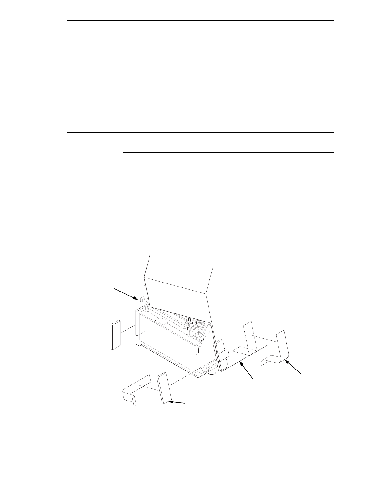
183380a
Tape Strips (2)
Foam Pads (2)
Media Cover
Frame
Printronix offers a wide range of ribbons specifically engineered to enhance
printing capabilities and to prevent premature printhead wear. Therefore, you
should use a Genuine Printronix Thermal Ribbon in your printer.
See “Genuine Printronix Thermal Transfer Ribbons” on page 344 for more
information.
Setting Up the Printer
Unpa cking t he Prin ter
The printer is shipped in a carton and protective bag. The top lid of the carton
has instructions for removing the internal packing material. Keep all packing
material in case repacking is required.
Ribbons
CAUTION
CAUTION
Avoid touching the electrical connectors to prevent electrostatic
discharge damage while setting up the printer. The discharge of
accumulated electrostatic energy can damage or destroy the printhead
or electronic components used in this device.
Do not place the printer on its backside during unpacking or handling,
because you may damage the printer interface connector.
1. Remove the tape strips from the media cover. Lift open the media cover.
2. Remove the tape securing the foam pad to the inside of the media cover.
3. Remove the foam pad between the front door and the frame.
17
Page 18
Chapter 1
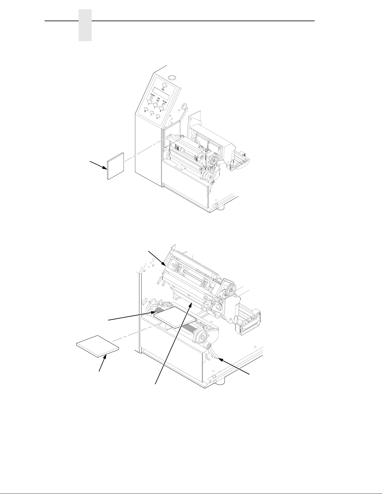
183381a
Foam
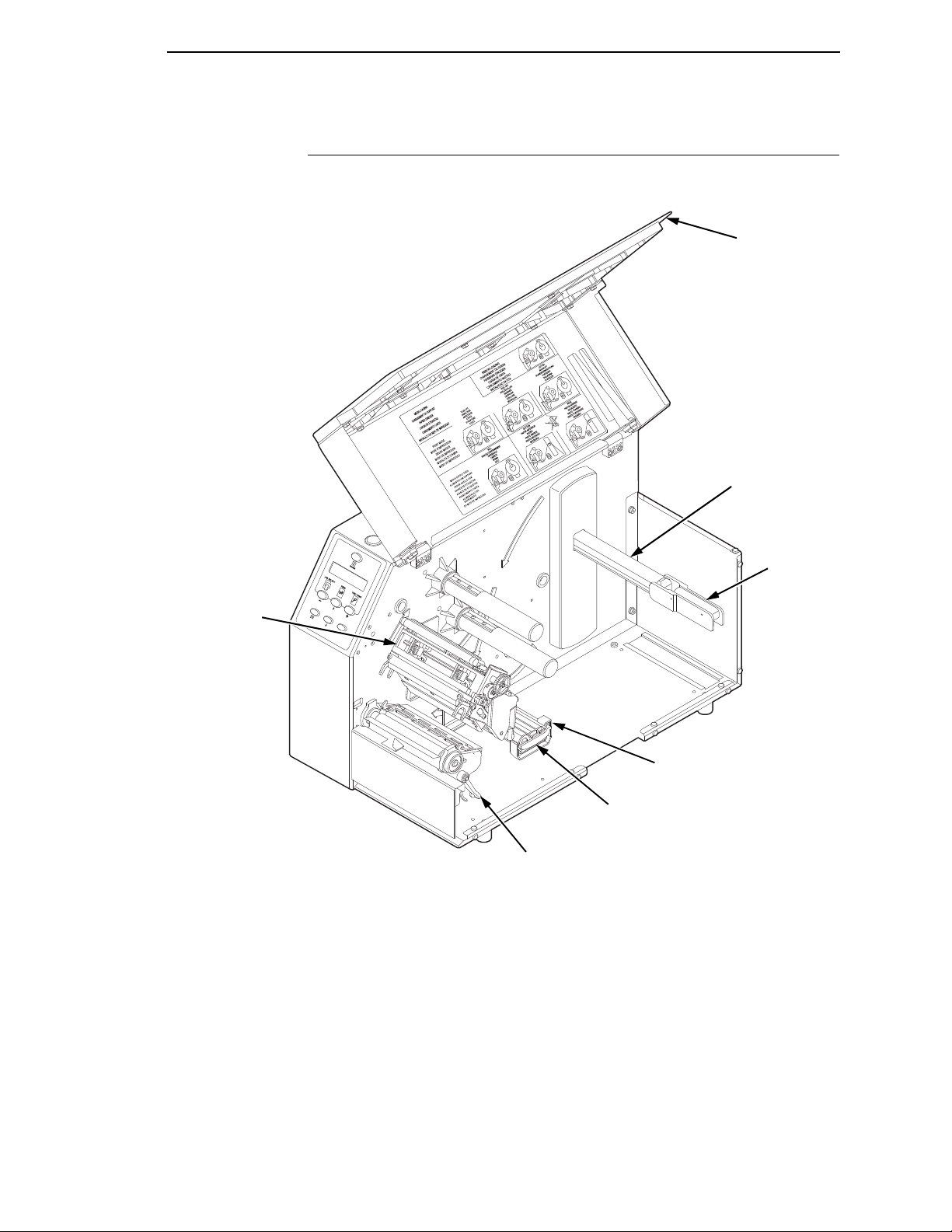
183382a
Foam Pad
Deck Lock
Lever
Pivoting Deck
Platen
Printhead
Setting Up the Printer
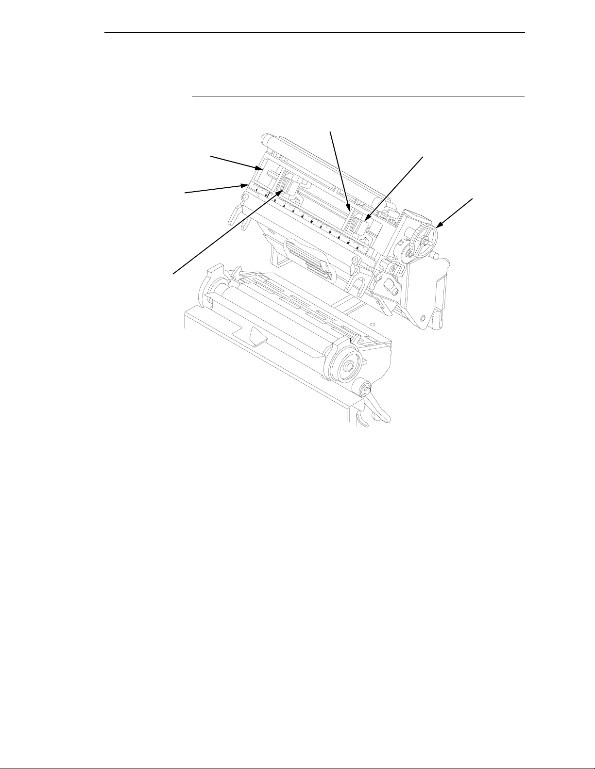
4. Remove the foam pad between the pivoting deck and the frame.
5. Open the pivoting deck by rotating the blue deck lock lever fully
clockwise.
6. Remove the foam pad from between the printhead and the platen (rubber
roller).
7. Close the pivoting deck and media cover.
18
Page 19

Installation
Installation
The following sections will guide you through the printer installation process.
1. Place the printer on a flat level surface that allows easy access to all sides
of the printer.
CAUTION
WARNING
CAUTION
Never operate the printer while it is resting on its side or upside down.
2. Check that the printer power switch is in the OFF (O) position.
Failure to properly ground the printer may result in electric shock to the
operator.
In compliance with international safety standards, this printer has been
equipped with a three-pronged power cord. When inserted in a correctly
wired power outlet, the ground conductor will ensure that the printer
chassis is at ground (earth) potential. Do not use adapter plugs or
remove the grounding prong from the cable plug. If an extension cord is
required, ensure that a three-wire cable with a prope rly grounded plug is
used.
3. Attach the AC power cord to the AC power receptacle in the back of the
printer.
Verify the required voltage on the printer’s model number label on the
rear of the printer.
4. Attach the AC power cord to a grounded (three prong) electrical outlet of
the proper voltage.
19
Page 20
Chapter 1
183383a
STATUS
DEBUG
PARA
LLEL
ETHERNET
RS232
GP
I0
USB
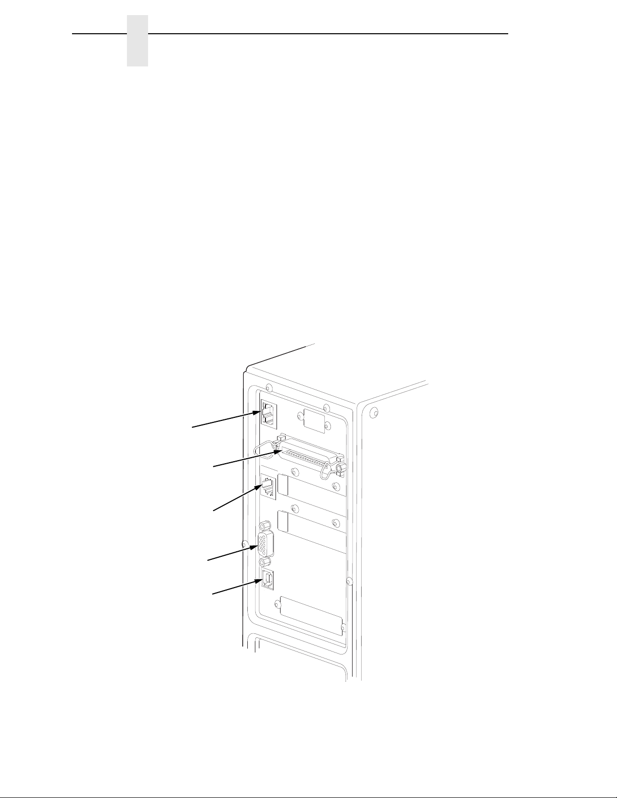
Parallel Interface
Serial Interface
Debug Interface
Standard Interface Panel
USB Connection
Ethernet Port
Setting Up the Printer
5. Attach Interface:
a. Parallel Interface
Attach a suitable parallel printer cable from the computer to the
Centronics/IEEE 1284 interface connector at the back of the printer.
Snap the bail locks to the Centronics connector to secure the
interface cable to the printer.
b. Serial Interface
Attach a suitable serial printer cable from the computer to the DB-9
RS-232 serial interface connector at the back of the printer. For
additional information on serial cable wiring, refer to
“Diagnostics and
Troubleshooting” on page 291.
NOTE: The printer supports simultaneous connection of the parallel, serial,
ethernet, and USB interfaces using the Auto Switching feature. Auto
Switching is described on
page 281.
20
Page 21
Installation
183384a
STATUS
DEBUG
PARA
LLEL
ETHERNET
RS232
GP
I0
USB
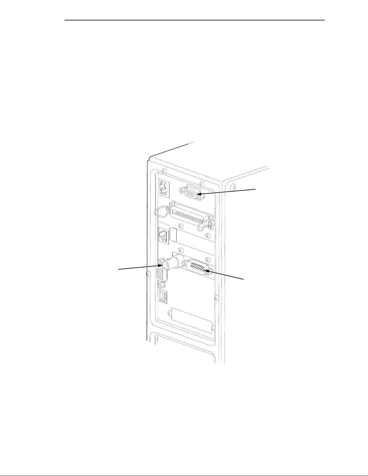
RS-422
Coax Connection
Coax/Twinax and RS-422 Panel
Twinax Connection
If your printer is equipped with the optional Coax/Twinax, and/or optional
RS-422, the rear I/O panel will appear as illustrated below.
NOTE: Autoswitching does not support simultaneous switching between
coax and twinax interfaces. However, autoswitching supports all
interfaces including coax or twinax. Auto Switching is described on
page 281.
21
Page 22
Chapter 1
183385a
STATUS
DEBUG
PARA
LLEL
RS232
GP
I0
USB
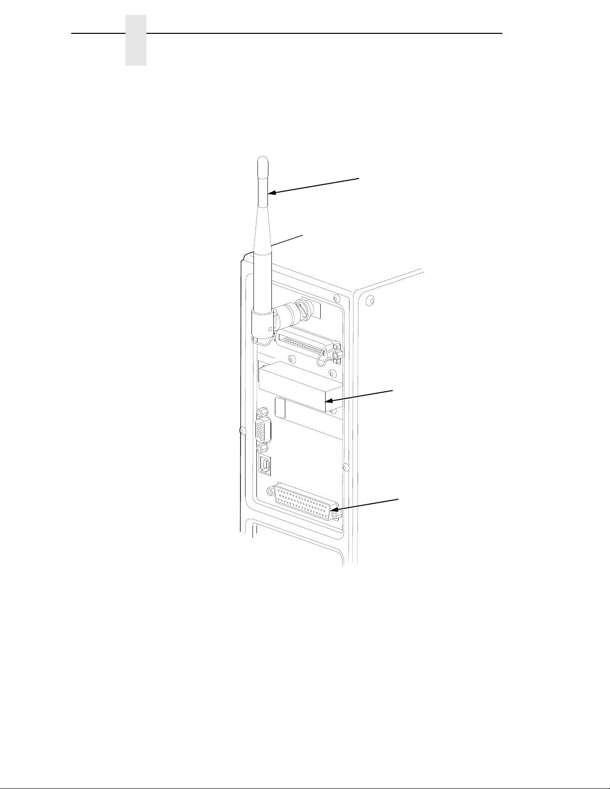
Wireless And GPIO Interface Panel
Wireless
Antenna
Wireless
Interface
GPIO
Connection
Setting Up the Printer
If your printer is equipped with the optional Wireless and Optional GPIO it
will appear as illustrated below.
c. Coax Connection
Attach a suitable coaxial cable from the computer to the coax
connector located in the I/O plate in the back of the printer.
d. Twinax Connection
22
Attach a suitable twinax cable from the computer to the twinax
connector located in the I/O plate in the back of the printer.
e. NIC Connection
Insert a suitable NIC cable from your hub or switch to the NIC
connector located in the I/O panel in the rear of your printer.
Page 23
2
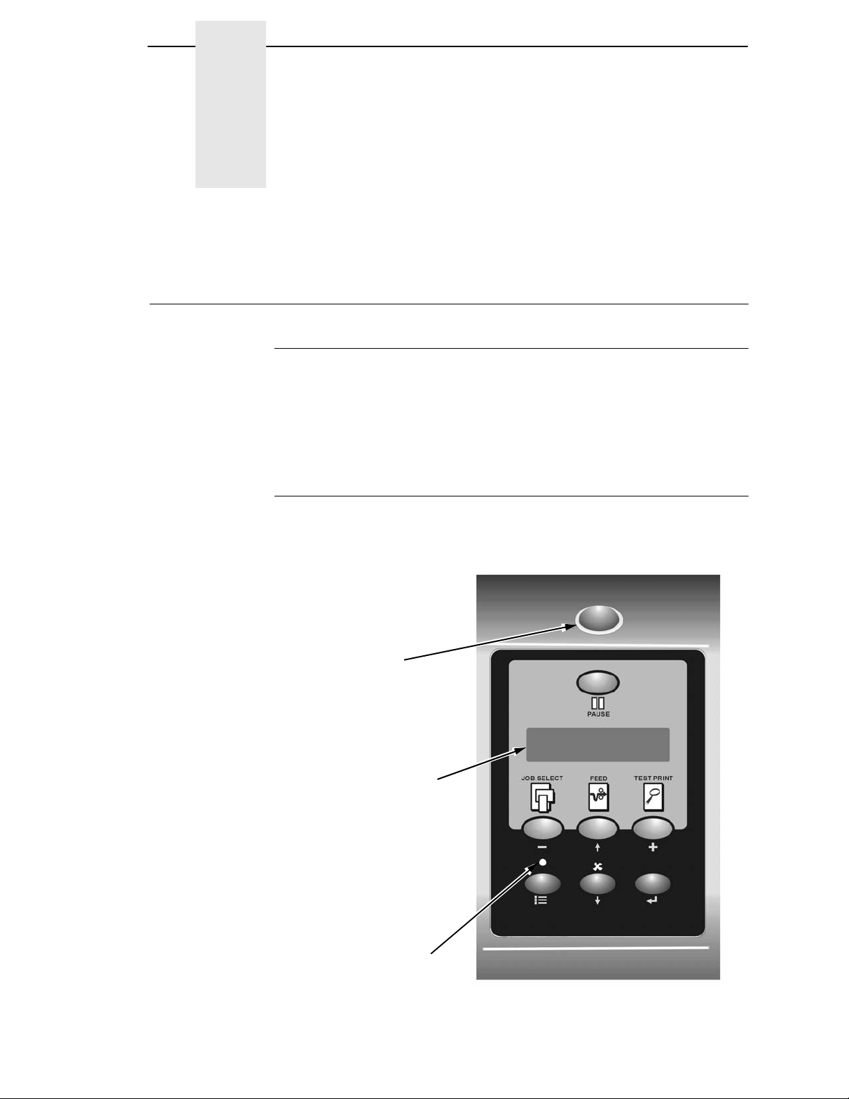
OFFLINE
Liquid Crystal
Display (LCD)
Online Status
Indicator
Job In Process
Indicator
Operation
Controls and Indicators
Power Switch
The power switch is located on the bottom back panel of the printer. To apply
power, place the switch in the | (ON) position. When you first power on the
printer, a series of initialization messages will appear on the Liquid Crystal
Display (LCD) on the control panel.
To remove power, place the power switch in the O (OFF) position.
Control Panel
The control panel is located on the front of the printer and includes an LCD,
indicators, and control keys (buttons). These are described in the following
tables. (Also refer to Chapter
3.)
23
Page 24

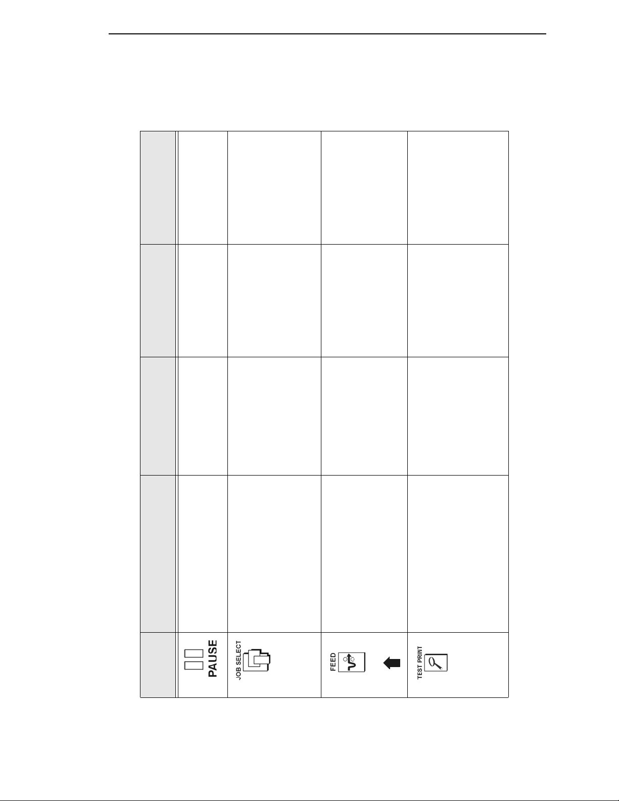
Indicator Description
Function in
Online Mode
Function in
Offline Mode
Function in
Menu Mode
Online Status Indicates when the
printer is online, offline,
or when there is a fault
condition.
Stays lit when the
printer is online, ready
to print, and accept
data from the host.
Flashes during a fault
condition.
Off when the printer is
offline.
Flashes during a fault
condition.
Off.
Flashes during a fault
condition.
Liquid Crystal
Display (LCD)
A backlighted liquid
crystal display with two
rows of 16 characters
each.
Displays “ONLINE,” the
interface type, and
emulation in use.
During a fault condition,
displays the specific
fault message and the
corrective action.
Displays “OFFLINE.”
During a fault
condition, displays the
specific fault message
and the corrective
action.
Displays main menu,
submenu, or option.
During a fault
condition, displays the
specific fault message
and the corrective
action.
Job In Process Indicates when the
printer is receiving or
processing data.
Flashes when receiving
data. Stays lit when data has
been processed and is
waiting to be printed.
Off when no data is
being received or when
no data remains in the
buffer.
Flashes when
receiving data. Stays lit when data has
been processed and is
waiting to be printed.
Off when no data is
being received or when
no data remains in the
buffer.
None
Chapter 2
Controls and Indicators
Sta tus and Display Indicators
24
Page 25
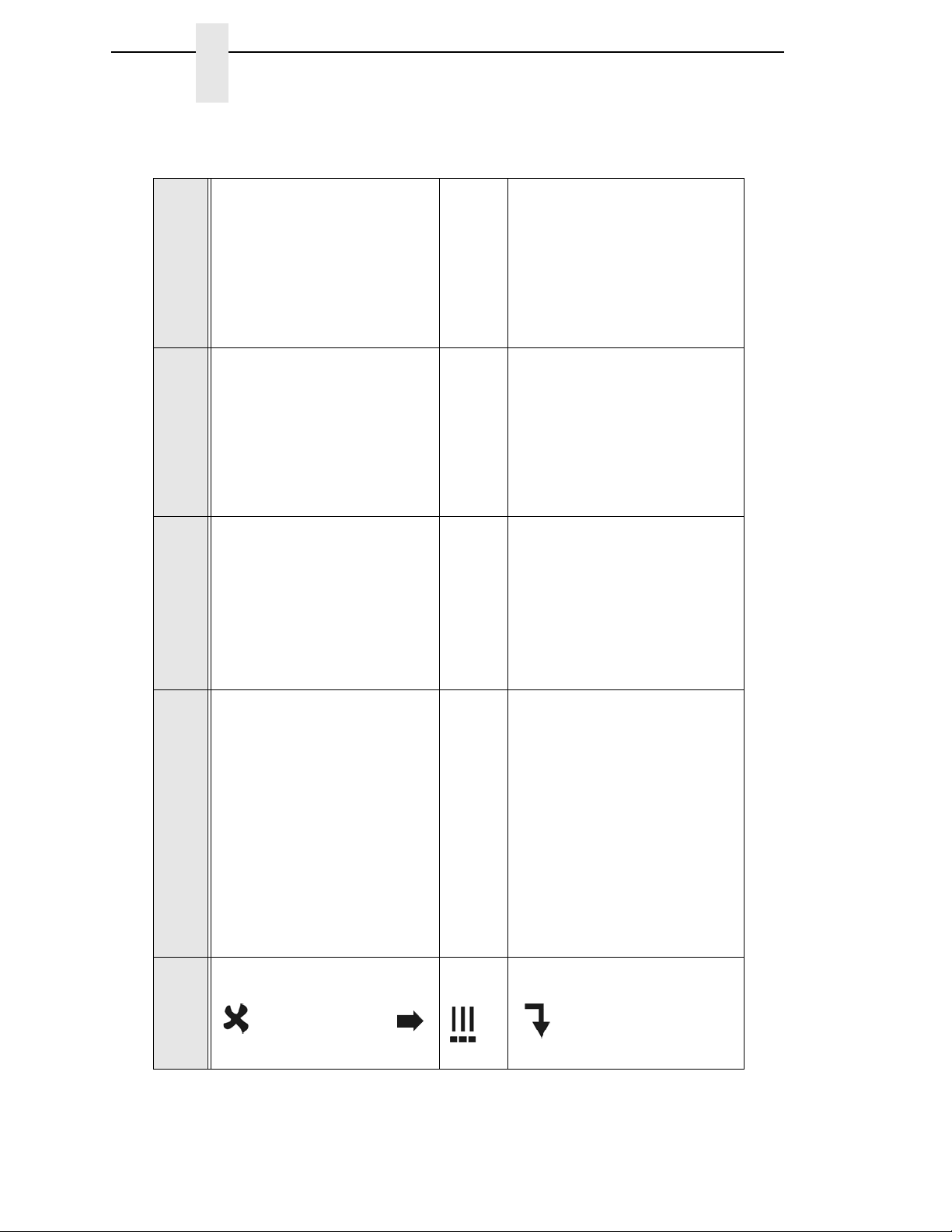
Button Description
Function in
Online Mode
Function in
Offline Mode
Function in
Menu Mode
PAUSE Key
Toggles the printer between
Online and Offline Modes.
Sets printer to Offline
Mode.
Sets printer to Online
Mode.
Sets printer to Offline
Mode.
JOB SELECT Key None Displays the name
and number of the last
loaded configuration
and allows you to load
the factory and/or
pre-stored printer
configurations.
Scrolls left through
main menus.
Decrements option
values within
submenus.
-
DECREMENT Key in
Menu Mode
FEED Key
UP Key in Menu Mode
Advances the media
one label length.
Advances the media
one label length.
Scrolls the current
menu selection one
level up.
TEST PRINT Key
Pressing the ↵ (ENTER) key
with a Diagnostic Test displayed
initiates the test. Pressing ↵
again terminates the test.
None Selects the Printer
Tests menu and
scrolls through the
Test Print patterns.
See “Printer Tests” on
page 226.
Scrolls right through
main menus.
Increments option
values within
submenus.
+
INCREMENT Key in
Menu Mode
Control Panel
Control Panel Keys
25
Page 26
Button Description
Function in
Online Mode
Function in
Offline Mode
Function in
Menu Mode
CANCEL Key
When the CANCEL key is enabled,
pressing it will clear all data in the
printer buffer and prevent printing of
that data.
Note: The factory default = Disable.
However, when the Coax/Twinax
Interface option is installed, the
factory default = Enable.
DOWN Key in Menu Mode
None Clears all data in the
printer data buffer
when enabled.
Scrolls the current
menu selection one
level down.
MENU Key Takes the printer
Offline and selects the
Menu Mode.
Selects the Menu
Mode.
Scrolls between main
menu selections.
ENTER Key
Pressing the ↵ (ENTER) key in
Menu Mode selects the displayed
option or value. An asterisk then
appears next to the option or value
indicating it has been selected.
Note: If the ENTER key is locked,
“ENTER SWITCH LOCKED”
displays on the LCD for one second.
Press the (DOWN) and
↵ (ENTER) keys at the same time to
unlock the ENTER key.
None None Selects the current
menu value and
displays an asterisk
(*) next to the value.
Chapter 2
Controls and Indicators
Control Panel Keys (co nt.)
26
Page 27

Powering On the Printer
Powering On the Printer
When you power on the printer, it executes a self-test. During the self-test, the
LCD momentarily displays the DPI resolution (203 or 300 DPI) of the installed
printhead. The default power-on state is online. Once the printer has
successfully initialized, the ONLINE status indicator light illuminates, and the
LCD indicates the communication interface selected and the emulation
selected.
If there is a fault during the self-test, the ONLINE status indicator flashes, and
a fault message appears on the display. The alarm may also sound, if
configured to do so.
Operating Modes
The current operating mode can be selected through the control panel keys or
can result from routine operations such as powering on the printer.
Online: In online mode, the printer can receive and print data sent from the
host. Pressing the PAUSE key toggles the printer between the online and
offline modes. The ONLINE status indicator is lit in online mode.
Offline: In offline mode, you can perform operator functions such as loading
media or changing ribbon. Pressing the PAUSE key toggles the printer from
offline to online mode. The ONLINE status indicator is not illuminated in offline
mode.
Menu: Pressing the MENU key takes the printer offline and into Menu mode.
In this mode, you can navigate through all configuration and status menus
and change the printer configuration.
Fault: In fault mode, a fault condition exists that must be cleared before
printing can continue. The ONLINE status indicator flashes, the alarm beeps
(if configured to do so), and a descriptive fault message displays.
Before normal printing can continue, the fault must be corrected, the message
cleared by pressing the PAUSE key, and the printer placed online.
Media Handling Modes
Before you load media, you must decide which media handling mode to use:
•
Continuous. Prints on the media and sends it out the front of the printer.
When the optional internal rewinder is installed, use “Continuous” for
Batch Rewind mode (see
•
Tear-Off Strip. Prints on the media and sends it out the front until the
print buffer is empty then positions the last label over the tear bar for
removal.
•
Tear-Off. After each label is printed, the printer positions the label over
the tear bar and waits for you to tear off the label before printing the next
label (on-demand printing). A “Remove Label” message will display to
remind you to remove the label before the next one can be printed.
page 43).
27
Page 28

Chapter 2
Loading Media and Ribbon
•
Peel-Off. When the optional internal rewinder is installed, the printer
prints and peels die-cut labels from the liner without user assistance. The
label liner is wound on the rewinder. The printer waits for you to take
away the label before printing the next one (on-demand printing). A
“Remove Label” message will display to remind you to remove the label
before the next one can be printed. For Label Peel-off information, see
page 48.
•
Cut. When the optional media cutter is installed, the printer automatically
cuts media after each label is printed or can cut the media after a
specified number of labels have been printed using a software cut
command.
Once you have decided on the mode, configure the printer. See Chapter 3 for
more information.
Loading Media and Ribbon
NOTE: This section describes the procedures for loading various types of
media and ribbon. You can also refer to instructions on the printer
itself, on a label on the inside of the media cover.
CAUTION
CAUTION
IMPORTANT
The term “media” in this manual refers to all the different kinds of paper, label,
or tag stock material that can be printed on by the printer. Your thermal printer
can print on continuous paper, adhesive backed labels, or non-adhesive tags
packaged in roll or fanfold form.
DO NOT TOUCH the printhead or the electronic components under the
printhead assembly. The discharge of electrostatic energy that
accumulates on the surface of the human body or other surfaces can
damage or destroy the printhead or electronic components used in this
device.
Do not close the pivoting deck without label stock installed between the
printhead and the platen, because debris on the platen may damage the
printhead.
Adhesive backed labels that DO NOT lay flat on the liner can jam the
printer. This can cause the label to peel off the liner. The exposed edges
can stick to the label guides and rollers inside the printer.
If you run out of labels while printing, do not turn off the printer while
reloading labels, because you can lose data.
28
Page 29
Loading Roll Media
183386a
Media Hanger
Media
Hanger
Guide
Media Width
Guide
Deck Lock Lever
Pivoting
Deck
Media Cover
Media Damper
Loading Roll Media
1. Open the media cover.
2. Slide the blue media hanger guide outward to the end of the media
hanger, and flip it up horizontally.
3. Open the pivoting deck by rotating the blue deck lock lever fully
clockwise.
4. Slide the blue media width guide close to the outside end of the media
damper.
29
Page 30
Chapter 2
183387a
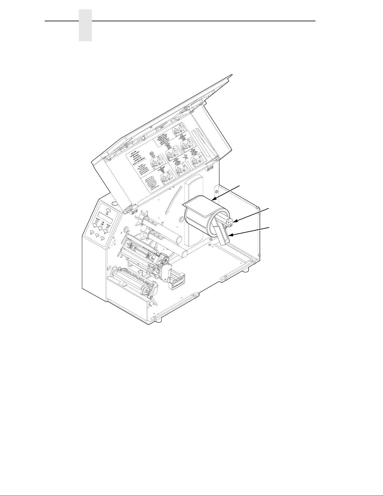
Media Roll
Media Hanger
Guide
Media Hanger
Loading Media and Ribbon
30
5. Slide a roll of media onto and towards the back of the media hanger. The
media feeds from the top of the roll and towards the front of the printer.
6. Place the media hanger guide under the media hanger and against the
lower part of the label core at a 45 degree angle (as shown). This position
provides the required tension for a new label roll and the desired drag for
a partial label roll.
Page 31

Loading Roll Media
183388a
Media Damper
Printhead
Platen (Rubber
Drive Roller)
Media and
Ribbon Loading
Instruction
Media
7. Thread the media under the media damper and then between the platen
(rubber drive roller) and the printhead.
You can also refer to the arrows on the printer frame or to the label inside
the media cover for media loading instructions.
31
Page 32

Chapter 2
183389a
Media Sensor
Handle
Media Guard
Lower Media
Sensor
Fixed Guide
Media Damper
Media Width
Guide
Loading Media and Ribbon
8. Verify that the left (inside) edge of the media is against the fixed guide on
the bottom of the media damper.
9. Push the blue media width guide in until it is flush with the outer edge of
the media.
10. Check the horizontal position of the lower media sensor (located under
the media guard), and refer to
“Positioning the Media Sensors” on
page 54.
32
Page 33

Loading Roll Media
183390a
Upper
Sensor
Visible Red Beam
Lower Sensor
Upper Sensor
Handle
Media Guard
Opening
183391a
Guide Notch
Media
(left edge)
11. Slide the upper sensor directly over the lower sensor.
12. Align the left (inside) edge of the media with the guide notch located on
the front edge of the tear bar.
33
Page 34

Chapter 2
183392a
Deck Lock Lever
Pivoting
Deck
Loading Media and Ribbon
IMPORTANT
13. Close the pivoting deck and rotate the deck lock lever fully
counterclockwise. This locks the pivoting deck and printhead assembly
into the printing position.
Ensure the pivoting deck is down and locked before attempting to
advance media or print. Failure to do so will cause the “PRINTHEAD UP”
fault message to display.
14. Verify that Print Mode in the printer configuration menu is set for the
media type installed (Direct or Transfer). The Print Mode submenu is
located in the QUICK SETUP menu. See
“Main Menu” on page 84 for
details.
15. Verify the printhead pressure is properly set. See “Printhead Pressure
Adjustment” on page 52.
16. Verify the pressure blocks are properly positioned. See “Printhead
Pressure Block Adjustments” on page 53.
17. Verify the Gap/Mark Sensor selection matches the type of media
installed. See
“Sensing Different Media Types” on page 59.
34
Page 35

Loading Roll Media
For direct thermal operation (no ribbon required):
•
If you have not run an Auto Calibrate, do so now. See “Running Auto
Calibrate” on page 60.
•
If you have already run an Auto Calibrate, complete the following
steps:
a. Close the media cover.
b. Press the FEED key once to verify that the media advances.
c. Press the PAUSE key to place the printer online.
For thermal transfer operation (which uses a ribbon):
Complete the ribbon loading procedure (see “Loading Ribbon” on
page 40).
35
Page 36

Chapter 2
183393a
Media
Hanger
Fanfold
Media
Media
Hanger
Guide
Fanfold
Tension
Arm
Deck Lock Lever
Pivoting
Deck
Media Cover
Bottom Panel
Opening
Loading Media and Ribbon
Loading Fanfold Media
CAUTION
36
1. Open the media cover.
2. Slide the media hanger guide outward to the end of the media hanger and
rotate it upward to a horizontal position to remove any roll media.
3. Place the fanfold media either behind or beneath the printer, depending
on the desired fanfold supply location. Insert the first few labels through
either the rear or bottom panel opening.
4. Place the media over the media hanger, flush against the back of the
printer.
5. Flip up the media hanger guide and slide it in against the outer edge of
the fanfold media.
6. Flip the fanfold tension arm down by pushing on it through the opening at
the top of the media hanger guide.
Do not allow the tension arm to snap down on the media hanger, this
could cause the tension arm to break. Instead, gradually lower the
tension arm onto the media hanger.
7. Open the pivoting deck by rotating the deck lock lever fully clockwise until
the deck swings upward.
Page 37

Loading Fanfold Media
183389a
Media Sensor
Handle
Media Guard
Lower Media
Sensor
Fixed Guide
Media Damper
Media Width
Guide
8. Slide the media width guide outward to the end of the media damper.
9. Thread the media under the media damper and then between the platen
(rubber drive roller) and the printhead. You can also refer to the arrows on
the printer frame or to the label inside the media cover for media loading
instructions.
Verify that the left (inside) edge of the media is against the fixed guide on
the bottom of the media damper.
10. Slide the media width guide inward against the outer edge of the media.
11. Check the horizontal position of the lower media sensor (located under
the media guard), and refer to
“Positioning the Media Sensors” on
page 54.
37
Page 38

Chapter 2
183391a
Guide Notch
Media
(left edge)
183392a
Deck Lock Lever
Pivoting
Deck
Loading Media and Ribbon
12. Align the left (inside) edge of the media with the guide notch located on
the front edge of the tear bar.
IMPORTANT
38
13. Close the pivoting deck and rotate the deck lock lever fully
counterclockwise. This locks the pivoting deck and printhead assembly
into the printing position.
Ensure the pivoting deck is down and locked before attempting to
advance media or print. Failure to do so will cause the “PRINTHEAD UP”
fault message to display.
14. Verify that Print Mode submenu is set for the media type installed (direct
or transfer). The Print Mode submenu is located in the QUICK SETUP
menu. See
“Main Menu” on page 84 for more information. Also, if thermal
transfer media is installed, see “Loading Ribbon” on page 40.
Page 39

Loading Fanfold Media
15. Verify the printhead pressure is properly set. See “Printhead Pressure
Adjustment” on page 52.
16. Verify the pressure blocks are properly positioned. See “Printhead
Pressure Block Adjustments” on page 53.
17. Verify the Gap/Mark Sensor selection matches the type of media
installed. See
For direct thermal operation (no ribbon required):
•
If you have not run an Auto Calibrate, do so now. See “Running Auto
Calibrate” on page 60.
•
If you have already run an Auto Calibrate, complete the following
steps:
a. Close the media cover.
b. Press the FEED key once to verify that the media advances.
c. Press the PAUSE key to place the printer online.
For thermal transfer operation (which uses a ribbon):
“Sensing Different Media Types” on page 59.
Complete the ribbon loading procedure (see “Loading Ribbon” on
page 40).
39
Page 40

Chapter 2
183394a
Ribbon Roll
Ribbon Supply
Spindle
Deck Lock
Lever
Pivoting
Deck
Ribbon
Take-Up Core
Ribbon
Take-up
Spindle
Loading Media and Ribbon
Loading Ribbon
Skip this section for 4 inch DT models or when using direct
thermal printing.
1. Install the ribbon take-up core on the ribbon take-up spindle.
NOTE: The first ribbon take-up core comes with the printer. Thereafter, use
the core from the old (used up) ribbon.
2. Slide the ribbon roll onto the ribbon supply spindle until it stops against
the spindle flange.
3. Open the pivoting deck by rotating the deck lock lever fully clockwise until
the deck swings upward.
40
Page 41

Loading Ribbon
183395 REV
183395a
Media
Printhead
Rear Ribbon Guide Roller
Ribbon
4. Thread the end of the ribbon under the rear ribbon guide roller, then
between the platen and the printhead.
You can also refer to the arrows on the printer frame or to the upper-right
corner of the label inside the media cover for ribbon loading instructions.
41
Page 42

Chapter 2
183396a
Ribbon
Take-up Spindle
Ribbon
Take-up Core
Media Cover
Media and Ribbon
Loading Instructions
Loading Media and Ribbon
IMPORTANT
Do not attach the ribbon to the ribbon take-up spindle without a
fiberboard take-up core installed.
5. Attach the ribbon to the ribbon take-up core on the ribbon take-up spindle
using the adhesive on the ribbon leader.
6. Manually rotate the spindle clockwise until the clear leader has passed
the printhead.
7. Close the pivoting deck and rotate the deck lock lever fully
counterclockwise.
8. Verify that Print Mode (in the QUICK SETUP menu) is set for Transfer.
See
“QUICK SETUP” on page 95 for more information.
9. If you have not run an Auto Calibrate with this media and ribbon, do so
now. See
“Running Auto Calibrate” on page 60.
10. Press the FEED key once to verify that the media and ribbon advance.
11. Press the PAUSE key to place the printer online.
12. Close the printer media cover if the rewinder is not needed.
42
Page 43

Using the Optional Internal Rewinder
183397a
Paper
Path
Groove
Hook
Front Door
The printer can be set up to rewind labels after they have been printed (Batch
Rewind Mode) or to automatically peel labels from their backing and dispense
them one at a time while rewinding the liner (Peel-Off Mode). Both modes
require an internal rewinder, which is available as a factory installed or a field
unit option.
Batch Rewind Mode
Batch Rewind allows you to automatically rewind printed labels into a roll
using the optional internal rewinder.
Configuring the Printer Menu
1. Set Media Handling to “Continuous” under the QUICK SETUP menu.
(See Chapter
2. Press the PAUSE key until “OFFLINE” displays.
3, “Configuring The Printer” for more information.)
Batch Rewind Mode
Installing the Paper Path
The paper path must be installed when using Batch Rewind mode.
To install the paper path:
1. Open the front door by pulling it upwards, then forward.
43
Page 44

Chapter 2
183398a
Rewinder
Rewinder
Release Lever
Using the Optional Internal Rewinder
2. The bottom of the plastic paper path is shaped like a hook and the top has
a groove:
a. Hook the bottom of the paper path under the bottom edge of the front
door.
b. Snap the groove on the paper path to the top edge of the front door.
3. Close the front door.
Loading Media
44
1. To load media, refer to “Loading Roll Media” on page 29 and complete
steps 1 through 10.
Page 45

Batch Rewind Mode
183399a
Rewinder Release Lever
Slot
Paper
Path
Media
183400a
Back Flange
Raised Ridge
Slot
Rewinder Release
Lever
Media or Liner
IMPORTANT
2. Thread the media over the front of the paper path and through the
opening under the front door toward the internal rewinder.
If you do not complete the following step, it will be extremely difficult to
remove the printed labels from the rewinder.
3. Turn the release lever on the rewinder counterclockwise and lock it in
place. This forms a raised ridge along the width of the rewinder.
4. Insert the leading edge of the media into the closest slot of the rewinder,
5. Hold the media edge in the slot and manually rotate the rewinder one full
and slide the media against the back flange.
revolution counterclockwise until the media is taut.
45
Page 46

Chapter 2
183401a
Deck Lock Lever
Media Cover
Using the Optional Internal Rewinder
IMPORTANT
6. Press down on both sides of the pivoting deck and rotate the deck lock
lever counterclockwise against its stop to place the printhead assembly
into the printing position.
7. Press the FEED key to advance the media to the next TOF (Top-of-Form)
position.
8. Press the PAUSE key until “ONLINE” displays.
9. Close the media cover.
The rewinder supports a maximum diameter of five inches of printed
labels. Exceeding this diameter can cause printed labels to rub on the
bottom pan.
46
Page 47

Removing Printed Media from the Rewinder
183401a
Printhead
Release
Lever
Rewinder
Batch Rewind Mode
1. Open the media cover.
2. Press the FEED key to advance the last printed label past the printhead,
and tear the liner from behind the last printed label.
3. Manually rewind the remaining printed labels onto the rewinder by turning
the rewinder counterclockwise.
4. Turn the release lever on the rewinder clockwise.
5. Slide the roll of printed labels off the rewinder.
47
Page 48

Chapter 2
183402a
Pivoting
Deck
Deck Lock
Lever
Bottom Roller
Tear Bar
Paper Path
Using the Optional Internal Rewinder
Label Peel-Off
You can set up the printer to automatically peel die-cut labels off their liner
(backing) and dispense them one at a time while rewinding the liner.
You can install the paper path to prevent long labels from accidentally
adhering to the front door assembly, but it is normally not needed when using
labels less than two inches long (see
Configuring the Printer Menu
1. Set Media Handling to “Peel-Off” under the QUICK SETUP menu. (See
Chapter
2. Press the PAUSE key until “OFFLINE” displays.
3, “Configuring The Printer” for more information.)
Loading Media
1. If you want to install the paper path to print long labels, do so now by
completing the steps listed in
2. Open the media cover and refer to the Label Peel-Off illustration on the
Ribbon and Media Loading instruction label on the inside of the cover.
“Installing the Paper Path” on page 43).
“Installing the Paper Path” on page 43.
48
3. Open the front door by pulling it upward, then forward.
4. Open the pivoting deck by rotating the deck lock lever clockwise until the
deck swings upward.
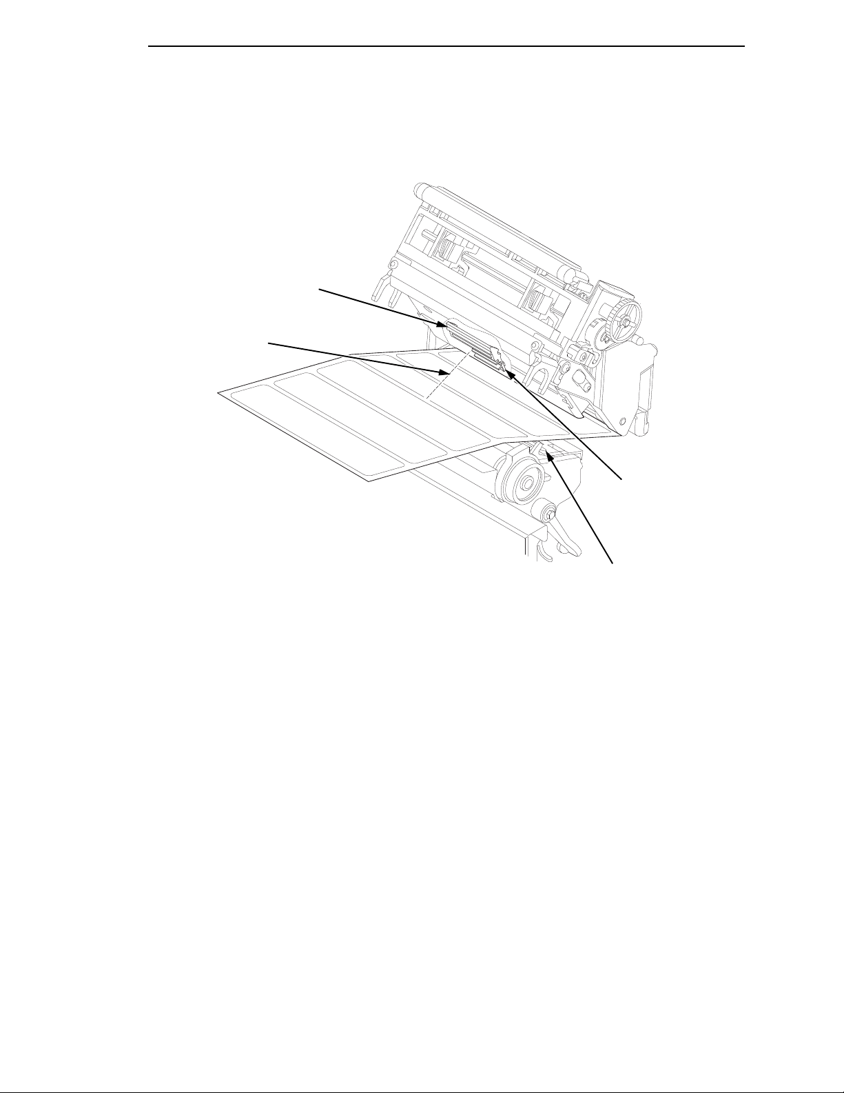
5. Thread the media (label and liner) over the tear bar and around the
bottom roller, then through the opening at the bottom of the front door and
into the printer.
Page 49

Label Peel-Off
183400a
Back Flange
Raised Ridge
Slot
Rewinder Release
Lever
Liner
183403a
IMPORTANT
If you do not complete the following step, it will be difficult to remove
the liner from the rewinder.
6. Turn the release lever on the rewinder counterclockwise and lock it in
place. This forms a raised ridge along the width of the rewinder.
7. Insert the leading edge of the media into the closest slot of the rewinder,
and slide the media against the back flange.
8. Hold the media in the slot and rotate the rewinder one full revolution
counterclockwise until the media is taut.
9. Remove labels from the liner so that behind the tear bar the liner is void of
labels for about 1.5 inches and below the tear bar for about 2 inches.
10. Close the front door.
11. Complete the media routing as shown above.
49
Page 50

Chapter 2
183404a
Deck Lock Lever
Media Cover
Using the Optional Internal Rewinder
IMPORTANT
12. Press down on both sides of the pivoting deck and rotate the deck lock
lever fully counterclockwise.
13. Press the FEED key. The label advances to the peel-off position, and
“Remove Label” displays on the LCD.
14. Manually remove the peeled label from the printer.
15. Press the PAUSE key until “ONLINE” displays.
16. Close the media cover.
The rewinder supports a maximum diameter of 5 inches of liner.
Exceeding this diameter can cause the liner to rub on the bottom pan.
The rewinder is designed to support the full amount of liner from a
standard 8 inch diameter media roll.
50
Page 51

Removing the Paper Path
183405a
Paper
Path
Groove
Hook
Front Door
Tear Bar
Removing Label Liner from the Rewinder
1. Open the media cover.
2. Open the front door.
3. Tear the liner at the tear bar.
4. Manually rewind the remaining liner onto the rewinder by turning the
rewinder counterclockwise.
5. Turn the release lever on the rewinder clockwise.
6. Slide the roll of label liner off the rewinder and discard.
Removing the Paper Path
Remove the paper path from the front door when using Tear-Off or Tear-Off
Strip media handling, because you will need to tear the label downward
against the tear bar.
1. Open the front door by pulling it upward, then forward.
2. Grasp the upper right corner of the paper path and pry it off of the top of
the front door.
3. After removing the paper path, close the front door.
4. Open the pivoting deck and load paper and ribbon normally (see “Loading
Media and Ribbon” on page 28).
51
Page 52

Chapter 2
183406a
Printhead Pressure
Adjustment Dial
Active Pressure
Setting
Printing Adjustments
Printing Adjustments
Printhead Pressu re Ad jus tme nt
52
Sometimes you will need to adjust printhead pressure because of variations in
media thickness and width. The printhead pressure adjustment dial is shown
above. The value shown at the bottom of the dial is the active setting.
In general, adjust printhead pressure to the lowest value which produces the
desired print quality. Die cut labels usually require a setting of 4, while heavy
stock requires a setting of 6 to max. The numbers on the printhead pressure
adjustment lever are relative only and do not indicate a specific printhead
pressure or media thickness. By following this procedure, you will minimize
printhead wear.
Page 53
Printhead Pressure Block Adjust ment s
183406a
Lead Screw
Knob
Right Pressure
Block Pointer
Pressure Block
Adjustment Scale
Left Pressure
Block
Left Pressure
Block Handle
Right Pressure Block
Printhead Pressure Bloc k Adjus tments
Printhead pressure block adjustments are used to obtain a uniform print
density across the width of the installed media under a variety of media and
ribbon conditions.
Left Pressure Block
Under normal printing conditions, the left block should be set with its handle
aligned with the bold mark on the pressure block adjustment scale. When
using media or ribbon widths less than one-third the printer’s maximum
printing width, you may need to manually slide the left pressure block further
to the left.
Right Pressure Block
The right pressure block should be positioned with its pointer (handle on
4 inch printer models) near the right edge of the media or ribbon in use. Turn
the lead screw knob clockwise to move the block right or counterclockwise to
move it left.
Check the pressure block positioning by printing the Grey test pattern:
1. Press the PAUSE key until “OFFLINE” appears on the LCD.
2. Press the TEST PRINT key until “Printer Tests/Grey” displays.
53
Page 54

Chapter 2
183407a
Vertical Gap and
Rounded Die-cut
Label Corners
Extraneous
Cut-out
Dark
Pre-printing
Position the
media sensors
in either of the
grey shaded
areas.
Printing Adjustments
3. Press the ↵ key to start the Grey test pattern. The pattern will start and
continue to print.
4. Press ↵ again to stop printing.
5. Check the test pattern. If necessary reposition the pressure blocks to
obtain a uniform print density across the media width. In most cases, only
the right pressure block may need to be adjusted.
6. Whenever you reposition a pressure block, run the Grey test pattern to
verify the print pattern is acceptable.
Positioning the Media Sensor s
Your printer is equipped with upper and lower media sensors that detect the
top-of-form position on media with label length indicators (gaps, notches,
holes, or black marks). These sensors also detect when a Paper Out
condition exists.
The media sensors should not be placed in the path of media features that
could cause false gap detection or paper out faults. Such features are dark
pre-printing, rounded die-cut label corners, vertical gaps associated with
side-by-side labels, and extraneous cut-outs, as shown below.
54
Page 55

Positioning the Media Sensors
183408a
Lower Sensor
Media Guard
Opening
Black Mark
(underside
of media)
Sensor Handle
Visible Red Beam
from Lower Sensor
Sensing Media with Horizontal Black Marks (Mark) or
Media with No Label Length Indicators (Disable)
Sensing Media with Horizontal B lack Ma rks
Position the lower media sensor for detecting horizontal black marks located
on the underside of media, and position the upper sensor above the lower
sensor to provide a consistent background.
1. Check the position of the sensor by looking through the long, narrow
2. Use the sensor handle to manually position the sensor to the center of the
3. Select “Mark” in the Gap/Mark Sensor submenu under the CALIBRATE
4. Perform an Auto Calibrate. See “Running Auto Calibrate” on page 60.
Sensing Media with No Label Length Indicators
1. When using media without label length indicators (no gaps, notches,
2. Select “Disable” in the Gap/Mark Sensor submenu under CALIBRATE
3. Perform an Auto Calibrate. See “Running Auto Calibrate” on page 60.
opening in the media guard. Use the visible red light emitting from the
lower sensor as a reference pointer.
black mark on the media.
CTRL menu. See
“Sensing Different Media Types” on page 59.
holes, or marks) or when you want to ignore all existing length indicators,
place the lower sensor in the center of the media so it can detect when a
Paper Out condition exists. Also set the upper sensor above it.
CTRL. See
“Sensing Different Media Types” on page 59.
55
Page 56

Chapter 2
183409a
Media Guard
Opening
Visible Red Beam
from Lower Sensor
Upper Sensor
Printing Adjustments
Sensing Media with Gaps, Notches, or Holes (Gap)
Position the lower media sensor for detecting gaps, notches, or holes in
media with a white background. If using direct thermal media, position the
upper sensor away from the lower sensor.
NOTE: The 4 inch SL/T5R media guard is divided into three open sensor
areas. Make sure the media sensor is placed in an open area.
1. Position the lower sensor directly under the center of the gap, notch, or
hole.
2. Check the position of the lower sensor by looking through the long,
narrow opening in the media guard. Use the visible red light emitting from
the lower sensor as a reference pointer.
3. Use the sensor handle to manually position the sensor to the center of the
gap, notch, or hole in the media.
4. Select “Gap” in the Gap/Mark Sensor submenu under the CALIBRATE
CTRL menu. See
5. Perform an Auto Calibrate. See “Running Auto Calibrate” on page 60.
“Sensing Different Media Types” on page 59.
56
Page 57
Positioning the Media Sensors
183410a
Upper Sensor
Handle
Media Guard
Opening
Visible Red Beam
Lower Sensor
Upper Sensor
Sensing Media with Dark Background Labels with Gap s
(Advanced Gap)
NOTE: Ribbon is not displayed in this illustration. The upper and lower
sensors are designed to function with or without ribbon installed.
The upper sensor and lower sensor are used together to detect liner gaps
between die cut labels that have a black or dark background on white or clear
liner.
1. Position the lower sensor directly under the center of the gap, and then
place the upper sensor directly over the lower sensor.
2. Check the position of the lower sensor by looking through the long,
narrow opening in the media guard. Use the visible red light emitting from
the lower sensor as a reference pointer.
3. Use the sensor handle to manually position the sensor to the center of the
gap in the media. Then use the handle on the upper sensor to position it
directly above the lower sensor.
NOTE: When using ribbon, you may need to slide the ribbon to one side to
adjust the upper sensor.
4. Select “Advanced Gap” in the Gap/Mark Sensor submenu under the
CALIBRATE CTRL menu. See
page 59.
5. Perform an Auto Calibrate. See “Running Auto Calibrate” on page 60.
“Sensing Different Media Types” on
57
Page 58

Chapter 2
183411a
Visible Red Beam
Lower Sensor
Upper Sensor
Handle
Media Guard
Opening
Upper Sensor
Black line
on underside
of media
Printing Adjustments
Sensing Dark Background Media with Notches or Holes
(Advanced Notch)
58
NOTE: Ribbon is not displayed in this illustration. The upper and lower
sensors are designed to function with or without ribbon installed.
The upper sensor and lower sensor are used together to detect notches or
holes in media with a black or dark underside. This combination can be found
on tag stock that has a black vertical line along one edge on the underside of
the label, interrupted by a notch or hole used as the label length indicator.
1. Position the lower sensor directly under the center of the notch or hole,
and then place the upper sensor directly over the lower sensor.
2. Check the position of the lower sensor by looking through the long,
narrow opening in the media guard. Use the visible red light emitting from
the lower sensor as a reference pointer.
3. Use the sensor handle to manually position the sensor to the center of the
notch or hole in the media. Then use the handle on the upper sensor to
position it directly above the lower sensor.
NOTE: When using ribbon, you may need to slide the ribbon to one side to
adjust the upper sensor.
4. Select “Advanced Notch” in the Gap/Mark Sensor submenu under the
CALIBRATE CTRL menu. See
“Sensing Different Media Types” on
page 59.
5. Perform an Auto Calibrate. See “Running Auto Calibrate” on page 60.
Page 59

Sensing Different Media Types
.
.
.
.
.
.
Sensing Different Media Types
The printer’s media sensors can detect the different types of label length
indicators on a large variety of media types. This is accomplished by selecting
the correct sensor option: Gap, Mark, Advanced Gap, Advanced Notch, or
Disable under Gap/Mark Sensor in the CALIBRATE CTRL menu.
page 335 illustrates the different media types and label length indicators used
on them.
1. Press to place the printer in Menu mode.
2. Press ↓ and ↵ together until “ENTER SWITCH UNLOCKED” displays.
3. Press until “CALIBRATE CTRL” displays.
4. Press ↓ until “Gap/Mark Sensor/Advanced Gap*” (the currently enabled)
option displays.
5. Press + or - until the option that matches the type of label length
indicators on the installed media displays:
•
Mark. Select when using media that has horizontal black marks
located on the underside of the label liner or tag stock.
Figure 9 on
•
Gap. Select when using media with a liner space between die-cut
labels or when using tag stock with notches or holes as label length
indicators on white background media.
•
Advanced Gap. Select when using media that has liner gaps
between die cut labels with black background.
•
Advanced Notch. Select when using media with notches or holes
that interrupt a black vertical line on the underside of the media.
•
Disable. Select when using media with no label length indicators (no
gaps, notches, holes, or black marks) or when you want the printer to
ignore all existing label length indicators on the installed media.
NOTE: When you select Disable, the length of each label is based on the
Label Length value entered in the QUICK SETUP menu or the value
sent via host software.
NOTE: If the printer detects a false PAPER OUT message when you change
from Advanced Gap or Advanced Notch to Gap or Mark sensing or
vice-versa, press the PAUSE key and run Auto Calibrate.
6. Press
7. Press PAUSE until “OFFLINE” appears on the LCD.
8. Review “Calibrating the Media Sensors” on page 60.
↵
to enable the displayed option. An asterisk (*) appears next to
the selection.
9. Perform the Auto Calibrate procedure on page 60.
59
Page 60

Chapter 2
Printing Adjustments
Calibrating the Media Sen sor s
Due to manufacturing differences in media and ribbon, the media sensors
may have difficulty differentiating between the label and the liner or the label
and the black mark. When this occurs, the printer may intermittently skip a
label or display a fault message such as “GAP NOT DETECTED/See Manual”
or “PAPER OUT/Load Paper.”
Media sensor sensitivity and reliability can be improved by changing the
Gap/Mark Threshold and/or Paper Out Threshold values. You can change
these values automatically by performing the Auto Calibrate or Manual
Calibrate procedure in the CALIBRATE CTRL menu or change them manually
by entering your own Gap/Mark Threshold or Paper Out Threshold values.
(The changes take effect immediately within the current configuration menu.)
Auto or Manual Calibrate is completed successfully when the displayed
Sensed Distance value correctly matches that of the installed media. When
Gap is selected, the Sensed Distance should match the length from the
trailing edge of one gap to the trailing edge of the next gap (or one label + one
gap). When Mark is selected, the Sensed Distance should match the length
from the leading edge of one black mark to the leading edge of the next black
mark.
When you have completed Auto or Manual Calibrate, you can verify the new
values are correct by pressing the FEED key several times. Each time you
press FEED, media advances one label and stops at the correct Top-of-Form
position of the next label.
Once you confirm the correct values, save them to the desired configuration
menu before powering off the printer. See
page 76.
“Saving a Configuration” on
Running Auto Calibrate
You can initiate Auto Calibrate via the TEST PRINT key (described in detail
below) or via the CALIBRATE CTRL or DIAGNOSTIC menus in Menu mode.
NOTE: Verify that the Gap/Mark Sensor option (Gap, Mark, Advanced Gap,
Advanced Notch, or Disable) matches the installed media. See
“Sensing Different Media Types” on page 59.
Check that the media sensors are horizontally positioned to permit
sensing of the label length indicators. See
Sensors” on page 54.
Make sure the Label Length value entered in the QUICK SETUP
menu matches the physical length of the installed media. Entering the
correct length forces the printer to advance media far enough during
calibrate for long labels (so actual gaps, notches, and marks can be
detected) and reduce the amount of media advanced for short labels.
If you try to do an Auto Calibrate when Peel-Off Media Handling is
enabled, the LCD will display “CANNOT CALIBRATE/Disable PeelOff.” Before you can do an Auto Calibrate, you must select another
media handling mode.
“Positioning the Media
60
Page 61

Running Auto Calibrate
1. Press the PAUSE key until “OFFLINE” appears on the LCD.
2. Press ↓ and ↵ together until “ENTER SWITCH UNLOCKED” displays.
3. Press the TEST PRINT key until “Printer Tests/Auto Calibrate” displays.
4. Press ↵. Media advances until it can accurately detect the label length
indicators and then stops at the Top-of-Form position. The Sensed
Distance value will then display for one second.
5. Auto Calibrate is successful when the Sensed Distance value correctly
matches that of the installed media:
•
Gap/Mark Sensor = Gap, Advanced Gap, or Advanced Notch:
The Sensed Distance value is the physical length of one label plus
the length of one gap, notch, or hole.
•
Gap/Mark Sensor = Mark: The Sensed Distance value is the
physical distance from the leading edge of one black mark to the
leading edge of the next.
•
Gap/Mark Sensor = Disable: Not applicable. If Gap/Mark Sensor is
set to Disable, the Sensed Distance value will not be updated.
If “GAP NOT DETECTED” displays, run Auto Calibrate again.
If Auto Calibrate continues to end with an incorrect Sensed Distance
value displayed or a fault message displayed, run Manual Calibrate as
described on
NOTE: The amount of media sampled during Auto Calibrate is based on the
length of a label and transitions detected, without error, between a
label and its label length indicators.
6. Press the PAUSE key until “OFFLINE” displays.
7. Press the FEED key several times. Each time you press FEED, the media
advances one label length and stops.
NOTE: After a form feed, the position of the leading edge of the next label
depends on the type of Media Handling mode selected under the
QUICK SETUP menu. Tear-Off and Tear-Off Strip Media Handling
will position the label edge at the tear bar, while Continuous will
position the label edge under the printhead.
8. Press the PAUSE key until “ONLINE” displays.
9. Once the Sensed Distance value is confirmed, you will need to save it to
the desired configuration menu before powering off the printer. See
“Saving a Configuration” on page 76.
page 66 or see Table 18 on page 309.
61
Page 62

Chapter 2
.
.
.
.
.
.
Printing Adjustments
Running Media Profile
The Media Profile printout shows the relationship of the Paper Out Threshold
and the Gap/Mark Threshold values, illustrates if and when each label length
indicator is detected, and shows the difference between the label length
indicators and the label. The profile printout (see
you set the thresholds for difficult media. This includes pre-printed labels,
labels with poor gap/media dynamic range, and smart labels that have
embedded RFID tags.
Once Media Profile is initiated, the printer will continue to advance media and
print the profile in landscape orientation until you press
NOTE: Verify the CALIBRATE CTRL menu Gap/Mark Sensor option (Gap,
Mark, Advanced Gap, Advanced Notch, or Disable) matches the
installed media. See
“Sensing Different Media Types” on page 59.
You will need a minimum installed label width of two inches to support
the Profile printout.
Ensure the media sensors are horizontally positioned to permit
sensing of the label length indicators. See
Sensors” on page 54.
Ensure the Print Mode option selected in the QUICK SETUP menu
matches the media installed. Select “Direct” for heat sensitive media
(no ribbon required) or “Transfer” for thermal transfer media (ribbon
required).
Figure 1 on page 63) helps
↵
to stop printing.
“Positioning the Media
1. Press to place the printer in Menu mode.
2. Press ↓ and ↵ together until “ENTER SWITCH UNLOCKED” displays.
3. Press until “CALIBRATE CTRL” displays.
4. Press ↓ until “Media Profile/Profile Print” displays and then press ↵. (The
printer will continue to print the profile until you press
↵
.)
The printer will advance media and continue to print a dynamic profile
image depicting the relationship of the label and any label length
indicators detected.
5. Press ↵. The printer will stop printing.
6. Press the PAUSE key until “OFFLINE” displays.
NOTE: The Gap/Mark and Paper Out Threshold values shown on the Profile
printout represent the last values determined from a successful Auto
or Manual Calibrate or the factory default values if no Auto or Manual
Calibrate was performed.
62
Page 63

Running Media Profile
183412a
1023
0767
0511
0255
0000
Paper Out (578)
Gap Mark (421)
FEED
183413a
1023
0767
0255
0000
Gap(209)
Detected Amplitude
of the Antenna
Detected Amplitude
of the Gap
Media Sens or
Position
Indicates Type of Gap/Mark
Sensing Selected
Paper Out(441)
0511
Figure 1. Media Profile Printout
Gap Sensing
This figure shows a Media Profile printout of a smart label where Gap/Mark
Sensor is set to Gap in the CALIBRATE CTRL menu.
In this example, the gap threshold value the printer selected (represented by
the Gap/Mark dotted line) is too close to the amplitude of the antenna pulse.
This may cause the printer to falsely use the antenna as the gap (top-of-form).
63
Page 64

Chapter 2
183414a
FEED
1023
0767
0511
0255
0000
Paper Out(441)
Gap(289)
Detected Amplitude
of the Antenna
Detected Amplitude
of the Gap
Media Sens or
Position
Indicates Type of Gap/Mark
Sensing Selected
Printing Adjustments
To avoid this problem, increase the Threshold Range value to 60% or 70% in
the CALIBRATE CTRL menu (the default is 50%), then run an Auto Calibrate
again (Cross-Ref to Auto Calibrate).
NOTE: Any changes to Threshold Range will not take effect until you run an
Auto Calibrate again.
This will raise the Gap/Mark threshold high enough so that the printer will not
falsely use the antenna as the gap (top-of-form).
64
Page 65
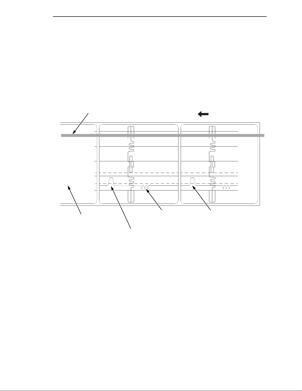
Running Media Profile
183415a
FEED
1023
0767
0511
0255
0000
Paper Out(301)
Adv. Gap(120)
Detected Amplitude
of the Antenna
Detected Amplitude
of the Gap
Media Sensor
Position
Indicates Type of Gap/Mark
Sensing Selected
Baseline (die cut label)
Advanced Gap Sensing
This figure shows a Media Profile printout of a smart label where Gap/Mark
Sensor is set to Advanced Gap in the CALIBRATE CTRL menu.
In this example, the gap threshold value the printer selected (represented by
the Gap/Mark dotted line) is too close to the baseline (die cut label). If there is
an increase in noise or the opacity of the liner or ribbon, the printer may
falsely use the noise as the gap (top-of-form).
To avoid this problem, increase the Threshold Range value to 60% in the
CALIBRATE CTRL menu (the default is 50%), then run an Auto Calibrate
again (Cross-ref to Auto Calibrate).
NOTE: Any changes to Threshold Range will not take effect until you run an
This will raise the Gap/Mark threshold high enough so that the printer will not
falsely use the antenna or noise as the gap (top-of-form).
Auto Calibrate again.
65
Page 66

Chapter 2
183416a
FEED
1023
0767
0511
0255
0000
Paper Out(301)
Gap(160)
Detected Amplitude
of the Antenna
Detected Amplitude
of the Gap
Media Sensor
Position
Indicates Type of Gap/Mark
Sensing Selected
.
.
.
.
.
.
Printing Adjustments
Running Manual Calibrate
Manual Calibrate should be performed only when the values derived from
Auto Calibrate fail to improve the media sensors’ ability to sense label length
indicators on the installed media. You must first enable “Admin User” in the
PRINTER CONTROL menu before accessing or initializing Manual Calibrate
in the CALIBRATE CTRL menu.
NOTE: Verify the Gap/Mark Sensor option (Gap, Mark, Advanced Gap,
Advanced Notch, or Disable) matches the installed media. See
“Sensing Different Media Types” on page 59.
Ensure the media sensors are horizontally positioned to permit
sensing of the label length indicators. See
Sensors” on page 54.
Ensure the Print Mode option selected in the QUICK SETUP menu
matches the media installed. Select “Direct” for heat sensitive media
(no ribbon required) or “Transfer” for thermal transfer media (ribbon
required).
If you try to do a Manual Calibrate when Peel-Off Media Handling is
enabled, the LCD will display, “CANNOT CALIBRATE/Disable PeelOff.” Before you can do a Manual Calibrate, you must select another
media handling mode.
1. Press to place the printer in Menu mode.
2. Press the ↓ and ↵ keys together until “ENTER SWITCH UNLOCKED”
displays.
3. Press until “PRINTER CONTROL” displays.
4. Press ↑ until “Admin User” displays, then press + until “Enable” displays.
“Positioning the Media
66
Page 67

Running Manual Calibrate
.
.
.
5. Press ↵ to select Enable. An asterisk (*) appears next to “Enable.”
6. Press until “CALIBRATE CTRL” displays.
7. Press ↓ until “Manual Calibrate/Run Calibrate” displays, then press the ↵.
8. Follow the instructions displayed on the LCD. Example: “REMOVE
RBN&MEDIA/Press Enter” indicates that you must open the pivoting deck
and remove the ribbon and media from under the printhead, close and
lock the pivoting deck, and press the
↵
key.
9. During the last step of Manual Calibrate, the printer will advance the
media and attempt to detect the label length indicators and stop at the
Top-of-Form position. The Sensed Distance value will then display for
one second. The calibrate is successful when the Sensed Distance value
correctly matches that of the installed media. If “CALIBRATION FAIL/See
Manual” displays, run Manual Calibrate again.
NOTE: The amount of media sampled during Manual Calibrate is based on
the length of a label and the transitions detected without error,
between a label and its label length indicators.
10. Press the PAUSE key until “OFFLINE” displays.
11. Press the FEED key several times. Each time you press FEED, the media
advances one label length and stops.
NOTE: After a form feed, the position of the leading edge of the next label
depends on the type of Media Handling mode selected under the
QUICK SETUP menu. Tear-Off and Tear-Off Strip Media Handling
positions the label edge at the tear bar, while Continuous positions
the label edge under the printhead.
12. Once the correct values are confirmed, save them to the desired
configuration menu before powering off the printer. See
“Saving a
Configuration” on page 76.
67
Page 68

Chapter 2
Cleaning
Cleaning
Depending on the media used, the printer may accumulate residues (media
dust, adhesives, etc.) as a by-product of normal printing. To maintain top
printing quality, you should remove these residues by cleaning the printer
periodically.
WARNING
IMPORTANT
CAUTION
Set the printer power switch to O (Off) prior to performing any cleaning
tasks. Leave the power cord connected to keep the printer grounded
and to reduce the risk of electrostatic damage.
When the printer is powered Off, menu settings that were changed and
not saved an any print data remaining in the print buffer will be lost. To
prevent the loss of recent menu changes, see
on page 76.
•
Do not wear rings or other metallic objects while cleaning any
interior area of the printer.
•
Use only the cleaning agents recommended in this section. Use of
other cleaners may damage the printer and void its warranty.
•
Do not spray or drip liquid cleaning solutions directly into the
printer. Apply the solution on a clean li n t-free cloth and then apply
the dampened cloth to the printer.
•
Do not use canned air in the interior of the printer as it can blow dust
and debris onto sensors and other critical components.
•
Only use a vacuum cleaner with a nozzle and hose that are
conductive and grounded to drain off static build up.
•
All reference in these procedures for use of isopropyl alcohol
requires that a 99% or greater isopropyl alcohol content be used to
reduce the risk of moisture corrosion to the printhead.
“Saving a Configuration”
68
Exterior Cleaning
Clean the exterior surfaces with a clean, lint-free cloth. If necessary, use a
mild detergent or desktop cleaning solution.
Interior Cleaning
Clean the interior of the printer by removing any dirt and lint with a vacuum
cleaner, as described above, or use a brush with soft non-metallic bristles.
Page 69

Cleaning the Printhead, Platen Roller, Media Sensors and Media Damper
Cleaning the Printhead, Platen Roller, Media Sensors
and Media Damper
NOTE: Even though the printhead, platen roller, media sensors and media
damper are individually listed in these cleaning procedures, debris
and adhesive on these components can ultimately travel to the
printhead area and therefore should be cleaned and examined each
time the printhead is cleaned and in the order shown.
Printhead Cleaning
As you use your printer, the printhead may become dirty with ribbon residue
and label adhesives which can result in poor print quality. Keeping the
printhead clean will help maintain its life.
•
Cleaning Agent - Clean the printhead using a Printhead Cleaning Pen,
Printronix PN 203502-002 or an Isopropyl Alcohol Wipe, Printronix PN
254945-901.
•
Schedule - Clean the printhead each time you install a new roll of ribbon
(thermal transfer print mode) or when you install a new roll or box of
media (direct thermal print mode).
WARNING
CAUTION
If you have just been printing, allow one minute for t he printhead to cool
down to avoid burns from accidental printhead contact.
•
Avoid electrostatic damage to the printhead by first making hand
contact with an unpainted part of the printer frame or by using an
anti-static wrist strap grounded to the printer frame.
•
Do not use hard, sharp or abrasive objects to remove residue from
the printhead.
•
Do not touch the heating element surface of the printhead with your
hands to avoid printhead corrosion. Any accidental skin contact
with the element surface should be immediately followed by a
thorough cleaning with a Printhead Cleaning Pen or an Isopropyl
Alcohol Wipe.
•
The heating element surface should be free from any condensation
to avoid corrosion.
1. Rotate the blue deck lock lever clockwise to open the pivoting deck and
remove the media and ribbon, if installed.
2. Clean the printhead by gently rubbing an Isopropyl Alcohol Wipe or the
felt tip of a Printhead Cleaning Pen across the printheads light brown
heating elements area. Allow the printhead to dry for one minute before
reloading ribbon or media.
NOTE: Even after a thorough cleaning with a Printhead Cleaning Pen or
Alcohol Wipe, you may still see printouts with voids or streaks. This
may be the result of baked-on ribbon resin that can be hard to remove
when normal cleaning cycles are not maintained. Try using a Thermal
Printer Cleaning Card or Sheet. When using a cleaning card or sheet,
follow the directions on the packaging.
Thermal printer cleaning cards and sheets are available on the
internet.
69
Page 70

Chapter 2
Cleaning
Platen Roller Cleaning
Label parts, media dust, and adhesive residue on the platen can degrade print
quality and cause voids in your label image.
•
Cleaning Agent - Use an isopropyl alcohol wipe or small amount of
isopropyl alcohol on a clean cloth to clean the platen roller.
•
Schedule - Clean the platen roller each time you clean the printhead.
3. Clean the platen roller by first removing any label parts from its surface by
hand. Then use an isopropyl alcohol wipe or clean cloth moistened with
isopropyl alcohol to remove any remaining paper dust, debris, or label
adhesive. The platen roller can be rotated forward by hand to access and
clean its entire surface area.
NOTE: Even though power is removed from the platen motor, some drag will
be felt as you rotate the platen.
4. Check the platen roller for razor cuts, nicks, and gouges that may cause
voids in the printed image. This type of damage usually requires platen
roller replacement.
CAUTION
Media Sensor Cleaning
The upper and lower media sensors should be cleaned to ensure reliable Top
of Form and Paper Out sensing.
Do not use isopropyl alcohol, solvents, or abrasive agents to clean the
lower media sensor as they can damage the sensors lens cover.
•
Cleaning Agent - Use a brush with soft non-metallic bristles or a vacuum
cleaner, described above, to remove paper dust.
NOTE: An Isopropyl Alcohol Wipe or Printhead Cleaning Pen can be used to
remove label adhesive from the upper sensor.
•
Schedule - Clean the media sensors each time you clean the printhead.
5. Brush away or vacuum any dust or debris from the upper and lower
sensor.
70
Page 71

Cleaning the Printhead, Platen Roller, Media Sensors and Media Damper
183417a
Pivoting
Deck
Printhead
Heating
Elements
Deck Lock
Lever
Printhead Cover/
Upper Media Sensor
Lower Media
Sensor
(visible with
red LED)
Platen Roller
Peel/Tear Door
A
183418a
A
Upper
Sensor
Print
Element
71
Page 72

Chapter 2
Cleaning
Media Damper Cleaning
The media damper and its media width guides (see page 32) can accumulate
parts of labels, adhesive and paper dust residue that can prevent the proper
guiding of labels.
•
Cleaning Agent - Use an isopropyl alcohol wipe or isopropyl alcohol on a
clean cloth.
•
Schedule - Clean the media damper and its width guides each time you
clean the printhead.
6. Clean the media damper by rotating it counterclockwise and remove any
label parts from its bottom surface. Then use an isopropyl alcohol wipe or
clean cloth moistened with isopropyl alcohol to remove all remaining
debris and adhesive from the damper and its inboard and outboard
guides.
IMPORTANT
WARNING
CAUTION
All adhesive must be completely removed to prevent future die cut
labels from being accidently peeled away from their liner.
Cutter Option Cleaning
The cutter requires only periodic cleaning.
Keep your fingers away from the cutter blades. They are sharp.
Perform the following procedure whenever too much dust or debris is visible.
1. Set the printer power switch to O (Off).
2. Rotate the deck lock lever fully clockwise until the deck swings upward.
3. Remove the cutter top cover by loosening the two captive thumbscrews.
4. Place the cutter in the down (open) position.
5. Use a vacuum or can of compressed air with a nozzle around the area of
the cutter blade to remove any dust or debris.
6. Use a cloth with a light amount of WD-40 oil to clean adhesive from the
cutter blade and upper or lower stainless steel cutter guides. Adhesive oil
must be cleaned from the blade and guides with a dry cloth to prevent
dust attraction.
Do not use isopropyl alcohol to clean the cutter blade – it dissolves oils
required for lubrication.
72
7. Place the cutter in the up (closed) position.
8. Install the cutter top cover and tighten the two captive thumbscrews.
9. Properly route the media through the printer and cutter.
10. Close the pivoting deck and rotate the deck lock lever fully
counterclockwise.
11. Set the printer power switch to | (On).
12. Test the printer cutting operation by pressing the TEST PRINT key and
selecting one of the test patterns to print.
Page 73

3
.
.
.
.
.
.
Overview
Configuring The Printer
This chapter provides information about:
•
Setting, saving, modifying, and printing configurations
•
Configuration menus
•
Downloading emulation and operating system software
Setting Printer Configuration Parameters
Configuration parameters are set from the control panel or are retrieved from
the printer’s memory. The parameters define how the printer will respond to
command and interface signals from the host computer.
The configuration menu structure consists of main menus and the options
applicable to each menu.
NOTE: Some configurations refer to printer options that may not be present
in your printer. If you select an option or feature that is not present, no
action will be performed by the printer or an “OPTION NOT
INSTALLED” message will display on the LCD.
Moving within the Configuration Menu
You can move through the configuration menus using the appropriate
navigation keys, as shown in
page 23 for more details on the function of the operator panel keys.)
You can select different options and save them as the power on default; you
can save up to 8 configurations with exception to the factory configuration.
The factory configuration menu can be altered, but not saved.
When the printer is online, the first line of the LCD displays “ONLINE” and the
second line lists the active interface port and type of emulation.
To configure the printer:
1. Press the key to enter the printer configuration menu system.
“MENU MODE/QUICK SETUP” displays on the LCD.
2. You can move through configuration main menus in two ways:
•
Press the key to move to the right.
•
Press the + key to move right or the − key to move left.
Figure 2. (See “Controls and Indicators” on
73
Page 74

Chapter 3
.
.
.
Step Press LCD Notes
1 OFFLINE
Overview
NOTE: In menus with numeric ranges of more than 50 numbers, hold down
the + or
increments of 5. To move in increments of 1 again, release your hold
on the + or
− key for more than 2 seconds to move through the range in
− key.
2
3 MENU MODE
4
5
6
↓
&
↵
↓
UNTIL
+
or
–
↵
Figure 2. Moving within the Configuration Menu
ENTER SWITCH
UNLOCKED
QUICK SETUP
Print Mode
Transfer*
Print Mode
Direct
Print Mode
Direct*
Selecting a Menu Option
To select an option, you need to press the ↵ key. By default, however, the
↵ key is “locked” when the printer is turned on to prevent accidental changes
to the configuration menu. If you press the ↵ key when the key is locked, the
message “ENTER SWITCH LOCKED” displays on the LCD for one second
and the value will not be selected.
To unlock the ↵ key, press the ↓ and ↵ keys simultaneously. This toggles the
ENTER/LOCK function.
Allows you to make
configuration
changes.
Enables the printer
configuration menu.
Cycles through the
choices.
Selects the Direct
transfer mode.
•
If this function is performed while the ↵ key is locked, the message
“ENTER SWITCH UNLOCKED” displays for one second, and the ↵ key
will be unlocked.
•
If this function is performed while the ↵ key is unlocked, the message
“ENTER SWITCH LOCKED” displays for one second, and the ↵ key will
be locked.
When you press the ↵ key (with the ↵ key unlocked), you select the value or
option that displays. An asterisk displays after the value you selected, and the
configuration is changed immediately.
74
Page 75

Changing Printer Settings
MENU MODE
QUICK SETUP
.
.
.
IMPORTANT
This change takes effect for all subsequent data and operations for the
printer as soon as the ↵ key is pressed and the asterisk (*) is displayed.
The configuration change(s) stay in effect only while the printer is
powered on. When the power is turned off, all current configurations will
be lost unless changes made to it are saved via the CONFIG. CONTROL
menu.
To save configuration information permanently or to select it as the power-up
default, see
“Saving a Configuration” on page 76.
Changing Printer Settings
You can change (or “configure”) printer settings, such as print speed or
emulations, through the control panel as follows:
1. Press the key until the following message displays:
2. Press the ↓ key to cycle through these options:
•
Print Intensity
•
Print Speed
•
Print Mode
•
Media Handling
•
Paper Feed Shift
•
Label Length
•
Label Width
•
Ver Image Shift
•
Hor Image Shift
•
Orientation
•
Gap/Mark Sensor
•
Auto Calibrate
•
Validator Function (if the validator option is installed. Refer to the
Online Data Validator User’s Manual.)
•
Active IGP Emul
•
xxx Diagnostics (xxx denotes Active IGP emulation)
•
Save Config.
•
Power-Up Config.
75
Page 76

Chapter 3
.
.
.
.
.
.
.
.
.
MENU MODE
CONFIG. CONTROL
Save Config.
1*
Overview
•
•
SMT: Status (if RFID is installed. Refer to the RFID Labeling
Reference manual.)
PAA: Status (if RFID is not installed)
IMPORTANT
3. When the desired submenu displays, press the
through the values or options.
4. Press the ↵ key to select a value. An asterisk (*) displays next to the
selected value or option.
5. If there are more submenu values or options you want to change, use the
,↑, ↓, +, and − keys to access the value and the ↵ key to select it. At
any time, you may press the key to return to the Main menu.
6. At any time, you may press the PAUSE key twice to exit the Configuration
menu and place the printer online. Once you have finished selecting all
your options, save your configuration.
If you do not save your configuration, all your new values will be lost
when you power off the printer.
+
or − key to scroll
Saving a Configuration
You can save up to eight different configurations to meet eight unique print job
requirements. These configurations are saved and stored in the printer and
are not lost when the printer is turned off.
NOTE: If the Protect Configs. option is enabled, the new configuration will not
be saved until the existing configuration is deleted.
Follow these steps to save a new configuration:
1. Press the key until the following message displays:
2. Press the ↓ key until the following message displays:
3. Press the + or − key to cycle through the options (1-8). Note that
“Factory” is not listed, because no changes made to the factory
configuration can be saved under Factory.
76
Page 77

Auto Save Configuration
Saving
Configuration
Save Config.
X*
CONFIG. EXISTS
Delete First
4. When the desired number displays, press the ↵ key to select it. The
following message displays briefly:
When processing is completed, the display shows:
NOTE: If the configuration number has been previously saved and Protect
Configs. = Enabled under CONFIG CONTROL, the following error
message displays:
If the above occurs, see “Modifying a Saved Configuration” on page 79,
step 4.
5. Print your configuration and store it in a safe place for future reference.
Refer to
“Printing a Configuration” on page 81.
Auto Save C onf igu rat ion
If you make any changes to the current configuration menu items, you will be
prompted to save the changes to “Config #” when you place the printer online.
“#” equals the next available unassigned configuration number. When
prompted, press one of the following keys:
•
Enter. Saves to Config 1 or the next available Config, and becomes the
Power-Up config.
NOTE: If all eight Configs are assigned, you will be prompted to select which
Config to overwrite.
•
Pause. Changes will be implemented but saved only temporarily until
deliberately saved as a new configuration or until you power off the
printer. All changes will be lost when you power off the printer.
77
Page 78

Chapter 3
.
.
.
MENU MODE
CONFIG. CONTROL
Power-Up Config.
1*
Power-Up Config.
X*
CONFIG. DOES NOT
EXIST/Save First
Overview
Specifying a Power-Up Configuration
You can specify any one of the nine configurations (1-8 or Factory) as the
power-up configuration:
1. Press the key until the following message displays:
2. Press the ↓ key until the following message displays:
3. Press the + or − key to cycle through the options (1-8 and Factory). When
the desired number displays, press the ↵ key to select it. The following
message displays:
NOTE: If the configuration number has not been saved previously, the
following error message displays:
If this error message displays, see “Saving a Configuration” on
page 76. Once you have saved a configuration, repeat the steps in
this procedure.
78
Page 79

Modifying a Saved Configuration
.
.
.
MENU MODE
CONFIG. CONTROL
Load Config.
Factory
Loading Saved
Configuration
Load Config.
X*
.
.
.
Modifying a Saved Configuration
You can change a saved configuration by rewriting over it. For example, you
can modify Config. 1, shown below. Suppose you want to keep all the settings
but you want to select the parallel Centronics interface instead of the IEEE
1284 interface.
1. Load the configuration to be changed (for example, Config. 1).
a. Press the key until the following message displays:
b. Press the ↓ key until the following message displays:
c. Press the + or − key to cycle through the options: Factory 1-8.
d. When the desired number displays, press the ↵ key to select it. The
following message displays:
Then, the following message displays when it is loaded:
2. Move through the menu and change all the desired values. (In this
example, press the
key until PARALLEL PORT displays. Press the ↓
key until Port Type/IEEE 1284 displays. Press the - key until Centronics
displays.)
3. Press the ↵ key to select each new value. An asterisk (*) displays.
79
Page 80

Chapter 3
Delete Config.
1*
Deleting
Configuration
Delete Config.
X*
Overview
4. Before saving the modified configuration, you must delete the original
configuration if the Protect Configs. option is enabled.
a. Press the ↑ or ↓ key until the following message displays:
b. Press the + or − key to cycle through the options (1-8). When the
desired number displays, press the ↵ key to select it. The following
message displays:
Then, the following displays when it is deleted:
5. Save the new configuration as described in the “Saving a Configuration”
on page 76. Make sure you select the same number (e.g., Config. 1)
when saving the modified configuration. The new configuration writes
over the existing one.
6. Print a copy of this newest configuration and store it in a safe place. Refer
to
“Printing a Configuration” on page 81.
80
Page 81

Printing a Configuration
.
.
.
MENU MODE
CONFIG. CONTROL
Print Config.
Current*
CONFIG. DOES NOT
EXIST/Save First
Printing a Configuration
We recommend that you print and store your configurations for future
reference. The printout provides a list of the parameters that were set when
you configured the printer.
To print a configuration:
1. Press the key until the following message displays:
2. Press the ↓ key until the following message displays:
3. Press the + or − key to cycle through the following printout options:
Current*
Factory
Power-Up
All
1-8 customized configurations
4. When the desired option displays, press the ↵ key. The printer prints the
specified configuration.
NOTE: If the configuration you want to print has not been saved, the
following message displays momentarily:
This message indicates that no configuration menu has been saved
under the configuration value you have selected and therefore cannot
be printed. You must either select another configuration to print or
load and then save a configuration to that configuration value first.
Loading A Saved Configuration
To use a different configuration:
1. Press the PAUSE key until OFFLINE displays.
2. Press the JOB SELECT key until the desired configuration displays.
3. Press ↵. Loading Saved/Configuration displays.
81
Page 82
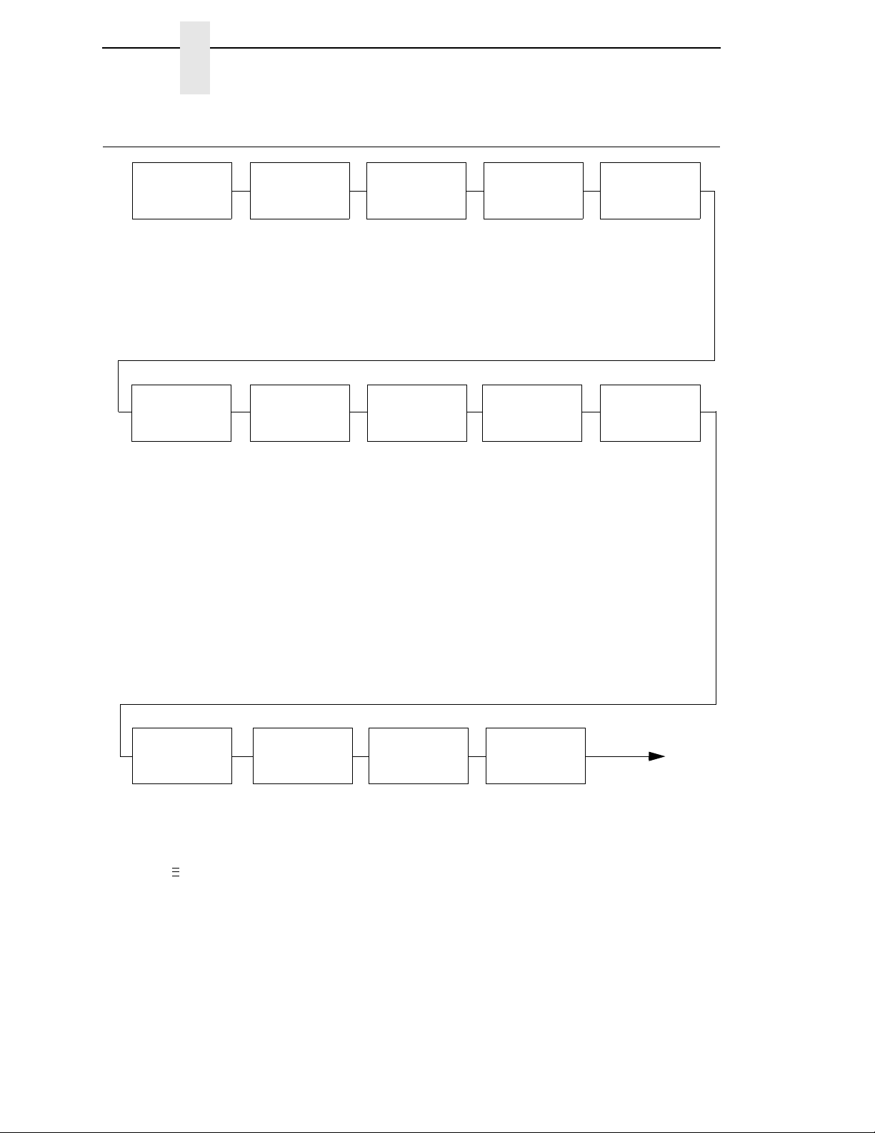
Chapter 3
QUICK
SETUP
Set the basic
menus needed to
configure the
printer.
VALIDATOR
2
Online data
validator setup
and status
reporting.
CONFIG.
CONTROL
Name, store, and
retrieve up to
eight custom
printer
configurations.
MEDIA
CONTROL
Control various
parameters
related to print
quality, media,
and ribbon.
CALIBRATE
CTRL
Select the correct
media sensing
for the media
type installed and
perform media
sensor
calibration.
PRINTER
CONTROL
Select the
desired Active
IGP emulation,
other emulations,
and various
printer operating
parameters.
Emulations
selected from the
PRINTER
CONTROL menu
appear here.
These
emulations relate
to graphics
languages,
particular
printers, and
optional host
interface
protocols.
DIAGNOSTICS
Select various
printer tests,
monitor and
record printer
performance.
PARALLEL
PORT
Select various
parallel port
related
parameters.
Press to select the next main menu.
Press ↓ or ↑ to move within each main menu.
.
.
.
ETHERNET
PORT
Selects various
ethernet port
related
parameters.
ETHERNET
ADDRESS
Sets the ethernet
address.
SELECTED
EMULATIONS
NOTES:
1
This menu appears only if an RFID encoder is installed.
See the RFID Labeling Reference Manual.
2
This menu appears only if a Validator is installed. See
the Online Data Validator User’s Manual.
SERIAL
PORT
Select various
serial port related
parameters.
RFID
CONTROL
1
RFID encoder
setup and status
reporting.
USB
PORT
Selects various
USB port related
parameters.
Menu Overview
Menu Overview
82
Page 83

Press to select the next main menu.
Press ↓ or ↑ to move within each main menu.
.
.
.
ETHERNET
PARAMETER
OPTIONAL
PORTS
Select optional
host interfaces.
OPTIONAL
FEATURES
Select optional
features, such as
DATE for Real
Time Clock.
PRINTER
MGMT
Select PNE port
type and port
number.
83
Page 84

Chapter 3
Save Config.
Load Config.
Print Config.
Delete Config.
Power-Up Config.
Protect Configs.
Name Config 1
Name Config 2
Name Config 3
Name Config 4
Name Config 5
Name Config 6
Name Config 7
Name Config 8
Reset Cfg Names
Auto Save
CONFIG.
CONTROL
(page 104)
NOTES:
Italicized items are available only when you enable Admin User
(under PRINTER CONTROL).
1
Gap/Mark Sensor and Paper Out Sensor work in conjunction, as
shown in Table 6 on page 127. If you change the Gap/Mark Sensor
or Paper Out Sensor, you must recalibrate the media.
2
This menu appears only if an RFID encoder is installed.
3
This menu appears only if a Validator is installed.
4
This menu will not appear on Direct Thermal only printers.
5
This menu appears only if RFID is installed and there is no CST
bundle in the Flash File System.
6
This menu appears only if RFID is not installed and there is a CST
bundle in the Flash File System.
7
xxx represents the emulation name selected in the Active IGP Emul
menu.
VALIDATOR
3
Press to select the next main menu.
Press ↓ or ↑ to move within each main menu.
Press + or
−
to cycle through each possible option or value.
.
.
.
Print Intensity
Print Speed
Print Mode
4
Media Handling
Paper Feed Shift
Label Length
Label Width
Ver Image Shift
Hor Image Shift
Orientation
Gap/Mark Sensor
1
Auto Calibrate
Validator Funct.
3
Active IGP Emul
xxx Diagnostics
7
Save Config.
Power-Up Config.
SMT: Status
5
PAA: Select Tool
6
QUICK
SETUP
(page 95)
Refer to the RFID
Labeling Reference
Manual.
RFID
CONTROL
2
Refer to the Online
Data Validator
User’s Manual
Main Menu
Main Menu
84
Page 85

SMT: Status
4
PAA: Select Tool
5
LP+ Emulation
CTHI Emulation
2
Active IGP Emul
xxx Diagnostics
7
Host Interface
Power Saver Time
Pwr Save Control
Display Language
Alarm
Power-up State
Ptx Setup SFCC
Cancel Key
Rcv. Status Port
Ret. Status Port
Compatibility
Del Char frm Fls
Ld Char from Fls
Save Char to Fls
Del Char frm RAM
Ld Char at PwrUp
Del Set frm Flsh
Ld Set from Flsh
Save Set to Flsh
Del Set from RAM
Ld Set at PwrUp
Overwrite Files
View File List
Delete Files
Flash Avail.
Optimize&Reboot
(continued in next column)
PRINTER
CONTROL
(page 135)
NOTES:
Italicized items are available only when Admin User is set to Enable (in the PRINTER
CONTROL menu).
1
Gap/Mark Sensor and Paper Out Sensor work in conjunction, as shown in Table 6 on page 127. If
you change the Gap/Mark Sensor or Paper Out Sensor, you must recalibrate the media.
2
Appears only if the CTHI option is installed.
3
This menu will not appear on Direct Thermal only printers.
4
This menu appears only if RFID is installed and there is no CST bundle in the Flash File System.
5
This menu appears only if RFID is not installed and there is a CST bundle in the Flash File System.
6
Menu available if CTHI option and IPDS option are not installed.
7
xxx represents the emulation name selected in the Active IGP Emul menu.
CALIBRATE
CTRL
(page 127)
Gap/Mark Sensor
1
Auto Calibrate
Media Profile
Sensed Distance
Gap/Mark Thresh
Paper Out Thresh
Paper Out Sensor
1
Manual Calibrate
Pwr Up Action
HeadClose Action
Online Auto-Cal
Gap Windowing
Gap Length
Cal in Peel Mode
Min Calib Delta
Use Label Length
Threshold Range
Print File List
Auto Locking
Set Lock Key
Ptx Setup Parse
PJL Enable
6
Page Mem Adjust
Max Font Buffer
Max Cache Memory
Max Cached Char
Standard Chars.
Bold Chars.
Extra Bold Char.
OCR-A Chars.
OCR-B Chars.
Tall Characters
Batch Counter
Feed Key Online
Admin User
Print Intensity
Print Speed
Print Mode
3
Media Handling
Paper Feed Shift
Label Length
Label Width
Ver Image Shift
Hor Image Shift
Orientation
Auto Map Select
Auto Label Width
Num Auto Labels
Slew Speed
Print Direction
Label Wait Time
Pre-Peel Mode
Pre-Peel Adjust
Lbl Missing Flt
Clip Page
Error Recover
Ribbon Width
3
Display Ribbon
3
Ribbon Low
3
Rbn Takeup Full
3
Units
Set Label Length
Peel Present
Peel-Off Mode
Continuous Mode
TOF Detect Fault
Ticket Save Mode
TOF Adjust Mode
TOF Adjust
Ribbon Calibrate
3
Reverse Speed
Vertical DPI Adj
MEDIA
CONTROL
(page 107)
85
Page 86

Chapter 3
NOTES:
Italicized items are available only when Admin User is set to Enable (in the PRINTER CONTROL menu).
1
Gap/Mark Sensor and Paper Out Sensor work in conjunction, as shown in Table 6 on page 127. If you
change the Gap/Mark Sensor or Paper Out Sensor, you must recalibrate the media.
2
Appears only if the CTHI option is installed.
3
Appears only if selected as the Port Type (under C/T PORT).
4
Appears only if the CTHI emulation (under PRINTER CONTROL) is set to Simp Prot Conv.
5
Appears only if the “User Defined” option in the “Lead-in Chars” menu is selected.
6
Does not appear if IPDS is installed.
7
Does not appear if CTHI emulation (under Printer Control) is set to Simp Prot Conv..
SPC TWINAX
SETUP
2, 3, 4
(page 159)
SPC Type
SFCC Char
User-Defined St1
5
User-Defined St2
5
User-Defined Stp
5
SPC Char Set
Translation Tbl
Buffer Print
TWINAX
SETUP
2, 3, 7
(page 156)
Primary Sets
Translation Tbl
6
Buffer Print
Twinax Type
Active Char Set
Secondary Sets
5225 World Trade
Cancel IGP/DCU
Lead-in Chars
User-Defined St1
5
User-Defined St2
5
User-Defined Stp
5
Alt. Set 80-9F
Graphic Chek Err
Graphic Chek Cod
LAC Option
LAC Approx.
Set Text Orientn
Host Override
Format Control
Max. Print Width
SPC COAX
SETUP
2, 3, 4
(page 158)
SPC Type
Logical Buf Size
Intervention Req
Buffer Print
Translation Tbl
PA1
PA2
Buffer Reprint
Null Handling
SPC Null Supp
SPC Space Supp
SFCC Char
User-Defined St1
5
User-Defined St2
5
User-Defined Stp
5
NL At MPP + 1
COAX
SETUP
2, 3, 7
(page 153)
Primary Sets
Translation Tbl
PA1
PA2
Buffer Reprint
Buffer Print
Coax Type
Active Char Set
Secondary Sets
Early Print Cmpl
SCS Buffer Cntrl
Alt. Set 80-9F
Intervention Req
CR At MPP + 1
NL At MPP + 1
Position Aft FF
Last Char = FF
Null Suppression
FF Validity
Auto Skip At End
FF After J ob
CR, EM, & NL
Translate Table
Host Override
Format Control
Cancel IGP/DCU
Lead-in Chars
User-Defined St1
5
User-Defined St2
5
User-Defined Stp
5
Change Case
Set Text Orientn
Max. Print Width
Main Menu
86
Page 87

NOTES:
Italicized items are available only when Admin User is set to Enable (in the PRINTER CONTROL menu).
1
Appears only if Active IGP Emul is set to PGL (in the Printer Control Menu).
2
Appears only if the IPDS emulation is installed, the correct security key is used, and either the CTHI
option is installed, the NIC is enabled, or the wireless NIC option is installed.
3
Appears only if the TN5250/3270 option is installed and either the NIC is enabled or the wireless NIC
option is installed.
4
Appears only if the “User Defined” option in the “Lead-in Chars” menu is selected.
PGL
SETUP
1
(page 168)
Character Group
Standard Sets
Select LPI
Define CR Code
Define LF Code
Autowrap
Auto Uppercase
Slash 0
Select SFCC
Host Form Length
Var Form Adjust
Var Form Type
Optimized Ratio
PI Slew Range
CR Edit
Skip Cmd Prefix
Ignore Text
Power on IGP/PGL
Ext Execute Copy
Al 00 Spaces
Select SO Char
Ignore Mode
Select Char
Do FF at TOF
IGP100 Compatbl.
Expanded Font
Scalable Size
Forms Handling
PGL Normal
UPC Descenders
I-2/5 Selection
C39 Compatbl.
User-Def Ratio
Lead PDF Dist
Trunc Dyn Data
Boundary Check
Repeat Form Opt
Preparser Port
Primary Sets
Translation Tbl
Active Char Set
Secondary Sets
Lead-in Chars
User-Defined St1
4
User-Defined St2
4
User-Defined Stp
4
Alt. Set 80-9F
Graphic Chek Err
Graphic Chek Cod
Set Text Orientn
Host Override
Format Control
Max. Print Width
5250 SETUP
3
(page 166)
IPDS SETUP
2
(page 160)
Default Font
Default Code Pag
Code Page Subset
Emulation
Early Print Comp
Host Form Length
Null Suppression
Page Rotation
VPA Check
Expanded Fonts
Resident Fonts
XOH-SMO Support
Hexdump Mode
Print IPDS Fonts
Primary Sets
Translation Tbl
Active Char Set
Secondary Sets
Early Print Cmpl
Alt. Set 80 -9F
Intervention Req
CR At MPP + 1
NL At MPP + 1
Position Aft FF
Last Char = FF
Null Suppression
FF Validity
Auto Skip At End
FF After Job
CR, EM, & NL
Host Override
Format Control
Lead-in Chars
User-Defined St1
4
User-Defined St2
4
User-Defined Stp
4
Change Case
Set Text Orientn
Max. Print Width
3270 SETUP
3
(page 164)
87
Page 88

Chapter 3
NOTES:
Italicized items are available only when Admin User is set to Enable (in the
PRINTER CONTROL menu).
1
Appears only if Active IGP Emul is set to VGL (in the Printer Control Menu).
2
Appears only if Active IGP Emul is set to this emulation.
Refer to the TGL™
Programmer’s
Reference Manual.
TGL
SETUP
2
VGL
SETUP
1
(page 170)
Select SFCC
Power-up ^X
Power-up ^F
Power-up ^PY
LPI
Btm Margin Ctl
Text Length
Autoeject
Copy Count
Host Form Length
Slash 0
Repeat Form
Ignore Dots
Append Rotated
Truncate Alpha
True Vert 1/10
Absorb After ^PY
UPC Descenders
Select SO Char
Rot. Char Size
Ignore Spaces
Ignore ^Lxx Cmd.
Midline PY
Width Limit
Absorb After ^PN
Expanded Font
Auto FF at ^PN
PDF Size Comp
C128 Mode Comp
C39 Compatbl.
Ignore Chars
Ignore Ch#1
Ignore Ch#2
Data Bit 8
Cmd Resolution
^Dnn Dot Slew
Barcode var.
Character Group
Standard Sets
Uniform Fonts
Prop Line Length
Printer Pl
Host Pl
Max PI 16
ZGL
SETUP
2
Refer to the ZGL
™
Programmer’s
Reference Manual.
Refer to the IGL
™
Programmer’s
Reference Manual.
IGL
SETUP
2
Main Menu
88
Page 89

NOTES:
Italicized items are available only when Admin User is set to Enable (in the PRINTER CONTROL
menu).
1
Appears only if Active IGP Emul is set to this emulation.
Refer to the STGL™
Programmer’s
Reference Manual.
STGL
SETUP
1
Refer to theDGL™
Programmer’s
Reference Manual.
DGL
SETUP
1
Refer to the MGL®
Programmer’s
Reference Manual.
MGL
SETUP
1
Refer to the IEGL®
Programmer’s
Reference Manual.
IEGL
SETUP
1
89
Page 90

Chapter 3
NOTES:
Italicized items are available only when Admin User is set to Enable (in the PRINTER CONTROL menu).
1
Available only when Admin User is set to Enable (in the PRINTER CONTROL menu).
2
The presence of this menu depends on the LP+ Emulation selection (under PRINTER CONTROL).
3
These menus do not display when CT, TN5250, or TN3270 emulation is selected.
4
All three Form Length submenus work in conjunction. When you change the default in one submenu, the
default value in the other two submenus change automatically.
5
All three Form Width submenus work in conjunction. When you change the default in one submenu, the
default value in the other two submenus change automatically.
6
The precence of this menu depends on the LP+ Emulation selection (under PRINTER CONTROL).
PROPRINTER
SETUP
1, 2
(page 178)
Select CPI
Select LPI
Typeface
Character Group
Character Set
Horizontal DPI
Vertical D PI
Prop. Spacing
Italic Print
Slashed Zero
Left Margin
3
Right Margin
3
Top Margin
Bottom Margin
Print Char. Set
Define CR code
Auto LF
Define LF code
20 CPI Condensed
Bold
FF valid at TOF
Alt. Char Set
Text Position
Host Command
Reset Cmd CFG Ld
Form Length (inches)
3, 4
Form Length (mm)
3, 4
Form Length (lin es)
3
Form Width (inches)
3, 5
Form Width (mm)
3, 5
Form Width (char .)
3
SER MATRIX
SETUP
1, 2
(page 176)
Select CPI
Select LPI
Typeface
Character Gr oup
Character Se t
Primary Subset
Extended Subset
Horizontal DPI
Vertical D PI
Prop. Spacing
Italic Print
Slashed Zero
Left Margin
3
Right Margin
3
Top Margin
Bottom Margin
Print Char. Set
Define CR code
Auto LF
Define LF code
Control Code 06
Bold
Overstrike
Printer Select
Alt. Set 80-9F
ESC d command
Text Position
Host Command
Reset Cmd CFG Ld
Form Length (inches)
3, 4
Form Length (mm)
3, 4
Form Length (lines)
4
Form Width (inches)
3, 5
Form Width (mm)
3, 5
Form Width (char.)
5
Select CPI
Select LPI
Typeface
Horizontal DPI
Vertical DPI
Prop. Spacing
Italic Print
Slashed Zero
Left Margin
3
Right Margin
3
Top Margin
Bottom Margin
Print Char. Set
Define CR code
Auto LF
Define LF code
Control Code 06
Compressed Print
Bold
Elong/Alt. Font
Gothic Typeface
EVFU Select
Upr. Case Select
Slew Relative
Text Position
Host Command
Reset Cmd CFG Ld
Form Length (inches)
3, 4
Form Length (mm)
3, 4
Form Length (lines)
4
Form Width (inches)
3, 5
Form Width (mm)
3, 5
Form Width (char.)
5
P-SERIES XQ
SETUP
1, 6
(page 174)
Select CPI
Select LPI
Typeface
Character Group
Character Set
Primary Subset
Extended Subset
Horizontal DPI
Vertical DPI
Prop. Spac ing
Italic Print
Slashed Zero
Left Margin
3
Right Margin
3
Top Margin
Bottom Margin
Print Char. Set
Define CR code
Auto LF
Define LF code
Control Code 06
Control Code 08
Bold
Overstrike
Select SFCC
EVFU Select
Alt. Set 80-9F
SFCC d command
PSeries Dbl High
FF valid at TOF
Text Position
Host Command
Reset Cmd CFG Ld
Form Length (inches)
3, 4
Form Length (mm)
3, 4
Form Length (lines)
4
Form Width (inches)
3, 5
Form Width (mm)
3, 5
Form Width (char.)
5
P-SERIES
SETUP
1, 6
(page 172)
Main Menu
90
Page 91

PARALLEL
PORT
(page 229)
SERIAL
PORT
(page 233)
Port Type
Baud Rate
Word Length
Stop Bits
Parity
Data Protocol
Buffer Size in K
Trickle Time
Timeout
Report Status
Data Term Ready
Request to Send
Poll Character
Poll Response
Idle Response
One Char Enquiry
Printer Status
Framing Errors
Offline Process
Port Type
Data Bit 8
1
PI Ignored
1
Buffer Size in K
Auto Trickle
Trickle Time
Timeout
Report Status
Switch Out On
Prime Signal
Data Polarity
1
Resp. Polarity
1
Busy on Strobe
1
Latch Data On
1
Offline Process
NOTES:
Italicized items are available only when Admin User is set to Enable (in the PRINTER CONTROL menu).
1
Available only when the Centronics option is set to Enable (in the Port Type submenu of PARALLEL
PORT).
2
Menu shown only if Feature File has been loaded.
3
Available only when Admin User is set to Enable (in the PRINTER CONTROL menu).
4
The presence of this menu depends on the LP+ Emulation selection (under PRINTER CONTROL).
5
These menus do not display when CT, TN5250, or TN3270 emulation is selected.
6
All three Form Length submenus work in conjunction. When you change the default in one submenu, the
default value in the other two submenus change automatically.
7
All three Form Width submenus work in conjunction. When you change the default in one submenu, the
default value in the other two submenus change automatically.
DIAGNOSTICS
(page 225)
Printer Tests
Test Count
Software Build
Feature File
2
Hex Dump Mode
Auto Dump
Print Error Log
Clear Er ror Log
FLASH Installed
DRAM Installed
Ptr On Time
Ptr Media Dist
Head Print Dist
Head On Time
Reset Head Data
Head Type
Select CPI
Select LPI
Typeface
Character Group
Character Set
Epson Set
Horizontal DPI
Vertical DPI
Prop. Spacing
Italic Print
Slashed Zero
Left Margin
5
Right Margin
5
Top Margin
Bottom Margin
Print Char. Set
Define CR code
Auto LF
Define LF code
Printer Select
20 CPI Condensed
Bold
Alt. Set 80-9F
Text Position
Host Command
Reset Cmd CFG Ld
Form Length (inches)
5, 6
Form Length (mm)
5, 6
Form Length (lines)
5
Form Width (inches)
5, 7
Form Width (mm)
5, 7
Form Width (char.)
5
EPSON FX
SETUP
3, 4, 5
(page 180)
91
Page 92

Chapter 3
NOTES:
1
Appears only if CTHI option is installed.
ETHERNET
ADDRESS
(page 244)
IP Address SEG1:
IP Address SEG2:
IP Address SEG3:
IP Address SEG4:
Subnet Mask SEG1:
Subnet Mask SEG2:
Subnet Mask SEG3:
Subnet Mask SEG4:
Gateway Address SEG1:
Gateway Address SEG2:
Gateway Address SEG3:
Gateway Address SEG4:
MAC Address
DHCP
BootP
ETHERNET
PORT
(page 243)
Timeout
Switch Out On
USB PORT
(page 242)
Buffer Size in K
Timeout
C/T PORT
1
(page 241)
Port Type
Device Address
Timeout
Report Status
Main Menu
92
Page 93

NOTES:
1
Appears only if a Wireless Option is installed.
2
Appears only if “WEP Key 1 Width” is set to 128 Bits.
3
Appears only if “WEP Key 2 Width” is set to 128 Bits.
4
Appears only if “WEP Key 3 Width” is set to 128 Bits.
5
Appears only if “WEP Key 4 Width” is set to 128 Bits.
6
Appears only if a Symbol LA-5127 802.11 b/g RF card is installed.
7
Appears only if 802.11b only RF card is installed.
8
Appears only if the IPDS emulation is installed, the correct security key is used.
WEP Key 2 BYTE1:
WEP Key 2 BYTE2:
WEP Key 2 BYTE3:
WEP Key 2 BYTE4:
WEP Key 2 BYTE5:
WEP Key 2 BYTE6:
3
WEP Key 2 BYTE7:
3
WEP Key 2 BYTE8:
3
WEP Key 2 BYTE9:
3
WEP Key 2 BYTE10:
3
WEP Key 2 BYTE11:
3
WEP Key 2 BYTE12:
3
WEP Key 2 BYTE13:
3
WEP Key 3 Format
WEP Key 3 Width
WEP Key 3 BYTE1:
WEP Key 3 BYTE2:
WEP Key 3 BYTE3:
WEP Key 3 BYTE4:
WEP Key 3 BYTE5:
WEP Key 3 BYTE6:
4
WEP Key 3 BYTE7:
4
WEP Key 3 BYTE8:
4
WEP Key 3 BYTE9:
4
WEP Key 3 BYTE10:
4
WEP Key 3 BYTE11:
4
WEP Key 3 BYTE12:
4
WEP Key 3 BYTE13:
4
WEP Key 4 Format
WEP Key 4 Width
WEP Key 4 BYTE1:
WEP Key 4 BYTE2:
WEP Key 4 BYTE3:
WEP Key 4 BYTE4:
WEP Key 4 BYTE5:
WEP Key 4 BYTE6:
5
WEP Key 4 BYTE7:
5
WEP Key 4 BYTE8:
5
WEP Key 4 BYTE9:
5
WEP Key 4 BYTE10:
5
WEP Key 4 BYTE11:
5
WEP Key 4 BYTE12:
5
WEP Key 4 BYTE13:
5
Default WEP Key
Reset WEP Keys
WPA Mode
6
WPA Cipher 6
WPA P-Phs (01-15)
6
WPA P-Phs (16-30)
6
WPA P-Phs (31-32)
6
Reset WPA P-Phs
6
WLAN
PARAMS
1
(page 251)
Signal Strength
Operation Mode
7
SSID Name(01-15)
SSID Name(16-30)
SSID Name(31-32)
Reset SSID Name
Min Xfer Rate
Channel
7
Antenna
6
Ant. Diversity
7
Preamble
7
Power M gmt
Transmit Power
Internat. Mode
Default WEP Key
WEP Key 1 Format
WEP Key 1 Width
WEP Key 1 BYTE1:
WEP Key 1 BYTE2:
WEP Key 1 BYTE3:
WEP Key 1 BYTE4:
WEP Key 1 BYTE5:
WEP Key 1 BYTE6:
2
WEP Key 1 BYTE7:
2
WEP Key 1 BYTE8:
2
WEP Key 1 BYTE9:
2
WEP Key 1 BYTE10:
2
WEP Key 1 BYTE11:
2
WEP Key 1 BYTE12:
2
WEP Key 1 BYTE13:
2
WEP Key 2 Format
WEP Key 2 Width
(continued in next column)
WLAN
ADDRESS
1
(page 249)
IP Address SEG1:
IP Address SEG2:
IP Address SEG3:
IP Address SEG4:
Subnet Mask SEG1:
Subnet Mask SEG2:
Subnet Mask SEG3:
Subnet Mask SEG4:
Gateway Address SEG1:
Gateway Address SEG2:
Gateway Address SEG3:
Gateway Address SEG4:
MAC Address
DHCP
BootP
ETHERNET
PARAMS
(page 246)
NetBIOS Protocol
ASCII Data Port
IPDS Data Port
8
Keep Alive Timer
Ethernet Speed
Job Control
Offline Process
93
Page 94

Chapter 3
Notes:
1
Appears only if the Real Time Clock option is installed.
2
Appears only if a Symbol LA4121 RF card is installed.
3
Appears only if a Cisco card or Motorola LA5127 RF card is installed.
PRINTER
MGMT
(page 262)
PNE Port
Mgmt Protocol
PNE Port Number
PNE Port Timeout
Status Port Numb
Mgmt Port Number
WLAN
EAP
3
(page 260)
EAP Mode
EAP User (01-15)
EAP User (16-30)
EAP User (32-32)
Reset EAP User
EAP Pswd (01-15)
EAP Pswd (16-30)
EAP Pswd (31-32)
Reset EAP Pswd
GPIO
CONTROL
Refer to the GPIO
User’s Guide.
DATE
1
(page 263)
Time/Date
KERBEROS
PARAMS
2
(page 257)
Kerberos Enable
Kerb. Pwd(01-15)
Kerb. Pwd(16-30)
Kerb. Pwd(31-40)
Reset Kerb. Pwd
KDC Port Number
Clock Skew Units
Clock Skew (SEC)
Tckt Life Units
Tckt Life (SEC)
Renew Life Units
Renew Life (SEC)
Main Menu
94
Page 95

QUICK
SETUP
(from page 84)
Print
Intensity
Print
Speed
Print
Mode
7
-3*
-15 to 15
6 ips*
1 ips to 10 ips
1
Transfer*
Direct
Media
Handling
Tear-Off Strip*
Tear-Off
Peel-Off
Cut
Continuous
Paper Feed
Shift
0.00 inches*
2
-1.00 to X inches
3
Label
Length
4 or 6 inches*
2, 4
00.1 to 99.0 inches
4
Label
Width
4.1, 6.6, or 8.5 inches*
2, 4
00.1 to 8.5 inches
4
Ver Image
Shift
0.00 inches
2
-1.00 to X inches
3
Hor Image
Shift
0.00 inches*
2
-1.00 to 1.00 inches
Orientation
Portrait*
Landscape
Inv. Portrait
Inv. Landscape
Gap/Mark
Sensor
5
Disable
Mark
Gap
Advanced Gap*
Advanced Notch
Auto Calibrate
Run Calibrate
Validator
Funct.
6
Enable*
Disable
Active IGP
Emul
PGL*
ZGL
TGL
IGL
STGL
DGL
IEGL
MGL
VGL
Save Config.
1*
1-8
Notes:
* = Factory Default
1
Maximum value depends on the printer model width (4, 6, or 8 inches) and printhead (203 or 300 dpi).
2
You can change the unit value from inches to millimeters under Units (in MEDIA CONTROL) when Admin User is
enabled.
3
Based on the current value setting for the Label Length (in QUICK SETUP), up to a maximum of 12.80 inches.
4
Maximum value depends on the width of the printer model (see Appendix A, “Specifications”).
5
Gap/Mark Sensor and Paper Out Sensor work in conjunction, as shown in Table 6 on page 127. If you change
the Gap/Mark Sensor or Paper Out Sensor, you must recalibrate the media.
6
Appears only if a validator is installed.
7
This menu will not appear on Direct Thermal only printers.
8
xxx represents the emulation name selected in the Active IGP Emul menu. The options in this menu vary and are
described on page 140.
Power-Up
Config.
Factory*
1-8
xxx
Diagnostics
8
See footnote 8.
QUICK SETUP
95
Page 96

Chapter 3
QUICK
SETUP
con’d
(from page 95)
SMT: Status
8
Disable*
Enable
PAA: Select
Tool
9
None*
CST-1
CST-2
.
.
.
.
Notes:
* = Factory Default
8
Appears only if RFID is installed and there is no CST bundle in the Flash File System.
9
Appears only if RFID is not installed and there is a CST bundle in the Flash File System.
QUICK SETUP
QUICK SETUP Submenus
Print Intensity
This option specifies the level of thermal energy from the printhead to be used
for the type of media and ribbon installed.
Large numbers imply more heat (thermal energy) to be applied for each dot.
This has a significant effect on print quality. The print intensity and speed
must match the media and ribbon type to obtain the best possible print quality
and barcode grades.
The range is from -15 to +15.
The factory default is -3.
Print Speed
This option specifies the speed in inches per second (ips) at which the media
passes through the printer while printing.
The range is from 1 to 10 ips (in increments of 1 ips).
The factory default is 6 ips.
NOTE: The maximum print speed varies based on maximum printer width
and dot per inch (dpi) resolution of the printhead installed (203 or
300 dpi). See Table 19 on page 333.
96
Page 97

QUICK SETUP Submenus
Print Mode
This option specifies the type of printing to be done.
•
Transfer (factory default). Indicates Thermal Transfer printing (ribbon
installed).
•
Direct. Indicates Direct Thermal printing (no ribbon) and requires special
heat sensitive media.
Media Handling
This option specifies how the printer will handle the media (labels or tag
stock).
•
Tear-Off Strip (factory default). Printer prints on the media and sends it
out the front until the print buffer is empty, then positions the trailing edge
of the last label over the tear bar for removal.
•
Tear-Off. After each label is printed, the printer positions the label over
the tear bar and waits for you to tear off the label before printing the next
one (on-demand printing). A “Remove Label” message will display to
remind you to remove the label before the next one can be printed.
•
Peel-Off. Prints and peels die-cut labels from the liner without assistance.
The printer waits for you to take away the label before printing the next
one (on-demand printing). When the optional internal rewinder is installed
with liner attached, a“Remove Label” message will display to remind you
to remove the label before the next one can be printed.
•
Cut. When the optional media cutter is installed, it automatically cuts
media after each label is printed or after a specified number of labels
have been printed when a software cut command has been issued. It cuts
continuous roll paper, labels, or tag stock.
•
Continuous. Printer prints on the media and sends it out the front. See
“Continuous Mode” on page 124 for more information.
Paper Feed Shift
This option represents the distance to advance (+ shift) or pull back (– shift)
the stop position of a label when Tear-Off Strip, Tear-Off, Peel-Off, or Cut
media handling option is enabled. The allowable range is -0.50 inches to the
current Label Length value setting, up to a maximum of 12.80 inches, in .01
inch increments.
The factory default is 0.00 inches.
97
Page 98

Chapter 3
QUICK SETUP
Label Length
This option specifies the user-selected Label Length in inches or millimeters.
In most applications, the user-selected Label Length will match the physical
label length. Physical label length is the actual label length of the media
installed.
When setting label length, consider the following:
Label Length can also be manually entered via the control panel MEDIA
CONTROL menu or sent via host computer using the appropriate software
command.
A Host Forms Length (Label Length) value sent from the host computer will
override and change the manually entered Label Length value in the QUICK
SETUP or MEDIA CONTROL menu.
•
Physical Label Length is the actual measurable length of the label. The
following list of different media types explains how the physical label
lengths are determined:
•
Die-cut labels – measurable length of the removable label (leading
edge to trailing edge). This does not include the liner material or gap.
•
Tag Stock with notches or holes – measurable length from the trailing
edge of one notch or hole to the leading edge of the next notch or
hole.
•
Tag Stock with black marks on underside – measurable length from
the leading edge of one black mark to the leading edge of the next
black mark.
•
Continuous media (no label length indicators) – measurable length
should be within
SETUP, MEDIA CONTROL menu, or the value sent via host software
command.
•
Logical Label Length (Host Forms Length) is the length that a user or
programmer bases his printable image on. In most cases this length
should be slightly less than the Physical Label Length. This allows the
entire image to be printed within the boundaries of the label length
indicators (gaps, notches, holes, or black marks).
When the Logical Label Length is greater than the Physical Label Length
and Clip Page = Enable (in the MEDIA CONTROL menu), the printer will
clip the bottom portion of the image that exceeds the Physical Label
length. In this case, the printable data that was not printed will be lost.
When the Logical Label Length is greater than the Physical Label Length
and Clip Page = Disable, the printer will continue to print the image onto
the next physical label and ignore the gap or mark based on the label
length value set in the QUICK SETUP or MEDIA CONTROL menu.
+ 1-2% the Label Length value entered in the QUICK
98
When the Logical Label Length is less than the Physical Label Length, the
printer will print the entire image and leave blank space the remaining
length of the physical label as it advances to the Top-of-Form of the next
label. This is true regardless of the Clip Page setting.
Page 99

QUICK SETUP Submenus
The allowable Label Length range is 00.1 to 99.0 inches (2.5 - 2514.6mm)
The factory defaults are listed below:
Table 2. Factory Default Label Length
Printer
T5X04
T5X06
T5X08
Maximum Label Length range is dependent on the Label Width value selected
and printhead installed (203 or 300 DPI). See Appendix
NOTE: See “Set Label Length” on page 123.
Inches mm Lines
6 152.4 36
4 101.6 24
6 152.4 36
A for specifications.
Label Width
This option specifies the physical width of the image to be printed. The value
can be specified in inches or millimeters depending on the setting of the Units
submenu under the MEDIA CONTROL menu. The allowable range in inches
is 00.1 to the maximum print width of the printer. The allowable range in
millimeters is 2.5 to the maximum width of the printer.
V er Image Shift
This option specifies the amount to shift an image vertically up (-) or down (+)
for precise positioning on the label. The actual height of the image is not
affected by this parameter. The allowable range is -1.00 inches to the current
Label Length value setting, up to a maximum of 12.80 inches, in .01 inch
increments.
The factory default value is 0.00 inches.
Hor Image Shift
This option specifies the amount to shift an image horizontally left (-) or right
(+) for precise positioning on the label. The actual width of the image is not
affected by this parameter. The allowable range is -1.00 to +1.00 inches in .01
inch increments.
The factory default value is 0.00 inches.
99
Page 100

Chapter 3
4 inches
6 inches
FEED
The top edge of
the image is
parallel to the
leading edge of
the media.
Leading Edge
FEED
The top edge of
the image is
parallel to the left
edge of the media.
Leading Edge
4 inches
6 inches
QUICK SETUP
Orientation
This menu item selects the image orientation to be used when printing the
label.
•
Portrait (factory default). Portrait refers to vertical page orientation,
where the height of a page is greater than its width. The top edge of the
image is parallel to the leading edge of the media. The following
illustration is an example, with the operator viewing the front of the printer.
NOTE: Portrait orientation applies to PGL and VGL emulations. This is
regarded as Inverse Portrait using PPI/ZGL.
100
•
NOTE: Landscape orientation applies to PGL and VGL emulations. This is
•
NOTE: Inverse Portrait orientation applies to PGL and VGL emulations. This
Landscape. Landscape refers to horizontal orientation, where the width
of a page is greater than its height. The top edge of the image is the left
edge of the media. The following illustration is an example, with the
operator viewing the front of the printer.
regarded as Inverse Landscape using PPI/ZGL.
Inv. Portrait. Inverse Portrait refers to vertical page orientation, where the
height of a page is greater than its width. The top edge of the image is
parallel to the trailing edge of the media. The following illustration is an
example, with the operator viewing the front of the printer.
is regarded as Portrait using PPI/ZGL.
 Loading...