

Page 1
User’s Manual
SLPA7000e Smart Label Printer Applicator
Page 2

Page 3

User’s Manual
SLPA7000e Smart Label Printer Applicator
Page 4

IMPORTANT WARRANTY INFORMATION
PRINTER WARRANTY
Printronix warrants to purchaser that under normal use and service, this printer (excluding the
thermal printhead) purchased hereunder shall be free from defects in material and workmanship
for a period of ninety (90) days from the date of shipment from Printronix.
Consumable items such as media and ribbons are not covered under this warranty. This warranty
does not cover equipment or parts that have been misused, altered, or used for purposes other
than those for which they were manufactured. This warranty also does not cover loss, shipping
damage, damage resulting from accident or damages resulting from unauthorized service.
THERMAL PRINTHEAD
Printronix warrants the printhead for a period of one hundred eighty (180) days, or 1,000,000 linear
inches for direct thermal use, or 2,000,000 linear inches for thermal transfer use, whichever comes
first. The warranty does not cover printheads that have been misused, damaged due to improper
cleaning, or damaged due to use of improper ribbons or media.
SUPPLIES
For the nearest Printronix full-service distributor that carries Printronix genuine supplies, please
call (800) 733-1900 or fax (714) 368-2354. Supplies design, specification, and selection are
integral to the development of any computer imaging system. Printronix’s extensive manufacturing
and research capabilities, along with years of experience in the design of printers and their
applications, assures that you will receive the exact materials that you require to maximize the
performance of your Printronix printer. For more information, call the Printronix Customer
Solutions Center at (714) 368-2686 or access the Printronix website at http://www.printronix.com.
ON-SITE MAINTENANCE SERVICE
Printronix offers on-site support services in the United States. Please contact the Printronix
Maintenance Contracts Group at (714) 368-2798 for detailed service agreement information.
Page 5

Model ____________ Setup Values
Software Version ___________________________
Touch-Blo Control ___________________________
Print Mode ___________________________
Apply Mode ___________________________
Print Darkness ___________________________
Machine Type ___________________________
Pinch Roller ___________________________
Random Stroke Delay ___________________________
Cycle Time Delay ___________________________
Cylinder Extend Time ___________________________
Vacuum Delay Time ___________________________
CPU Dip Switch Settings __________________________
Printer Serial Number ___________________________
Page 6

Communication Notices
Federal Communications Commission (FCC) Statement: This equipment has been tested and
found to comply with the limits for a Class A digital device, pursuant to Part 15 of the FCC Rules.
These limits are designed to provided reasonable protection against harmful interference when the
equipment is operated in a commercial environment. This equipment generates, uses, and can
radiate radio frequency energy and, if not installed and used in accordance with the instruction
manual, may cause harmful interference to radio communications. Operation of this equipment in
a residential area is likely to cause harmful interference, in which case the user will be required to
correct the interference at his own expense.
Properly shielded and grounded cables and connectors must be used in order to meet FCC
emission limits. Printronix is not responsible for any radio or television interference caused by
using other than recommended cables and connectors or by any unauthorized changes or
modifications to this equipment. Unauthorized changes or modifications could void the user’s
authority to operate the equipment.
This device complies with Part 15 of the FCC Rules. Operation is subject to the following two
conditions: (1) this device may not cause harmful interference, and (2) this device must accept any
interference received, including interference that may cause undesired operation.
Canadian Department of Communications Compliance Statement: This Class A digital
apparatus complies with Canadian ICES-003.
Avis de conformite aux normes du ministere des Communcations du Canada: Cet appareil
numerique de la classe A est conform á norme NMB-003 du Canada.
European Community (EC) Conformity Statement:
This product is in conformity with the protection requirements of EC Council Directive 89/336/EEC
on the approximation of the laws of the Member States relating to electromagnetic compatibility.
Printronix cannot accept responsibility for any failure to satisfy the protection requirements
resulting from a non-recommended modification of the product, including the fitting of nonPrintronix option cards.
German Conformity Statement:
Zulassungsbescheinigung Gesetz über die elektromagnetische Verträglichkeit von Geraten
(EMVG) vom 30. August 1995
Dieses Gerät ist berechtigt in Übereinstimmung mit dem deutschen das EG-Konformitätszelchen CE - zu führen.
Der Außteller der Konformitätserklärung ist die Printronix......(1)
Informationen in Hinsicht EMVG Paragraph 3 Abs. (2) 2:
Das Gerät erfüllt die Schutzanforderungen nach EN 55022 und EN 55024
Klasse A.
Page 7
EN 55022 Klasse A Geräte bedürfen folgender Hinweise:
Nach dem EMVG: “Geräte dürfen an Orten, für die sie nicht asreichend entstört sind, nur mit
besonderer Genehmigung des Bundesminesters für Post und Telekommunikation oder des
Bundesamtes für Post und Telekommunikation betrieben werden. Die Genehmigung wird erteilt,
wenn keine elektromagnetischen Störungen zu erwarten sind.” (Auszug aus dem EMVG,
Paragraph 3, Abs. 4) Dieses Genehmigungsverfahren ist nach Paragraph 9 EMVG in Verbindung
mit der entsprechenden Kostenverordnung (Amtsblatt 14/93) kostenpflichtig.
EN 55022: Dieses ist eine Kategorie A Vorrichtung. Betrieb in den Wohnbereichen kann
elektrische Störung verursachen. Es ist die Verantwortlichkeit des Benutzers, passende
Gegenmaßnahmen zu ergreifen.
EN 55024: Begrenzung Werte für Gebrauch in bevölkerten Bereiche, kommerziellen und
Industriegebieten sind innen Übereinstimmung mit den spezifizierten Anforderungen Hinsichtlich
Störfreiheit.Anmerkung: Um die Einhaltung des EMVG sicherzustellen sind die Geräte, wie in den
Handbüchern angegeben, zu installieren und zu betreiben.
This product has been tested and found to comply with the limits for Class A Information
Technology Equipment according to European Standard EN 55022. The limits for Class A
equipment were derived for commercial and industrial environments to provide reasonable
protection against interference with licensed communication equipment.
Warning
This is a Class A product. In a domestic
environment this product may cause radio
interference in which case the user may be
required to take adequate measures.
Page 8

Trademark Acknowledgements
Compatibility Software Copyright © 1989 Phoenix Technologies Ltd., All Rights Reserved.
Alien and Alien Technology are registered trademarks of Alien Technology Corporation.
Code V is a trademark of Quality Micro Systems, Inc.
EIA is a registered service mark of the Electronic Industries Association.
Epson is a registered trademark of Seiko Epson Corporation.
HP is a registered trademark of Hewlett-Packard Company.
IBM is a registered trademark of International Business Machines Corporation.
IGP, LinePrinter Plus, PGL, Printronix, and PSA are registered trademarks of Printronix, Inc.
IPDS is a trademark of International Business Machines Corporation.
LaserJet is a registered trademark of Hewlett-Packard Company.
Microsoft, MS-DOS, and Windows are registered trademarks of Microsoft Corporation.
PCL is a registered trademark of Hewlett-Packard Company.
PhoenixPage PCL 5 is a registered trademark of Phoenix Technologies Ltd.
PostScript is a registered trademark of Adobe Systems.
PPI1, PPI2, SLPA7000e are trademarks of Printronix, Inc.
Proprinter is a registered trademark of International Business Machines Corporation.
QMS is a registered trademark of Quality Micro Systems, Inc.
TEC is a registered trademark of the Toshiba TEC Corporation.
Zebra is a registered trademark of Zebra Technologies Corporation.
Copyright 2004, 2005, Printronix, Inc.
Page 9

Table Of Contents
1 Introduction ......................................................... 15
Printronix Customer Support Center.................................................... 15
To Replace Parts .......................................................................... 15
To Order Parts .............................................................................. 16
Notes And Notices ........................................................................ 16
Manual Conventions ..................................................................... 17
Related Manuals ........................................................................... 17
Overview.............................................................................................. 18
General Operation......................................................................... 18
Operating Specifications ............................................................... 19
Storage, Shipping, & Handling ...................................................... 20
Safety................................................................................................... 21
Warnings And Cautions ................................................................ 21
Operating Precautions .................................................................. 22
Operational Safety ........................................................................ 22
The T5000e Series Label Printer......................................................... 23
Standard Features ........................................................................ 23
Optional Features.......................................................................... 24
Thermal Printer Media................................................................... 25
Ribbons ......................................................................................... 25
Thermal Printer Technology.......................................................... 25
Installing The SLPA ............................................................................. 28
Unpacking Your SLPA .................................................................. 28
Mounting The SLPA ...................................................................... 28
Optional Mounting Accessories..................................................... 29
Mounting The Beacon ................................................................... 29
Air, Power, And Communications Connections............................. 30
Adjusting The Voltage ................................................................... 33
2 Operation ............................................................ 35
Control Panel ....................................................................................... 35
LCD ............................................................................................... 36
Keypad .......................................................................................... 36
Key and Indicator Descriptions...................................................... 38
Pneumatic Control Valves And Gauges ........................................ 40
9
Page 10

Table of Contents
Setup ................................................................................................... 41
Removing Label Backing .............................................................. 41
Threading The Label Roll .............................................................. 41
Loading Ribbon ............................................................................. 49
Positioning The Air Jets ................................................................ 52
RFID System Configuration Parameters ............................................. 53
System Adjustments ............................................................................ 55
Printhead Pressure Adjustment .................................................... 55
Printhead Pressure Block Adjustments ......................................... 56
Positioning The Media Sensors .................................................... 56
Sensing Different Media Types ..................................................... 58
Calibrating The Media Sensors..................................................... 63
Printing And Applying Labels............................................................... 68
Label Application (Positioning) Adjustments ................................. 68
Adjusting The Cylinder Extend Time ............................................. 70
The Print And Apply Process ........................................................ 71
3 Configuring The SLPA ........................................ 73
Setting Printer Configuration Parameters ............................................ 73
Moving Within The Configuration Menu............................................... 73
Selecting A Menu Option .............................................................. 74
Changing Printer Settings ............................................................. 74
Saving A Configuration ................................................................. 75
Specifying A Power-Up Configuration ........................................... 76
Modifying A Saved Configuration.................................................. 77
Printing A Configuration ................................................................ 78
Main Menus ......................................................................................... 82
QUICK SETUP Menu .......................................................................... 87
QUICK SETUP Submenus............................................................ 88
RFID CONTROL Menu........................................................................ 95
RFID CONTROL Submenus ......................................................... 96
Admin User Submenus ................................................................. 99
CONFIG. CONTROL Menu ............................................................... 102
CONFIG. CONTROL Submenus ................................................ 103
MEDIA CONTROL Menu................................................................... 105
MEDIA CONTROL Submenus .................................................... 107
CALIBRATE CTRL Menu .................................................................. 121
CALIBRATE CTRL Submenus.................................................... 122
PRINTER CONTROL Menu .............................................................. 127
PRINTER CONTROL Submenus................................................ 130
DIAGNOSTICS Menu ........................................................................ 140
DIAGNOSTICS Submenus ......................................................... 141
10
Page 11

Table of Contents
ETHERNET ADDRESS Menu ........................................................... 144
ETHERNET ADDRESS Submenus ............................................ 145
ETHERNET PARAMS Menu ............................................................. 146
ETHERNET PARAMS Submenus............................................... 147
GPIO CONTROL Menu ..................................................................... 149
GPIO CONTROL Submenus....................................................... 150
Applicator Delay Menu....................................................................... 152
4 Preventive Maintenance ................................... 153
Cleaning............................................................................................. 153
General Cleaning ........................................................................ 153
Cleaning The Printhead, Platen Roller And Media Sensors........ 155
Cleaning Procedure .................................................................... 155
Cleaning The Applicator Pad ...................................................... 156
Cleaning/Replacing The Vacuum Generator............................... 157
Cleaning Schedule ...................................................................... 158
5 Troubleshooting ................................................ 159
Introduction ........................................................................................ 159
What You Should Know About Print Quality ............................... 159
How To Maximize Printhead Life................................................. 159
Troubleshooting At A Glance ...................................................... 160
Start Here .......................................................................................... 161
How To Troubleshoot ........................................................................ 162
Printer Tests ................................................................................ 163
To Print A Test Label .................................................................. 163
Troubleshooting Display Messages................................................... 164
List Of Messages ........................................................................ 165
Troubleshooting Other Symptoms ..................................................... 198
General Symptom List................................................................. 198
Communications Failures .................................................................. 218
Troubleshooting A New Installation ................................................... 221
Printer Configuration ................................................................... 221
GAP NOT DETECTED................................................................ 221
PRINT HEAD UP......................................................................... 221
Ribbon......................................................................................... 221
Documentation ............................................................................ 221
11
Page 12

Table of Contents
6 Replacing Parts................................................. 223
About This Chapter............................................................................ 223
Preparing The Printer For Maintenance ...................................... 223
Restoring The Printer To Operation ............................................ 224
Removal And Replacement Procedures............................................ 225
Access Panels............................................................................. 226
Control Panel Assembly.............................................................. 227
Controller PCBA (Printed Circuit Board Assembly)..................... 228
Damper, Media............................................................................ 230
Drive Belt, Platten Rollers ........................................................... 231
Gear, Ribbon Drive, Final............................................................ 232
Gear, Ribbon Drive, Intermediate ............................................... 233
Head Pressure Block Assembly.................................................. 234
Media Sensor Assembly, Lower.................................................. 237
Memory Modules, Flash And DRAM........................................... 239
Motor, DC Ribbon Drive .............................................................. 242
Motor, Stepper ............................................................................ 243
NIC Assembly ............................................................................. 244
Platen .......................................................................................... 248
Power Supply Assembly ............................................................. 249
Printhead Assembly .................................................................... 250
Printhead Cover/Upper Media Sensor ........................................ 252
Resistors, Terminating ................................................................ 253
Rewind (Label Liner Take-Up) Assembly.................................... 255
Security PAL ............................................................................... 256
Sensor, Head Up......................................................................... 258
Spindle Assembly, Ribbon Supply Or Take-Up .......................... 259
Support Assembly, Lower ........................................................... 260
Support Assembly, Upper ........................................................... 261
12
7 Illustrated Parts Breakdown .............................. 263
Organization Of This Chapter............................................................ 263
Illustrated Parts Breakdown............................................................... 263
Hardware Kit ............................................................................... 316
A Specifications .................................................... 319
Applicator Orientation ........................................................................ 319
Product Distance Variation ................................................................ 319
Application Rate................................................................................. 319
Placement Accuracy .......................................................................... 319
Printing............................................................................................... 320
Media ................................................................................................. 320
Page 13

Table of Contents
Ribbon ............................................................................................... 322
Electrical ............................................................................................ 322
Pneumatic.......................................................................................... 322
Environmental.................................................................................... 323
Physical ............................................................................................. 323
Connections....................................................................................... 324
Communications Interface................................................................. 324
B Options.............................................................. 325
Expansion Modules ........................................................................... 325
Beacon Package Options .................................................................. 325
Fault/Warning Beacon Package.................................................. 326
Pneumatic Monitor Package ....................................................... 326
Fault/Warning Beacon Package With Interface Module.............. 326
Pneumatic Monitor Package With Interface Module ................... 326
Mounting The Beacon ................................................................. 327
Mounting Accessories........................................................................ 328
U-Arm And Accessories .............................................................. 328
Mounting Stand ........................................................................... 329
Low Label Sensor .............................................................................. 330
Product Sensor .................................................................................. 331
Application Options............................................................................ 333
Cylinder Stroke Lengths .............................................................. 333
Soft Pad ...................................................................................... 333
Random Stroke Sensor ............................................................... 333
C Wire Data .......................................................... 335
Circuit Board And Cable Pinouts ....................................................... 335
D Downloading Software ...................................... 351
Flash Memory .................................................................................... 351
Downloading Software Through the Serial or Parallel Port ......... 352
Downloading Software Through the NIC..................................... 355
Downloading Optional Fonts to Flash Memory ........................... 358
E Dual NIC Wireless Interface.............................. 361
Installation and Removal ................................................................... 361
Install The Dual NIC Wireless Interface ...................................... 362
Install The Radio Card, Protective Cover, And Antenna ............. 365
Spare Parts........................................................................................ 367
13
Page 14

Table of Contents
F RFID Encoder and Antenna Assemblies........... 369
Installation And Removal................................................................... 369
Prepare The Printer ........................................................................... 369
Replace The RFID Antenna And Encoder Assemblies ..................... 370
Remove the RFID Encoder Assembly ........................................ 370
Replace The RFID Antenna Assembly ....................................... 372
Install The RFID Encoder Assembly ........................................... 375
Route The Data And Power Cables ............................................ 377
Finish The Installation........................................................................ 378
Error Messages ................................................................................. 379
Troubleshooting ................................................................................. 380
Spare Parts........................................................................................ 381
14
Page 15

1 Introduction
CAUTION
Thoroughly review this manual before attempting to install, set up, and
operate the SLPA.
Printronix Customer Support Center
The Printronix Customer Support Center offers technical support with:
• Installation
• Configuration and setup
• Operation and supplies loading
• Specifications of the proper print media and ribbon
• Answers to post-sale service support questions
Call the Printronix Customer Support Center at:
(714) 368-2686 in the Americas
(31) 24 6489 489 in Europe, Middle East, and Africa
(65) 654 84114 in Asia Pacific
or visit the Printronix web page at www.printronix.com
http://www.printronix.com/public/servicesupport/default.aspx
To Replace Parts
1. Go to Chapter 6, page 223.
2. Find the removal procedure for the part.
3. Read the entire procedure
understand all notes and notices, which are defined on page 16.
4. Gather the tools you will need.
5. Do the procedure.
before
you start and make sure you
15
Page 16
Chapter 1 Printronix Customer Support Center
To Order Parts
Go to the Illustrated Parts Breakdown (IPB) on page 263, which contains
drawings of all printer assemblies. Next to each illustration is a list of the parts
shown and their part numbers. When locating parts, note the following:
• If a part number is listed you can order that part or assembly. If a
component is part of a field kit, order the kit.
• Parts marked “Ref” (reference) are not spared or are part of another
assembly.
• Part numbers are not listed for common fasteners.
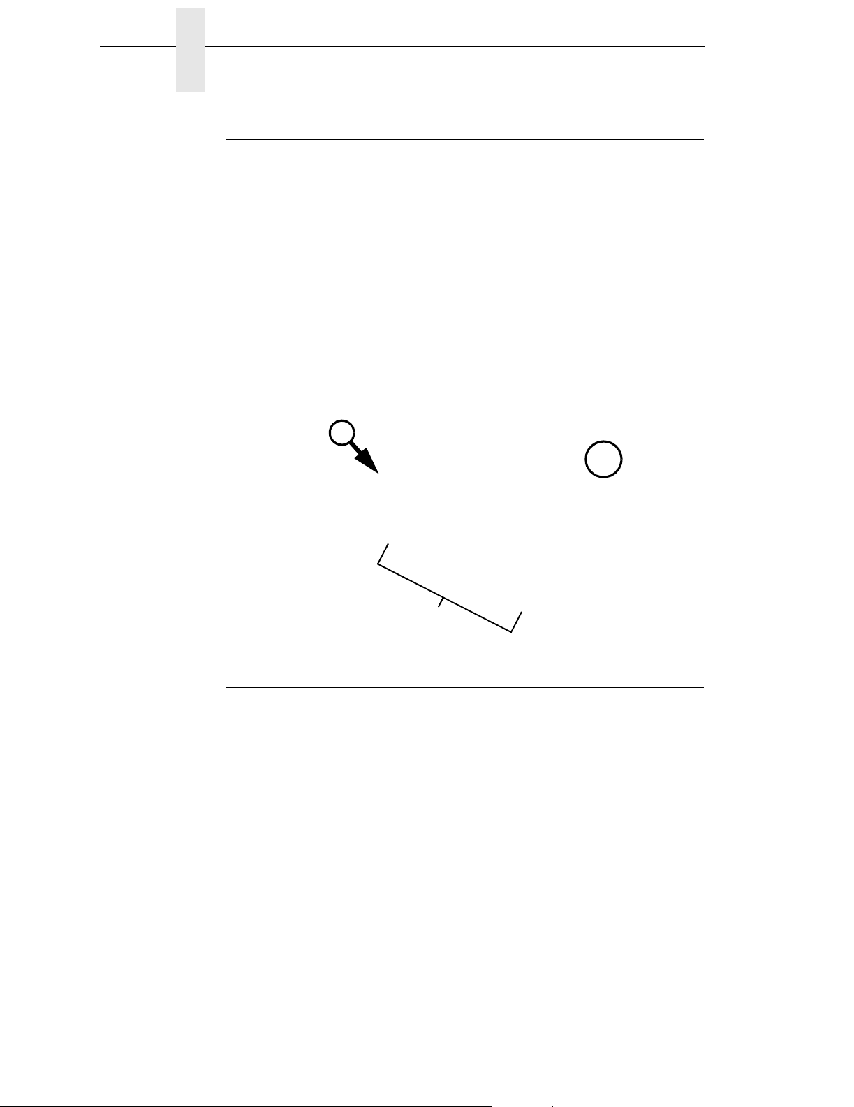
• In illustrations, magnified details are shown with locator arrows and
letters:
WARNING
This arrow points to an area . . .
the same page or a
subsequent page.
A
A
• Assemblies you can order as kits are shown in the following manner:
80
that is magnified here, on
To get item 80, 85, or 87, for
example, order item 90, which
is a kit containing all these
parts.
Notes And Notices
For your safety and to protect valuable equipment, always read and comply
with information highlighted under the following special headings:
A warning describes conditions that can harm you as well as damage
the equipment.
85
87
90
CAUTION
IMPORTANT
16
A caution describes conditions that can damage the printer or related
equipment.
Information vital to proper operation of the printer.
NOTE: Helpful and timesaving tips about printer operation and maintenance.
Page 17

Manual Conventions
Manual Conventions
• Control panel keys are printed in bold, uppercase letters.
Example: Press the PAUSE key to take the printer offline.
• Control panel keys are often shown by their symbol or icon (located on
the control panel directly below the key).
Example: Press the
• Liquid Crystal Display (LCD) messages are printed in uppercase letters
inside quotation marks ( “ ” ).
Example: When “OFFLINE” appears on the LCD, you may release the
PAUSE key.
• LCD fault messages display the specific fault in uppercase letters on the
top line. A corrective action in upper and lowercase letters displays on the
bottom line.
Example: PAPER OUT
Load Paper
↵ to select it.
• Key combinations (pressing keys at the same time) are indicated by the
+ (plus) symbol.
Example: Press ↓ +
↵ to unlock the ↵ key.
Related Manuals
This manual does not explain how to install, operate, configure the printer, or
how to program application software for operation with the printer. That
information is in the following manuals, available online at www.printronix.com:
• T5000 Thermal Printer User’s Manual
• T5000 Quick Reference Manual
• T5000 Maintenance Manual
• Network Interface Card User’s Manual
• Online Data Validator User’s Manual
• IGP
• IGP
• IPDS™ Programmer’s Reference Manual
• LinePrinter Plus
• Printer Protocol Interpreter 1.0 (PPI1™) Programmer’s Reference Manual
• Printer Protocol Interpreter 2.0 (PPI2™) Programmer’s Reference Manual
®
/PGL Emulation Programmer’s Reference Manual
®
/VGL Emulation Programmer’s Reference Manual
®
Emulation Programmer’s Reference Manual
17
Page 18
Chapter 1 Overview
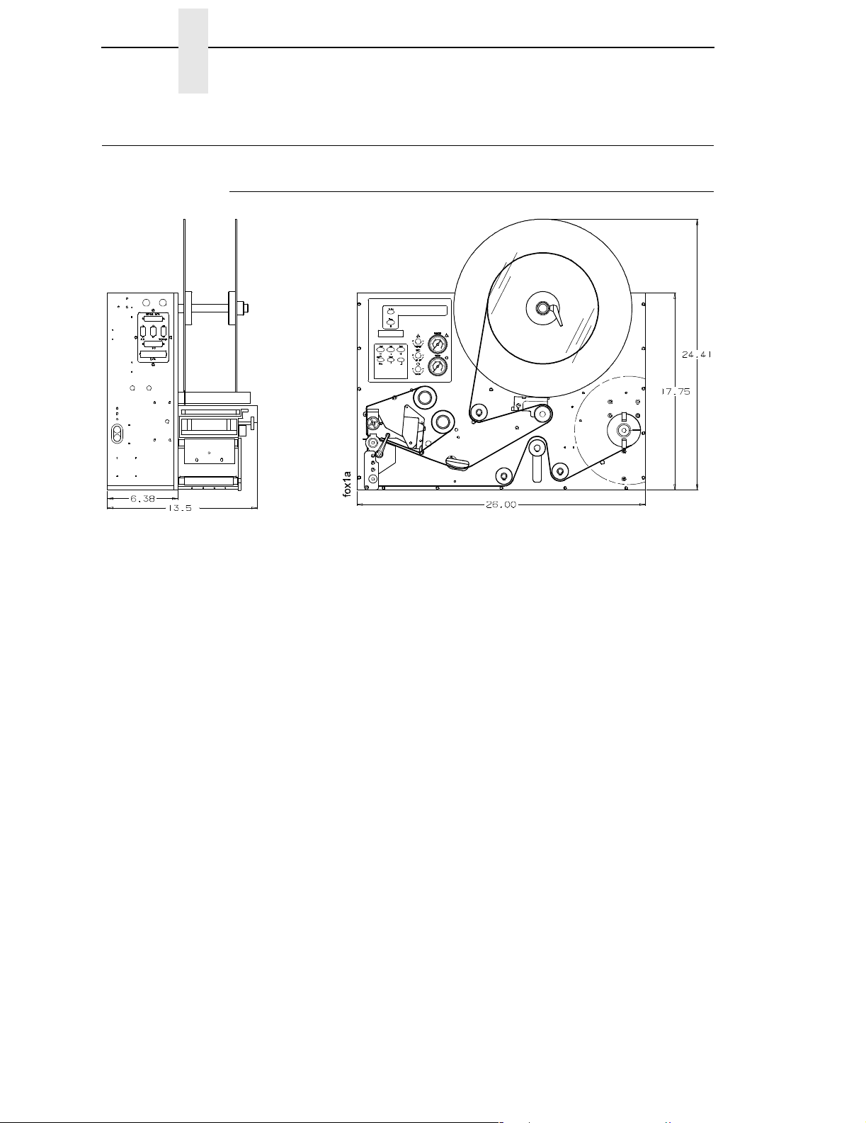
Overview
General Operation
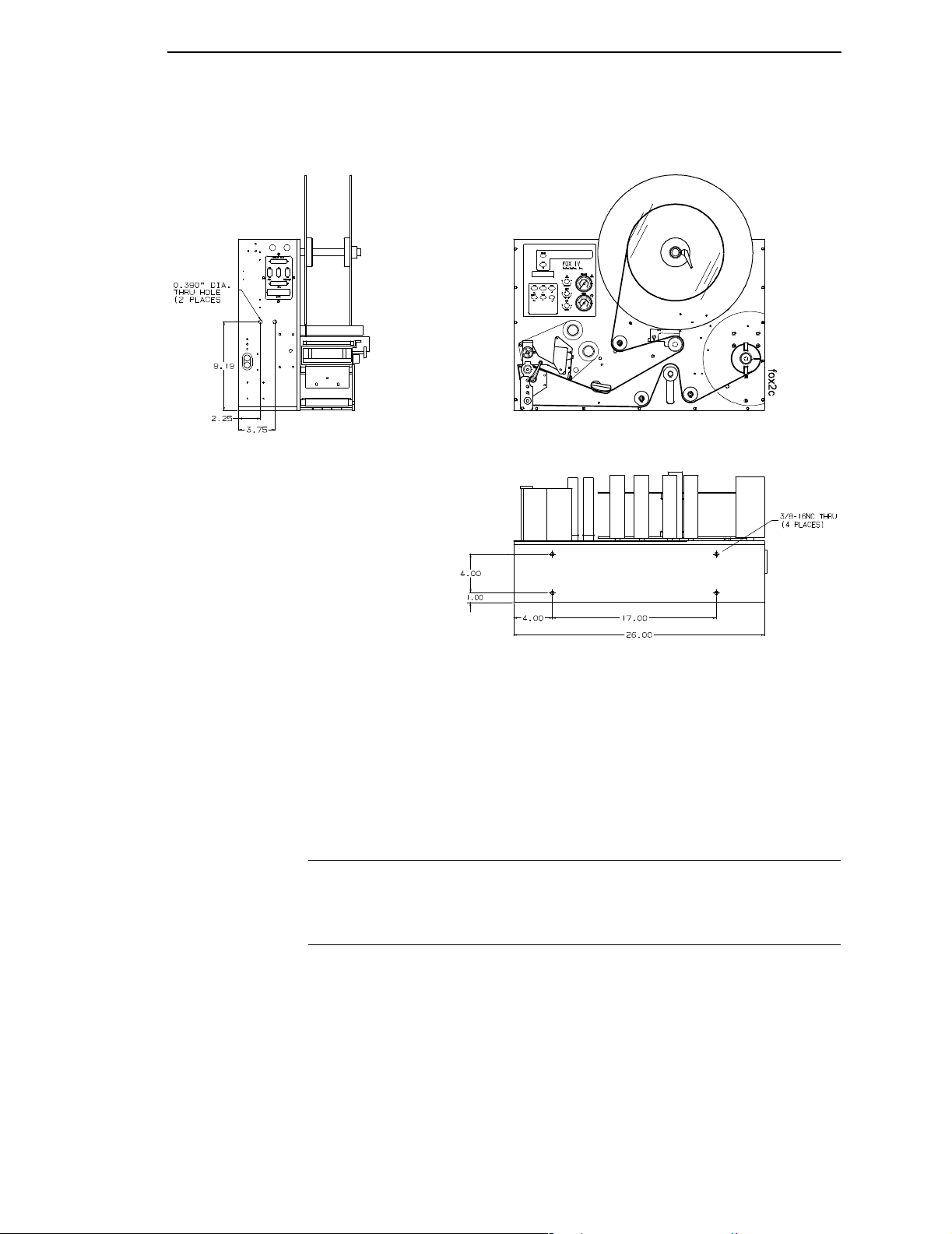
Figure 1. SLPA Dimensions
This document contains information and instructions for the Printronix Smart
Label Printer Applicator (SLPA). The SLPA can print label patterns up to 4.1
inches (104 mm) wide and applies them by means of a pneumatic applicator
system, although optional methods of applying the label are available by
design. The
menu configurations, as well as adjustments and basic maintenance
procedures the operator can perform.
The SLPA is both a direct thermal and thermal transfer label printer. The
SLPA can be positioned for top, side, or bottom applications and mounted
using the mounting holes in either the base or sides.
NOTE: Specify the orientation of the SLPA when ordering. If the system is to
The SLPA is an integrated unit composed of the following modules:
User’s Manual
be used for bottom applications, custom work may be needed.
contains information on setup, operation, and
• Label printer engine
• Label apply system
• GPIO control system
• Control panel (comprised of air controls, Liquid Crystal Display (LCD),
touch keypad/display, and air pressure gauges)
• Label supply
• Backing rewind system
18
These systems are packaged into a metal frame with an aluminum cover
enclosing the rest of the system. The metal frame is used for component
mounting, and all system controls are located on this frame.
Page 19

Operating Specifications
Operating Specifications
Operating Environment
The SLPA is designed for general use in warehouse and industrial
environments. It should not be exposed to liquids or damaging chemical
vapors, and will function properly in environments with an ambient
temperature between 40
exposure to dirt and dust is also recommended.
NOTE: Optional enclosures may be purchased to protect the products in
unusually harsh environments.
Power Requirements
A properly grounded, dedicated line supplying either:
115 VAC +
or
230 VAC +
10%, single phase @ 50 - 60 Hz
10%, single phase @ 50 - 60 Hz.
o
to 100o F (4o to 38o C). Minimizing unnecessary
CAUTION
CAUTION
It is recommended that you isolate the SLPA from its power supply by
means of a surge suppressor to minimize any potential damage to the
equipment.
A suppressor which limits voltage to 400V and has a response time of
1-5ns is highly recommended.
Air Supply
The applicator system works with a regulated 80 to 100 psi (550 to 690 kPa)
air supply that is dust and oil free. A filter is provided that is equipped with a
mist separator to remove any condensation that builds in the line.
The pneumatic supply line should also be dedicated to maintain the
appropriate pressure range, thereby providing relief against excess
pressure. Providing such protection should prevent the supply pressure
from exceeding 135 psi (931 kPA).
19
Page 20

Chapter 1 Overview
Storage, Shipping, & Handling
Storage
• Store the SLPA in a clean dry area.
• Storage temperatures should be between -40
• Do not store the SLPA with labels or printing ribbon installed.
• Store the SLPA in its original packaging if possible.
Shipping
• Observe storage conditions when shipping. Retain the shipping materials
if the SLPA is intended to be moved from site to site.
• If the original packing is not available, ensure sufficient padding/
protection for the printhead, applicator, label rollers, and rear cover.
• Carefully inspect the SLPA packaging upon receipt. If damage from
dropping, crushing, or punctures occurred, contact the carrier directly and
specify the nature of the damage.
o
to 150o F (-40o to 65o C).
Handling
• When handling the SLPA, do not rest or pivot it such that pressure may
be applied to the printhead assembly.
• Do not lift or pull the SLPA by gripping the applicator pad, the pneumatic
tubing, the printhead assembly, or any of the rollers which are located on
the front of the it.
NOTE: It is possible to manually position the applicator pad. Ensure that the
applicator pad is in the full up position to prevent any damage from
occurring when the SLPA is moved.
20
Page 21

Safety
Warnings And Cautions
Warnings And Cautions
WARNING
WARNING
WARNING
WARNING
CAUTION
Printronix has provided the necessary guards and warnings within the
confines of the SLPA, but cannot anticipate each customer’s individual
installation and operational environments. It is the customer’s
responsibility to provide in-house safety guards to provide adequate
worker safety for their respective production settings.
An input signal from the product sensor activates the SLPA when it is
powered on. Make certain that protective guards are properly secured
and that materials are clear of the applicator pad/printhead assembly
before powering on the SLPA.
This manual includes instructions on basic operation and preventative
maintenance only. Only qualified technicians should perform service
procedures, i.e, procedures requiring access to the rear compartment or
power entry module of the SLPA.
Both surge protection for the electrical supply and pressure relief for
the pneumatic supply are strongly recommended. Failure to properly
protect against extreme fluctuations in the supply sources could result
in operator injury or damage to equipment.
Power off the SLPA and disconnect both the power source and the air
supply prior to doing any maintenance, adjustments, and/or parts
replacement which do not require these systems to be powered on.
CAUTION
CAUTION
CAUTION
Read and become familiar with all of the instructions in this manual
before proceeding to operate the SLPA.
Any external communications cables to be used with the SLPA must be
properly shielded and grounded. Failure to provide proper shielding or
grounding for these cables could result in malfunctioning or damage to
the SLPA.
When handling the SLPA, do not rest or pivot it such that pressure may
be applied to the printhead assembly.
21
Page 22

Chapter 1 Safety
Operating Precautions
Proper operation of the SLPA depends upon timely maintenance and
appropriate operation. Always observe the following precautions:
• Use label stock which is designed for use with the SLPA. Printronix
• Ensure that a regulated air supply is used for the pneumatic system. Use
• Secure all protective guards, covers, and enclosures prior to operating
• Do not attempt to operate an SLPA from a power source other than that
• Use only Printronix replacement parts for maintenance and repair.
• You must have this manual to perform any maintenance. Use only the
• Do not use objects other than a finger to operate buttons on the keypad.
supplied replacement stock is recommended.
the appropriate filters for the removal of dirt, oil, and excessive moisture.
the SLPA. Ensure proper mounting of the SLPA prior to use.
for which it was designed. Do not use any of the SLPA’s components to
power or operate any equipment except those they are intended to
operate.
appropriate tools and ensure that maintenance workers are properly
grounded if work is being performed on the circuitry.
WARNING
WARNING
• Sound pressure levels indicated a maximum reading of 81 ±1dB(A).
Sound levels were determined based on printers of similar design and
assembled with a 3 x 4 inch applicator pad. Readings were taken in a low
noise environment, at approximately 1.0 meter.
NOTE: Sound levels may vary depending upon the mounting of the SLPA,
the surface to which a label is applied, and the environment in which it
is used. The size of the applicator pad can also affect sound levels, in
that larger pads can produce greater noise when applying labels.
Operational Safety
The addition of custom safety guards in the vicinity of the label
applicator is essential to the safe operation of the SLPA. Due to the
variety of potential assembly line setups, Printronix cannot provide
sufficient guarding in a standard package. The addition of such guards
is the responsibility of the buyer.
The SLPA should be powered off during any operation in which a
worker may be exposed to a hazardous zone. If it is necessary that the
SLPA remain powered on, make certain that the Pause button is pressed
and the product sensor is disconnected.
22
Page 23

The T5000e Series Label Printer
Standard Features
The T5000 Series is a family of direct thermal and thermal transfer printers
designed to print labels and tags from any MS-DOS
based computer.
Printronix Dynamic Print Control provides exceptional print quality. A circuit
monitors the data to be printed and automatically adjusts the energy applied
to the thermal printhead for maximum performance.
The printer can communicate with the host computer via RS-232 and RS-422
serial, Centronics
(optionally) coax/twinax, ethernet 10/100Base-T, or wireless ethernet host
connections. The interface cable needed to connect the printer to the host
device is supplied by the user.
®
-compatible parallel, IEEE® 1284 compliant parallel, and
®
, Windows®, or ASCII-
Standard Features
• Emulations:
• Printronix LinePrinter Plus (LP+). Provides direct compatibility with
Printronix P-series printers.
• Epson FX-1050, Proprinter IIIXL, and Serial Matrix printers.
• Printronix IGP/PGL and IGP/VGL. Provides printer system
commands for text, barcodes, graphics, lines, and boxes.
• Thermal Transfer and Direct Thermal Printing: On all printers
(except -DT models, which print only in direct thermal mode)
• Bar Codes: Support for over 20 types of bar codes
• Resident Fonts: OCRA, OCRB, Courier, Letter Gothic, and
CG Triumvirate Bold Condensed
• Download: Forms, fonts, and graphics into printer memory
• High Resolution Printhead: For sharp graphics and text
• Label Taken Sensor: For detecting removal of labels in Tear-Off mode
(and in Peel-Off mode when optional rewinder is installed)
• Tear-Off Mode: For positioning the label at the tear off position and
detecting its removal before printing the next label
• Tear-Off Strip Mode: For printing a specified number of labels and
positioning the last label at the tear off position
• 8MB DRAM memory
• 4MB Flash memory
• Auto Label Mapping
Printronix line matrix printers.
®
: For compatibility with programs written for
• Ventless System: For operation in environments with airborne
particulate matter without compromising performance
23
Page 24

Chapter 1 The T5000e Series Label Printer
Optional Features
The following options are also available:
• PPI1 and PPI2 Interpreters: PPI1 (Zebra
interpreters are powerful integration tools that allow the SLPA to function
in virtually all legacy ZPL and TEC application environments without
requiring modifications to the host data stream. PPI1 (Zebra) enables you
to print files formatted for Zebra printers to the Printronix SLPA. PPI2
(TEC) prints files formatted for TEC printers to the Printronix SLPA.
• Fonts: A selection of fonts can be loaded from the host computer into
printer memory. Once loaded, these fonts are accessed in the same way
as the resident fonts. See Table 17 on page 358 for a list of optional fonts.
• Memory Expansion (for non-IPDS printers only):
• 16MB DRAM SIMM (single in-line memory module): Provides
additional memory to accommodate long label formats.
• 10MB Flash SIMM: Provides additional memory for forms, logos, and
fonts.
• Heavy Duty Media Cutter: Automatically cuts up to 0.010” thick printed
tag stock as the media exits the printer. Available for 4, 6, and 8 inch
printers.
®
) and PPI2 (TEC®)
• Standard Duty Media Cutter: Automatically cuts up to 0.008” thick
printed tag stock as the media exits the printer. Available for 4 inch
printers only.
• Twinax/Coax Host Interface: Provides connection to a host computer
system using a coaxial or twinaxial interface.
• Dual NIC (10/100Base-T & 802.11b wireless): The Dual NIC (network
interface card) provides both 10/100Base-T or 802.11b wireless
connectivity in one. The card provides wireless connectivity without the
expansive cabling and reconfigurations required from a wired network. It
also provides 10/100Base-T for wired network and wireless back up. The
remote management software, a powerful printer management tool, is
standard with the Dual NIC (10/100Base-T & 802.11b wireless).
• NIC (10/100Base-T) Internal or External: The NIC 10/100Base-T
connectivity option provides wired networks in either an internal or
external option that allows you to attach the printer to a LAN (local area
network) instead of directly to a host computer. The remote management
software is standard with this option.
• IPDS: Available for coax/twinax, a NIC, or a combination of both. The
printer may be ordered with this option installed and the required
hardware to support it, or it can be field installed by an authorized service
representative at a later date. The printer must have a coax/twinax
interface or NIC, 300 dpi printhead, 16 MB DRAM, and 10 MB flash
memory installed to support this field-installed option.
• TN5250/TN3270: Enables your printer to communicate with an IBM host
through a NIC using the 5250/3270 datastream. This feature allows you
to use an application generated for the twinax/coax emulation to be
printed through the NIC.
24
Page 25

Thermal Printer Media
Thermal Printer Media
Because there are two modes of operation, there are two kinds of thermal
printer paper:
• Direct thermal paper: This paper is coated with chemicals that act as
accelerators, ink, and ink binders. In direct thermal mode, the heat from
the thermal printhead contacts the paper and causes a chemical reaction
on the surface of the paper.
• Thermal transfer paper: This film or synthetic paper substitute is
designed to accept transferred images well and to resist scratching. Most
thermal transfer papers can be die-cut for easy label applications.
Printronix offers a selection of thermal transfer paper sizes and face
stocks, which ensures high print quality and long life when used with
Printronix ribbons.
Ribbons
Use only Printronix Genuine Thermal Ribbons in this printer. Printronix
thermal ribbons are engineered to enhance thermal printing capabilities and
to prevent premature wear of the printhead.
Thermal Printer Technology
Unlike a dot matrix, laser, or LED printhead printer, a thermal printer has a
printhead containing heating elements that are used with paper or a ribbon
specially designed for use with a heated printhead. The SLPA uses an inline
thermal printhead, which produces high resolution output quickly and
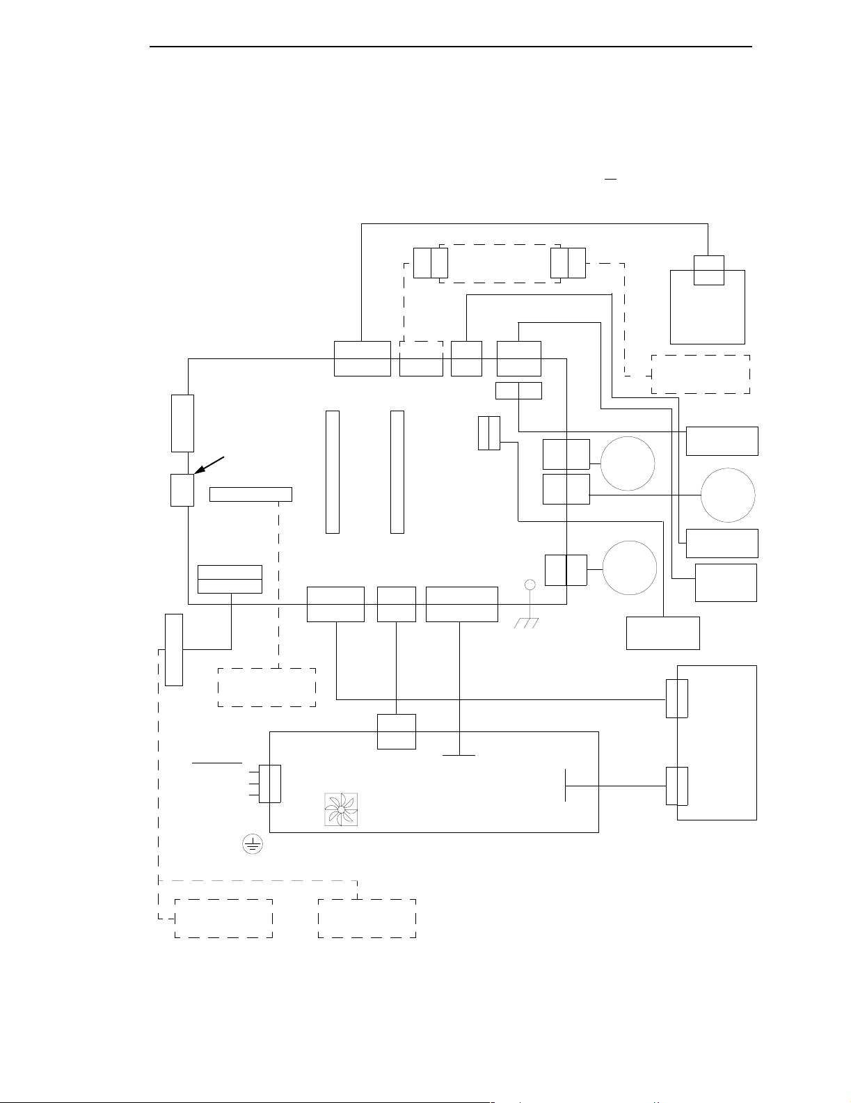
efficiently. The architecture of the SLPA is shown in Figure 2.
The Printing Process
The thermal printhead allows two modes of operation:
• Direct Thermal Mode: The thermal printhead selectively heats tiny
rectangular
coated thermal paper, the dyes and developers in the coating react to the
heat and develop an image. This mode of printing is often used for shortterm labeling applications.
• Thermal Transfer Mode: The heated dots contact a thermal ribbon; the
thermal ribbon reacts to the heat by bonding the image to the paper. This
method is especially suitable for print applications requiring long-term
storage, abrasion resistance, durability in extreme environmental
conditions, and resistance to tampering. (Models designated -DT do not
print in this mode.)
dots on its surface. When the heated dots contact specially
25
Page 26

Chapter 1 The T5000e Series Label Printer
Dynamic Print Control
Print quality in thermal printers depends on how well the thermal ribbon and
thermal transfer paper respond to the heat of the thermal printhead. The
thermal printhead must reach a specific temperature to print, then must cool
down in the shortest possible time after printing. Print quality therefore
depends on precise control of the energy supplied to the thermal dots. If
uneven print density occurs, it is usually caused by the stored heat from dots
printed previously.
The SLPA uses Dynamic Print Control technology to ensure even print
density. Dynamic Print Control is printer software that monitors and adjusts
printhead temperatures. Based on stored results of previously printed dots,
the printer predicts the amount of heat required to print subsequent dots and
regulates the electrical energy applied to the printhead. This prevents uneven
print density and permits the printing of narrow-ladder bar codes and vertical
grid lines that are absolutely straight.
26
Page 27
Thermal Printer Technology
J2
J3
J203
Parallel
Serial
Port
DB25
Port
Diagnostic Port
DB9
Expansion Port
J4
J112
P112
P13
J13
J38 J33
Flash DRAM
SIMM SIMM
J6
P6
J5
P5
J2P2
P9
J9
Controller
Cutter
PCBA Option
P11
J11
J
P
1
1
5
5
J17
P17
J21
P18
J18
P21
J16
J14
J8
P1J1
P8,
16
P14
P8,
16
Ribbon
Supply
Motor
Ribbon
Take-up
Motor
Lower Media
P301
J301
Control
Panel
Cutter Option
Upper Media
Sensor
Stepper
Head Up
Sensor
Label
Taken
Sensor
Sensor
Motor
Expansion-CT
AC Power
Line 1
Line 2/neutral
Ground (green/
yellow wire)
Ethernet NIC
Option
Option
J201
P403
CN403
Fan
Wireless Dual
NIC Option
Power Supply
Figure 2. Functional Block Diagram
P401
P402
J401
Thermal
Print
Head
J402
27
Page 28

Chapter 1 Installing The SLPA
Installing The SLPA
Unpacking Your SLPA
The SLPA has been securely packaged for protection during transportation.
Once received, follow the steps outlined below to ensure that the SLPA is not
damaged.
1. Remove the top layer of protective paper from the SLPA.
2. Lift the SLPA from the protective bottom layer of the box.
CAUTION
Do not lift or pull the SLPA by gripping the applicator pad, the
pneumatic tubing, the printhead assembly or any rollers which are
located on the front of it.
3. Save the shipping container and protective layers of paper to ensure
proper return shipping to Printronix, if necessary.
4. Organize all items as they are unpacked from their containers. Carefully
inspect each item for signs of damage. Make certain that all parts
(options) requested are received with the order.
5. Consult the enclosed packing slip for contact information if any item is
missing or broken.
Mounting The SLPA
The mounting method for the SLPA allows for side, top, or bottom
applications.
NOTE: Specify the orientation of the SLPA when ordering. If the system is to
be used for bottom applications, custom work may be needed.
If the bottom base plate is used, the SLPA can easily be mounted to any flat
surface using the four 3/8 - 16 UNC holes provided. If the SLPA is mounted
using the 0.39 inch diameter holes provided on the side panels, special
fixturing may be needed to prevent potential damage to the connectors and
cabling in those areas.
28
To facilitate access to the control panel, the SLPA should be mounted at a
height between 2.0 feet (0.6 m) to 6.2 feet (1.9 m) above service level.
Page 29
Optional Mounting Accessories
CAUTION
IMPORTANT
Figure 3. Mounting Hole Configuration
The mounting plates of the SLPA are 0.375 inches (9.25 mm) thick.
When mounting the SLPA, use screws that will secure the assembly into
place but will not penetrate deeper than 1/2 inch (12.7 mm) in the SLPA.
Retain cap screws in mounting holes that are not to be utilized.
Optional Mounting Accessories
See “Mounting Accessories” on page 328.
Mounting The Beacon
See “Mounting The Beacon” on page 327.
29
Page 30
Chapter 1 Installing The SLPA
Air, Power, And Communications Connections
CAUTION
Any external communications cables to be used with the SLPA must be
properly shielded and grounded. Failure to provide proper shielding or
grounding for these cables could result in malfunctioning or damage to
the SLPA.
After mounting the SLPA, connect the system as follows:
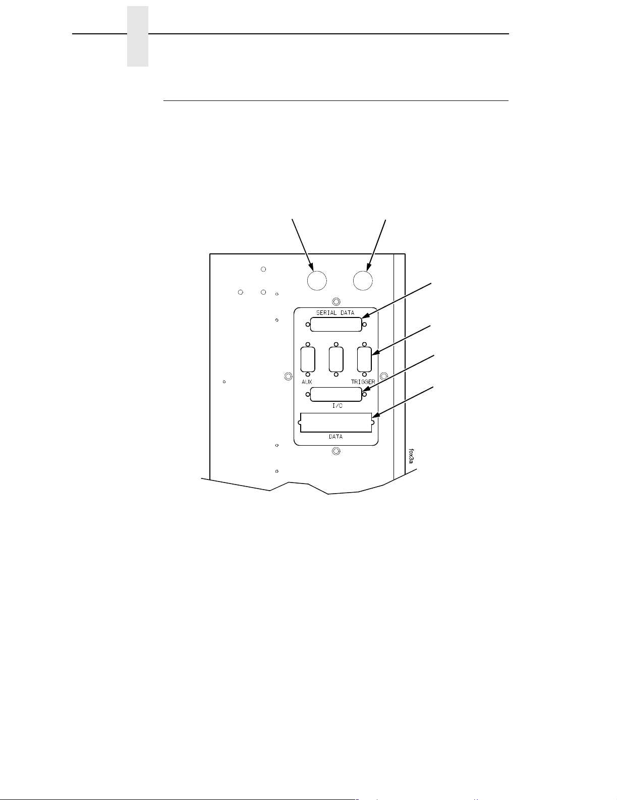
Beacon
Port
Pad Home
Port
Serial Data
Port
Trigger Port
I/O Port
Data Port
30
Figure 4. Interface Panel
1. Connect the pad home sensors mounted on the air cylinder to the pad
home port on the interface side panel. (Figure 4.)
2. Connect the interface cable to the serial data port.
3. Connect the opposite end of the interface cable to the serial
communications port of the host which will provide data.
4. Connect the product sensor connector to the trigger port.
NOTE: The I/O port is used to communicate with the SLPA’s GPIO inputs
and outputs if the optional fault/warning applicator control package is
installed.
5. If you have the IEEE-1284 parallel communications cable option, attach it
to the data port.
Page 31

Air, Power, And Communications Connections
Air Pressure
Adjustment Knob
Air Pressure
Gauge
To Air
Supply
Hose
IN
Air Supply
Connector
Air Hose to
SLPA
OUT
Quick
Connect
Air Fitting
Figure 5. Air Filter
6. If you have a fault warning beacon, connect it to the beacon port.
(Figure 4.)
The fault warning beacon can also be mounted remotely from the SLPA.
(An optional 12 feet cable extension is available.)
7. Mount the air filter according to requirements.
NOTE: Customer must provide the necessary mounting for the air filter
supplied with the system.
8. Connect the air supply hose to the air supply connector marked IN.
(Figure 5.)
9. Connect the air hose to the quick connect air fitting marked OUT.
31
Page 32

Chapter 1 Installing The SLPA
Quick
Connect
Air Fitting
Power Switch
AC Power
Receptacle
Figure 6. Power Panel
10. Connect the opposite end of the air hose to the quick connect air fitting on
the power panel. (Figure 6.)
NOTE: Make certain that all communication port parameters have been
configured according to purchase order requirements. Print
parameters must be programmed correctly to achieve the best
possible print quality. The factory settings are sufficient for most
applications. Refer to “Configuring The SLPA” on page 73 to
customize printing setup.
11. Adjust the air pressure to 90 ±10 psi using the air pressure adjustment
knob and the air pressure gauge (Figure 5): pull up the knob, then rotate it
clockwise to increase pressure or counterclockwise to decrease pressure.
Push in the knob when you have set the pressure.
12. If necessary, adjust the voltage (page 33).
13. Plug the AC power cord into the AC power receptacle. (Figure 6.)
14. Plug the SLPA and computer AC power cords into a grounded (three
prong) electrical outlet of the proper voltage.
32
15. Set the power switch to | (On) to power on the SLPA.
Page 33

AC Power
Receptacle
Selected
Voltage
Adjusting The Voltage
Facing
Arrows
Adjusting The Voltage
Power
Switch
Slot
Fuse Holder
Assembly
The facing arrows indicate the selected voltage setting. (Figure 7.). If the
setting is incorrect, adjust the voltage as follows:
1. Set the power switch to O (Off).
2. Insert the tip of a flat tip screwdriver into the slot above the fuse holder
3. Flip over the fuse holder assembly and make sure the fuse is in the active
NOTE: Refer to “Electrical” on page 322 for fuse electrical specifications.
Active Fuse
Figure 7. Adjusting the Voltage
assembly, and twist to remove the assembly.
fuse location.
4. Reinsert the fuse holder assembly. Make sure the facing arrows are
aligned properly.
33
Page 34

Chapter 1 Installing The SLPA
34
Page 35

2 Operation
Control Panel
The operation and system status of the SLPA are provided on the control
panel. Information concerning the SLPA is displayed on the liquid crystal
display (LCD), while commands are given to the SLPA through the control
panel keypad. Control valves are provided for refined adjustments to the
pneumatic system.
IMPORTANT
Online
Status
Indicator
Liquid
Crystal
Display
(LCD)
Data
Indicator
It is important to become familiar with all of the operations, readouts,
and components of the control panel. Inappropriate settings may impair
the SLPA’s functionality.
Figure 8. Control Panel
35
Page 36

Chapter 2 Control Panel
LCD
The LCD is a 2 line by 16 character per line reflective display with a light
emitting diode (LED) backlight. The LCD displays system information on the
SLPA when performing system set-up procedures, print batch status during
operation, and system information in a fault condition.
Keypad
The keypad is used to place the SLPA in operation, to perform calibration or
testing, or to modify the systems operating parameters.
The keypad functions as two key groups: SLPA control when the SLPA is
online, and menu option setting when the SLPA is offline. The use of one key
group will not interfere with the use of the other key group. The function of
each indicator and key is defined in Table 1.
Table 1. Control Panel Keys
Indicator or
Key
Online Status
indicator
Liquid Crystal
Display (LCD)
Description Online Mode Offline Mode Menu Mode
Indicates when
SLPA is online,
offline, or in fault
condition.
A 2 line by 16
character per
line reflective
display with a
light emitting
diode (LED)
backlight.
Light is on when
online, ready to
print, and accept
data from host.
Flashes during
fault condition.
Displays
ONLINE, the
interface type,
and emulation in
use.
During a fault
condition,
displays specific
fault message
and required
action.
Light is off when
SLPA is offline.
Flashes during
fault condition.
OFFLINE
During a fault
condition,
displays specific
fault message
and required
action.
Light is off.
Flashes during
fault condition.
Displays
OFFLINE, a
Main menu and
submenu, or
option.
During a fault
condition,
displays a
specific fault
message and
required action.
Pause key Switches the
SLPA between
online and
offline modes.
36
Pressing this
key when the
SLPA is online
takes the SLPA
offline.
Pressing this
key when the
SLPA is offline
places the SLPA
online.
Takes the SLPA
offline.
Page 37

Table 1. Control Panel Keys
Keypad
Indicator or
Key
Description Online Mode Offline Mode Menu Mode
Print key Print key
– (decrease) key
in Menu mode.
Feed key Feed key
↑ (up arrow) key
in Menu mode.
Apply key Apply key
+ (increase) key
in Menu mode.
Menu key
Data indicator
Menu key
Data indicator is
green when data
is in the system.
Prints the next
label in the
buffer.
Advances the
media one label
length.
Manually applies
the label.
Takes the SLPA
offline and
selects Menu
mode.
None Scrolls left
through current
menu options.
Decreases
option values in
submenus.
None Scrolls current
menu selection
up one level.
Selects the
Printer Tests
menu, and then
Scrolls right
through current
menu options.
scrolls through
the options.
Increases option
values in
submenus.
Enters Menu
mode.
Scrolls through
the Main menu
selections.
Cancel key Pressing the
Cancel key will
enable the key
and clears all
data from the
print buffer and
prevent printing
of that data.
1
↓ (down arrow)
key in Menu
mode.
↵ (Enter) key Pressing the ↵
(Enter) key in
Menu mode
selects the
displayed option
or value.
1
Cancel Key must be set to Enable in the PRINTER CONTROL menu to use
the Cancel key. The default is Disable.
None Clears all data in
the print buffer.
Selects the
Applicator Delay
menu
(page 152).
When in the
Printer Tests
menu, runs the
selected test.
Scrolls the
current menu
selection down
one level.
Selects the
current menu
value.
37
Page 38

Chapter 2 Control Panel
Key and Indicator Descriptions
For the locations of these keys and indicators, refer to Figure 8 on page 35.
Online Status Indicator
The SLPA is online when the Online status indicator light is on. When the
SLPA is offline, the light is off.
Pause Key
When the SLPA is online or in Menu mode, the Pause key takes the SLPA
offline (offline mode) and suspends all SLPA operations, but operations do
not cease until the current print or apply cycles have been completed. When
the SLPA is offline, the operator may make mechanical adjustments to the
SLPA, clear assembly line jams, etc., without powering off the system.
When the SLPA is offline, the Pause key places the SLPA back online (online
mode).
NOTE: The SLPA may automatically take itself offline in several situations
(e.g., out of labels, after recovering from a fault, etc.).
Print Key
When the SLPA is online, the Print key prints a label and feeds it to the
applicator pad if there is a label configuration in the SLPA’s print buffer. If no
label pattern exists in the buffer, it will not function.
In Menu mode, the – (decrease) key scrolls left through current menu options
or decreases option values in submenus.
NOTE: The Print key has no effect when the SLPA is offline.
Feed Key
When the SLPA is online, the Feed key advances the media one label length.
if the print buffer is currently empty. If the system is printing labels from the
buffer, this key will not function until the batch is done printing.
In Menu mode, the ↑ (up arrow) key scrolls the current menu selection one
level up.
NOTE: The Feed key has no effect when the SLPA is offline.
Apply Key
When the SLPA is online, the Apply key cycles the applicator as though the
SLPA was triggered by the product sensor. The cylinder extends to place the
label and a new label prints and is placed on the pad upon its return to the
home position.
In Menu mode, the + (increase) key scrolls right through current menu options
or increases option values in submenus.
38
Page 39

Key and Indicator Descriptions
Menu Key and Data Indicator Light
When the SLPA is either online or offline, the Menu key takes the SLPA
offline and into Menu mode.
In Menu mode, the Menu key scrolls through the Main menu of the SLPA’s
operating system. It permits the operator to set or change various operating
parameters.
The Data indicator light on the Menu key is green when data is in the system.
This data refers to the information printed on the label. If the green light is off,
there is no data in the system. There is no manual operation of this indicator.
Cancel Key
NOTE: Cancel Key must be set to Enable in the PRINTER CONTROL menu
to use the Cancel key. The default is Disable.
When the SLPA is offline, the Cancel key clears the current print pattern and
all printing programs currently in the print buffer.
After clearing the print buffer, the SLPA automatically takes itself offline. The
SLPA may then have a new label pattern downloaded to the print buffer.
Press the Pause key to place the SLPA back online.
In Menu mode, the ↓ (down arrow) key scrolls the current menu selection one
level down.
NOTE: The Print key has no effect when the SLPA is online.
↵
(Enter Key)
When the SLPA is online, the ↵ (Enter) key selects the Applicator Display
Menu (page 152).
When the SLPA is offline, the
or parameter value within the submenus. Press
parameter.
In Menu mode, the
↵ (Enter) key selects the current value.
↵ (Enter) key is used to select a menu option,
↵ to select a menu option or
39
Page 40

Chapter 2 Control Panel
Pneumatic Control Valves And Gauges
Air Cylinder Regulator
NOTE: You may also adjust the cylinder delay time through the Applicator
Delay menu. See “Applicator Delay Menu” on page 152.
The air cylinder regulator (CYLINDER valve) is used to regulate the air to the
applicator cylinder. The regulator setting affects how quickly the applicator
pad will extend (apply stroke) and return (return stroke) during the apply
cycle. This adjustment determines the force with which the applicator pad will
contact the product. If set too high, the applicator pad could contact the
product with enough force to cause damage. If set too low, the applicator pad
may not contact the product. The air pressure delivered for the apply stroke
and the return stroke is equal.
Monitor the setting of the air cylinder regulator using the PRESSURE gauge.
Air Jet Adjustment
The air jet adjustment (AIR JET) controls the air supply to the air jet tube. Air
is forced out the air jet tube allowing the labels to properly transfer over the
peel bar then to the applicator pad. If the adjustment is too low, the labels will
not properly transfer from the printer to the applicator pad. If set too high, the
label edge will be incorrectly positioned. The air jet is factory preset. Adjust
the air jet pressure by turning the AIR JET control clockwise to increase the
flow, counterclockwise to decrease the flow. See “Positioning The Air Jets” on
page 52.
Vacuum Adjustment
NOTE: You may also adjust the vacuum delay time through the Applicator
Delay Menu. See “Applicator Delay Menu” on page 152.
The vacuum adjustment (VACUUM) controls the amount of air flow through
the vacuum generator, thus determining the amount of vacuum holding the
label onto the applicator pad. A weak vacuum will cause labels to fall off of the
applicator pad prematurely. A vacuum that is too strong, however, can cause
difficulty when transferring the label onto the applicator pad and the product.
Vacuum is increased by rotating the valve clockwise and decreased by
rotating the valve counterclockwise.
NOTE: To get a vacuum on every label, every hole on the applicator pad
must be covered by the label surface.
Monitor the setting of the vacuum adjustment using the VACUUM gauge.
40
Page 41

Setup
Removing Label Backing
Removing Label Backing
If the media rewind spool needs to be unloaded during operation, proceed as
follows:
1. Press the Pause key to take the SLPA offline. Disable the product sensor
if necessary.
2. Tear the label backing near the media rewind hub, then reach around the
rewound backing, placing your fingers behind the hub of the media rewind
spool.
3. Pull the rewind spool away from the centerwall plate until the rewind
release bars collapse toward the center of the hub, then pull off the used
label backing. The rewind hub will snap back into position near the
centerwall once the used label backing is removed.
4. Feed a few blank labels by inserting the new edge of the label backing
into the slit on the rewind spool and manually rotate the spool at least one
turn counterclockwise.
5. Press the Pause key to place the SLPA online then enable the product
sensor to continue operation.
Threading The Label Roll
Pivoting Deck
Deck Lock Lever
Figure 9. The Printhead Assembly
41
Page 42

Chapter 2 Setup
1. Press the Pause key to take the SLPA offline.
2. Open the pivoting deck by rotating the deck lock lever fully clockwise.
Label Roll Hub
Label Roll Core
Label Roll
Retainer
Label Roll Hub
Collar
Cam Lock
Figure 10. Mounting Label Media
3. Loosen the cam lock located on the collar of the label roll hub.
4. Slide the label roll retainer off the label roll hub.
5. Remove the empty label roll core, if necessary, from the label roll hub.
42
Page 43

Label
Threading The Label Roll
Label Roll
Back Stop
Label Roll
Spindle
Label Roll
Retainer
Collar
Label Roll
Cam Lock
Figure 11. Loading Label Media
6. Slide the new label roll onto the label roll hub (unwinding
counterclockwise) and against the label roll back stop.
7. Angle the flat edge of the collar so that it aligns with the flat edge of the
label roll spindle.
8. Place the label roll retainer onto the label roll spindle until it is flush with
the label roll, then tighten the black cam lock.
NOTE: If necessary, loosen the set screw on the collar and adjust the core
blade so that it cuts into the label core.
43
Page 44

Chapter 2 Setup
Label Roll
Retainer
Label Roll
Brake
Assembly
Printhead
Platen
Label
Media Damper
Backing (Liner) Path
Figure 12. Loading Labels
9. Unwind approximately 3.0 feet (91cm) of media from the label roll. If your
label roll does not have a leader, remove the labels from the backing. The
empty backing (leader) will act as a leader to thread the media through
the SLPA components.
10. Pull the brake assembly away from the label roll back stop (behind the
label roll retainer) to release the tension.
11. Thread the leader around the rollers and toward the media damper using
the solid white arrow threading diagram etched on the front center wall
plate.
44
Page 45

Media Guard
Threading The Label Roll
Lower Media
Sensor
Leader
Fixed Guide
Media Sensor
Handle
Media Damper
Media Width
Guide
Figure 13. Threading Media Through the Printhead Assembly
12. Slide the media width guide close to the outside end of the media
damper.
13. Thread the leader under the media damper and then between the platen
(rubber drive roller) and the printhead.
14. Verify that the inside edge of the leader is against the fixed guide on the
bottom of the media damper.
15. Push the media width guide in until it is flush with the outer edge of the
media.
NOTE: Do not wrinkle the leader by pushing the media width guide too close
to the SLPA panel.
16. Check the horizontal position of the lower media sensor (located under
the media guard). See “Positioning The Media Sensors” on page 56.
45
Page 46

Chapter 2 Setup
Printhead
Assembly
Upper Media
Sensor
Visible Red Beam
Lower Sensor
Upper Sensor
Handle
Platen Roller
Figure 14. Threading the Leader
17. Slide the upper sensor directly over the lower sensor.
18. Thread the leader between the printhead assembly and across the top of
the platen roller.
46
Page 47

Peel Bar
Threading The Label Roll
Media Edge
Platen
Figure 15. Aligning Media
19. Align the inside edge of the media with the inside edge of the peel bar.
20. Thread the leader over the peel bar, then between the lower platen roller
and the air jet.
21. Follow the label guide arrows from the printhead, around the rollers to the
media rewind spool.
22. Fold the leading edge of the leader and insert it into the slit on the rewind
spool. Make sure the leader lines up closely to the SLPA panel.
23. Manually rotate the spool at least one turn counterclockwise.
NOTE: Hold the leader down while rotating the rewind spool to keep the
leader in place.
24. If the SLPA is being used in Thermal Transfer mode, it may be necessary
to load ribbon. See “Loading Ribbon” on page 49, otherwise proceed as
follows.
47
Page 48

Chapter 2 Setup
Pivoting Deck
Deck Lock
Lever
IMPORTANT
Figure 16. Locking the Pivoting Deck
25. Ensure that the label path is clear of obstructions, then close the pivoting
deck and rotate the deck lock lever fully counterclockwise. This locks the
pivoting deck and printhead assembly into the printing position.
Ensure the pivoting deck is down and locked before attempting to
advance media or print. Failure to do so will cause the PRINTHEAD UP
fault message to display.
26. Press the Pause key to place the SLPA online, and send a label format
via the host.
48
Page 49

Pivoting Deck
Loading Ribbon
Loading Ribbon
Ribbon Take-Up Core
Ribbon Take-Up
Spindle
Ribbon Supply
Spindle
Ribbon Roll
Deck Lock Lever
Figure 17. Loading Ribbon
1. Press the Pause key to take the SLPA offline.
2. Install the ribbon take-up core on the ribbon take-up spindle.
NOTE: The first ribbon take-up fiberboard core comes with the SLPA.
Thereafter, use the fiberboard core from the old (used up) ribbon.
3. Slide the ribbon roll onto the ribbon supply spindle until it stops against
the spindle flange.
4. Open the pivoting deck by rotating the deck lock lever fully clockwise until
the deck swings upward.
49
Page 50

Chapter 2 Setup
Printhead
Ribbon
Rear Ribbon
Guide Roller
Figure 18. Threading Ribbon Through the Printhead Assembly
5. Thread the end of the ribbon under the rear ribbon guide roller, then
between the platen and the printhead using the dotted line etched on the
front center wall plate.
50
Page 51

Ribbon
Loading Ribbon
Ribbon
Take-up Core
Ribbon
Take-up Spindle
IMPORTANT
Figure 19. Attaching the Ribbon to the Take-up Core
6. Wrap the ribbon from the front of the printhead assembly to the top of the
ribbon take-up spindle. Attach the ribbon to the take-up core on the ribbon
take-up spindle with tape.
When installing a new roll of ribbon, attach the ribbon leader adhesive
strip to the ribbon take-up core. Manually rotate the spindle clockwise to
feed the unusable portion of the ribbon leader around the take-up spindle.
Do not attach the ribbon to the ribbon take-up spindle without a ribbon
take-up core installed.
7. Close the pivoting deck and rotate the deck lock lever fully
counterclockwise.
8. Press the Feed key once to verify that the media and ribbon advance.
9. Press the Pause key to place the SLPA online, then send a label format
via the host.
51
Page 52

Chapter 2 Setup
Positioning The Air Jets
When a printed label is being fed from the SLPA onto the applicator pad, it
must be held against the pad so that it can be properly positioned. The air jets
located on the air jet tube direct air at the label while it is being fed, so that it
does not bend or fall from the pad. Once proper positioning is achieved, the
vacuum of the applicator pad initiates and holds the label into place until
application.
For the air jets to work correctly, they must be directed at an angle specific to
the size of the label in use. Angle the air jets to a point which is approximately
1/3 the length of the current label length, as measured from the peel bar.
Wider or longer labels may approximate the air jet angle to a point beyond 1/3
the label length, where shorter or narrower labels may target inside the 1/3
length zone. Repeated adjustment may prove necessary for optimum
operation.
Label
Peel Bar
Label Backing
Socket Head
Screw
Air Jet
Air Jet Tube
Figure 20. Positioning the Air Jets
The air jet will typically be adjusted for proper operation prior to being
shipped, but if further adjustments are necessary, proceed as follows:
1. Loosen the socket head screw holding the air tube into place.
2. Ensure that the proper holes in the air jet are open. The standard tube
comes with #2-56NC threaded holes and some of the holes may be
plugged with a small set screw. Add or remove set screws as necessary.
3. Turn the air tube adjustment so that the air jets are directed at
approximately 1/3 the length of the current label length as measured from
the peel bar.
52
4. Tighten the socket head screw into place to hold this adjustment.
Page 53

RFID System Configuration Parameters
The following is a list of the four system configuration parameters required for
the operation of the SLPA as an RFID label printer/applicator. They are Media
Handling, RFID Reader, GPIO Port, and GPIO Table.
NOTE: You may need to set or configure other parameters for proper SLPA
operation.
Media Handling
This item selects the method of media handling.
1. Press the Menu key to take the SLPA offline and into Menu mode.
2. Press the Menu key to scroll through the Main menu until QUICK SETUP
displays.
3. Press either the ↑ or ↓ key to scroll through the QUICK SETUP submenu
until Media Handling displays in the first line of the LCD.
4. Press the + or – key to scroll through the parameters until Tear Off
displays on the second line of the LCD.
Positioning The Air Jets
5. Press the Enter key to select Tear Off.
RFID Reader
This enables the RFID Reader.
1. Press the Menu key to take the SLPA offline and into Menu mode.
2. Press Menu key to scroll through the Main menu until RFID CONTROL
displays.
3. Press the ↑ or ↓ key to scroll through the RFID CONTROL submenu until
RFID Reader displays in the first line of the LCD.
4. Press the + or – key to scroll through the parameters until Enable displays
on the second line of the LCD.
5. Press the
↵ key to select Enable.
GPIO Port Control
Sets the required GPIO Port Control for communication between the printer
and applicator.
1. Press the Menu key to take the SLPA offline and into Menu mode.
2. Press the Menu key to scroll through the Main menu until GPIO
CONTROL displays.
3. Press the ↑ or ↓ key to scroll through the GPIO CONTROL submenu until
GPIO Port displays in the first line of the LCD.
4. Press the + or – key to scroll through the parameters until Enable displays
on the second line of the LCD.
5. Press the
↵ key to select Enable.
53
Page 54

Chapter 2 RFID System Configuration Parameters
GPIO Table Control
Sets the required GPIO Table Control.
1. Press the Menu key to take the SLPA offline and into Menu mode.
2. Press the Menu key until GPIO CONTROL displays.
3. Press the ↑ or ↓ key to scroll through the GPIO CONTROL submenu until
GPIO Table displays in the first line of the LCD.
4. Use the + or – key to scroll through the parameters until User Defined
displays on the second line of the LCD.
5. Press the
↵ key to select User Defined.
54
Page 55

System Adjustments
This portion of the manual covers all general aspects of printhead and system
adjustment and replacement.
Printhead Pressure Adjustment
Printhead Pressure Adjustment
Right Pressure Block
Printhead Cover/
Upper Media
Sensor
Left Pressure
Left Pressure
Block Handle
Bold Mark
Block
Right Pressure
Block Pointer
Lead Screw Knob
Printhead
Pressure
Adjustment Dial
Active Pressure
Setting
Pressure Block
Adjustment Scale
Figure 21. Printhead Pressure Adjustment
Adjust the printhead pressure to the setting of 4. The value shown at the
bottom of the dial is the active pressure setting.
55
Page 56

Chapter 2 System Adjustments
Printhead Pressure Block Adjustments
These adjustments to the left and right pressure blocks are typically made
when the print quality is not even across the surface of the label, and may be
necessary when replacing the printhead.
NOTE: Make no changes or adjustments while the SLPA is in operation.
Left Pressure Block
Manually adjust the left pressure block so its handle is aligned with the bold
mark on the pressure block adjustment scale.
Right Pressure Blocks
Use the lead screw knob to position the right pressure block with its pointer
near the right edge of the media in use.
Positioning The Media Sensors
Lower Media Sensor
(left edge)
Adhesive Label
(left edge)
Lower Media
Sensor Handle (2)
Figure 22. Adjusting the Media Sensors
The SLPA is equipped with upper and lower media sensors that detect the
top-of-form position on media with label length indicators (black marks, gaps,
notches, or holes). These media sensors also detect Paper Out conditions.
56
Use the handles on the lower media sensor to horizontally position it so that
the left edge of the sensor’s visible red LED is aligned under the left edge of
the adhesive label of the installed media.
Page 57

The upper media sensor, located in the slot under the printhead cover
(see Figure 21 on page 55), should be located directly over the lower media
sensor.
The lower media sensor should not be placed in the path of media features
that could cause false gap detection or paper out faults. Such features are
dark pre-printing, rounded die cut label corners, and extraneous cut-outs.
Position the lower
media sensor in the
grey shaded area.
Avoid Pre-Printing
Positioning The Media Sensors
FEED
Avoid Rounded
Die Cut Label
Corner
Figure 23. Positioning the Lower Media Sensor in Relation to the Label
57
Page 58

Chapter 2 System Adjustments
Sensing Different Media Types
The SLPA’s media sensors can detect the different types of label length
indicators on a large variety of media types. This requires changes to the
Gap/Mark Sensor menu item in the CALIBRATE CTRL menu:
1. Press the Menu key to take the SLPA offline and into Menu mode.
2. Press ↓ and
3. Press the Menu key until CALIBRATE CTRL displays.
4. Press ↓ until Gap/Mark Sensor / Disable* (the currently enabled option)
displays.
5. Press + or – until the option that matches the type of label length
indicators on the installed media displays:
• Disable. The default. Select when using media with no label length
indicators (no black marks, gaps, notches, or holes) or
want the SLPA to ignore all existing label length indicators on the
installed media. See instructions below.
NOTE: When you select Disable, the length of each label is based on the
Label Length value entered in the QUICK SETUP menu or the value
sent via host software.
• Mark. Select when using media that has horizontal black marks
located on the underside of the label liner or tag stock. See page 59.
• Gap.
labels or when using tag stock with notches or holes as label length
indicators on white background media. See page 60.
↵ together until ENTER SWITCH UNLOCKED displays.
Select when using media with a liner space between die cut
when you
• Advanced Gap. Select when using media that has liner gaps
between die cut labels with a black background. See page 61.
• Advanced Notch. Select when using media with notches or holes
that interrupt a black vertical line on the underside of the media.
See page 62.
NOTE: If the SLPA detects a false paper out message when you change
from Advanced Gap or Advanced Notch to Gap or Mark sensing or
vice versa, press the Pause key and run Auto Calibrate (page 63).
6. Press
7. Press Pause until OFFLINE displays.
8. Review “Calibrating The Media Sensors” on page 63.
9. Perform the Auto Calibrate procedure on page 63.
↵ to enable the displayed option. An asterisk (*) appears next to
the selection.
Sensing Media with No Label Length Indicators (Disable)
1. When using media without label length indicators (no marks, gaps,
notches, or holes) or when you want to ignore all existing length
indicators, place the lower sensor in the center of the media so that it can
detect a paper out condition. Place the upper sensor above it.
2. Set Gap/Mark Sensor to Disable in CALIBRATE CTRL menu. See
“Sensing Different Media Types” on page 58.
58
3. Perform the Auto Calibrate procedure on page 63.
Page 59

Black Mark
(underside
of media)
Sensing Different Media Types
Sensing Media with Horizontal Black Marks (Mark)
Visible Red Beam
from Lower Sensor
Lower Sensor
Sensor Handle
Media Guard
Opening
Figure 24. Media with Horizontal Black Marks
Position the lower media sensor for detecting horizontal black marks located
on the underside of media.
1. Check the position of the sensor by looking through the long, narrow
opening in the media guard. Use the visible red light emitting from the
lower sensor as a reference pointer.
2. Use the sensor handle to manually position the sensor as close as
possible to the center of the black mark on the media.
3. Set Gap/Mark Sensor to Mark in the CALIBRATE CTRL menu. See
“Sensing Different Media Types” on page 58.
4. Perform the Auto Calibrate procedure on page 63.
59
Page 60

Chapter 2 System Adjustments
Sensing Media with Gaps, Notches, or Holes (Gap)
Visible Red Beam
from Lower Sensor
Media Guard
Opening
Figure 25. Media with Gaps, Notches, or Holes
Position the lower media sensor for detecting gaps, notches, or holes in
media with a white background. Place the upper sensor above the lower
sensor to provide a consistent background.
1. Position the lower sensor directly under the center of the gap, notch, or
hole.
2. Check the position of the lower sensor by looking through the long,
narrow opening in the media guard. Use the visible red light emitting from
the lower sensor as a reference pointer.
3. Use the sensor handle to manually position the sensor to the center of the
gap, notch, or hole in the media.
4. Set Gap/Mark Sensor to Gap in the CALIBRATE CTRL menu. See
“Sensing Different Media Types” on page 58.
5. Perform the Auto Calibrate procedure on page 63.
60
Page 61

Fixed Upper Sensor
Sensing Different Media Types
Sensing Media with Dark Background Labels with Gaps
(Advanced Gap)
Visible Red Beam
Lower Sensor
Media Guard
Opening
Figure 26. Dark Background Media with Gaps
NOTE: Ribbon is not displayed in this illustration. The upper and lower
sensors are designed to function with or without ribbon installed.
The upper sensor and lower sensor are used together to detect liner gaps
between die cut labels that have a black or dark background on white or clear
liner.
1. Position the lower sensor so that the left edge of the beam is slightly to
the right of the left edge of the die cut label directly under the center of the
gap.
2. Check the position of the lower sensor by looking through the long,
narrow opening in the media guard. Use the visible red light emitting from
the lower sensor as a reference pointer.
3. Set Gap/Mark Sensor to Advanced Gap in the CALIBRATE CTRL menu.
See “Sensing Different Media Types” on page 58.
4. Perform the Auto Calibrate procedure on page 63.
61
Page 62

Chapter 2 System Adjustments
Sensing Dark Background Media with Notches or Holes
(Advanced Notch)
Fixed Upper Sensor
Visible Red Beam
Lower Sensor
Black line
on underside
of media
Figure 27. Dark Background Media with Notches or Holes
Media Guard
Opening
NOTE: Ribbon is not displayed in this illustration. The upper and lower
sensors are designed to function with or without ribbon installed.
The upper sensor and lower sensor are used together to detect notches or
holes in media with a black or dark underside. This combination can be found
on tag stock that has a black vertical line along one edge on the underside of
the label, interrupted by a notch or hole used as the label length indicator.
1. Position the lower sensor so that the left edge of the beam is slightly to
the right of the left edge of the die cut label directly under the center of the
notch or hole.
2. Check the position of the lower sensor by looking through the long,
narrow opening in the media guard. Use the visible red light emitting from
the lower sensor as a reference pointer.
3. Set Gap/Mark Sensor to Advanced Notch in the CALIBRATE CTRL
menu. See “Sensing Different Media Types” on page 58.
4. Perform the Auto Calibrate procedure on page 63.
62
Page 63

Calibrating The Media Sensors
Calibrating The Media Sensors
Due to manufacturing differences in media and ribbon, the media sensors
may have difficulty differentiating between the label and the liner or the label
and the black mark. When this occurs, the SLPA may intermittently skip a
label or display a fault message such as GAP NOT DETECTED / See Manual
or PAPER OUT / Load Paper.
Media sensor sensitivity and reliability can be improved by changing the
Gap/Mark Threshold and/or Paper Out Threshold values. You can change
these values automatically by performing the Auto Calibrate or Manual
Calibrate procedure in the CALIBRATE CTRL menu or change them manually
by entering your own Gap/Mark Threshold or Paper Out Threshold values.
(The changes take effect immediately within the current configuration menu.)
Auto or Manual Calibrate is completed successfully when the displayed
Sensed Distance value correctly matches that of the installed media. When
Gap is selected, the Sensed Distance value should match the length from the
trailing edge of one gap to the trailing edge of the next gap (or one label + one
gap). When Mark is selected, the Sensed Distance value should match the
length from the leading edge of one black mark to the leading edge of the next
black mark.
When you have completed Auto or Manual Calibrate, you can verify that the
new values are correct by pressing the Feed key several times. Each time you
press Feed, media advances one label and stops at the correct Top-of-Form
position of the next label.
Once you confirm the correct values, save them to the desired configuration
menu before powering off the SLPA. See “Saving A Configuration” on
page 75.
Running Auto Calibrate
You can initialize Auto Calibrate via the Apply key (described in detail below)
or via the CALIBRATE CTRL or DIAGNOSTIC menus in Menu mode.
NOTE: Verify that the Gap/Mark Sensor option (Disable, Mark, Gap,
Advanced Gap, or Advanced Notch) matches the installed media.
See “Sensing Different Media Types” on page 58.
Check that the media sensors are horizontally positioned to permit
sensing of the label length indicators. See “Positioning The Media
Sensors” on page 56.
If you try to do an Auto Calibrate when Peel-Off Media Handling is
enabled, the LCD will display CANNOT CALIBRATE / Disable PeelOff. Before you can do an Auto Calibrate, you must select another
media handling mode.
1. Press the Pause key until OFFLINE displays on the LCD.
2. Press ↓ and
3. Press the Apply key until Printer Tests / Auto Calibrate displays.
4. Press
indicators and then stops at the Top-of-Form position. The Sensed
Distance value will then display for one second.
↵ together until ENTER SWITCH UNLOCKED displays.
↵. Media advances until it can accurately detect the label length
63
Page 64

Chapter 2 System Adjustments
5. Auto Calibrate is successful when the Sensed Distance value correctly
matches that of the installed media:
• Gap/Mark Sensor = Gap, Advanced Gap, or Advanced Notch:
The Sensed Distance value is the physical length of one label plus
the length of one gap, notch, or hole.
• Gap/Mark Sensor = Mark: The Sensed Distance value is the
physical distance from the leading edge of one black mark to the
leading edge of the next.
• Gap/Mark Sensor = Disable: Not applicable. If Gap/Mark Sensor is
set to Disable, the Sensed Distance value will not be updated.
If GAP NOT DETECTED displays, run Auto Calibrate again.
If Auto Calibrate continues to end with an incorrect Sensed Distance
value displayed or a fault message displayed, run Manual Calibrate as
described on page 66.
NOTE: The amount of media sampled during Auto Calibrate is based on the
length of a label and transitions detected, without error, between a
label and its label length indicators.
6. Press the Pause key until OFFLINE displays.
7. Press the Feed key several times. Each time you press Feed, the media
advances one label length and stops.
NOTE: After a form feed, the position of the leading edge of the next label
depends on the type of Media Handling mode selected under the
QUICK SETUP menu. Tear-Off and Tear-Off Strip Media Handling
will position the label edge at the peel bar, while Continuous will
position the label edge under the printhead.
8. Press the Pause key until ONLINE displays.
9. Once the Sensed Distance value is confirmed, save it to the desired
configuration (page 75) before powering off the SLPA.
64
Page 65

Calibrating The Media Sensors
Running Media Profile
The Media Profile printout shows the relationship of the Paper Out Threshold
and the Gap/Mark Threshold values, illustrates if and when each label length
indicator is detected, and shows the difference between the label length
indicators and the label. The profile printout (see Figure 28 on page 66) helps
you set the thresholds for difficult media. This includes pre-printed labels and
labels with poor gap/media dynamic range.
Once Media Profile is initiated, the SLPA will continue to advance media and
print the profile in landscape orientation until you press
NOTE: Verify the CALIBRATE CTRL menu Gap/Mark Sensor option
(Disable, Mark, Gap, Advanced Gap, or Advanced Notch) matches
the installed media. See “Sensing Different Media Types” on page 58.
You will need a minimum installed label width of two inches to support
the Profile printout.
Ensure the lower media sensor is horizontally positioned to permit
sensing of the label length indicators. See “Positioning The Media
Sensors” on page 56.
Ensure the Print Mode option selected in the QUICK SETUP menu
matches the media installed. Select Direct for heat sensitive media
(no ribbon required) or Transfer for thermal transfer media (ribbon
required).
↵ to stop printing.
1. Press the Menu key to take the SLPA offline and into Menu mode.
2. Press ↓ and
3. Press the Menu key until PRINTER CONTROL displays.
4. Press ↑ until Admin User displays.
5. Press + until Enable displays.
6. Press
7. Press Menu until GPIO CTRL displays.
8. Press ↓ until GPIO Print&Apply displays.
9. Press + until Disable displays.
10. Press
↵ together until ENTER SWITCH UNLOCKED displays.
↵ to select Enable. An asterisk (*) appears next to Enable.
↵ to select Disable. An asterisk (*) appears next to Disable.
65
Page 66

Chapter 2 System Adjustments
11. Press Menu until CALIBRATE CTRL displays.
12. Press ↓ until Media Profile / Profile Print displays and then press
SLPA will continue to print the profile until you press
↵.)
↵. (The
The SLPA will advance media and continue to print a dynamic profile
image depicting the relationship of the label and any label length
indicators detected.
13. Press
↵. The SLPA will stop printing.
14. Press Menu until GPIO CTRL displays.
15. Press ↓ until GPIO Print&Apply displays.
16. Press + until Enable displays.
17. Press
↵ to select Enable. An asterisk (*) appears next to Enable.
18. Press the Pause key until OFFLINE displays.
NOTE: The Gap/Mark and Paper Out Threshold values shown on the Profile
printout represent the last values determined from a successful Auto
or Manual Calibrate or the factory default values if no Auto or Manual
Calibrate was performed.
255
Paper Out(144)
Gap Mark(105)
Running Manual Calibrate
Manual Calibrate should be performed only when the values derived from
Auto Calibrate fail to improve the media sensors’ ability to sense label length
indicators on the installed media. You must first enable Admin User in the
PRINTER CONTROL menu before accessing or initializing Manual Calibrate
in the CALIBRATE CTRL menu.
NOTE: Verify the Gap/Mark Sensor option (Gap, Mark, Advanced Gap,
191
127
063
000
Figure 28. Media Profile Printout
Advanced Notch, or Disable) matches the installed media. See
“Sensing Different Media Types” on page 58.
66
Page 67

Calibrating The Media Sensors
Ensure the media sensors are horizontally positioned to permit
sensing of the label length indicators. See “Positioning The Media
Sensors” on page 56.
Ensure the Print Mode option selected in the QUICK SETUP menu
matches the media installed. Select Direct for heat sensitive media
(no ribbon required) or Transfer for thermal transfer media (ribbon
required).
If you try to do a Manual Calibrate when Peel-Off Media Handling is
enabled, the LCD will display, CANNOT CALIBRATE / Disable PeelOff. Before you can do a Manual Calibrate, you must select another
media handling mode.
1. Press the Menu key to take the SLPA offline and into Menu mode.
2. Press the ↓ and
displays.
3. Press the Menu key until PRINTER CONTROL displays.
4. Press ↑ until Admin User displays.
5. Press + until Enable displays.
↵ keys together until ENTER SWITCH UNLOCKED
6. Press
7. Press the Menu key until CALIBRATE CTRL displays.
8. Press ↓ until Manual Calibrate / Run Calibrate displays, then press
9. Follow the instructions displayed on the LCD. Example: REMOVE
NOTE: The amount of media sampled during Manual Calibrate is based on
10. Press the Pause key until OFFLINE displays.
11. Press the Feed key several times. Each time you press Feed, the media
NOTE: After a form feed, the position of the leading edge of the next label
↵ to select Enable. An asterisk (*) appears next to Enable.
↵.
RBN&MEDIA / Press Enter indicates that you must open the pivoting
deck and remove the ribbon and media from under the printhead, close
and lock the pivoting deck, and press the
During the last step of Manual Calibrate, the SLPA will advance the media
and attempt to detect the label length indicators and stop at the Top-ofForm position. The Sensed Distance value will then display for one
second. The calibrate is successful when the Sensed Distance value
correctly matches that of the installed media.
If CALIBRATION FAIL / See Manual displays, run Manual Calibrate
again.
the length of a label and the transitions detected without error,
between a label and its label length indicators.
advances one label length and stops.
depends on the type of Media Handling mode selected under the
QUICK SETUP menu. Tear-Off and Tear-Off Strip Media Handling
positions the label edge at the peel bar, while Continuous positions
the label edge under the printhead.
↵ key.
12. Once the correct values are confirmed, save them to the desired
configuration (page 75) before powering off the SLPA.
67
Page 68

Chapter 2 Printing And Applying Labels
Printing And Applying Labels
WARNING
WARNING
Printronix has provided the necessary guards and warnings within the
confines of the SLPA, but cannot anticipate each customer’s individual
installation and operational environments. It is the customer’s
responsibility to provide in-house safety guards to provide adequate
worker safety for their respective production settings.
An input signal from the product sensor will activate the SLPA when the
SLPA is online unless it is taken offline.
This section provides a brief overview of the print and apply process as well
as suggested steps preliminary to printing.
During power-up, the SLPA performs a self-diagnostic test and indicates if the
system has any existing fault or warning conditions.
Once the SLPA is online and configured (if necessary) for the desired
application, take the SLPA offline before downloading labels from the host
into the buffer. This will prevent any chance of having the system cycle before
you are prepared to begin print operations.
For information on the proper setup of the SLPA, see “Setup” on page 41.
Label Application (Positioning) Adjustments
To apply the labels at the desired location on the product:
1. Mount the product sensor on the side of the conveyor, determining if the
sensor should be mounted upstream from the applicator pad (product
passes sensor before pad) or downstream from the applicator pad
(product passes pad before sensor), depending on the application.
IMPORTANT
Mount the product sensor as close as possible to the applicator pad. If
the spacing between the two is too wide, it may be to difficult to set the
product sensor delay to position the label properly.
It is easier to position the label onto the product using the sensor delay
when the sensor is mounted upstream from the applicator pad.
68
Page 69

A
Label Application (Positioning) Adjustments
A
Flow Control
Valve
Air Shut Off
Valve
Figure 29. Return Speed Control Valve
2. Use the flow control valve (located on the air cylinder) to adjust the speed
of the return stroke. (Figure 29.) Increase the speed by rotating the valve
counterclockwise and decrease the speed by rotating the valve
clockwise.
3. Set the Cycle Delay time for the product sensor using the Applicator
Delay menu. (See “Applicator Delay Menu” on page 152.)
NOTE: The Cycle Delay setting determines the amount of delay from the
time that the product sensor detects the product to the time that the
applicator pad is online. Since the label prints first, be sure to account
for printing time. The longer the time entered, the farther back (closer
to the trailing edge) the label will be placed onto the product.
Conversely, if this value is set to zero, for example, the applicator pad
will launch as soon as the label is printed.
Begin by setting the Cylinder Extend time to 10 msec to begin this
adjustment procedure. (See “Applicator Delay Menu” on page 152.)
69
Page 70

Chapter 2 Printing And Applying Labels
4. Place the product sample on the conveyor and allow it move past the
SLPA. The label that is applied will be used as a reference point for
positioning the rest of the labels.
5. To move the label toward the leading edge of the product, decrease the
Cycle Delay time. Begin by decreasing the time in intervals of 10 msec,
then fine tune in intervals 1 msec. Repeat this procedure until the label is
positioned where desired.
6. To move the label toward the trailing edge of the product, increase the
Cycle Delay time. Begin by increasing the time in intervals of 10 msec,
then fine tune in intervals 1 msec. Repeat this procedure until the label is
positioned where desired.
If the label still cannot be positioned properly, remount the product sensor as
follows:
1. To position the label toward the leading edge of the product, move the
product sensor upstream.
2. To position the label toward the trailing edge of the product, move the
product sensor downstream.
WARNING
3. Once the label is positioned in the desired location on the product, secure
the product sensor onto the conveyor.
If the SLPA cycles when a product is not in position, a background object may
be activating the sensor. To correct this problem, reposition the product
sensor or adjust the product sensor. See “Product Sensor” on page 331 for
more information on product sensor adjustments.
Interrupting the signal on the product sensor will activate the SLPA.
Make certain that the path of the applicator path is clear.
Adjusting The Cylinder Extend Time
NOTE: Remember that the supply air pressure to the SLPA should be
80 to 100 psi (550 to 690 kPa).
1. Set the Cylinder Extend time using the Applicator Delay menu. (See
“Applicator Delay Menu” on page 152.)
NOTE: The amount of time the applicator pad is energized through the
cylinder extend time, determines how far the pad travels during
application of the label. The longer the time entered, the farther the
distance the applicator pad travels. If this value is set to zero, for
example, the applicator pad will not launch.
Set the Cylinder Extend time to 110 msec to begin this adjustment
procedure.
70
• If the applicator pad does not contact the product (if the stroke time is not
long enough):
Increase the Cylinder Extend time using the Applicator Delay menu.
Begin by increasing the time in intervals of 6 msec, then fine tune in
increments of 1 msec. A higher setting allows the applicator pad more
time to extend toward the product, therefore, increasing the stroke
length.
Page 71

The Print And Apply Process
• If the applicator pad remains on the product for too long (if the stroke time
is too long):
Decrease the Cylinder Extend time using the Applicator Delay menu.
Begin by increasing the time in intervals of 6 msec, then fine tune in
increments of 1 msec. A lower setting decreases the amount of time
that the applicator pad is extended (in contact with the product).
The Print And Apply Process
Before labels can be printed and applied:
1. Ensure that the protective guards are properly secured and that materials
are clear of the applicator pad and printhead assembly.
2. Ensure that you have input time values for Cycle Delay, Cylinder Extend,
and Vacuum Delay (if applicable). (See “Applicator Delay Menu” on
page 152.)
NOTE: The applicator will not move unless a value is entered for Cylinder
Extend.
3. Press the Pause key on the control panel to enable the product sensor, or
to allow remote signals received through the interface package option to
activate the SLPA.
NOTE: You may wish to cycle several labels onto product samples, to ensure
proper operation of the SLPA.
71
Page 72

Chapter 2 Printing And Applying Labels
72
Page 73

3 Configuring The SLPA
IMPORTANT
Changing system parameters can affect SLPA operation and could
disable it. Thoroughly review this chapter, as inappropriate settings may
impair the SLPA’s functionality.
Setting Printer Configuration Parameters
Configuration parameters are set from the control panel or are retrieved from
the printer’s memory. The parameters define how the SLPA will respond to
command and interface signals from the host computer.
The configuration menu structure consists of main menus and the options
applicable to each menu.
NOTE: Some configurations refer to SLPA options that may not be present in
your SLPA. If you select an option or feature that is not present, no
action will be performed by the SLPA or an “OPTION NOT
INSTALLED” message will display on the LCD.
Moving Within The Configuration Menu
You can move through the configuration menus using the appropriate
navigation keys. (See “Control Panel” on page 35 for more details on the
function of the control panel keys.)
You can select different options and save them as the power on default;
however, you can only save them to configuration menus 1 to 8. The factory
configuration menu can be altered, but not saved.
When the SLPA is online, the first line of the LCD displays “ONLINE” and the
second line lists the active interface port and type of emulation.
To configure the SLPA:
1. Press the Menu key to enter take the SLPA offline and enter Menu mode.
2. You can move through configuration main menus in two ways:
• Press the Menu key to move to the right.
• Press the + key to move right or the – key to move left.
NOTE: In menus with numeric ranges of more than 50 numbers, hold down
the + or – key for more than 2 seconds to move through the range in
increments of 5. To move in increments of 1 again, release your hold
on the + or – key.
73
Page 74

Chapter 3 Moving Within The Configuration Menu
Selecting A Menu Option
To select an option, you need to press the ↵ key. By default, however, the
↵ key is “locked” when the printer is turned on to prevent accidental changes
to the configuration menu. If you press the
message “ENTER SWITCH LOCKED” displays on the LCD for one second
and the value will not be selected.
↵ key when the key is locked, the
IMPORTANT
To unlock the
the ENTER/LOCK function.
↵ key, press the ↓ and ↵ keys at the same time. This toggles
• If this function is performed while the ↵ key is locked, the message
“ENTER SWITCH UNLOCKED” displays for one second, and the
will be unlocked.
↵ key
• If this function is performed while the ↵ key is unlocked, the message
“ENTER SWITCH LOCKED” displays for one second, and the
be locked.
When you press the
option that displays. An asterisk displays after the value you selected, and the
configuration is changed immediately.
This change takes effect for all subsequent data and operations for the
printer as soon as the
The configuration change(s) stay in effect only while the printer is
powered on. When the power is turned off, all current configurations will
be lost unless changes made to it are saved via the CONFIG. CONTROL
menu.
To save configuration information permanently or to select it as the power-up
default, see “Saving A Configuration” on page 75.
↵ key (with the ↵ key unlocked), you select the value or
↵ key is pressed and the asterisk (*) is displayed.
↵ key will
Changing Printer Settings
74
You can change (or “configure”) printer settings, such as print speed or
emulations, through the control panel as follows:
.
1. Press the key until the following message displays:
2. Press the ↓ key to cycle through these options:
.
.
MENU MODE
QUICK SETUP
• Print Intensity
• Print Speed
• Print Mode
• Media Handling
• Paper Feed Shift
• Label Length
• Label Width
Page 75

Saving A Configuration
• Ver Image Shift
• Hor Image Shift
• Orientation
• Gap/Mark Sensor
• Auto Calibrate
• Save Config.
• Power-Up Config.
3. When the desired submenu displays, press the + or – key to scroll
through the values or options.
IMPORTANT
4. Press the
selected value or option.
5. If there are more submenu values or options you want to change, use the
.
.
, ↑, ↓, +, and – keys to access the value and the
.
any time, you may press the key to return to the Main menu.
6. At any time, you may press the PAUSE key twice to exit the Configuration
menu and place the printer online. Once you have finished selecting all
your options, save your configuration.
If you do not save your configuration, all your new values will be lost
when you power off the printer.
↵ key to select a value. An asterisk (*) displays next to the
.
.
.
↵ key to select it. At
Saving A Configuration
You can save up to eight different configurations to meet eight unique print job
requirements. These configurations are saved and stored in the printer and
are not lost when the printer is turned off.
NOTE: If the Protect Configs. option is enabled, the new configuration will not
be saved until the existing configuration is deleted.
Follow these steps to save a new configuration:
1. Press the key until the following message displays:
.
.
.
MENU MODE
CONFIG. CONTROL
2. Press the ↓ key until the following message displays:
Save Config.
1*
3. Press the + or – key to cycle through the options (1-8). Note that “Factory”
is not listed, because no changes made to the factory configuration can
be saved under Factory.
75
Page 76

Chapter 3 Moving Within The Configuration Menu
4. When the desired number displays, press the
following message displays briefly:
Saving
Configuration
When processing is completed, the display shows:
Save Config.
X
*
NOTE: If the configuration number has been previously saved and Protect
Configs. = Enabled under CONFIG CONTROL, the following error
message displays:
CONFIG. EXISTS
Delete First
If the above occurs, see “Modifying A Saved Configuration” on
page 77, step 4.
5. Print your configuration and store it in a safe place for future reference.
Refer to “Printing A Configuration” on page 78.
↵ key to select it. The
Specifying A Power-Up Configuration
You can specify any one of the nine configurations (1-8 or Factory) as the
power-up configuration:
1. Press the key until the following message displays:
MENU MODE
CONFIG. CONTROL
2. Press the ↓ key until the following message displays:
Power-Up Config.
1*
3. Press the + or – key to cycle through the options (1-8 and Factory). When
the desired number displays, press the
message displays:
Power-Up Config.
X
*
.
.
.
↵ key to select it. The following
76
Page 77

Modifying A Saved Configuration
NOTE: If the configuration number has not been saved previously, the
following error message displays:
CONFIG. DOES NOT
EXIST/Save First
If this error message displays, see “Saving A Configuration” on
page 75. Once you have saved a configuration, repeat the steps in
this procedure.
Modifying A Saved Configuration
You can change a saved configuration by rewriting over it. For example, you
can modify Config. 1, shown below. Suppose you want to keep all the settings
but you want to select the parallel Centronics interface instead of the IEEE
1284 interface.
1. Load the configuration to be changed (for example, Config. 1).
.
a. Press the key until the following message displays:
.
.
MENU MODE
CONFIG. CONTROL
b. Press the ↓ key until the following message displays:
Load Config.
Factory
c. Press the + or – key to cycle through the options: Factory 1-8.
d. When the desired number displays, press the
↵ key to select it. The
following message displays:
Loading Saved
Configuration
Then, the following message displays when it is loaded:
Load Config.
X
*
2. Move through the menu and change all the desired values. (In this
example, press the key until PARALLEL PORT displays. Press the ↓
.
.
.
key until Port Type/IEEE 1284 displays. Press the - key until Centronics
displays.)
3. Press the
↵ key to select each new value. An asterisk (*) displays.
77
Page 78

Chapter 3 Moving Within The Configuration Menu
4. Before saving the modified configuration, you must delete the original
configuration if the Protect Configs. option is enabled.
a. Press the ↑ or ↓
Delete Config.
1*
b. Press the + or – key to cycle through the options (1-8). When the
desired number displays, press the
message displays:
Deleting
Configuration
Then, the following displays when it is deleted:
Delete Config.
X
*
5. Save the new configuration as described in the “Saving A Configuration”
on page 75. Make sure you select the same number (e.g., Config. 1)
when saving the modified configuration. The new configuration writes
over the existing one.
6. Print a copy of this newest configuration and store it in a safe place. Refer
to “Printing A Configuration” on page 78.
key until the following message displays:
↵ key to select it. The following
Printing A Configuration
We recommend that you print and store your configurations for future
reference. The printout provides a list of the parameters that were set when
you configured the printer.
To print a configuration:
.
1. Press the key until the following message displays:
2. Press the ↓ key until the following message displays:
.
.
MENU MODE
CONFIG. CONTROL
Print Config.
Current*
78
Page 79

Printing A Configuration
3. Press the + or – key to cycle through the following printout options:
Current*
Factory
Power-Up
All
1-8 customized configurations
4. When the desired option displays, press the
specified configuration.
NOTE: If the configuration you want to print has not been saved, the
following message displays momentarily:
CONFIG. DOES NOT
EXIST/Save First
This message indicates that no configuration menu has been saved
under the configuration value you have selected and therefore cannot
be printed. You must either select another configuration to print or
load and then save a configuration to that configuration value first.
↵ key. The printer prints the
79
Page 80

Chapter 3 Moving Within The Configuration Menu
80
Figure 30. Sample Configuration Printout
Page 81

Printing A Configuration
Sample Configuration Printout (cont.)
81
Page 82

Chapter 3 Main Menus
Main Menus
QUICK
SETUP
(page 87)
Print Intensity
Print Speed
Print Mode
Media Handling
Paper Feed Shift
Label Length
Label Width
Ver Image Shift
Hor Image Shift
Orientation
Gap/Mark Sensor
Auto Calibrate
Save Config.
Power-Up Config.
RFID Reader
Tag Type
Error Handling
Label Retry
Max Retry Error
Tag Write Cnt
Failed Tag Cnt
Clear Tag Stat
RFID Test
PreErase Class 0+
1
Auto Retry
F/W-Version
Precheck Tags
Overstrike Style
Custom Tag
Custom Pwr Set
Custom Tag Len
Custom Tag Class
RFID
CONTROL
(page 95)
2
CONFIG.
CONTROL
(page 102)
Load Config.
Save Config.
Print Config.
Delete Config.
2
2
Power-Up Config.
Protect Configs.
Name Config 1
Name Config 2
Name Config 3
Name Config 4
Name Config 5
2
Name Config 6
Name Config 7
Name Config 8
Reset Cfg Names
MEDIA
CONTROL
(page 105)
Print Intensity
Print Speed
Print Mode
Media Handling
Paper Feed Shift
Label Length
Label Width
Ver Image Shift
Hor Image Shift
Orientation
Auto Map Select
Auto Label Width
Num Auto Labels
Slew Speed
Print Direction
Tear-Strip Time
Pre-Peel Mode
Pre-Peel Adjust
Clip Page
Error Recover
Ribbon Width
Display Ribbon
Ribbon Low
Rbn Takeup Full
Units
Set Label Length
Cutter Type
Peel-Off Mode
Continuous Mode
TOF Detect Fault
.
Press to select the next main menu.
.
.
Press ↓ or ↑ to move within each main menu.
Press + or – to cycle through each possible option or value.
NOTES:
Italicized items appear only if Admin User is set to Enable (in the
PRINTER CONTROL menu).
1
Gap/Mark Sensor and Paper Out Sensor work in conjunction, as
shown in the
T5000e User’s Manual
. If you change the Gap/Mark
Sensor or Paper Out Sensor, you must recalibrate the media.
2
Display item only.
82
Page 83

Printing A Configuration
CALIBRATE
CTRL
(page 121)
Gap/Mark Sensor
Auto Calibrate
Media Profile
Sensed Distance
Gap/Mark Thresh
Paper Out Thresh
Paper Out Sensor
1
Manual Calibrate
Pwr Up Auto-Cal
Online Auto-Cal
Gap Windowing
Gap Length
Cal in Peel Mode
Min Calib Delta
Use Label Length
PRINTER
CONTROL
(page 127)
1
LP+ Emulation
CTHI Emulation
2
Host Interface
Active IGP Emul
Power Saver Time
Pwr Save Control
Display Language
Alarm
Power-up State
Ptx Setup SFCC
Cancel Key
Compatibility
Set Sharing
3
Admin User
Del Char frm Fls
Ld Char from Fls
Save Char to Fls
Del Char frm RAM
Ld Char at PwrUp
Del Set frm Flsh
Ld Set from Flsh
Save Set to Flsh
Del Set from RAM
Ld Set at PwrUp
Overwrite Files
View File List
Delete Files
Optimize&Reboot
Print File List
Auto Locking
Set Lock Key
Ptx Setup Parse
RAM Disk Size
Glob Mem Adjust
Max Cache Memory
IGP/PGL
4, 5
SETUP
Character Group
Standard Sets
Select LPI
Define CR Code
Define LF Code
Autowrap
Auto Uppercase
Slash 0
Select SFCC
Host Form Length
Var Form Adjust
Var Form Type
Optimized Ratio
PI Slew Range
CR Edit
Skip Cmd Prefix
Ignore Text
Power on IGP/PGL
Ext Execute Copy
Al 00 Spaces
Select SO Char
Ignore Mode
Select Char
Do FF at TOF
IGP100 Compatbl.
Expanded Font
Scalable Size
Autoeject
PGL Normal
UPC Descenders
I-2/5 Selection
User-Def Ratio
Lead PDF Dist
Error Report
Repeat Form Opt
Max Cached Char
Standard Chars.
Bold Chars.
Extra Bold Char.
OCR-A Chars.
OCR-B Chars.
Tall Characters
Batch Counter
NOTES:
Italicized items appear only if Admin User is set to Enable (in the PRINTER CONTROL menu).
1
Gap/Mark Sensor and Paper Out Sensor work in conjunction, as shown in Table 6 on page 121. If you
change the Gap/Mark Sensor or Paper Out Sensor, you must recalibrate the media.
2
Appears only if the CTHI option is installed.
3
Appears only if the PPI1 emulation is installed.
4
See the
5
Appears only if Active IGP Emul is set to IGP/PGL (in the PRINTER CONTROL menu).
T5000e User’s Manual
.
83
Page 84

Chapter 3 Main Menus
IGP/PPI1
1, 2
SETUP
ZPL Compatible
Command Prefix
Label Prefix
Delimiter
LP+ Text Mode
Preparser Command
Preparser Port
MC Label Fmt
PQ Label Fmt
Label Buf Size
Host Form Length
Left Position
Top Position
Resolution Mode
Vertical Adjust
Vertical Density
IS Label Fmt
Character Group
Standard Sets
C/T PORT
3
3
1, 5
DIAGNOSTICS
(page 140)
Printer Tests
Test Count
Software Build
Security PAL
Feature File
Hex Dump Mode
Print Error Log
Clear Error Log
FLASH Installed
DRAM Installed
Ptr On Time
Ptr Media Dist
Head Print Dist
Head On Time
Reset Head Data
Head Type
Head Voltage
ETHERNET
ADDRESS
(page 144)
PARALLEL
PORT
Port Type
Data Bit 8
PI Ignored
Buffer Size in K
Auto Trickle
Trickle Time
Timeout
Report Status
Prime Signal
Data Polarity
Resp. Polarity
Busy on Strobe
Latch Data On
6
SERIAL
1
PORT
1
Port Type
4
4
Baud Rate
Word Length
Stop Bits
Parity
Data Protocol
Buffer Size in K
Trickle Time
Timeout
4
4
4
4
Report Status
Data Term Ready
Request to Send
Poll Character
Poll Response
Idle Response
One Char Enquiry
Printer Status
Framing Errors
ETHERNET
PARAMS
6
(page 146)
Port Type
Device Address
Image Buf Size
Timeout
Report Status
IP Address SEG1:
IP Address SEG2:
IP Address SEG3:
IP Address SEG4:
Subnet Mask SEG1:
Subnet Mask SEG2:
Subnet Mask SEG3:
Subnet Mask SEG4:
Gateway Address SEG1:
Novell Protocol
Nest Serv Type
NetBIOS Protocol
Novell Frame
ASCII Data Port
IPDS Data Port
7
Keep Alive Timer
Ethernet Speed
Job Control
Gateway Address SEG2:
Gateway Address SEG3:
Gateway Address SEG4:
MAC Address
DHCP
NOTES:
Italicized items are available only when Admin User is set to Enable (in the PRINTER CONTROL menu).
1
See the
2
Appears only if the PPI1 emulation is installed and Active IGP Emul is set to IGP/PPI1 (in the PRINTER
T5000e User’s Manual
.
CONTROL menu).
3
Each character set will contain different individual characters. PPI uses scalable fonts rather than
bitmapped fonts.
4
Appears only if Port Type is set to Centronics (in the PARALLEL PORT menu).
5
Appears only if the CTHI option is installed.
6
Appears only if an ethernet network interface card (NIC) is installed.
7
Appears only if the IPDS emulation is installed.
84
Page 85

Printing A Configuration
WIRELESS
ADDRESS
1, 2
IP Address SEG1:
IP Address SEG2:
IP Address SEG3:
IP Address SEG4:
Subnet Mask SEG1:
Subnet Mask SEG2:
Subnet Mask SEG3:
Subnet Mask SEG4:
Gateway Address SEG1:
Gateway Address SEG2:
Gateway Address SEG3:
Gateway Address SEG4:
MAC Address
DHCP
WIRELESS
PARAMS
Signal Strength
Operation Mode
SSID Name(01-15)
SSID Name(16-30)
SSID Name(31-32)
Reset SSID Name
Min Xfer Rate
Channel
Ant. Diversity
Preamble
Power Mgmt
Transmit Power
Internat. Mode
Default WEP Key
WEP Key 1 Format
WEP Key 1 Width
WEP Key 1 BYTE1:
WEP Key 1 BYTE2:
WEP Key 1 BYTE3:
WEP Key 1 BYTE4:
WEP Key 1 BYTE5:
WEP Key 1 BYTE6:
WEP Key 1 BYTE7:
WEP Key 1 BYTE8:
WEP Key 1 BYTE9:
WEP Key 1 BYTE10:
WEP Key 1 BYTE11:
WEP Key 1 BYTE12:
WEP Key 1 BYTE13:
(continued in next column)
NOTES:
1
See the
2
Appears only if a Wireless option is installed.
3
Appears only if WEP Key 1 Width is set to 128 Bits.
4
Appears only if WEP Key 2 Width is set to 128 Bits.
5
Appears only if WEP Key 3 Width is set to 128 Bits.
6
Appears only if WEP Key 4 Width is set to 128 Bits.
T5000e User’s Manual
.
1, 2
WEP Key 2 Format
WEP Key 2 Width
WEP Key 2 BYTE1:
WEP Key 2 BYTE2:
WEP Key 2 BYTE3:
WEP Key 2 BYTE4:
WEP Key 2 BYTE5:
WEP Key 2 BYTE6:
WEP Key 2 BYTE7:
WEP Key 2 BYTE8:
WEP Key 2 BYTE9:
WEP Key 2 BYTE10:
WEP Key 2 BYTE11:
WEP Key 2 BYTE12:
WEP Key 2 BYTE13:
4
4
4
4
4
4
4
4
WEP Key 3 Format
WEP Key 3 Width
WEP Key 3 BYTE1:
WEP Key 3 BYTE2:
WEP Key 3 BYTE3:
3
3
3
3
3
3
3
3
WEP Key 3 BYTE4:
WEP Key 3 BYTE5:
WEP Key 3 BYTE6:
WEP Key 3 BYTE7:
WEP Key 3 BYTE8:
WEP Key 3 BYTE9:
WEP Key 3 BYTE10:
WEP Key 3 BYTE11:
WEP Key 3 BYTE12:
WEP Key 3 BYTE13:
5
5
5
5
5
5
5
5
WEP Key 4 Format
WEP Key 4 Width
WEP Key 4 BYTE1:
WEP Key 4 BYTE2:
WEP Key 4 BYTE3:
WEP Key 4 BYTE4:
WEP Key 4 BYTE5:
WEP Key 4 BYTE6:
WEP Key 4 BYTE7:
WEP Key 4 BYTE8:
WEP Key 4 BYTE9:
WEP Key 4 BYTE10:
WEP Key 4 BYTE11:
WEP Key 4 BYTE12:
WEP Key 4 BYTE13:
6
6
6
6
6
6
6
6
Reset WEP Keys
85
Page 86

Chapter 3 Main Menus
BATTERY
CONTROL
1, 2
GPIO
CONTROL
(page 149)
Battery Monitor
Time To Go
Percent Charge
Current Draw
Voltage
3
3
3
Amp-Hour Used
Time To Go Alert
High Volt Alert
Low Volt Alert
3
3
3
3
3
GPIO Port
GPIO Tables
4
GPIO Sel. Table
GPIO Start Print
GPIO End Print
GPIO Ctrl Status
GPIO Monitor
6
Print And Apply
4
5
5
5
NOTES:
1
See the
2
Does not appear if the CTHI option is installed.
3
Available only when Battery Monitor is set to Enable (in the BATTERY CONTROL menu).
4
Appears only if a user-defined table is downloaded to the printer.
5
Appears only if an internal table is selected or if there is no user-defined table.
6
Appears only if a user-defined table is downloaded to the printer and selected.
T5000e User’s Manual
.
86
Page 87

QUICK SETUP Menu
QUICK SETUP
Printing A Configuration
Print Intensity
Print Speed
Print Mode
Media Handling
Paper Feed Shift
Label Length
Label Width
Ver Image Shift
Hor Image Shift
Orientation
Gap/Mark Sensor
–3* –15 to 15
6 ips* 2 to 10 ips
1
Transfer* Direct
Tear-Off Strip* Tear-Off Peel-Off Cut
0.00 inches*
4 or 6 inches*
2
2, 4
4.1, 6.6, or 8.5 inches*
0.00 inches*
2
2
–0.50 to X inches
00.1 to 99.0 inches
2, 4
00.1 to 8.5 inches
–1.00 to X inches
–1.00 to 1.00 inches 0.00 inches*
3
5
4
3
Portrait* Landscape Inv. Portrait Inv. Landscape
Disable* Mark Gap Advanced NotchAdvanced Gap
Continuous
Auto Calibrate
Save Config.
Power-Up Config.
(cont. on next page)
Run Calibrate
1* 1 to 8
Factory* 1 to 8
Notes:
* = Default
1
Maximum value depends on the width of the printer
model and printhead.
2
You can change the unit value from inches to
millimeters under Units (in MEDIA CONTROL).
(Refer to the
3
Based on the current value setting for Label Length,
T5000e User’s Manual
.)
up to a maximum of 12.80 inches.
4
Maximum value depends on the width of the printer
model.
5
Maximum value depends on model width and size of
DRAM installed.
87
Page 88

Chapter 3 QUICK SETUP Menu
QUICK SETUP
(cont. from previous page)
SMT: Status
SMT: Sel Toolset
SMT: Select Tool
Disabled* Enabled
Toolset [1]* Toolset [1] to Toolset [4]
EPC
zEPC
1
2, 3
GTIN
zGTIN
1
2, 3
UPCA
zUPCA
1
2, 3
1
EAN8
2, 3
zEAN8
Notes:
* = Default.
1
Appears only if Toolset [1] is selected under
SMT: Sel Toolset.
2
Appears only if Toolset [2] is selected under
SMT: Sel Toolset.
3
Undocumented options are reserved for internal
use and future design.
zEAN13
EAN13
1
2, 3
UCC128
zUCC128
1
2, 3
NOTE: Many QUICK SETUP submenus are available in other main menus.
(Refer to the
T5000e User’s Manual
.)
Changes made in the QUICK SETUP menu are updated in the other
main menus, and vice versa.
88
QUICK SETUP Submenus
Print Intensity
This menu item specifies the level of thermal energy from the printhead to be
used for the type of media and ribbon installed.
Large numbers imply more heat (thermal energy) to be applied for each dot.
This has a significant effect on print quality. The print intensity and speed
must match the media and ribbon type to obtain the best possible print quality
and barcode grades.
The range is –15 through +15:
• In Transfer mode, the default is –3.
• In Direct Thermal mode, the default is 0.
Page 89

QUICK SETUP Submenus
Print Speed
This menu item specifies the speed in inches per second (ips) at which the
media passes through the printer while printing.
The range is 2 through 10 ips (in increments of 1 ips).
The default is 6 ips.
NOTE: The maximum print speed varies based on maximum printer width
and dot per inch (dpi) resolution of the printhead installed (203 or 300
dpi).
Print Mode
This menu item specifies the type of printing to be done.
• Transfer. Indicates Thermal Transfer printing (ribbon installed).
• Direct. Indicates Direct Thermal printing (no ribbon) and requires special
heat sensitive media.
The default is Transfer, unless your printer is shipped as direct thermal only
(no ribbon motors installed).
Media Handling
This menu item specifies how the printer will handle the media (labels or tag
stock).
• Tear-Off Strip. Printer prints on the media and sends it out the front until
the print buffer is empty, then positions the last label over the tear bar for
removal.
• Tear-Off. After each label is printed, the printer positions the label over
the tear bar and waits for you to tear off the label before printing the next
one (on-demand printing). A “Remove Label” message displays to remind
you to remove the label before the next one can be printed.
• Peel-Off. When the optional rewinder is installed, prints and peels die-cut
labels from the liner without assistance. The printer waits for you to
remove the label before printing the next one (on-demand printing). The
label liner is rewound on the internal rewinder. A “Remove Label”
message displays to remind you to remove the label before the next one
can be printed.
• Cut. When the optional media cutter is installed, it automatically cuts
media after each label is printed or can cut after a specified number of
labels have been printed using a software cut command. It cuts
continuous roll paper, labels, or tag stock.
NOTE: This option is hidden when RFID Reader is set to Enable in the RFID
CONTROL menu.
• Continuous. Printer prints on the media and sends it out the front.
The default is Tear-Off Strip.
89
Page 90

Chapter 3 QUICK SETUP Menu
Paper Feed Shift
This menu item represents the distance to advance a label (+ shift) or pull
back (– shift) when the Tear-Off Strip, Tear-Off, Peel-Off, or Cut Media
Handling option is enabled. The allowable range is –0.50 inches to the current
Label Length value setting up to a maximum of 12.80 inches in 0.01 inch
increments.
The default is 0.00 inches.
Label Length
In most applications, the user-selected Label Length will match the physical
label length. Physical label length is the actual label length of the media
installed. Following is a list of different media types:
• Die-cut labels: measurable length of the removable label (leading
edge to trailing edge). This does not include the liner material or gap.
• Tag stock with notches or holes: measurable length from the trailing
edge of one notch or hole to the trailing edge of the next notch or
hole.
• Tag stock with black marks on the underside: measurable length from
the leading edge of one black mark to the leading edge of the next
black mark.
• Continuous media (no label length indicators): measurable length
should be within +
1 to 2% of the Label Length value entered.
Label Width
This menu item specifies the label width. The allowable range in inches is
00.1 to the maximum print width of the printer. The allowable range in
millimeters is 2.5 to the maximum width of the printer.
Ver Image Shift
This menu item specifies the amount to shift an image up (–) or down (+) for
precise positioning on the label. The actual height of the image is not affected
by this parameter. The allowable range is –1.00 inches to the current Label
Length value setting, up to a maximum of 12.80 inches, in 0.01 inch
increments.
The default value is 0.00 inches.
Hor Image Shift
90
This menu item specifies the amount to shift an image left (–) or right (+) for
precise positioning on the label. The actual width of the image is not affected
by this parameter. The allowable range is
–1.00 to +1.00 inches in 0.01 inch increments.
The default value is 0.00 inches.
Page 91

QUICK SETUP Submenus
Orientation
Specifies the image orientation to be used when printing the label.
• Portrait. The default. Portrait refers to vertical page orientation, where the
height of a page is greater than its width. The top edge of the image is
parallel to the leading edge of the media. The following example is viewed
from the front of the printer.
®
NOTE: Portrait orientation applies to PGL
regarded as Inverse Portrait using PPI1.
4 inches
FEED
the media.
6 inches
leading edge of
parallel to the
the image is
The top edge of
and VGL emulations. This is
Leading Edge
• Landscape. Landscape refers to horizontal orientation, where the width
of a page is greater than its height. The top edge of the image is parallel
to the left edge of the media. The following example is viewed from the
front of the printer.
NOTE: Landscape orientation applies to PGL and VGL emulations. This is
regarded as Inverse Landscape using PPI1.
4 inches
FEED
6 inches
The top edge of
the image is
parallel to the left
edge of the media.
Leading Edge
91
Page 92

Chapter 3 QUICK SETUP Menu
• Inv. Portrait. Inverse Portrait refers to vertical page orientation, where the
height of a page is greater than its width. The top edge of the image is
parallel to the trailing edge of the media. The following example is viewed
from the front of the printer.
NOTE: Inverse Portrait orientation applies to PGL and VGL emulations. This
is regarded as Portrait using PPI1.
Trailing Edge
4 inches
FEED
The top edge of
the image is
parallel to the
trailing edge of the
media.
Leading Edge
6 inches
• Inv. Landscape. Inverse Landscape refers to horizontal orientation,
where the width of a page is greater than its height. The top edge of the
image is parallel to the right edge of the media. The following example is
viewed from the front of the printer.
NOTE: Inverse Landscape orientation applies to PGL and VGL emulations.
This is regarded as Landscape using PPI1.
4 inches
The top edge of
the image is
parallel to the right
FEED
edge of the media.
92
6 inches
Leading Edge
Page 93

QUICK SETUP Submenus
Gap/Mark Sensor
Specifies the sensor type needed for detecting the top-of-form position on
media with label length indicators (gaps, notches, holes, or black marks).
• Disable. Select when using media with no label length indicators (no
black marks, gaps, notches, or holes), or
ignore all existing label length indicators on the installed media.
NOTE: When you select Disable, the length of each label is based on the
Label Length value entered.
• Mark. Select when using media that has horizontal black marks located
on the underside of the label liner or tag stock. The
top-of-form position is the leading edge of the black mark.
when you want the printer to
• Gap. Select
die-cut labels or when using tag stock with notches or holes as label
length indicators on white background media. The
top-of-form position is the leading edge of the die cut label (trailing edge
of the gap, notch, or hole).
when using media with a liner space between
• Advanced Gap. Select when using media that has liner gaps between
die cut labels with black background. The top-of-form position is the
leading edge of the die cut label (trailing edge of the gap, notch, or hole).
• Advanced Notch. Select when using media with notches or holes that
interrupt a black vertical line on the underside of the media. The top-ofform position is the leading edge of the die cut label (trailing edge of the
gap, notch, or hole).
The default is Disable.
Gap Sensing for Encoding RFID Tags in Smart Labels
For printers encoding RFID tags in smart labels, access the CALIBRATE
CTRL menu and set Gap/Mark Sensor to Advanced Gap and Threshold
Range to 70%, depending on the Print Profile. Run the Print Profile before
running Auto Calibrate.
Auto Calibrate
This feature is used to improve the sensitivity and reliability of the media
sensor in detecting gaps, notches, holes, or black marks on the installed
media, as well as a Paper Out condition.
To initiate Auto Calibrate, scroll to the “Auto Calibrate” menu and press the
key. The printer will advance media the distance needed to accurately detect
the label length indicators, then stop at the top-of-form position and
momentarily display the Sensed Distance. This process takes a few seconds
and results in an update of the printer values.
Auto Calibrate is completed successfully when the Sensed Distance
displayed correctly matches that of the installed media. When you select Gap,
the Sensed Distance should match the length from the trailing edge of one
gap to the trailing edge of the next gap (one label + one gap). When you
↵
93
Page 94

Chapter 3 QUICK SETUP Menu
select Mark, the Sensed Distance should match the length from the leading
edge of one black mark to the leading edge of the next black mark.
Auto Calibrate supports label lengths up to 24 inches.
Save Config.
Allows you to save up to eight unique configurations to meet different print job
requirements. This eliminates the need to change the parameter settings for
each new job. The configurations are stored in memory and will not be lost if
you turn off the printer.
The default is 1.
Power-Up Config.
You can specify the Factory configuration or any one of the eight possible
saved configurations as the power-up configuration.
The default is Factory.
SMT: Status
See “Software Migration Tools (SMT)” in the
Manual
.
• Disabled.The printer disables the use of the Software Migration Tools.
• Enabled. The printer enables the use of the Software Migration Tools.
RFID Labeling Reference
SMT: Sel Toolset
See “Software Migration Tools (SMT)” in the
Manual
.
• Toolset [1]. SMTs for PGL emulation.
• Toolset [2]. SMTs for PPI1 emulation.
• Toolset [3] and Toolset [4]. Reserved for internal use and future design.
RFID Labeling Reference
SMT: Select Tool
See “Software Migration Tools (SMT)” in the
Manual
.
• EPC, GTIN, UPCA, EAN8, EAN13, and UCC128. SMTs displayed if
Toolset [1] is selected under SMT: Sel Toolset.
• zEPC, zGTIN, zUPCA, zEAN8, zEAN13, and zUCC128. SMTs displayed
if Toolset [2] is selected under SMT: Sel Toolset.
RFID Labeling Reference
94
NOTE: Undocumented options are reserved for internal use and future
design.
Page 95

RFID CONTROL Menu
RFID CONTROL
QUICK SETUP Submenus
RFID Reader
Tag Type
Error Handling
Label Retry
Max Retry Error
Tag Write Cnt
Failed Tag Cnt
Tag Void Cnt
Tag Read Cnt
Enable* Disable
Alien Squig 64
*
Alien Squig 96 Alien M-TAG 64 Alien M-TAG 96
RAF Omni 313 64 RAF Omni 432 96 Matrics1020 64
Matrics1020 96 Matrics2020 64 Matrics2020 96
RAFUCode 450 96 RAFUCode 477 96 Impinj Zuma 64 Impinj Zuma 96
Overstrike* None
10* 1 to 10
Enable* Disable
1
1
1
1
Stop
Notes:
* = Default.
Italicized items appear only when Admin User is set
to Enable (in the PRINTER CONTROL menu).
1
Display item only.
2
Appears only if Tag Type is set to Matrics2020 64
or Matrics2020 96.
Clear Tag Stat
RFID Test
PreErase Class 0+
Auto Retry
F/W-Version
Precheck Tags
Overstrike Style
2
1
1
(cont. on next page)
Enable
*
Disable
2
*
Disable* Enable
Grid* Error Type Msg
1 to 9
95
Page 96

Chapter 3 RFID CONTROL Menu
RFID CONTROL
(cont. from previous page)
Custom Tag
Custom Write Pwr
Custom Read Pwr
Custom Tag Len
Custom Tag Class
EPC Mgr Report
Non-RFID Warning
Disable
5
*
5
*
8
*
Class 1
Disable
Disable
*
Enable Duplicate
1 to 20
1 to 20
8 to 32
*
Class 0 Class 0+
*
Enable
*
Enable
Class 1.19
Notes:
* = Default.
Italicized items appear only when Admin User is set
to Enable (in the PRINTER CONTROL menu).
Class Zuma
RFID CONTROL Submenus
RFID Reader
This menu item enables or disables the RFID encoder. The default is Enable.
Error Handling
This menu item selects the error handling mode for RFID failures. The default
is Overstrike.
In Overstrike mode, each failed label prints with the Overstrike pattern and the
form retries on a new label until the Label Retry count is exhausted. Whether
or not an error message will display or the failed label will reprint depends
upon the Max Retry Error setting.
In None mode, no specific action is taken when a tag fails to be programmed.
In Stop mode, when a tag fails to be programmed, the printer will halt and
display the error message “RFID Error: Check Media.” The label is discarded
and reprinting of the label (if desired) must be initiated from the host. When
the error is cleared, the label with the failed tag moves forward until the next
label is in position to be printed.
96
Page 97

RFID CONTROL Submenus
Label Retry
NOTE: Label Retry only applies when the Error Handling mode is set to
Overstrike.
This menu item selects the number of label retries that the RFID encoder will
attempt before declaring a fault. This may indicate a problem with the RFID
encoder, the antenna assembly, the printer setup, or the label stock. The
default is 10.
Max Retry Error
This menu item enables or disables the Max Retry Error menu item. If it is set
to Disable, errors are not declared and the print content for the current label is
discarded. The default is Enable.
Tag Wri te Cn t
This menu item displays on the control panel’s LCD the number of tags
written since the last Clear Tag Stat operation has been initiated. (See “Clear
Tag Stat” below.)
Failed Tag Cnt
This menu item displays on the control panel’s LCD the number of failed tag
write attempts since the last Clear Tag Stat operation has been initiated. (See
“Clear Tag Stat” below.)
Tag Void Cnt
This menu item always displays 0 unless the RFID encoder is used with an
attached online data validator. When used with a validator, Tag Void Cnt
represents how many valid RFID tags were overstruck due to bad bar code
scanning. Refer to the
Online Data Validator User’s Manual
.
Tag Read Cnt
This menu item displays the number of tags read since the last Clear Tag Stat
(below).
Clear Tag Stat
This menu item clears the Tag Write Cnt, Failed Tag Cnt, Tag Void Cnt, and
Tag Read Cnt submenus.
F/W-Version
This menu item displays on the control panel’s LCD the reader firmware
version.
97
Page 98

Chapter 3 RFID CONTROL Menu
Precheck Tags
NOTE: This menu item applies to Class 1 tags only.
When this menu item is set to Enable, the RFID encoder checks the tags for a
pre-programmed quality code. If the code is absent, the tag immediately fails
and the selected Error Handling mode is performed (Overstrike, None, or
Stop). The default is Disable.
Overstrike Style
This menu item selects the style of the overstrike pattern. The default is Grid.
When it is set to Grid, a grid pattern prints when it overstrikes. When it is set to
Error Type Msg, an error message prints that indicates which error occurred
(see Table 2).
Table 2. Printed Overstrike Error Messages
Error Message Explanation
Tag R/ W Er r
Check media
Tag Comm Err
Check cable
Precheck Fail
Check media
x
x
x
NOTE: The
The printer software attempted to write to or read from the
RFID tag, but the RFID encoder indicated that the tag could
not be written to or read from.
The printer software temporarily lost communication with the
RFID encoder, or communication between the printer
software and the RFID encoder was not synchronized and
had to be forced.
This failure occurs only when the Precheck Tags menu item
is set to Enable. It indicates that the RFID tag was
automatically failed since it did not contain the correct
pre-programmed quality code.
x
in the error messages represents a number code that identifies
the area in the printer software or RFID encoder where the failure
occurred.
98
Page 99

Admin User Submenus
Admin User Submenus
To see these submenus, set Admin User to Enable in the PRINTER
CONTROL menu. (See “Admin User” on page 135.)
IMPORTANT
Admin User submenus should only be used by authorized personnel.
Tag Type
This menu item selects the tag type in use. The following is a list of tag types
available. Other types may be added in the future.
• Alien Squig 64 (default)
Class 1, read/write, 64 bit, general purpose 4 inches wide
• Alien Squig 96
Class 1, read/write, 96 bit, general purpose 4 inches wide
• Alien M-TAG 64
Class 1, read/write, 64 bit, general purpose 4 inches wide
• Alien M-TAG 96
Class 1, read/write, 96 bit, general purpose 4 inches wide
• RAF Omni 313 64
Class 1, read/write, 64 bit, general purpose 3 inches wide
• RAF Omni 432 96
Class 1, read/write, 96 bit, general purpose 3 inches wide
• Matrics1020 64/96
Class 0, read only, 64/96 bits, preprogrammed by manufacturer, 4 inches
wide
IMPORTANT
• Matrics2020 64/96
Class 0+, read/write, 64/96 bits, general purpose, 4 inches wide
• RAFUCode 450 96
Class 1.19, read/write, 96 bits, general purpose, 3 inches wide
• RAFUCode 477 96
Class 1.19, read/write, 96 bits, general purpose
• Impinj Zuma 64/96
Class Impinj Zuma, read/write, 64/96 bits, general purpose
RFID Test (This Test Reads A Tag)
This menu item does not position the RFID tag over the antenna. Make
sure to position the tag over the antenna to receive an accurate reading.
This menu item reads the tag in range of the internal RFID antenna and
reports the tag data to the debug port and momentarily displays it on the
control panel’s LCD. It is primarily intended for development verification by
checking that the system is working.
99
Page 100

Chapter 3 RFID CONTROL Menu
PreErase Class 0+
IMPORTANT
If you set PreErase Class 0+ to Disable, no erase cycle will occur and
pre-programmed tags are not guaranteed to program correctly.
This menu item enables or disables an automatic erase cycle forced on a
Class 0+ tag before the tag is programmed. If an error occurs during the initial
encoding, the ensuing retries will also include an automatic erase cycle.
If the tags are used and are known to have been previously written to, an
erase cycle will be necessary. Many virgin Class 0+ tags are delivered preprogrammed, also requiring an erase cycle.
The default is Enable.
Auto Retry
This menu item selects the number of automatic (internal) retries that the
printer will attempt on the same tag before declaring a tag error and
performing the Error Handling mode selected (Overstrike, Stop, or None). The
default is 2.
Custom Tag
This menu item enables or disables the Custom Pwr Set, Custom Tag Len,
and Custom Tag Class submenus (custom tag menus). The default is
Disable.
The custom tag menus allow the RFID encoder to work with tag types that are
not listed in the Tag Type menu item.
NOTE: Printronix cannot guarantee the performance of tag types not certified
by Printronix.
When Custom Tag is set to Disable, the settings in the custom tag menus are
ignored by the RFID encoder.
When it is set to Enable, the RFID encoder uses the settings in the custom tag
menus, which must be set to match the characteristics of the custom tag.
When it is set to Duplicate, the settings of the selected Tag Type menu item
are copied into the custom tag menus.
Custom Write Pwr
NOTE: To enable this menu item, set Custom Tag to Enable.
This menu item selects the write power level to be used in the RFID encoder.
1 is the lowest power level setting, and 20 is the highest. The default is 5.
Custom Read Pwr
NOTE: To enable this menu item, set Custom Tag to Enable.
This menu item selects the read power level to be used in the RFID encoder.
1 is the lowest power level setting, and 20 is the highest. The default is 5.
100
 Loading...