

Page 1
General
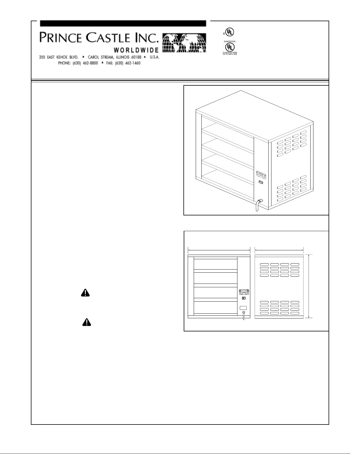
64.5 cm (25-3/8")
47 cm (18-1/2")
64 cm
(25-1/4")
Prince Castle food holding bins provide the capacity
required for large foodservice operations while performing at peak energy efficiency. Each unit features two
individually controlled holding chambers. New Reli-ATemp ™ infrared heater technology holds product
temperatures more consistent within the designated
holding time than other types of heating systems. This
exclusive heater design spreads the heat evenly over the
entire food holding area, eliminating edge drop off.
Food is kept at the desired serving temperature.
This manual provides information for the installation and
safe operation of the unit. Read all the instructions
before attempting to install or operate the unit.
OPERATING
INSTRUCTIONS
DHB4PT-25ACE Holding Bin
UPR
HTR
PROG
LWR
H
T
R
F
ACTUAL
HEAT
TEMP
C
PRINCE
CASTLE
SET
POINT
The model and serial number are located on the identification plate affixed to the unit. Have the information
ready when calling Prince Castle for service or information regarding your unit. You may contact the factory for
assistance at the numbers listed at the top of this page.
Safety Information
IMPORT ANT: The following words and symbols
appear throughout this manual and designate important safety instructions. Read all safety instructions
to avoid personal injury or death, and to avoid
damage to the unit or property.
WARNING
The word WARNING means there is the possibility of
serious injury or death to yourself or others.
CAUTION
The word CAUTION means there is the possibility of
damage to the unit or property.
Electrical Specifications
Figure 1. Pizza Holding Bin
Figure 2. Dimensions
NOTE: Prince Castle reserves the right to change
specifications and product design without notice and
without incurring any obligation to institute such
changes to previously purchased equipment.
Model No. Volts HZ Watts Amps
DHB4PT 220-240V 50 1850 7.6
Prince Castle © 2001 549-501
1
Page 2
Installation & Operation
WARNING
Some exterior surface of the unit get hot. Avoid
touching these surfaces to avoid injury.
CAUTION
For safe and proper operation, the unit must be
located a reasonable distance from combustible
walls and materials. If safe distances are not
maintained, discoloration or combustion could
occur. Locate the unit on a level surface strong
enough to support the weight of the unit.
Temperature Control Panel
All electrical connections must be in accordance
with local electrical codes and any other applicable codes. Connections should be made by a
qualified, licensed electrician.
1. Remove the unit from the box and remove all
protective packaging.
2. Place the unit on a counter and seal it’s base to
the counter with food-approved sealant.
3. Insert the power cord plug into the electrical
outlet.
NOTE: The electrical outlet should be a dedicated
line.
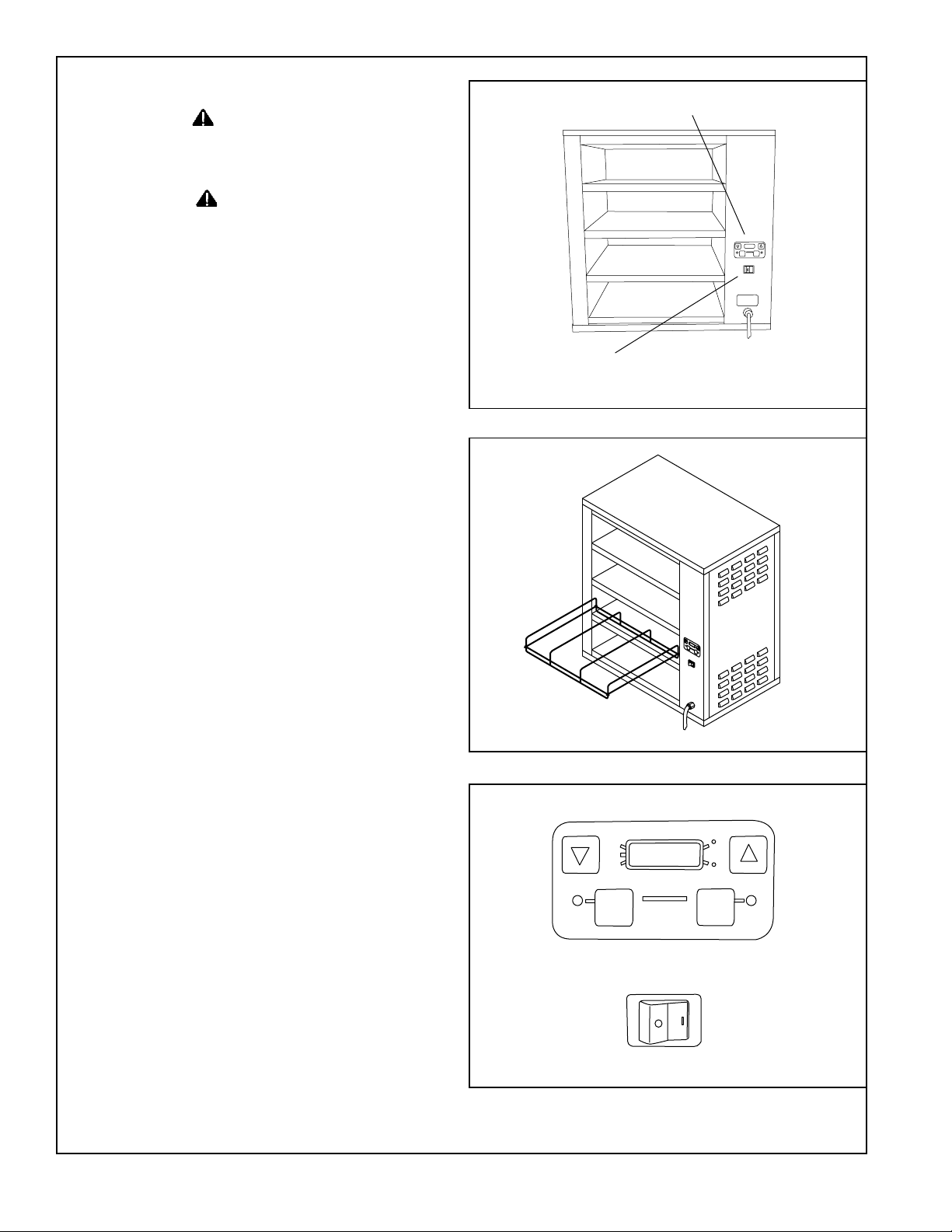
4. Install the sandwich rack into one of the cavity
locations (Figure 3).
5. Turn the power switch on (Figure 3). Allow 30
minutes for warm-up.
T emperature Control Panel
NOTE: The unit has four heating cavites: A, b, C, d
and each cavity is equipped with both an upper and
lower heating element. Each element can be set with
it’s own temperature using the temperature control
panel. See PROGRAMMING THE UNIT on the next
page.
The temperature control panel has the following buttons
and displays (Figure 5).
On/Off Power Switch
Figure 3. Parts Identification
Figure 4. Installing Rack
UPR
HTR
PROG
LWR
HTR
ACTUAL
TEMP
PRINCE
CASTLE
HEAT
U
PR
HTR
P
ROG
L
W
R
HT
R
ACTUAL
TEMP
PRINCE
CASTLE
F
H
EA
T
C
SET
POINT
F
C
SET
POINT
Arrow Up/Down: When in the Operating Mode, use
these buttons to scroll up or down through the four
heater cavities to display actual or setpoint temperature.
Actual T emp: Pressing this button displays the actual
heating temperature for the indicated heating cavity .
Setpoint: Pressing this button displays the setpoint
temperature for the indicated heating cavity .
Prince Castle © 2001 549-501
2
Figure 5. Temperature Control Panel
Page 3

Message Display: The window has a four-digit display
ACTUAL
TEMP
SET
POINT
PRINCE
CASTLE
HEAT
UPR
HTR
HTR
LWR
PROG
F
C
A 99
o
Press to
Decrease
Press to
Increase
for showing numerical values for actual and setpoint
temperatures. LED indicators are also displayed to
indicate the when temperature is displayed for the upper
heater (UPR HTR), program mode (PROG) and lower
heater (LWR HTR). The letters A, b, C, d are also
displayed to indicate the appropriate heating cavity .
PRINCE CASTLE: Pressing this button along with the
SETPOINT button enables programming of the individual
heating elements.
Programming the Unit
UPR
HTR
PROG
LWR
HTR
ACTUAL
TEMP
A 93
HEAT
PRINCE
CASTLE
o
POINT
F
C
SET
RUN MODE
NOTE: The factory default temperature settings are
displayed in Celsius (figure 6). To switch to Fahrenheit,
turn the power switch to OFF. Press and hold the UP
arrow button, then turn the power switch to the ON
position. After two seconds, release the UP arrow
button. To return to Celsius, turn the power switch to
OFF. Press and hold the DOWN arrow button and turn
the power switch to ON. After two seconds, release
the DOWN arrow button.
1. To view the actual temperatue of a heater, press
the UP or DOWN Arrow button until the desired
heating cavity (A, b, C, d) and heating element
(UPR HTR or LWR HTR) is displayed.
2. Presss the ACTUAL TEMP button to view the
temperature.
PROGRAM MODE
The temperature adjustment range for any heater is OFF
and 65° – 107°C (150° – 225°F). The recommended
starting setpoint is 93°C (200°F) for all heaters.
Figure 6. Run Mode
UPR
HTR
PROG
LWR
HTR
ACTUAL
TEMP
PRINCE
A 93
HEAT
CASTLE
o
Step 1
UPR
HTR
PROG
LWR
HTR
ACTUAL
TEMP
A 93
HEAT
PRINCE
CASTLE
o
Step 2
F
C
SET
POINT
F
C
SET
POINT
NOTE: These temperatures may be increased or
decreased as long as the quality is maintained as well
as the desired temperature of the food product.
Step 3
T o change a heater setpoint, use the following procedure (Figure 7):
1. Press and release the UP or DOWN Arrow button
until the desired heater cavity is selected.
2. Press and hold the SETPOINT button, then press
UPR
HTR
PROG
LWR
HTR
ACTUAL
TEMP
A 99
PRINCE
CASTLE
HEAT
o
F
C
SET
POINT
the PRINCE CASTLE button for 6 seconds. The
LED indicator next to PROG will light to indicate the
Step 4
Program mode is active.
3. Use the UP or DOWN Arrow buttons to increase or
Figure 7. Program Mode
decrease the desired setpoint temperature.
Prince Castle © 2001 549-501
4. Press the SETPOINT button to store the setpoint
temperature and to exit the Program Mode. The
LED nest to PROG will turn off and the controller
will regulate the new setpoint temperature.
3
Page 4

Cleaning
WARNING
Always turn the power switch to OFF, allow the
unit to cool down and unplug the power cord
from the electrical outlet before performing any
maintenance on the unit.
CAUTION
This unit is not waterproof. Do not clean with
water jet or jet spray. Do not immerse the unit in
water.
The use of abrasive cleaners or ice water could
scratch or damage the unit.
1. Turn the unit of f and allow to cool down (approximately 25 minutes).
2. Unplug the power cord from the electrical outlet.
3. Wipe down surfaces with a damp cloth. Do not use
abrasive cleaners, unapproved cleaner or ice
CAUTION
Troubleshooting
Problem Cause Solution
Display flashes Open relay. Replace Power Circuit Board
“Opn” & “rEL” Circuit inoperable
Display flashes Shorted relay. Replace Power Circuit Board.
“SHr” & “rEL” Circuit inoperable.
Open heater. Test heater resistance.(150.2 Ohms)
Display shows “LLL” T emperature is below 75° F Normal display during warm up.
Heater inoperable. Test heater resistance.(150.2 Ohms)
Probe inoperable. Check for open thermocouple wires from
Relay Inoperable probe. Replace heater/probe assembly .
Display shows “HHH” for Temperature is above300° F Diagnostic circuit inoperable. Replace
an extended period of time (abnormal operation) Power Circuit Board.See B above.
assembly .
To reset all times and temperatures to the factory settings, turn unit off, press and hold the UP and DOWN
ARROW BUTTONS at the same time, turn unit back on. A “P” will appear in the display and all times and
temperatures will be reset to the original factory settings.
Prince Castle © 2001 549-501
4
Page 5

Exploded View & Parts List
1
2
Item Part Description
1 549-047S Upper Heater Assy.
2 549-046S Lower Heater Assy.
3 549-044 Pizza Rack
4 78-166S Rocker Switch, On/Off
5 545-046S PCB Display
6 545-047S PCB Control
7 72-232S Power Cord
3
7
Wiring Diagram
6
5
4
Prince Castle © 2001 549-501
5
Page 6

Limited Warranty
This product is warranted to be free from defects in material and/or workmanship for a period of two (2)
years from date of original installation not to exceed 30 months from date of shipment from our factory.
P.C. Boards and Heaters are warranted for three (3) years from date of installation, not to exceed 42
months from date of shipment from our factory.
This warranty covers on-location service (i.e., trip charges and/or mileage).
Travel mileage is limited to 100 miles (160 kilometers) round trip (one trip per warranty) from an
authorized service agency or its sub-service agency.
Any component which proves to be faulty in material and/or workmanship will be replaced or repaired
(at the option of Prince Castle, Inc.) without cost to the customer for parts or labor.
This warranty is subject to the following exceptions/conditions:
! Any use of non-genuine Prince Castle spare parts voids this warranty.
! All labor shall be performed by an authorized Prince Castle Service Agent during regular working
hours. Overtime premium will not be covered.
! Damage caused by carelessness, neglect, and/or abuse (e.g., dropping, tampering or altering parts),
equipment damaged in shipment, by fire, flood or an act of God is not covered under this warranty.
Prince Castle © 2001 549-501
6
 Loading...