

Page 1
OPERATING
INSTRUCTIONS
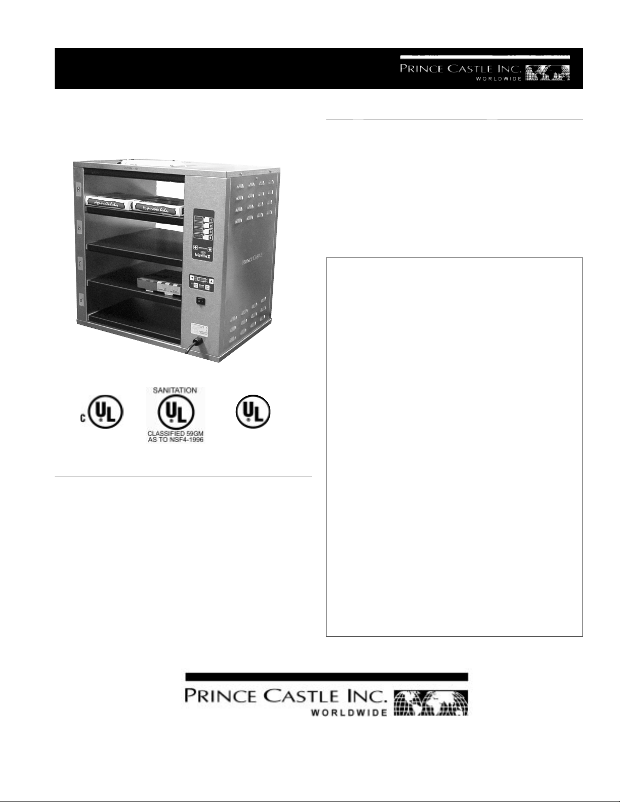
Boxed Pizza Holding Bin
Model No. DHB4PT-25
ELECTRICAL SPECIFICATION
Model Volts Hz Watts Amps
DHB4PT-25 120 60 1700 14.2
DHB4PT-25J 200 50/60 1700 8.5
DHB4PT-25CE 220-240 50 1850 7.7
TABLE OF CONTENTS PAGE
Installation..................................................................... 2
Operating ....................................................................... 2
Cleaning ........................................................................ 3
Exploded View .............................................................. 4
Parts List....................................................................... 4
Troubleshooting Guide ................................................. 5
Wiring Diagram ............................................................. 6
LIMITED WARRANTY
This product is warranted to be free from defects in
material and/or workmanship for a period of two (2) years
from date of original installation (with the exception of
racks, pans, and covers), not to exceed 30 months from
date of shipment from our factory. P.C. Boards and
Heater Assemblies are warranted for three (3) years from
date of installation, not to exceed 42 months from date
of shipment.
Any component which proves to be faulty in material and/
or workmanship will be replaced or repaired (at the option
of Prince Castle, Inc.) without cost to the customer for
parts or labor. This warranty covers on location service
(i.e. trip charges and/or mileage). Travel mileage is
limited to 100 miles (200 kilometers) round trip (one trip
warranty) from an authorized service agency or its subservice agency.
This warranty is subject to the following exceptions/
conditions:
z Use of any non-genuine Prince Castle parts voids this
warranty.
z All labor shall be performed during regular work hours.
Overtime premium will be charged to the buyer.
DHB4PT-25GB 220-240 50 1850 7.7
355 East Kehoe Blvd. ! Carol Stream, IL 60188
Printed in 2001
Prince Castle Inc.
Tel: (630) 462-8800 ! Fax: (630) 462-1460
Toll Free: 1-800-PCASTLE
z Damage caused by carelessness, neglect, and/or
abuse (e.g., dropping, tampering or altering parts,
equipment damaged in shipment, by fire, flood or an
act of God) is not covered under this warranty.
549-503revA
Page 2
INSTALLATION
1. After you have removed the unit from the carton,
inspect the unit for signs of damage. If there is
damage to the unit:
! Notify carrier within 24 hours after delivery.
! Save carton and packing materials for inspection
purposes.
! Contact the Prince Castle Customer Sales
Department at 1630-462-8800 to arrange for
a replacement to be sent.
1. Place the bin on a counter and seal its base to
the counter with food-approved sealant.
2. Insert the power cord into a proper voltage
receptacle. Note: This should be a dedicated
outlet. No other equipment should be operating
on this line (i.e. fryers, refrigerators, etc.)
• ACTUAL TEMP: The actual temperature is
displayed for the selected heaters when this
button is pressed during the operating mode
and the ACTUAL LED indicator will be on.
• UP ARROW and DOWN ARROW: When
pressed in the operating mode, will scroll
through the upper and lower heaters for all
four cavities to display either the actual or
set point temperature. The LED next to the
UPPER SHELF or LOWER SHELF will be on
to indicate which heater is being selected.
The letters A, b, C, and d are displayed to
show the selected cavity location for the
upper and lower heaters.
When reading the digital display from left-to-right,
the following information is displayed: The Upper or
Lower heater for the selected cavity (A, b,C,or d)
if power is being applied to the heater, and if the
display temperature is the ACTUAL or SET-POINT
temperature.
3. Turn the power switch on. Allow 30 minutes for
warm-up.
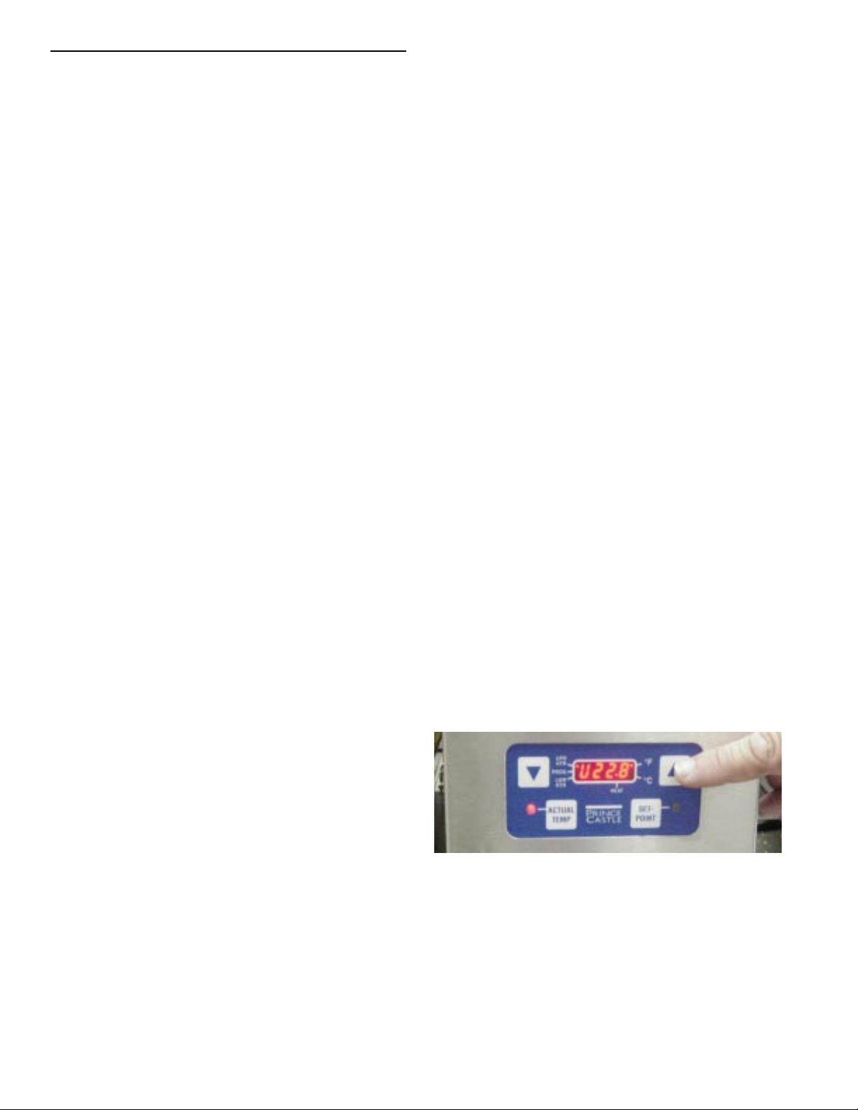
THE TEMPERATURE CONTROL
PANEL
1. Indicators and Displays
Within the four character digital display there are
LED indicators. The four character digital display shows the numerical value of the temperature, and the LED indicators display the following:
• The LED indicator next to the UPR HTR (for
the UPPER HEATER) is on when the tem-
perature being displayed is for the upper
heater.
• The LED indicator next to the PROG is on
when in the Program Mode.
• The LED indicator next to the LWR HTR for
the LOWER HEATER) is on when the tem-
perature being displayed is for the lower
heater.
• The LED indicator next to the HEAT is on
when power is applied to the selected heater.
PROGRAMMING
The temperature adjustment range for a heater zone
is: OFF, 150°F to 275°F. The recommended starting
setpoint temperature for all four heaters is 180°F.
Use the following procedure to change a setpoint
temperature.
1. Press the UP or DOWN arrow button until
the heater to be changed is selected. For
Top Cavity, the LED next to the UPR CAV is
on, and for lower cavity, the LED next to the
LWR CAV is on. After selecting the cavity,
the left most character in the temperature
display shows the heater. U is the Upper
heater and L is the Lower heater.
2. Control Panel buttons and LED indicators
• SET POINT: The set-point temperature is
displayed for the selected heaters when this
button is pressed during the operating mode.
The SET POINT LED indicator will be on
when the Set-point mode is selected. Press
and hold the Prince Castle button then press
and hold the SET-POINT button to program
the temperature for the selected heater.
2
Page 3
2. To change the temperature of the selected
zone, press and hold the SET POINT button
and press the PRINCE CASTLE button for 6
seconds. The LED indicator next to PROG
will light to indicate the Program Mode is
active.
3. Use the UP and DOWN arrow buttons to
increase or decrease the setpoint temperature.
1. Press the timer button, the display changes
from —:— to –5—. The character 5 will be
flashing. Press the up arrow button two
time. The display will change to -7—.
2. Press the Prince Castle logo button. The
display now changes to -75-, and the character 5 is flashing. Press the down arrow
twice to change the flashing character to 3.
Press the Prince Castle logo button to
complete the ticket number entry sequence.
The display will show -73-.
OPERATION
The temperature value is set to display in Fahrenheit. To change to Celsius, turn the power switches
off. Press and hold the UP arrow then turn the
power switch on and after two seconds, release the
UP arrow button. To change back to Fahrenheit,
turn the power switch to the off position, press and
hold the DOWN arrow and turn the power switch to
the on position. After two seconds, release the
DOWN arrow button.
4. the ACTUAL TEMP button to end the Pro-
gram Mode and store the setpoint temperature Press value (the LED next to PROG will
turn off). The controller will regulate to the
new setpoint temperature.
5. Repeat Steps 1-4 for the rest of the heaters.
PROGRAMMING THE TIMERS
There are two activities that take place when a timer
button is pressed. The first is the count up timer is
started, and the second is the display prompts the
operator to enter the ticket number. If more than
two buttons are active, the display with the oldest
time (the ticket number) will be flashing. When the
customer presents the ticket, the operator presses
the timer button. The display changes to show the
total time that the pizza was in the cavity. After
recording the time, the operator presses the timer
button to reset the timer, the display changes to —
:—. The following describes the sequence to entering the ticket number 73 into the timer.
To view the actual heater temperature, press the
ACTUAL TEMP button. The LED indicator next to
the ACTIVE TEMP button will light. Press the UP or
DOWN arrow button to select the heater.
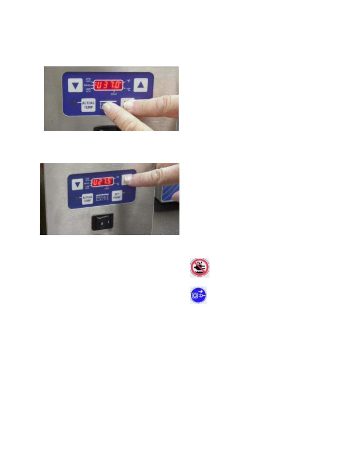
CLEANING
Caution: This bin is not watertight. Do
not clean with Water Jet/Jet Spray. Do
not immerse the bin with water.
Caution: Before unplugging the power
cord, make sure the power switch is in the
OFF position.
1. Unplug the power cord from the outlet.
2. Allow the bin to cool down (approximately 25
minutes).
3. Wipe down surface with a damp cloth. Do not
use a green Scotch Bright pad, unapproved
cleaner, ice or water.
3
Page 4

EXPLODED VIEW
3
4
7
5
2
1
12
13
1
8
11
10
2
9
PARTS LIST
ITEM PART DESCRIPTION
1 72-207S Power Cord
2 549-033 Cover, Side
3 549-031 Cover, Top
4 740-239S PCB, Timer
5 545-046S PCB, Display
6 545-047S Main PCB
(Not Shown)
7 740-028S Overlay & Face Plate (Timer)
8 545-039S Overlay & Face Plate (Main)
9 549-016 Cover, Bottom
10 545-076 Insulation
11 78-166S Lighted Rocker Switch
12 549-006S Upper Heater Assy.
13 549-002S Lower Heater Assy.
4
Page 5

TROUBLESHOOTING
Problem Cause Solution
A. Display flashes Open relay. Replace Power Circuit Board
“Opn” & “rEL” Circuit inoperable
B. Display flashes Shorted relay. Replace Power Circuit Board.
“SHr” & “rEL” Circuit inoperable.
Open heater. Test heater resistance.(150.2
Ohms) Replace Heater
Power and Main Circuit Boards. Verify ribbon cable connection.
C. Display shows “LLL” Temperature is below 75° F Normal display during warm up.
Heater inoperable. Test heater resistance.(150.2 Ohms)
Probe inoperable. Check for open thermocouple wires from
Relay Inoperable probe. Replace heater/probe assembly.
D.Display shows “HHH” for Temperature is above300° F Diagnostic circuit inoperable. Replace
an extended period of time (abnormal operation) Power Circuit Board.See B above.
and heater surface
temperature is hot.
Display shows “HHH” for Probe is inoperable Check for pinched thermocouple
an extended period of time wires from probe. Replace heater/probe
and heater surface assembly.
temperature is cool.
To reset all times and temperatures to the factory settings, turn unit off, press and
hold the UP and DOWN ARROW BUTTONS at the same time, turn unit back on. A “P”
will appear in the display and all times and temperatures will be reset to the original
factory settings.
5
Page 6

WIRING DIAGRAM
6
Page 7

 Loading...