

Page 1
Operation
Product Holding Bin
Manual
DHB2PT-YUM Series
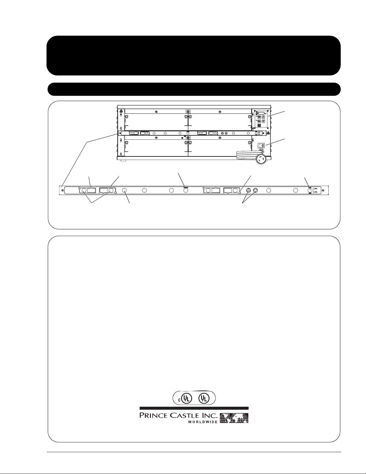
Product Identification
Temperature
Control Panel
Power On/Off
Button Bar
Upper Pan
Displays
Pan Buttons
NOTE: No timer bars on models DHB2PT-33KFCCEN and DHB2PT-46KFCCEN. Four (4) high temperature amber pans 12" x 20" x 2-1/2" and
covers not included.
Lower Pan
Displays
PRINCE CASTLE
LOGO Button
Transfer Button
LED Timers
(tri-color)
UP and DOWN Arrow
Buttons
Switch
MENU/ENTER Button
This product is warranted to be free from defects in material and/or
LIMITED WARRANTY
workmanship for a period of 1 year from date of original installation, not to
exceed 18 months from the date of manufacture.
Any component which proves to be faulty in material and/or workmanship
will be replaced or repaired (at the option of Prince Castle, Inc.) without
cost to the customer for parts and labor. This warranty covers on-location
service (i.e. trip charges and/or mileage). Travel mileage is limited to
100 miles (200 Kilometers) round trip (one trip warranty) from an
authorized service agency or its sub-service agency.
This warranty is subject to the following exceptions/conditions:
• Use of any non-genuine Prince Castle parts voids this warranty.
• All labor to be performed during regular work hours. Overtime premium
(the incremental amount) will be charged to the customer.
• Damage caused by carelessness, neglect and/or abuse (e.g., dropping,
tampering, or altering parts, equipment damaged in shipment, by fire,
flood or an act of God) is not covered under this warranty.
• All problems due to operation at voltages other than that specified on
equipment nameplates are not covered by this warranty. Conversion to
correct voltage is the customer’s responsibility.
• Normal adjustments as outlined in this manual are not covered under
warranty.
• This equipment must be serviced by Prince Castle Authorized Ser vice
Agency or a Prince Castle Service Technician during the warranty
period.
Product Identification . . . . . . . . . . . . . . . . . . . . . . . . . . . . . . . . . . . . . 1
TABLE OF CONTENTS
Safety Information . . . . . . . . . . . . . . . . . . . . . . . . . . . . . . . . . . . . . . . . 2
Electrical Information . . . . . . . . . . . . . . . . . . . . . . . . . . . . . . . . . . . . . 2
Installation . . . . . . . . . . . . . . . . . . . . . . . . . . . . . . . . . . . . . . . . . . . . . . 2
Initial Startup . . . . . . . . . . . . . . . . . . . . . . . . . . . . . . . . . . . . . . . . . . . . 3
Resetting to Factory Defaults . . . . . . . . . . . . . . . . . . . . . . . . . . . . . . . 3
Operation . . . . . . . . . . . . . . . . . . . . . . . . . . . . . . . . . . . . . . . . . . . . . . 3
Time Declination Feature . . . . . . . . . . . . . . . . . . . . . . . . . . . . . . . . . . 4
Cleaning . . . . . . . . . . . . . . . . . . . . . . . . . . . . . . . . . . . . . . . . . . . . . . . 5
Setting Temperature . . . . . . . . . . . . . . . . . . . . . . . . . . . . . . . . . . . . . . 5
Programming for C & D Heaters for Percentage of Power . . . . . . . . . 6
Control Panel . . . . . . . . . . . . . . . . . . . . . . . . . . . . . . . . . . . . . . . . . . . . 7
Programming . . . . . . . . . . . . . . . . . . . . . . . . . . . . . . . . . . . . . . . . . . . . 7
Calibrating Heaters . . . . . . . . . . . . . . . . . . . . . . . . . . . . . . . . . . . . . . . 8
Selecting Regular Menus . . . . . . . . . . . . . . . . . . . . . . . . . . . . . . . . . . . 8
Programming the Menus . . . . . . . . . . . . . . . . . . . . . . . . . . . . . . . . . . . 9
Changing the Hold and Cook-More Times . . . . . . . . . . . . . . . . . . . . . 10
Setting the Alternating Display Interval . . . . . . . . . . . . . . . . . . . . . . . . 10
Changing Product Names . . . . . . . . . . . . . . . . . . . . . . . . . . . . . . . . . . 11
Addendum: Audio . . . . . . . . . . . . . . . . . . . . . . . . . . . . . . . . . . . . . . . . 11
Set Maximum Transfer Time . . . . . . . . . . . . . . . . . . . . . . . . . . . . . . . . 12
Set Volume Level. . . . . . . . . . . . . . . . . . . . . . . . . . . . . . . . . . . . . . . . . 12
CastleNet
Exploded View . . . . . . . . . . . . . . . . . . . . . . . . . . . . . . . . . . . . . . . . . . . 14
Wiring Diagrams . . . . . . . . . . . . . . . . . . . . . . . . . . . . . . . . . . . . . . . . . 15
®
Communications Network . . . . . . . . . . . . . . . . . . . . . . . . . 13
355 East Kehoe Blvd. • Carol Stream, IL 60188 USA
Telephone: 630-462-8800 • Toll Free: 1-800-PCASTLE
Fax: 630-462-1460 • www.princecastle.com
540-517revG-EN Printed in USA 1/08 © 2008
Page 2
Product Holding Bin
DHB2PT-YUM Series
Safety Information
WARNING CAUTION
Indicates information important to the proper operation of the unit.
Failure to observe may result in damage to the equipment and/or
severe bodily injury or death.
Electrical Information
Model Volts Hz Watts Amps Plug Agency
DHB2PT-33WS 208 60 3200 15.4 L6-20P UL / cUL / UL Sanitation
DHB2PT-33KFC 208 60 3200 15.4 L6-20P UL / cUL / UL Sanitation
DHB2PT-46KFC 208 60 4800 23.1 L6-30P UL / cUL / UL Sanitation
DHB2PT-33KFCCE 220-240 50/60 4300 Max. 17.8 Max. IEC309 CE / UL Sanitation
DHB2PT-46KFCCE 220-240 50/60 6400 Max. 26.7 Max. IEC309 CE / UL Sanitation
DHB2PT-33KFCCEL 220-240 50/60 4300 Max. 17.8 Max. CE / UL Sanitation
DHB2PT-46KFCCEL 220-240 50/60 6400 Max. 26.7 Max. CE / UL Sanitation
DHB2PT-33KFCCEN 220-240 50 4300 17.8
DHB2PT-33KFCKT1 208 60 3200 15.4
DHB2PT-33KFCKT2 208 60 3200 15.4
DHB2PT-46KFCCEN 220-240 50 6400 26.7
Indicates information important to the operation of the unit. Failure
to observe may result in damage to the equipment.
Installation
A. Remove the unit from the carton and inspect for signs of damage. If there is damage to the unit:
• notify the carrier within 24 hours of delivery
• save carton and packaging materials for inspection purposes
• contact your local dealer, or if purchased directly, the Prince Castle Sales Department at 800-722-7853 or 1-630-462-8800 to arrange for a
replacement unit.
NOTE: When installing this unit, the ambient temperature at the mounting site should not exceed 100°F (37.8°C).
B. Place the bin on a counter and seal the base to the counter with food-approved sealant.
C. Plug the power cord into the bin and connect the plug into the proper electrical outlet. All connections must be in accordance with local electrical
codes and any other applicable codes.
NOTE: The electrical receptacle should be a dedicated outlet. No other equipment should be operating on the line (refrigerators, fryers, etc.).
D. Turn the power switch to ON. Allow 30 minutes for warm-up.
NOTE: If the unit is to network with other Prince Castle units, a Retro Bun Timer may be connected to any one bin in the chain. Refer to CASTLENET
COMMUNICATIONS NETWORK in this manual.
Prince Castle reserves the right to change specifications and product design without notice. Such revisions do not entitle the buyer to
corresponding changes, improvements, additions or replacements for previously purchased equipment.
Printed in USA 1/08 © 2008 2 540-517revG-EN
Page 3
Initial Startup
Product Holding Bin
DHB2PT-YUM Series
NOTE: During the first few hours of operation, you may notice a faint odor.
This is normal, and the odor disappears after the first few hours of use.
The bin is tested and calibrated at the factory before shipment. However,
due to temperature and climate changes during shipment, the insulation in
bin can absorb moisture. The odor during the first few hours of use is from
the drying out of the insulation (moisture is driven from the insulation’s
binders, a starch-like material).
Resetting to Factory Defaults
To revert all settings back to the original factory defaults (product times on button bars):
1. Turn the unit off.
2. Press and hold both UP and DOWN arrows.
3. Turn the unit back on and wait 5 seconds.
7
4. Release UP and DOWN arrows.
NOTE: All previously saved settings are lost upon resetting the defaults!
Use with caution.
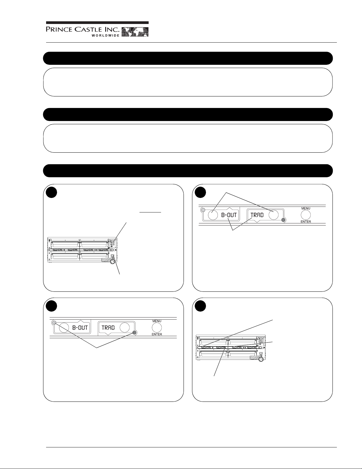
Operation
Turn power On/Off switch to ON position.
1
Allow 30 minutes
heaters to reach operating
temperature. The
Temperature Display will
show temperature as unit
warms up to the operating
temperature.
Power On/Off Switch
for
2
The PAN DISPLAYS will show the
assigned product name.
If no product is assigned, the
display will be blank. Pressing the
PAN button will not activate the
timer if the display is blank.
Pressing PAN button when product
name is displayed will start timing
cycle.
Press PAN Buttons.
LED Timing Status
3
LED Timers
RED (steady) = Ready for product
RED (flashing) = Discard product
GREEN (steady) = Oldest product, use first
GREEN (flashing) = Cook more product
YELLOW (steady) = Newer product, use green first
YELLOW (flashing) = Cook more product
When LED is steady RED, load product and press the PAN
4
button .
If no other pan is active for
a product, the LED for the
first pan loaded will turn
from RED to GREEN.
The LED for the 2nd pan of
the same product (3rd pan,
etc.) loaded will turn from
RED to YELLOW.
An LED timer can be stopped
(cancelled) at any time by
If only one pan is active for a
product, the LED will turn from
RED to GREEN.
pressing and releasing the
corresponding PAN button
quickly 3 times.
540-517revG-EN 3 Printed in USA 1/08 © 2008
Page 4
Product Holding Bin
DHB2PT-YUM Series
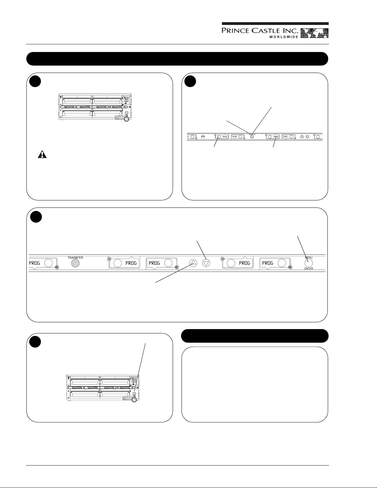
Operation (continued)
When any of the timer LEDs flash, cook more product or
5
remove and discard product as indicated.
GREEN (flashing) = Cook more product
YELLOW (flashing) = Cook more product
RED (flashing) = Discard product
WARNING
Hot surfaces.
To change a menu selection for a specific pan cavity, use the following steps:
7
A. Press and hold the PRINCE CASTLE LOGO button for 6 seconds. All
Pan displays will show PROG. All LED Timers will be RED.
Product, along with any remaining time, can be transferred from
6
one cavity to another as follows:
A. Press and release the
TRANSFER button.
Displays for available bins
are brightly lit. Displays for
bins currently not timing,
are dimly lit.
B. Press and release the PAN
button of the product to be
moved.
NOTE: If product transfer is not completed within a pre-programmed
transfer time, the transfer will be cancelled. See your Manager.
D. Press the UP or DOWN Arrow
button to scroll to the desired
menu item.
C. Move the product. Press and
release the TRANSFER button
again.
D. Press and release the PAN button
for the new location. The new
location will finish timing the
product. When the transferred
pan timing expires and/or is
cancelled, the location will revert
to original menu setting.
E. Press the MENU/ENTER button
to select the menu item.
B. Press and hold the MENU/ENTER button. The display next to the
MENU/ENTER button will display the menu choices. While holding the
MENU/ENTER button, press the UP or DOWN Arrow button to scroll
through the menu choices.
C. Press a PAN button to change its menu. The LED timer will change to
yellow and the display will change from PROG to the assigned menu item.
To shut down the unit, turn the power On/Off switch to OFF.
8
F. Repeat Steps A – E as required for other Pan displays. Press the
PRINCE CASTLE LOGO button to exit the Program Mode.
NOTE: Up to six products may be programmed for each Pan button (1 for
each menu). In addition, a pan may be set as “not used” by assigning “- -- -”
as its product.
Time Declination Feature
To adjust Hold time when starting a timer:
A. Press and hold the timer button.
B. Press the UP or DOWN Arrow button to adjust the Hold time.
NOTE: This adjustment must be done within the first 5 seconds.
NOTE: The range of adjustment cannot be larger than the default hold
time or smaller than the default cook time.
To cancel at any time, press and release the corresponding PAN button
quickly 3 times.
Printed in USA 1/08 © 2008 4 540-517revG-EN
Page 5

Product Holding Bin
DHB2PT-YUM Series
Cleaning
WARNING
Before performing any maintenance, turn the power switch to the OFF position and unplug the power cord from the electrical receptacle.
CAUTION
This unit is not watertight. Do not clean with a water jet/jet spray. Do not immerse the unit in water.
1. Turn the unit off and unplug the power cord from the electrical receptacle.
2. Wipe all parts and unit with a damp cloth. DO NOT use a green Scotch Bright pad cleaner, ice or water.
Setting Temperature
The unit has two shelves, each with an upper and lower heater (four heaters total).
1
Each upper heater has a programmable range of 150° – 350°F (65.6° – 176.7°C).
Each lower heater has a programmable range of 150° – 260°F (65.6° – 126.7°C).
Use the control below and the following steps to set the setpoint temperature for each heater.
This LED will be lit to indicate upper shelf is
selected.
This LED will blink to indicate unit is in Program
Mode.
This LED will be lit to indicate lower shelf is
selected.
Press to display actual temperature for the
selected heater. LED will be lit and actual
temperature is displayed.
Press to display setpoint temperature of a
selected heater. LED will be lit and setpoint
temperature is displayed.
NOTE: To reset all times and temperatures to the factory settings, turn the unit off, then press and hold the UP and DOWN Arrow buttons simultaneously
while turning the unit back on. A “P” will appear in the display and all times and temperatures will be reset to original factory settings.
UPPER SHELF LED
PROG LED
LOWER SHELF LED
ACTUAL TEMP BUTTON and LED
SETPOINT BUTTON and LED
NOTE: The unit is preset to display temperature
in Fahrenheit. To display in Celsius, press and
hold the DOWN Arrow button immediately after
turning on the power switch. To switch back to
Fahrenheit, press and hold the UP Arrow button
immediately after turning on the power switch.
Used with other buttons to scroll through heater
and temperature selections.
Press to program temperature selections.
TEMPERATURE DISPLAY
UP/DOWN ARROW BUTTONS
PRINCE CASTLE LOGO BUTTON
540-517revG-EN 5 Printed in USA 1/08 © 2008
Page 6

Product Holding Bin
DHB2PT-YUM Series
Programming for C & D Heaters for Percentage of Power
33" Heater — C & D Heaters Are Rope Heaters (All Rope Heaters Are Designated for Bottom Heat Only)
AB
D
Upper
Shelf
Lower
Shelf
C
C
46" Heater — D Heaters Are Rope Heaters (All Rope Heaters Are Designated for Bottom Heat Only)
ABC
D
D
D
D
Printed in USA 1/08 © 2008 6 540-517revG-EN
Page 7

Control Panel
Product Holding Bin
DHB2PT-YUM Series
1
• The red indicator light next to the UPPER SHELF label indicates that the temperature being
displayed is for the selected cavity.
• The red indicator light next to the PROG label blinks when in the Programming Mode.
• The red indicator light next to the LOWER SHELF label indicates that the temperature
being displayed is for the selected cavity.
• The red indicator light next to the HEAT label is on when power is applied to the heater zone
being displayed on the control panel.
• The red indicator light next to ACTUAL TEMP label is on when the Actual Temperature is
being displayed for the heater zone being displayed on the control panel.
• The red indicator light next to SET-POINT TEMP label is on when the Set-Point
Temperature is being displayed for the heater zone being displayed on the control panel.
• The digital display shows the shelf and the associated temperature for each heater, for
example:
The display for the upper shelf may show A235 for the UPPER HEATER.
2
• SET-POINT: The Set-Point temperature is displayed for the selected
heaters when this button is pressed during the operating mode. The
SET-POINT indicator light is on when the Set-point mode is selected.
• To Program a heater, press and hold the PRINCE CASTLE button then
press and hold the SET-POINT button for 5 seconds or until the PROG
indicator light turns on. Use the UP and DOWN arrows to change the
Set-Point temperature.
Displays and Indicators
Control Panel Buttons
• ACTUAL TEMP: The Actual Heater temperature is displayed only for
the selected heater when this button is pressed in the operating mode.
• UP ARROW & DOWN ARROW: When pressed in the operating mode,
selects which heater is in the display on the control panel. The indicator
light next to the UPPER SHELF or LOWER SHELF is on to indicate
which shelf is selected.
Control Panel
Programming
1
The temperature of the Upper Heaters can be adjusted from 150 to 350°F
(65.6 to 176.7°C) in one-degree increments (Fahrenheit).
1. Use the UP or DOWN arrow buttons to select Heater A through D in
UPPER or LOWER SHELF.
2. Press the SET-POINT button. When the SET-POINT indicator light is
on, the digital display shows the Set-Point temperature.
Upper/Ceiling Heaters in Both Shelves — Programmed for Temperature
Repeat steps 1 – 5 for other
Heaters in both upper and
lower shelves.
3. To change the temperature setting, press and hold the PRINCE
CASTLE LOGO button; then press and hold the SET-POINT button.
Hold both buttons until the PROG indicator light turns on.
4. Use the UP and DOWN arrow buttons to change the temperature.
5. Press the PRINCE CASTLE LOGO button to store the new value and
to exit the PROGRAMMING mode.
540-517revG-EN 7 Printed in USA 1/08 © 2008
Page 8

Product Holding Bin
DHB2PT-YUM Series
Calibrating Heaters
Use the following steps to calibrate the individual heaters.
1
NOTE: Allow sufficient amount
of time for temperatures to
stabilize before starting
calibration.
Press the UP or DOWN Arrow
button until the desired heater
and upper or lower shelf is
selected.
A. Press and hold the PRINCE CASTLE LOGO and ACTUAL
3
TEMP buttons for 5 seconds. The colon (:) LED indicator will
light. The temperature displayed is the actual heater
temperature sensed by the controller.
B. To clear any offset readings, press the SETPOINT button.
AB
Take a temperature reading within the shelf near the center
2
of the heater surface.
Use a stand-alone temperature
meter (not supplied).
Hot surfaces. Use caution
when taking temperature
readings within the shelf.
4
AB
WARNING
A. Press the UP or DOWN Arrow button until the temperature
displayed matches the reading obtained in Step 2.
B. Press the PRINCE CASTLE LOGO button to save the
temperature value and exit the Calibration Mode.
ACTUAL
TEMP
SETPOINT
Selecting Regular Menus
There are six menus available:
1
Menu 1 – 6
Press and hold the MENU/ENTER button, then use the UP or
DOWN Arrow button to scroll through the 6 menus.
When scrolling, menu numbers
appear in this display.
When the desired menu is displayed, release the MENU/
2
ENTER button. The food products for the menu will be
displayed in the upper and lower BUN TRAY displays.
When timers for a different menu are still active, the REG LED
will flash until they are all cancelled.
Printed in USA 1/08 © 2008 8 540-517revG-EN
Page 9

Programming the Menus
Product Holding Bin
DHB2PT-YUM Series
Press and hold the PRINCE CASTLE LOGO button (on the
1
button bar) until all the displays show PROG and the PAN button
LEDs all glow RED.
A. Press the PAN button next to the display to be changed. The
3
LED will change from RED to YELLOW and the display will
change from PROG to the assigned menu item.
B. Press the UP or DOWN Arrow button to scroll to the desired menu
item.
C. Press the MENU/ENTER button to save the selection. All displays
will show PROG.
Press and hold the MENU/ENTER button. The display next to
2
the MENU/ENTER button will show the menu choices. Use the
UP or DOWN Arrow button to scroll through the 6 menus.
Release the MENU/ENTER button when the desired menu is
displayed.
When the MENU/ENTER button is released, all
displays will again show PROG.
A. Repeat Steps 2 and 3 as required.
4
B. Press the PRINCE CASTLE LOGO button to exit the
Program Mode and return to the Run Mode.
NOTE: Up to six items (one for each menu) may be
programmed for each PAN button. A pan may be set as “not
used” by assigning a blank display as its product.
540-517revG-EN 9 Printed in USA 1/08 © 2008
Page 10

Product Holding Bin
DHB2PT-YUM Series
Changing the Hold and Cook-More Times
A. Press and release the MENU/ENTER button to enter the
1
Set Product Time menu. The display will show, for example,
EGGS TIME ENTR.
B. Use the UP or DOWN Arrow button to scroll through the list
of products. When the desired product is displayed, press
the MENU/ENTER button to select it.
NOTE: Holding the UP or DOWN Arrow button for longer than 2 seconds
will cause the product list to automatically scroll up or down.
A. The display will now show current Cook-More time. Use the UP
3
or DOWN Arrow button to scroll to the desired Cook-More time.
B. When the desired Cook-More time is displayed, press the MENU/
ENTER button to save it.
NOTE: Cook-More time cannot be increased to more than the Hold
time minus one minute.
A. The display now shows the current Hold time.
2
B. Use the UP or DOWN Arrow button to scroll to the desired Hold time.
When the desired Hold time is displayed, press the MENU/ENTER
button to save the desired Hold time.
NOTE: Hold time cannot be reduced to less than the Cook-More
time plus one minute.
A. The display will show PROD TIME ENTR. Repeat Steps 2 – 4
4
for any other product.
B. Press and release the PRINCE CASTLE LOGO button at any
time to exit the Program Mode and return to the Run Mode.
NOTE: If the MENU/ENTER button has not been pressed to save
any changes, the program will revert to the original values.
Setting the Alternating Display Interval
A. The Alternating Display Interval allows the timer bar displays to alternate between the product name and remaining Hold time. The default setting
is 5 seconds.
B. Press and hold the PRINCE CASTLE LOGO button, then immediately press and hold the MENU/ENTER button until the display shows one of the
programming menus.
C. Use the UP or DOWN Arrow button to scroll to the DISP ALT TIME menu. Press MENU/ENTER button.
D. Use the UP and DOWN Arrow buttons to adjust the interval setting from 0 to 15 seconds. Press MENU/ENTER to save the change.
E. Press and hold the PRINCE CASTLE LOGO button at any time to exit the Program Mode.
NOTE: Setting the interval to “0” disables the feature and only the product name will be displayed.
PRINCE CASTLE LOGO Button MENU/ENTER Button
Printed in USA 1/08 © 2008 10 540-517revG-EN
Page 11

Product Holding Bin
DHB2PT-YUM Series
Changing Product Names
A. The EDIT PRODUCT NAME menu is used to change a default product name to one of your own choosing.
1
B. Press and hold the PRINCE CASTLE LOGO button, then immediately press and hold the MENU/ENTER button until the display shows one
of the programming menus.
C. Use the UP or DOWN Arrow button to scroll to the PROD NAME
PRINCE CASTLE LOGO Button MENU/ENTER Button
ENTR menu.
A. Press and release the MENU/ENTER button to enter the EDIT
2
PRODUCT NAME menu.
The display will read PROD XXXX
B. Use the UP or DOWN Arrow button to scroll through the list of
products.
C. When the desired product is displayed, press the MENU/
ENTER button to select it. The first letter (in this case, the E )
will start blinking.
When all four digits have been changed, press the MENU/
4
ENTER button to save the new name.
ENTR.
A. To change the blinking E, use the UP or DOWN Arrow button to
3
scroll to the desired letter/number/symbol.
B. When the desired selection is displayed, press the PAN button
(to the left or right of the selected display) to move to the next
digit.
C. Repeat for all digits.
NOTE: Holding the UP or DOWN Arrow button for longer than 2 seconds
will cause the selected digit to automatically scroll up or down.
A. The display will show PROD NAME ENTR. Repeat Steps 2 – 4
5
for any other product.
B. Press and release the PRINCE CASTLE LOGO button at any
time to exit the Program Mode and return to the Run Mode.
NOTE: If the MENU/ENTER button has not been pressed to save
any changes, the program will revert to the original names.
Addendum: Audio
1. When a PAN button is pressed to activate a timer, the unit will sound a tone.
2. When the timer reaches the “Cook-More” time, an alarm will sound for 5 seconds.
3. When the timer has counted down completely, an alarm will sound continuously until it is manually shut off by pressing the appropriate pan button.
The product in that pan should be discarded at this time.
540-517revG-EN 11 Printed in USA 1/08 © 2008
Audio Capabilities
Page 12

Product Holding Bin
DHB2PT-YUM Series
A. The SET MAXIMUM TRANSFER TIME menu is used to set the amount of time allowed to make a product transfer from one pan to another.
1
B. Press and hold the PRINCE CASTLE LOGO button, then immediately press and hold the MENU/ENTER button until the display shows one of
the programming menus.
C. Use the UP or DOWN Arrow button to scroll to the XFR TIME
PRINCE CASTLE LOGO Button MENU/ENTER Button
Set Maximum Transfer Time
ENTR menu. (NOTE: Units with 6 or 8 pan displays will show MAX XFR TIME ENTR.)
A. Press and release the MENU/ENTER button to enter the SET
2
MAXIMUM TRANSFER TIME menu.
B. The display shows XFR :20
seconds.
ENTR. This shows a value of 20
A. To change the time, use the UP or DOWN Arrow button to
3
scroll to the desired time. When the desired selection is
displayed, press the MENU/ENTER button to enter the
selection.
B. Press and release the PRINCE CASTLE LOGO button at any
time to exit the Program Mode and return to the Run Mode.
NOTE: If the MENU/ENTER button has not been pressed to save
any changes, the program will revert to the original time.
Set Volume Level
A. The default setting for the volume level is OFF.
1
B. Press and hold the PRINCE CASTLE LOGO button, then immediately press and hold the MENU/ENTER button until the display shows one
of the programming menus.
C. Use the UP or DOWN Arrow button to scroll to the Set Vol 0
PRINCE CASTLE LOGO Button MENU/ENTER Button
ENTR menu.
A. Press and release the MENU/ENTER button to enter the Set
2
Volume menu.
B. The display shows SET VOL 0
volume is currently turned off.
The volume may be set for Vol 0 (off) or for volume levels Vol 1
through Vol 3.
ENTR. This shows that the
A. To change the volume level, use the UP or DOWN Arrow
3
button to scroll to the desired level. When the desired
selection is displayed, press the MENU/ENTER button.
B. Press and release the PRINCE CASTLE LOGO button at any
time to exit the Program Mode and return to the Run Mode.
NOTE: If the MENU/ENTER button has not been pressed to save
any changes, the program will revert to the original volume level.
Printed in USA 1/08 © 2008 12 540-517revG-EN
Page 13

CastleNet® Communications Network
Product Holding Bin
DHB2PT-YUM Series
The Prince Castle DHB Bins, external timers, and New Bun Cabinet
Timers can be inter-connected to form the CastleNet
Network. The network can be used for data transfer between bins and
timers for menu updates or to transfer product hold time from bin-tobin. A PDA (or similar device) or a notebook with Prince Castle
MenuView
desired changes.
Each bin is supplied with a standard 25' cable and allows units to be
“daisy-chained” together to form the network. If cable is too short, use
Prince Castle Extender Cable Kit, P/N PC-COMEXT.
The factory default address for Main bins and timers is address 1. The
factory default address for Specialty bins and timers is address 2. If a
third bin is used, the address must be set at 3.
2
®
software is used to connect to the network and enter the
IMPORTANT: Each timer must have a different address. If a
location has three bins, it is recommended that the bins and
timers be set consecutively to addresses 1 through 3.
BIN 1 BIN 2 BIN 3
Example
®
Communication
Telephone jack plugs are located on the back of the unit. Connect
1
the units using the cables provided as shown here.
BIN 1
A Turn the power switch off, wait 15 seconds. Turn the switch to
3
ON while pressing and holding the ACTUAL TEMP and SETPOINT buttons. The display will show the current bin address.
B. Continue to hold the buttons until PROG LED turns on.
A
BIN 2 BIN 3
Example
B
Use the UP or DOWN Arrow button to scroll to the desired
4
address. Press the PRINCE CASTLE LOGO button to store the
new address.
Available addresses are:
BIN
1 thru BIN9, BINA, BINB, BINC, BIND,
E and BINF.
BIN
IMPORTANT: Continue to Step 5 to
check the timer address. No two
timers can have the same address.
To change the timer address, turn the unit power switch off and
6
wait 15 seconds. Turn the power switch back on and immediately
press and hold the PRINCE CASTLE LOGO button and the
DOWN Arrow button for approximately 6 seconds or until the
display shows ADDR
The address number will blink on/off.
entr BAR 2.
To check the timer address, press and hold the PRINCE CASTLE
5
LOGO button and the DOWN Arrow button. The current timer
address will be displayed in the far right timer display.
To change the timer address, proceed to Step 6.
Use the UP or DOWN Arrow button to scroll to the desired
7
address. Press the MENU/ENTER button to store the new
address and return to normal Operating Mode.
Available addresses are:
BAR 1 thru BAR 9, BAR A, BAR B, BAR C, BAR D, BAR E and BAR F.
540-517revG-EN 13 Printed in USA 1/08 © 2008
Page 14

Product Holding Bin
DHB2PT-YUM Series
1
12
Exploded View
1
2
11
5
3
Model DHB2PT-33KFC, 33WS, 33KFCCE, 33KFCCEL and 33CEN
Ref. No. Description
1 540-640S Upper Heater
2 540-485S Upper Shelf, Lower Rope Heater
3 72-428S Power Cord Assy. (33KFC) (33WS)
3 72-426S Power Cord Assy. (33KFCCE) (33KFCCEN)
3 72-433S Power Cord Assy. (33KFCCEL)
4 540-467S Base (Rope Heater)
5 Not Applicable
6 Not Applicable
7 78-184S Power Switch
8 88-709-2-11S Speaker Assy.
9 740-650S PCB Audio Interface
10 541-1042S Main PCB (33KFC)
10 541-1079S Main PCB (33KFCCE) (33KFCCEN)
10 541-1137S Main PCB (33KFCCEL)
10 541-1073S Main PCB (33WS)
11 541-719S Display PCB
12 541-1100S Timer Bar, 8CH, Main (33KFC)
12 541-1067S Timer Bar, 8CH, Main (33WS)
12 541-1075S Timer Bar, 8CH, Main (33KFCCE)
12 541-1160S Timer Bar, 8CH, Main (33KFCCEL)
* 541-1101S Timer Bar, 8CH, Aux (33KFC)
* 541-1076S Timer Bar, 8CH, Aux (33KFCCE)
* 541-1161S Timer Bar, 8CH, Aux (33KFCCEL)
* 197-232S Rubber Feet (Pkg of 4)
* 536-802S Overlay, Display
*Part not shown
(No Aux for 33WS)
1
9
4
8
7
Model DHB2PT-46KFC, 46KFCCE, 46KFCCEL and 46CEN
Ref. No. Description
1 540-647S Upper Heater
2 540-492S Upper Shelf Rope Heater
3 72-356S Power Cord Assy. (46KFC)
3 72-426S Power Cord Assy. (46KFCCE) (46KFCCEN)
3 72-433S Power Cord Assy. (46KFCCEL)
4 540-484S Base (Rope Heater)
5 65-058S Relay, SSD
6 65-063-06S Relay, Mechanical
7 78-184S Power Switch
8 88-709-2-11S Speaker Assy.
9 740-650S PCB Audio Interface
10 541-1043S Main PCB (46KFC)
10 541-1080S Main PCB (46KFCCE) (46KFCCEN)
10 541-1139S Main PCB (46KFCCEL)
11 541-719S Display PCB
12 541-1102S Timer Bar, 12CH, Main (46KFC)
12 541-1077S Timer Bar, 12CH, Main (46KFCCE)
12 541-1049S Timer Bar, 12CH, Main (46KFCCEL)
* 540-721S Single Cover Retainer Kit (All Models)
* 540-727S Dual Cover Retainer Kit (All Models)
* 540-758S 1/2 Pan Metal Cover Kit (Pkg of 2) (All Models)
* 540-691S Full Size Metal Cover Kit (Pkg of 2) (All Models)
* 540-461S Divider, No Lid (All Models)
* 541-1103S Timer Bar, 12CH, Aux (46KFC)
* 541-1078S Timer Bar, 12CH, Aux (46KFCCE)
* 541-1050S Timer Bar, 12CH, Aux (46KFCCEL)
* 66-045S Strain Relief
* 197-232S Rubber Feet (Pkg of 4)
* 536-802S Overlay, Display
* 540-753S Kit, Side Guide (L & R)
6
10
Printed in USA 1/08 © 2008 14 540-517revG-EN
Page 15

Model DHB2PT-33KFC Series
1
Product Holding Bin
DHB2PT-YUM Series
Wiring Diagrams
540-517revG-EN 15 Printed in USA 1/08 © 2008
Page 16

Product Holding Bin
DHB2PT-YUM Series
Model DHB2PT-46KFC Series
1
Wiring Diagrams (Continued)
Printed in USA 1/08 © 2008
Prince Castle Inc.
355 East Kehoe Blvd. • Carol Stream, IL 60188 USA
Telephone: 630-462-8800 • Fax: 630-462-1460
Toll Free: 1-800-PCASTLE
www.princecastle.com
 Loading...