

InstructionSheet
InstructionSheet
TANT SAFETY INFORMATION. READ AND FOLLOW ALL SAFETY INSTRUCTIONS. Follow label information
IMPOR
and instructions concerning W
and proper lamping. Do not install in areas subject to combustible vapors or gases. Before wiring to power supply and
during servicing or relamping, turn of
qualified service personnel. Product must be grounded to avoid potential electric shock or other potential hazard.
Product must be mounted in locations and at heights and in a manner consistent with its intended use, and in
compliance with the National Electrical Code and local codes. The use of accessory equipment not recommended by
the manufacturer or installed contrary to instructions may cause an unsafe condition. Do not block light emanating from
product in whole or part, as this may cause an unsafe condition. Do not allow items such as drapes, curtains, screens or
the like to come into contact with the product or to block light from the product, as this may cause an unsafe condition.
INSTALLATION INSTRUCTIONS
Mate-N-Lock
Connectors
Part No. . . . . . . . . . . . . . . . . . . . . . . . . . . . . . . . .05064500
et or Damp Locations, installation near combustible materials, insulation, building materials,
f power at fuse or circuit breaker.
All servicing or relamping must be performed by
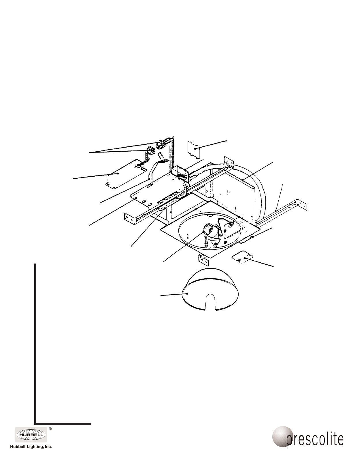
RECESSED H.I.D.
J-Box Cover
(removed for clarity)
J-Box
Housing
www.prescolite.com • Prescolite TollFree Technical Support 1.888.PRS.4TEC • Hours: 8am - 5pm ET
FE Ballast
Ballast Retaining
Strap
Mounting Bracket
Hanger
Bracket
Socket
Assembly
Reflector
CAUTION: To avoid electrical shock, be sure power supply is turned off before installing or servicing this fixture. Check
1. Install the fixture in the ceiling (see back) using bar hangers placed in the hanger brackets as shown.
2. Adjust the fixture so the bottom of the plaster flange is flush with the finished ceiling line. Accomplish this with the adjustment
3. Remove J-Box cover plate. Remove appropriate knockout and assemble appropriate connector for the supply wire used. Connect
4.
ballast for correct wattage, voltage and lamp type.
mounted in such a manner so that the weight of the fixture is supported by the bar hangers and/or hanger wires secured to the
building structure.
screws securing the hanger brackets on either end of the fixture.
ground wires to green ground leads. Connect white (common) to white (leads). Connect power supply (line) to black lead(s).
Reinstall J-Box cover.
WARNING: DO NOT pinch wires between J-Box/ballast cover and J-Box. Consult a Qualified Electrician for all other
options that require other wiring configurations.
Install the ballast -
FE Ballast Installation: The ballast and housing are shipped separately, and the housing is factory wired for 277 VAC. If the
supply voltage is 277 V
connector from the thermal protector and reconnect it to the 120V connector. Voltage connectors are identified as follows:
AC - black wire
120 V
AC, no adjustment is required. For supply voltage of 120 V
AC - blue wire
277 V
AC, disconnect the prewired 277 V
B6 Bar Hanger
(supplied by Prescolite)
J-Box
J-Box
Cover
This fixture should be
AC
101 Corporate Drive • Spartanburg, SC 29303
With representatives of
Copyright 2005, 08/05 revision, All Rights Reserved - Printed in U.S.A.
fices in principal cities throughout North
America.

InstructionSheet
Part No. . . . . . . . . . . . . . . . . . . . . . . . . . . . . . . . .05064500
5. Connect the mate-n-lock connector from the ballast to the connector from the fixture. Push all connectors and splices back into the
J-Box.
6. Place the ballast retaining strap into the ‘T’ slot in the bracket as shown. Place the ballast on the bracket so it rests against the side
of the J-Box and one of the ballast mounting holes is positioned over the screw inside the J-Box to prevent ballast movement. Wrap
the retaining strap around the ballast and secure it with the draw latch (see Fig. 5)
CAUTION: Do not attempt to modify or rewire factory-installed wiring on the fixture or ballast. Safety and proper operation of the fixture
FIXTURE INSTALLATION
1. Nail one B6 bar hanger to ceiling joist (Fig. 1), or attach to
2. Assemble other bar hanger to fixture by placing in ‘C’
3. To install fixture, position ‘C’ bracket on fixture over the bar
Suspended Ceiling Support
depend on the integrity of the wiring.
suspended ceiling support member with clamps in Packet
94 (Fig. 2). Standard 1 1/2" carrier channels can be used to
install fixture.
bracket and pry locking tabs on ‘C’ bracket against bar
hanger (Fig. 3).
hanger previously installed in ceiling.
Fig. 1
(Inverted ‘T’ Bar)
4. Attach bar hanger on fixture to ceiling structure.
5. Position fixture and lock in place by prying locking tabs
on ‘C’ bracket against bar hanger (Fig. 3).
6. To adjust fixture for varying ceiling thickness, loosen
screws retaining ‘C’ brackets to fixture, raise or lower as
required, tighten screws (Fig. 4).
7. Make electrical connections (see front).
8. Install correct lamp and trim.
Fig. 5
www.prescolite.com • Prescolite TollFree Technical Support 1.888.PRS.4TEC • Hours: 8am - 5pm ET
NOTE:
Bracket
‘C’
on fixture
‘T’ Slot
Fig. 2
For T-Bar Installation
Packet 94 must be ordered
separtely
Locking Tab
Fig. 3
B6 Bar Hanger Clamp
(Packet 94)
Bar Hanger
Fig. 4
Ballast Retaining Strap:
Remove ballast from carton and position it
on ballast support tray. Fasten it securely
with the draw latch supplied with the ballast.
B6 Bar Hanger Assembly
Assemble the bar hangers by overlapping
the ends of two sections and placing the
tabs on each section into the square hole
in the opposite section.
Slide the sections together so the tabs
engage the slots.
B6 Bar Hanger
Vertical adjustment screw (2).
Loosen, do not remove.
101 Corporate Drive • Spartanburg, SC 29303
With representatives of
Copyright 2005, 08/05 revision, All Rights Reserved - Printed in U.S.A.
fices in principal cities throughout North
America.
 Loading...