


The Power Probe Hook Operations Manual
Thank you for purchasing the Power Probe Hook (PPH).
You now have in your possession the most advanced and reliable Power Probe Circuit Tester in its class.
Technicians who have experienced the Power Probe advantages will find the Hook to be even better. It is a no nonsense electrical circuit tester that is designed to diagnose circuits fast without wasting time fumbling with multiple testers, jumper wires and meters. The PPH provides controlled POWER to your circuit for dynamically testing the full function of electrical components bad grounds and circuit connectivity.
The benefits that come from having the ability to supply POWER to circuits and simultaneously observe AMPS, VOLTS, and RESISTANCE are huge!
The PPH also performs passive measurements for diagnosing sensitive automotive circuits, but CAUTION must be stressed before you press the power switch to activate circuits. Just as a scalpel is designed for a professional surgeon, the PPH is designed for professional technicians.
Enjoy your new found power with the PPH. If you have any questions please go to our website www.powerprobe.com or give us a call: 800-655-3585.
“The Ultimate Circuit Tester”
In 1991 Power Probe emerged from one simple idea: “Make the Ultimate Circuit Tester”
From the very first Power Probe Circuit Tester, it was evident that we had invented something unique. It didn’t take long for the Power Probe to become an industry standard for diagnosing and probing DC electrical circuit.
Year after year we have made improvements to our tools. We listen to our customers and with
Power Probe’s desire to serve the technician, it has guided us to provide information, service and product tools that are a MUST for every mechanic.
890 Mariner Street Brea, California 92821 toll free 800.655.3585 local 714.990.9443 fax 714.990.9478
The Serial Number can also be found on the back of the unit or box.
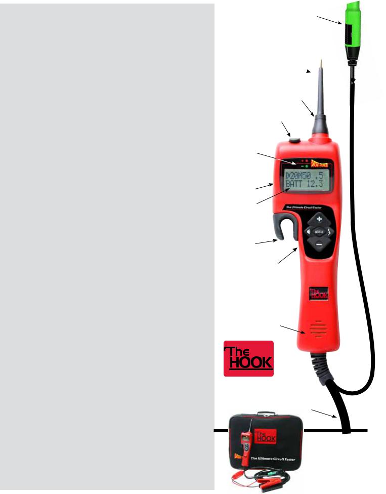
Table of Contents
START-UP................................................................................................................................ |
4-I |
Operating Voltage Source........................................................................................................ |
4-I a |
Connecting to the Vehicle’s Battery (Voltage Source) ............................................................. |
4-I b |
Y-Connector with Battery Clips................................................................................................. |
4-I c |
Auxiliary Ground Lead............................................................................................................. |
4-I d |
Flashlight................................................................................................................................. |
4-I e |
Sleep Mode.............................................................................................................................. |
4-I f |
FIVE BUTTON OPERATIONAL TERMS...................................................................................... |
5-II |
PREFERENCES AND SETTINGS................................................................................................ |
5-III |
Preference Line........................................................................................................................ |
5-III a |
Speaker ON/OFF...................................................................................................................... |
5-III b |
Circuit Breaker Preferences...................................................................................................... |
5-III c |
Power Switch Preferences ....................................................................................................... |
6-III d |
AC Threshold Preferences........................................................................................................ |
6-III e |
LED Voltage Drop Preferences................................................................................................. |
6-III f |
POWER PROBE HOOK MODE (PPHM)..................................................................................... |
7-IV |
Voltage Testing in PPHM:........................................................................................................ |
7-IV a |
Resistance Testing in PPHM:................................................................................................... |
7-IV b |
Activating Electrical Components, Current Draw Testing and Calculated Resistance in PPHM:....... |
8-IV c |
AC Peak to Peak/ Frequency Measuring in PPHM: ................................................................ |
8-IV d |
Hot Shot Testing in PPHM: ..................................................................................................... |
9-IV e |
CONTINUITY and RELAY TESTER............................................................................................. |
9-V |
POWER PLUS MODE................................................................................................................ |
10-VI |
VOLT METER MODE................................................................................................................. |
10-VII |
OHM METER MODE ................................................................................................................. |
11-VIII |
COUNTER MODE...................................................................................................................... |
12-IX |
Duty Cycle/Frequency............................................................................................................... |
12-IX a |
Positive Pulse Width/Frequency............................................................................................... |
12-IX b |
Negative Pulse Width/Frequency............................................................................................. |
12-IX c |
Pulse Counter........................................................................................................................... |
12-IX d |
VOLTAGE REFERENCE SUPPLY MODE.................................................................................... |
13-X |
CONTRAST:.............................................................................................................................. |
13-XI |
SAVE PREFERENCES AND DEFAULT SETTINGS:..................................................................... |
14-XII |
SAFETY:................................................................................................................................... |
15 |
FACTS AND TIPS:..................................................................................................................... |
16 |
SPECIFICATIONS:..................................................................................................................... |
17 |
WARRANTY POLICY:................................................................................................................ |
17 |
Auxiliary Ground Lead with a 4mm gold plated jack.
Removable
Probe Tip 
4mm banana jack
Continuity Jack
& Rubber Cover
Positive and
Negative indicator lights
Preferences settings 
Battery voltage
LCD backlit display
“Hook” for easy placement while
working 5 button
Navigation
Speaker
10 Gauge
Power Lead
#PPH1 Kit includes:
Power Probe Hook 3” Probe Tip
Battery hook-up clips
3 Wire Continuity Leads
Instruction manual

Page 4
I - Start-Up
a) Operating Voltage Source
The PPH is designed for use in 12 to 48 VDC electrical systems and comes supplied with a 20 ft., 10-gauge coax cable and 2 heavy-duty battery hook-up clips.
b) Connecting to the Vehicle’s Battery (Voltage Source)
Connect the red clip to the positive terminal of the vehicles battery source and the black clip to negative or ground. The PPH start-up tone will sound and the indicator light on the Y- Connector with Battery Clips will illuminate. This tells you that the Hook is connected correctly and the internal fuse of the Y-battery-clip-connector is working properly.
c) Y-Connector with Battery Clips
The Y-Connector with Battery Clips has a safety fuse built into it. The built-in fuse will blow in the event the 10-gauge coax power cable gets clamped or pinched in a door or hood causing a short circuit.
Note: If the Y-Connector with Battery Clips does not light when properly connected to the voltage source, you probably have a damaged 10 gauge coax power cable. It is recommended that the cable be inspected and tested before replacing a new Y- Connector with Battery Clips.
Contact your distributor or Power Probe, Inc. for a replacement.
Lights up when |
|
|
connected to a |
|
|
power source. |
2 0 M5 0 |
5 |
|
BA T T 1 2 |
0 |
Y-Connector
12 - 48 VDC
d) Auxiliary Ground Lead
The auxiliary ground lead provides ground to circuits and components that are not already connected to ground. It also serves as the negative lead for resistance testing.
To test the auxiliary ground lead, contact the probe tip and the auxiliary ground lead together. The Green LED on the display should light. This shows that the auxiliary ground lead is working properly.
If the green LED does not illuminate, check the replaceable 25 amp fuse in the auxiliary ground lead. The fuse is a protection in the event the lead is inadvertently contacted with battery positive.
Green LED
OHM |
H |
|
0 0 1 |
To replace the fuse remove cover.
e) Flashlight
Flashlight is a standard feature on the PPH. The bright LED |
Flashlight |
|
Flashlight is always ON making it possible to probe under |
|
|
|
|
|
dashboards and in dark areas. |
|
|
|
|
|
f) Sleep Mode |
|
|
The PPH goes to sleep after 10 minutes of inactivity and you will see SLEEPING in the display. The Flashlight and the LCD backlight will turn off. To wake it up, just press any button or contact the probe tip to a circuit.

 S L E E P I NG

Page 5
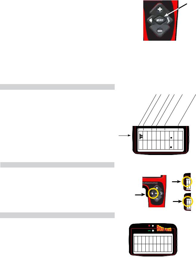
II - FIVE BUTTON OPERATIONAL TERMS
The Five Button Switch performs many different functions |
U |
|
depending on the state of which the PPH is in at the time. To |
||
SEL |
||
standardize our terminology when referring to the individual |
||
buttons of the Five Button Switch, we will use the following |
|
|
identifiers: U, D, L, R, and SEL. |
|
|
See the terms and definitions below: |
|
|
L |
R |
|
U = (+) = UP BUTTON or TOP BUTTON |
|
|
D = (–) = DOWN BUTTON or BOTTOM BUTTON |
|
|
L = (Speaker symbol) or LEFT BUTTON |
|
|
R = (Hot Shot symbol) or RIGHT BUTTON |
|
|
SEL = SELECT BUTTON or CENTER BUTTON |
D |
III - PREFERENCES AND SETTINGS
a) Preference Line (Top Row)
In Power Probe Hook Mode (PPHM) with the probe tip floating or unloaded, the top line of the display shows the present operating parameters of the PPH. You will want to become very familiar with the preference line of the PPH so you will know exactly how it will operate at any given time.
|
On/Off Breaker Amps |
|
Settings |
Volts |
Voltage Setting |
|
|
|
|
||||
|
|
in |
SwitchThreshold |
|
||
Speaker |
Setting |
Power |
AC |
Setting |
|
Drop |
|
Circuit |
|
|
DC |
|
|
|
|
|
|
|
|
|
Preference Line |
2 0 M5 0 |
5 |
|
BA T T 1 2 |
0 |
b) Speaker ON/OFF
To toggle the speaker ON or OFF in PPHM:
1.Press L (Speaker symbol)
2.Notice the speaker symbol in far left of the preference line when the speaker is visible in the Display. This means the
Polarity Tone is ON.
On
 2 0
2 0
BA
Press to toggle
On or Off
Off
2 0
BA
c) Circuit Breaker Preferences
To adjust and set the Circuit Breaker Preferences while in PPHM:
1.Press SEL once. Display shows CIR BREAKR.
2.Press L or R to the desired trip point: 2A, 5A, 10A, 15A, 20A, 25A, 30A, 40A, 50A, or 65A.
3.Press SEL to return to PPHM.
4.Notice the new Circuit Breaker Setting in the preference line.
C I R BR EA K R  6 5 A
6 5 A 

Page 6
III Continued
d) Power Switch Preferences
To adjust and set the Power Switch Preferences while in PPHM:
1.Press SEL once.
2.Press D once. Display shows POW SWITCH.
3.Press L or R to select the desired Power Switch preference:
LATCH, PULSE or MOMENT.
4.Press SEL to return to PPHM.
5.Notice the new Power Switch Setting in the preference line.
Power Switch Behaviors when in PPHM:
M= Moment: When the Power Switch Setting is set to M, battery source power or ground is supplied to the probe tip when you press and hold U(+) or D(–).
L= Latch: When the Power Switch Settings are set to L you can hold continuous battery positive or ground to the probe tip, by pressing the U(+) or D(–). To release power, press U(+) or D(–) again.
P= Pulse: When the Power Switch Setting is set to P, the PPH will cycle battery positive or ground to the probe tip by pressing U(+) or D(–).
It cycles ON for .5 seconds, then OFF for .5 seconds repeatedly. To stop the power cycling, press U(+) or D(–) again.
e) AC Threshold Preferences
To adjust and set the AC Threshold Preferences while in PPHM:
1.Press SEL, once.
2.Press D, twice. Display shows AC THRES.
3.Press L, or R, to select the desired AC Threshold preference: .1, .2, .5, 1, 2, 5, 10, 20, or 50.
4.Press SEL to return to PPHM.
5.Notice the new AC Threshold Setting in the preference line.
f) LED Voltage Drop Preferences
To adjust and set the LED Voltage Drop Preferences while in PPHM:
1.Press SEL once.
2.Press D, 3 times. Display shows LED V DROP.
3.Press R or L, to select the desired Voltage Drop preference:
.2, .5, 1, 2, or 3.
4.Press SEL to return to PPHM.
5.Notice the new LED Voltage Drop Setting in the preference line.
POW SW I T CH  MOME NT
POW SW I TCH
L A T CH
POW SW I T CH
PU L S E
On_ |
Off |
Press Release
ON OFF
On_ |
Off |
Press & |
Press & |
Release |
Release |
ON |
OFF |
On_ |
.5 sec |
.5 sec |
Off |
.5 sec |
|
|
||
Press & |
Press & |
Release |
Release |
START |
STOP |
AC THRE S
5 0
LED V DROP
 5
5
 Loading...