


Power Probe Basic
Instruction
Manual
English
Manual de Instrucciones
Español
The Ultimate in Circuit Testing
www.powerprobe.com

Power Probe Basic |
2 |
|
|
ENGLISH
TABLE OF CONTENTS |
|
INTRODUCTION ........................................................................... |
3 |
WARNING.................................................................................... |
3 |
SAFETY......................................................................................... |
4 |
FEATURES ..................................................................................... |
5 |
HOOK-UP..................................................................................... |
6 |
QUICK SELF-TEST .......................................................................... |
6 |
POLARITY TESTING...................................................................... |
7 |
CONTINUITY TESTING.................................................................. |
8 |
ACTIVATING REMOVED COMPONENTS.................................... |
9 |
TESTING TRAILER LIGHTS AND CONNECTIONS ....................... |
10 |
POWER TESTING A GROUND .................................................. |
11 |
ACTIVATING ELECTRICAL COMPONENTS WITH |
|
POSITIVE (+) VOLTAGE .......................................................... |
12 |
GROUND SWITCHING A CIRCUIT HAVING AN |
|
ELECTRICAL LOAD ................................................................. |
13 |
REPLACING OLD ROCKER SWITCH......................................... |
14 |
ATTACHING THE SWITCH LATCH.............................................. |
14 |
FOLLOWING AND LOCATING SHORT CIRCUITS .................... |
15 |
POWER PROBE WARRANTY...................................................... |
15 |
www.powerprobe.com • 800-655-3585

Power Probe Basic |
3 |
|
|
INTRODUCTION
Thank you for purchasing the Power Probe Basic. It’s your best value for testing automotive electrical problems.
After connecting it to the vehicle’s battery you can now see if a circuit is Positive, Negative or Open by probing it and observing the RED or GREEN LED. You can quickly activate electric components with the press of the power switch and YES, its short circuit protected. Continuity of switches, relays, diodes, fuses and wires are easily tested by connecting them between the auxiliary ground lead and the probe tip and observing the GREEN LED. Check fuses and test for short circuits. Find faulty ground connections instantly. The 20 ft. long lead will reach from bumper to bumper and it has the option to connect a 20 foot extension lead to make it reach up to 40 feet. Great for trucks, trailers and motorhomes. If you are not using a Power Probe in your electrical testing, you are wasting time.
Before using the Power Probe Basic, please read the instruction book carefully.
WARNING!
When the Power Switch is depressed battery current is conducted directly to the tip which may cause sparks when contacting ground or certain circuits. Therefore the Power Probe should NOT be used around flammables such as gasoline or its vapors. The spark of an energized
Power Probe could ignite these vapors. Use the same caution as you would when using an arc welder.
The Power Probe Basic is NOT designed to be used with 110/220 AC-volt house current, it is only for use with 6-12 VDC systems.
www.powerprobe.com • 800-655-3585

Power Probe Basic |
4 |
|
|
SAFETY
Caution - Please Read
To avoid possible electric shock or personal injury and to avoid damage to this unit, please use the Power Probe Basic according to the following safety procedures. Power Probe recommends reading this manual before using the Power Probe Basic.
The Power Probe BASIC is strictly designed for automotive electrical systems. It is to be used on 6 to 12 volt DC only. The power switch should not be pressed when connected to electronic control modules, sensors or any sensitive electronic components. DO NOT connect the Power Probe to AC house electrical such as 115 Volts.
Do not connect to electrical system with higher than rated voltage specified in this manual.
Do not test voltage exceeding the rated voltage on the Power Probe Basic.
Check the PP Basic for cracks or damage. Damage to the case can leak high voltage causing a potential electrocution risk.
Check the PP Basic for any insulation damage or bare wires. If damaged, do not use the tool, please contact Power Probe Technical support.
Use only shrouded leads and accessories authorized by Power Probe to minimize exposed conductive electrical connections to eliminate shock hazard.
Do not attempt to open the PP Basic, no serviceable parts are inside. Opening this unit voids the warranty. All repairs should only be performed by authorized Power Probe service centers.
When maintaining the Power Probe, use only replacement parts certified by the manufacturer.
 Use only in well ventilated areas. Do not operate around flammable materials, vapor or dust.
Be careful when energizing components that have moving parts, assemblies containing motors or high powered solenoids.
Power Probe, Inc. shall not be liable for damage to vehicles or components cause by misuse, tampering or accident.
Power Probe, Inc. shall not be liable for any harm caused by accidents, intentional misuse of our products or tools.
If you have any questions, please go to our website at: www.powerprobe.com or contact our Technical Support at:
800-655-3585.
www.powerprobe.com • 800-655-3585
Power Probe Basic |
5 |
|
|
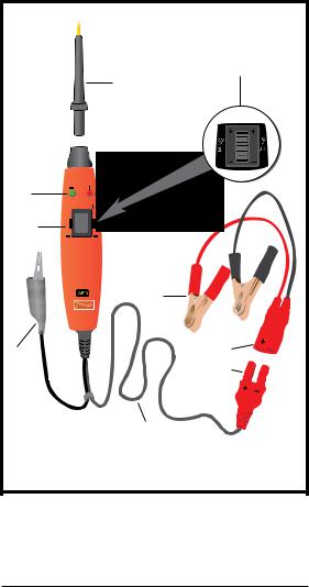
FEATURES |
|
|
|
|
Switch Latch |
Probe Tip |
|
(Included) |
|
|
|
LED |
|
|
Green |
|
|
Rocker |
|
|
Switch |
|
|
Battery |
|
|
Clips |
|
|
6 -12 VOLTS |
|
|
Auxilliary |
|
|
Ground |
|
|
Lead |
|
|
Power Lead |
|
|
www.powerprobe.com |
• |
800-655-3585 |

Power Probe Basic |
6 |
|
|
HOOK-UP
Unroll the Power Cable.
Attach the RED battery hook-up clip to the POSITIVE terminal of the vehicle’s battery.
Attach the BLACK battery hook-up clip to the NEGATIVE terminal of the vehicle’s battery.
BATTERY
QUICK SELF-TEST
Rock the power switch forward (+), the LED indicator should light RED.
Rock the power switch rearward (-), the LED indicator should light GREEN.
 The Power Probe is now ready to use.
Red |
Forward |
|
Position |
||
LED |
||
|
||
Green |
Rearward |
|
Position |
||
LED |
||
|
www.powerprobe.com • 800-655-3585

Power Probe Basic |
7 |
|
|
POLARITY TESTING
By contacting the Power Probe tip to a POSITIVE (+), circuit will light the LED indicator RED.
By contacting the Power Probe tip to a NEGATIVE (-), circuit will light the LED indicator GREEN.
By contacting the Power Probe tip to an OPEN, circuit will be indicated by the LED indicator not lighting.
Red LED = Positive |
|
|
BATTERY |
|
|
|
|
S |
|
|
VOLT |
|
|
12-6 |
BATTERY |
|
Green LED = Negative |
www.powerprobe.com |
• |
800-655-3585 |

Power Probe Basic |
8 |
|
|
CONTINUITY TESTING
By using the Probe Tip together with the auxiliary ground lead, continuity can be tested on wires and components that are disconnected from the vehicle’s electrical system.
 When continuity is present, the LED indicator will light GREEN.
Continuity Testing Application
No LED = No Continuity |
Green LED = Continuity |
6 - |
|
|
|
|
|
|
|
6 -12 VOLTS |
|
|
|
|
|
|
|
|
|
|
|
|
|
|
|
|
|
|
BATTERY BATTERY
www.powerprobe.com • 800-655-3585

Power Probe Basic |
9 |
ACTIVATING REMOVED COMPONENTS
By using the Power Probe tip together with the auxiliary ground lead, components can be activated, thereby testing their function. Connect the negative auxiliary clip to the negative terminal of the component being tested.
Contact the probe to the positive terminal of the component, the LED indicator should light GREEN indicating continuity through the component.
While keeping an eye on the green LED indicator, quickly depress and release the power switch forward (+). If the green indicator changed instantly from GREEN to RED you may proceed with further activation. If the green indicator went off at that instant or if the circuit breaker tripped, the Power Probe has been overloaded. This could happen for the following reasons:
•The contact is a direct ground or negative voltage.
•The component is short-circuited.
•The component is a high amperage component (i.e., starter motor). If the circuit breaker is tripped, it’ll automatically reset to default position.
|
|
Connect the |
|
|
negative auxiliary |
Contact the tip |
|
clip to bulb casing |
|
|
|
to the positive |
|
|
terminal of the bulb |
|
|
Press the power switch |
|
|
forward to activate |
|
|
the bulb |
|
|
Other than light bulbs, you can also activate |
||
other components like fuel pumps, window |
||
motors, starter solenoids, cooling fans, |
BATTERY |
|
blowers, motors, etc. |
|
|
www.powerprobe.com |
• |
800-655-3585 |
 Loading...