


Probe 3
English - Español - Français - Deutsch - Italiano

INTRODUCTION
Thank you for purchasing the NEW Power Probe III (PP3). The PP3 is our most revolution-
ary circuit tester to date. The PP3 literally speeds you through the diagnosing of 12 to 24 volt
automotive electrical systems. After connecting the PP3’s clips to the vehicle’s battery, the auto-
motive technician can determine at a glance, the voltage level and the polarity of a circuit with
out running for a voltmeter or reconnecting hook-up clips from one battery pole to the other. The
power switch allows the automotive technician to conduct a positive or negative battery current
to the tip for activating and testing the function of electrical components without wasting time
with jumper leads. And yes, the PP3 is short circuit protected. It tests for bad ground contacts
instantly without performing voltage drop tests. It allows you to follow and locate short circuits
without wasting precious fuses. The Power Probe can also test for continuity with the assistance
of its auxiliary ground lead. With a fl ip of the power switch, you will know at a glance that your
PP3 is functioning without running to the battery as you would otherwise have to do with simple
test lights. The PP3’s 20ft (extendable) cable allows you to test along the entire length of the
vehicle without constantly searching for ground hook-ups. An absolute must for every automo-
tive technician looking for a fast and accurate solution to electrical systems diagnostics.
Before using the Power Probe III please read the instruction booklet carefully.
Warning!
When the PP3 switch is depressed battery current/voltage is conducted directly to the tip
which may cause sparks when contacting ground or certain circuits. Therefore the Power Probe should
NOT be used around fl ammables such as gasoline or its vapors. The spark of an energized Power Probe
could ignite these vapors. Use the same caution as you would when using an arc welder.
The Power Probe III and the ECT 2000 are NOT to be used with 110/220-volt
HOME electrical, it is only for use with 12-24-volt systems.
1

Table of Contents
Hook-up and quick self-test ............................................................................................................. 3
Turning the Audio Tone On & Off ................................................................................................... 3
Circuit Breaker .................................................................................................................................4
Voltage & Polarity testing ................................................................................................................ 5
Continuity testing .............................................................................................................................5
Activating components out of vehicle’s electrical system ............................................................... 6
Testing trailer lights and connections............................................................................................... 7
Activating electrical components in the Vehicle .............................................................................. 8
Activating electrical components with Ground ............................................................................... 9
Checking for bad ground contacts ................................................................................................. 10
Following & Locating Short Circuits ............................................................................................10
Red/Green Indicator & Audio Tone ...............................................................................................10
Modes 1, 2, 3 .................................................................................................................................. 11
Modes 4, 5, Chart ........................................................................................................................... 12
Specifi cations ................................................................................................................................. 13
Rocker Switch Replacement .......................................................................................................... 14
Power Probe warranty ..................................................................................................... Back Cover
IMPORTANT TIP:
When powering-up components, you can increase the life of your Power Probe switch if you fi rst press
the switch, then contact the tip to the component. The arcing will take place at the tip instead of the contacts of the switch.
2
English
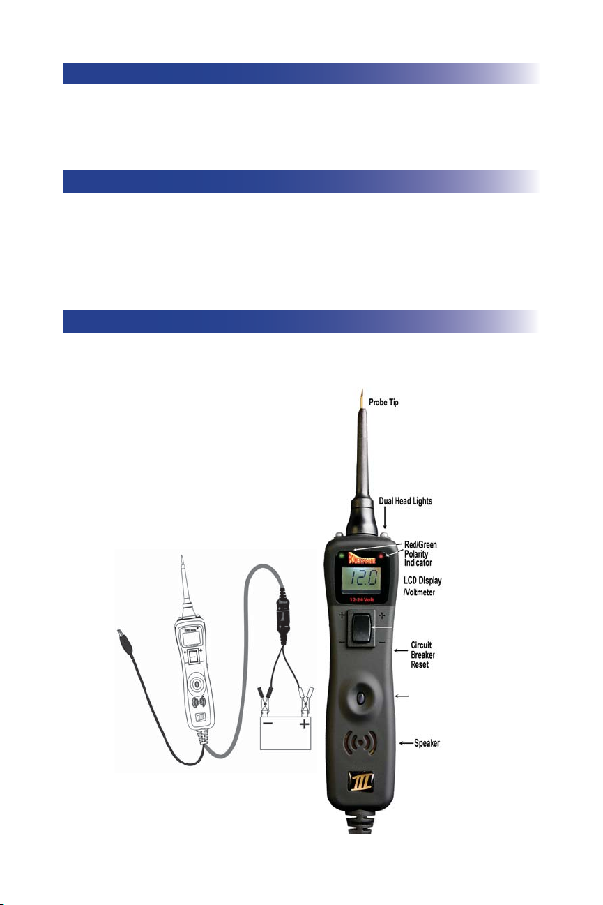
HOOK-UP
/
3
Mode
Button
Power Switch
Unroll the Power Probe cable. Connect the RED battery hook-up clip to the POSITIVE terminal of the
vehicle’s battery. Connect the BLACK battery hook-up clip to the
NEGATIVE terminal of the vehicle’s
battery. When the PP3 is fi rst connected to a battery (power source), it will sound a quick high and then
low beep and go into “Power Probe Mode (PPM) (See Mode #1 on page 10) and the 2 bright white LEDs
(dual head lights) will be on to illuminate the test area of the probe tip.
While the PP3 is in Power Probe Mode, press the power switch forward to activate the tip with a positive
(+) voltage. The positive sign (+) LED should light red and the LCD display will read the battery (supply)
voltage. If the tone feature is turned on, a high pitched tone will sound. Press the power switch rearward
to activate the tip with a
negative (-) voltage. The negative sign (-) LED should light green and the LCD
display will read “0.0” (ground). If the tone feature is turned on, a low pitched tone will sound. The Power
Probe is now ready to use. If the indicator did not light, depress the reset button of the circuit breaker on
the right side of the housing and try the self test again.
QUICK SELF-TEST (PPM)
TURNING THE AUDIO TONE ON/OFF (PPM)
While the PP3 is in Power Probe Mode, just do a quick press of the mode button to toggle the tone on or off.
While quickly pressing (a quick press and release) the mode button, if a short high beep is heard, this means
the audio tone is turned on. If a short low beep is heard, the audio tone is turned off.
4
12.0
0
.0
While the PP3 is in Power Probe Mode. Contact the probe
tip to a
NEGATIVE circuit. The green negative sign “-
” LED will light. If the audio feature is turned on, a low
pitched tone will sound.
VOLTAGE & POLARITY TESTING (PPM)
While the PP3 is in Power Probe Mode, contact the probe tip to a POSITIVE circuit. The red positive sign “+”
LED will light and the voltmeter displays the voltage with a resolution of 1/10th of a volt (0.1v).
If the audio feature is turned on, a high pitched tone will sound. (See RED/GREEN POLARITY INDICATOR
& AUDIO TONE on page 10)
While the PP3 is in Power Probe Mode, contact the probe tip to a NEGATIVE circuit. The green negative
sign “–” LED will light and the voltmeter displays the voltage. If the audio feature is turned on, a low pitched
tone will sound.
Contacting the Power Probe tip to an OPEN circuit will be indicated by neither of the LED indicators lighting.
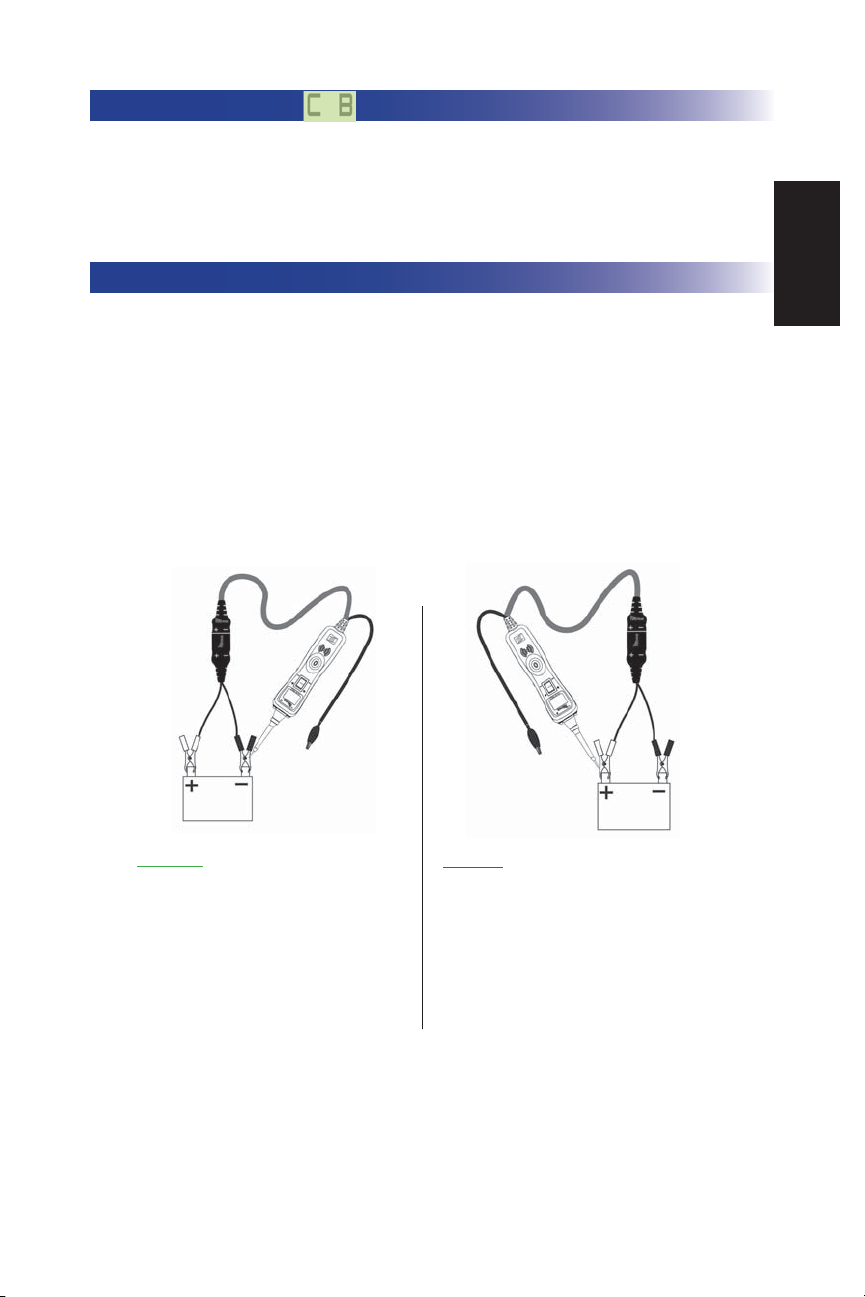
In Power Probe Mode (Mode #1) with a the circuit breaker tripped, the LCD will display the symbol “C B”.
(see page 11-12 for detail) All other functions of the PP3 are still active. This means that you can still probe a
circuit and observe the voltage reading. When the circuit breaker is tripped, the PP3 will NOT be able to con-
duct battery current to the tip even when the power switch is pressed. Intentionally tripping the breaker and us-
ing the PP3 to probe can be considered an added precaution against accidental pressing of the power switch.
CIRCUIT BREAKER
While the PP3 is in Power Probe Mode, contact the probe tip to
a
POSITIVE circuit. The red positive sign “+” LED will light
and the voltage reading of the circuit will be indicated on the
LCD display. If the audio feature is turned on, a high pitched
tone will sound.
English
 Loading...