


Probe 1
English - Español - Français - Deutsch - Italiano

INTRODUCTION
Thank you for purchasing Power Probe products. The Power Probe is the best professional elec-
trical tester for reducing diagnostic time in 6 to 24 volt automotive electrical systems. After a
simple hook-up of the Power Probe to the vehicle’s battery, the automotive technician can deter-
mine at a glance at the red/green LED indicator, if a circuit is positive, negative or open without
reconnecting hook-up clips from one battery pole to the other. The Power Probe switch allows
the automotive technician to conduct a positive or negative battery current to the tip for testing
the function of electrical components without the use of jumper wires. And yes, it is short-circuit
protected. It tests for bad ground contacts instantly without performing voltage drop tests. It al-
lows you to follow and locate short circuits without wasting precious fuses. The Power Probe
can also test for continuity with the assistance of its auxiliary ground lead. With a fl ip of the
power switch, you will know at a glance that your Power Probe is functioning without running
to the battery as you would otherwise have to do with simple test lights. The Power Probe’s long
cable allows you to test along the entire length of the vehicle without constantly searching for
ground hook-ups. If you are not using the Power Probe now in your electrical testing, you are
spending too much diagnosic time.
Before using the Power Probe please read the instruction book carefully.
Warning!
When the Power Probe’s switch is depressed battery current is conducted directly to the tip
which may cause sparks when contacting ground or certain circuits. Therefore the Power
Probe should NOT be used around fl ammables such as gasoline or its vapors. The spark of
an energized Power Probe could ignite these vapors. Use the same caution as you would when
using an arc welder.
The Power Probe I & II and the ECT 2000 are NOT to be used with 110/220-volt house cur-
rent, it is only for use with 6-24-volt systems.
1

Table of Contents
Power Probe I & II
Hook-up and quick self-test .....................................................................................................3
Polarity testing .........................................................................................................................4
Continuity testing .....................................................................................................................5
Activating components out of vehicle’s electrical system .......................................................6
Testing trailer lights and connections.......................................................................................7
Activating electrical components with positive (+) voltage ....................................................8
Activating electrical components with negative (-) voltage ....................................................9
Jumper lead feature ................................................................................................................10
Checking for bad ground contacts .........................................................................................11
Following and locating short circuits .....................................................................................11
Using the light and tone (Power Probe II) .............................................................................12
IMPORTANT TIP: When powering-up components, you can increase the life of your Power Probe switch
if you fi rst press the switch, then contact the tip to the component. The arcing will take place at the tip
instead of the contacts of the switch.
2
English
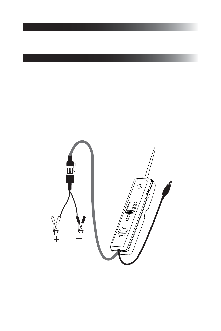
HOOK-UP
QUICK SELF-TEST
Unroll the Power Probe cable.
Clamp the RED battery hook-up clip to the POSITIVE terminal of the vehicle’s battery.
Clamp the BLACK battery hook-up clip to the NEGATIVE terminal of the vehicle’s battery.
Rock the power switch forward (+), the LED indicator should light RED.
(The PP2 will sound a high pitched tone in addition to the red light)
Rock the power switch rearward (-), the LED indicator should light GREEN.
(The PP2 will sound a low pitched tone in addition to the green light)
The Power Probe is now ready to use.
If the indicator did not light, depress the reset button of the circuit breaker on the right side of
the housing and try the self test again.
CONEXIÓN
/
/
3

POLARITY TESTING
Contacting the Power Probe tip to a POSITIVE (+) circuit will light the LED indicator RED.
(The Power Probe 2 audio feature will sound a high pitched tone when contacting positive)
Contacting the Power Probe tip to a NEGATIVE (-) circuit will light the LED indicator
GREEN.
(The Power Probe 2 audio feature will sound a low pitched tone when contacting negative)
Contacting the Power Probe tip to an OPEN circuit will be indicated by the LED indicator not
lighting.
Red = positive
Green = negative
4
English
 Loading...