


Diagnose Electrical
Circuits Like a Pro!
English - Español - Français - Deutsch - Italiano

Contents |
|
Congratulations....................................................................................................... |
4 |
Parts......................................................................................................................... |
5 |
The SMART transmitter ...................................................................................... |
6 |
Charcteristics of the Short/Grounded Circuit signal............................................... |
8 |
Charcteristics of the Open Circuit signal ......................................................... |
9&10 |
The SMART receiver.......................................................................................... |
11 |
Battery Installation................................................................................................ |
12 |
Testing the Smart Receiver ................................................................................... |
12 |
Pulse Mode............................................................................................................ |
12 |
Locking the Sensitivity of Short//Grounded Circuit signal .................................. |
14 |
Locking the Sensitivity of Open Circuits.............................................................. |
14 |
Direction to Short.................................................................................................. |
15 |
How to Use the ECT-2000 in Diagnosing Circuits ............................................... |
16 |
2

|
Contents |
How to Trace Out a Short Circuit to Chassis Ground |
........................................... 17 |
Isolate your Circuit ............................................................................................... |
18 |
Verify the Short Circuit to Ground........................................................................ |
18 |
Short Circuit inside a Wire Harness...................................................................... |
19 |
Reception Distance and What that Means ............................................................ |
20 |
Tracing Circuits that are Shielded................................................................................ |
21 |
Open Circuit Signal vs /Grounded Circuit Signal...................................................... |
22 |
How to Trace an Open Circuit ..................................................................................... |
23 |
Verify an Open Circuit................................................................................................. |
23 |
Bench Tracing a Wire Harness..................................................................................... |
24 |
Tracing out Battery Drain or Current Draw................................................................. |
25 |
Circuit Wiggle & Flex Test .......................................................................................... |
26 |
Index ............................................................................................................................ |
27 |
English
3
Congratulations
Thank you for choosing the Power Probe “SMART ECT-2000” (Electronic Circuit Tracer2000)
This instruction booklet will give you some valuable diagnosing tips gathered from the field and from our testing lab. This instruction booklet has convenient references that will take you to appropriate pages that provide more information and clarification. Taking the time to read this instruction booklet carefully will give you valuable insight to these detailed techniques in tracing automotive circuits.
We designed the ECT-2000 as a quick solution to your automotive circuit problems. The ECT 2000 consists of 2 main components. A SMART transmitter and a SMART receiver along with a set of connection adapters that will help you:
•Locate short circuits without unnecessarily removing plastic panels, molding, and carpet.
•Trace wires to see where they lead
•Locate electrical components in the vehicle
•Find open circuits, switches or breaks in wires
•Trace and locate the cause of a severe battery drain
•Test and find intermittent connections
•Check continuity with the assistance of the Power Probe III
These features are extremely handy for the professional technician that understands automotive electrical. An appropriate schematic or wiring diagram is always useful and many times necessary when tracing circuits. The better you understand your circuit, the better the ECT-2000 can assist you.
4
#PPPP02 - Piercing Probe
#20014 - Universal Wire Adapter*
#AA1 #AA2
#AA4 #AA3 #AA6 Blade
Back Probe Probe
Light Bulb Adapters
#PNECT000R
SMART receiver
#PNECT057
Alligator Clip Adapter
#PN012SET
Battery Hook-up Clip Set
#PNECT000T
SMART transmitter
Parts English
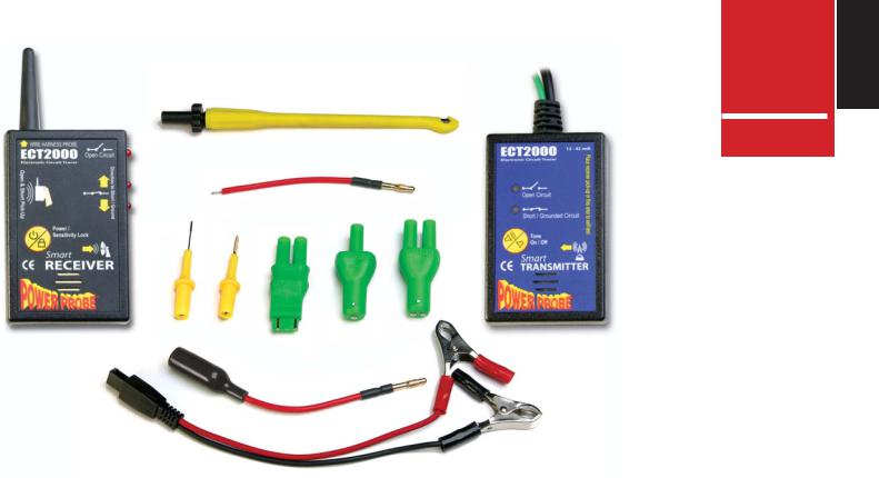
Included in the Kit:
SMART transmitter SMART receiver 1-Blade Probe** 1-Back Probe**
3-Light Bulb Adapters**
1-Piercing Probe
1-Alligator Clip Adapter
1- Battery Hook-up Clip Set
1-Universal Wire Adapter*: (You can solder to any connection for custom use.)
*Extra universal wire adapters can be purchased. (Sold in packs of 5, Part #PNECT050)
All banana jacks/plugs are standard 4mm making other test leads or Adapters usable with this product.
**See pg. 16 for application
5

The SMART transmitter
The SMART transmitter is designed to generate Grounded Circuit signals and Open Circuit signals. The grounded and the open circuit signals are very different from each other, so it is very important to understand the differences in each signal type. (see “Characteristics of the Short/Grounded Circuit Signal” pg.. 8 and Characteristics of the Open Circuit Signal” pg..9)
Power Lead
The 20 ft. power lead of the SMART transmitter supplies power by connecting directly to the vehicles battery and the long length provides easy access to circuits throughout the vehicle. The RED clip connects to the positive side of the battery and the BLACK clip connects to the negative. It can be connected to a power source from 12 to 42 volts.
Signal Lead
The signal lead with green banana jack, plugs into the assortment of adapters, probes, and clips that are provided for you in the ECT-2000 kit. These accessories simplify connecting to your circuit.
Tone On/Off - Toggle Tone
“Tone On/Off” button toggles the tone of the SMART transmitter’s speaker on or off.
The toggle tone feature of the SMART transmitter gives you the ability to detect changes in the circuit to detect intermittent problems. (See “Circuit Wiggle and Flex Test” pg.. 26)
Self-Test
The area located on the face of the SMART transmitter, with the words “Place receiver pick-up in this area to self-test” is used for testing the SMART receiver.
6
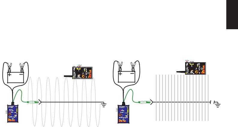
After connecting the SMART transmitter’s 20 ft. power lead to the vehicle’s battery, a signal is generated through the green signal wire and banana plug. This is connected to the circuit you want to trace. The signal will radiate along the circuit, which you can detect by using the SMART receiver. There are two types of circuit signals that the SMART transmitter generates. They are the Grounded Circuit SIGNAL and the OPEN CIRCUIT SIGNAL.
It is very important to familiarize yourself with both of these signals and how they work in your circuit. The “Grounded Circuit signal” and the “open circuit signal” are different from each other, which you should understand. (See: “Characteristics of the Short/Grounded Circuit Signal” pg.. 8 and “Characteristics of the Open Circuit Signal” pg. 9&10)
The 2 main features of the ECT2000 is that it transmits a signal into a circuit with the SMART transmitter and then you trace it with the SMART receiver . The easiest way to insure that you are following the problem circuit is to isolate it from other parallel circuits.
English
Complete Circuit Signal |
Open Circuit Signal |
7
Characteristics of the Short/Grounded Circuit Signal:
1.Strongest when flowing exclusively through one wire
When the signal is conducting through only one wire, the signal strength is at its maximum because 100% of the signal is traveling through that wire exclusively to return back to the negative side of the battery. If the signal branches out to parallel circuits, its strength divides and of course is weaker in each branch of the divided circuit. But when the signal recollects through the single negative cable to return to the battery, the signal strength is at its maximum again because 100% of the signal is concentrated
through the single negative battery cable. (see “Isolate the Circuit You are Tracing” pg. 18)
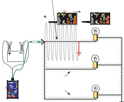
2.Travels the path of least resistance
In case of a short circuit that blows its fuse reliably, you can sometimes get away with not having to isolate the circuit. The majority of the signal will follow the path of least resistance through the short and then back to the battery. In fig.1, you can see the majority of the signal travels right to the short circuit. You can also see only a small portion of the signal running through parallel wires.
3. A 4 KHz Polarized Signal
Path of least resistance
Major portion of signal goes into short (ground) 
Lights have resistance and limit signal flow
Very small traces of signal branch into parallel circuits
Fig. 1
The fact that the Grounded Circuit signal is a 4 KHz polarized signal provides directional information for the SMART receiver to pick up. This  capability to indicate the direction to the short or ground takes the guesswork out of tracing grounded circuits. (See “Direction to the Short” pg. 15)
4. Carries a current of only 100 mA.
When generating a short/Grounded Circuit signal, a maximum of 100 milliamp flows from the signal lead. This keeps you safe from damaging sensitive computer circuits.
8

Characteristics of the Open Circuit Signal are:
1.Transmits through NON Conductive Materials
The signal that the ECT transmits when tracing open circuits, radiates what is called an E-field. For the sake of simplicity we will refer to an E-field in this manual as an “Open Circuit Signal”.
The open circuit signal radiates from wires and passes through non conductive material such as dry carpet, plastic panels or plastic molding. The SMART receiver is used to detect these signals so you can trace and locate the open or break in the circuit.
(See “Locking the Sensitivity” pg. 14)
2.Easily Shielded by Conductive Materials
The open circuit signal is however easily shielded by conductive materials such as metal, wet carpet, neighboring wires in a harness and even your hand. This means that if conductive materials are between the transmitting wire and the SMART receiver, the open circuit signal will not penetrate through and therefore not be detected by the receiver. So it is necessary to be aware of possible shielding issues and try to avoid them as much as possible.
A great alternative to the SMART receiver in detecting open circuit signals is to use the Power Probe III by direct contact. (see “Verify an Open Circuit” pg. 23)
(continued on next page)
|
Open signal passes |
English |
|
||
|
|
|
|
through dry non- |
|
|
conductive material |
|
|
|
|
|
|
|
Dry Carpet / Plastic Panels & Molding
Holding the receiver by this corner, prevents your hand from sheilding the open circuit signal.
Wet Carpet / Metal/ Shielding Wire Harness
9
 Loading...