

Page 1

Page 2

The Power Probe Hook Operations Manual
Thank you for purchasing the Power Probe Hook (PPH).
You now have in your possession the most advanced and reliable Power Probe Circuit Tester in its class.
Technicians who have experienced the Power Probe advantages will nd the Hook to be even better. It is a
no nonsense electrical circuit tester that is designed to diagnose circuits fast without wasting time fumbling
with multiple testers, jumper wires and meters. The PPH provides controlled POWER to your circuit for dy-
namically testing the full function of electrical components bad grounds and circuit connectivity.
The benets that come from having the ability to supply POWER to circuits and simultaneously observe
AMPS, VOLTS, and RESISTANCE are huge!
The PPH also performs passive measurements for diagnosing sensitive automotive circuits, but CAUTION
must be stressed before you press the power switch to activate circuits. Just as a scalpel is designed for a
professional surgeon, the PPH is designed for professional technicians.
Enjoy your new found power with the PPH. If you have any questions please go to our
website www.powerprobe.com or give us a call: 800-655-3585.
“The Ultimate Circuit Tester”
In 1991 Power Probe emerged from one simple
idea: “Make the Ultimate Circuit Tester”
From the very rst Power Probe Circuit Tester,
it was evident that we had invented something
unique. It didn’t take long for the Power Probe to
become an industry standard for diagnosing and
probing DC electrical circuit.
Year after year we have made improvements to
our tools. We listen to our customers and with
Power Probe’s desire to serve the technician, it
has guided us to provide information, service and
product tools that are a MUST for every mechanic.
890 Mariner Street
Brea, California 92821
toll free 800.655.3585
local 714.990.9443
fax 714.990.9478
The Serial Number can also be found on the back of the unit or box.
Page 3
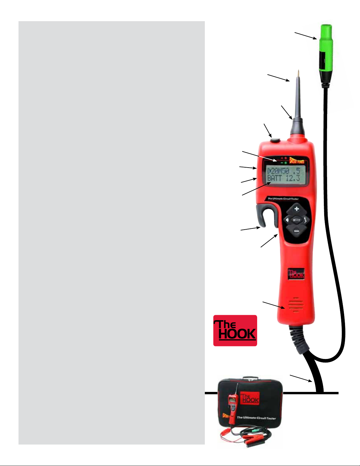
Table of Contents
START-UP ................................................................................................................................4-I
Operating Voltage Source .......................................................................................................4-I a
Connecting to the Vehicle’s Battery (Voltage Source) ............................................................4-I b
Y-Connector with Battery Clips ................................................................................................4-I c
Auxiliary Ground Lead ............................................................................................................4-I d
Flashlight .................................................................................................................................4-I e
Sleep Mode ..............................................................................................................................4-I f
FIVE BUTTON OPERATIONAL TERMS .....................................................................................5-II
Auxiliary Ground
Lead with a 4mm
gold plated jack.
Removable
Probe Tip
4mm
banana jack
PREFERENCES AND SETTINGS................................................................................................5-III
Preference Line .......................................................................................................................5-III a
Speaker ON/OFF .....................................................................................................................5-III b
Circuit Breaker Preferences .....................................................................................................5-III c
Power Switch Preferences .......................................................................................................6-III d
AC Threshold Preferences ........................................................................................................6-III e
LED Voltage Drop Preferences ................................................................................................6-III f
POWER PROBE HOOK MODE (PPHM) ....................................................................................7-IV
Voltage Testing in PPHM: .......................................................................................................7-IV a
Resistance Testing in PPHM: ...................................................................................................7-IV b
Activating Electrical Components, Current Draw Testing and Calculated Resistance in PPHM: .......8-IV c
AC Peak to Peak/ Frequency Measuring in PPHM: ...............................................................8-IV d
Hot Shot Testing in PPHM: ....................................................................................................9-IV e
CONTINUITY and RELAY TESTER ............................................................................................9-V
POWER PLUS MODE ...............................................................................................................10-VI
VOLT METER MODE .................................................................................................................10-VII
OHM METER MODE ................................................................................................................11-VIII
COUNTER MODE ......................................................................................................................12-IX
Duty Cycle/Frequency ..............................................................................................................12-IX a
Positive Pulse Width/Frequency ..............................................................................................12-IX b
Negative Pulse Width/Frequency ............................................................................................12-IX c
Pulse Counter ..........................................................................................................................12-IX d
Continuity Jack
& Rubber Cover
Positive and
Negative
indicator lights
Preferences
settings
Battery
voltage
LCD
backlit
display
“Hook” for
easy placement while
working
5 button
Navigation
Speaker
VOLTAGE REFERENCE SUPPLY MODE ....................................................................................13-X
CONTRAST: ..............................................................................................................................13-XI
SAVE PREFERENCES AND DEFAULT SETTINGS: ....................................................................14-XII
SAFETY: ...................................................................................................................................15
FACTS AND TIPS: ....................................................................................................................16
SPECIFICATIONS: ....................................................................................................................17
WARRANTY POLICY: ...............................................................................................................17
10 Gauge
Power Lead
#PPH1 Kit includes:
Power Probe Hook
3” Probe Tip
Battery hook-up clips
3 Wire Continuity Leads
Instruction manual
Page 4

Page 4
LN
I - START-UP
a) Operating Voltage Source
The PPH is designed for use in 12 to 48 VDC electrical systems and comes supplied with a 20 ft., 10-gauge coax cable
and 2 heavy-duty battery hook-up clips.
b) Connecting to the Vehicle’s Battery
(Voltage Source)
Connect the red clip to the positive terminal of the vehicles
battery source and the black clip to negative or ground. The
PPH start-up tone will sound and the indicator light on the YConnector with Battery Clips will illuminate. This tells you that
the Hook is connected correctly and the internal fuse of the
Y-battery-clip-connector is working properly.
c) Y-Connector with Battery Clips
The Y-Connector with Battery Clips has a safety fuse built into
it. The built-in fuse will blow in the event the 10-gauge coax
power cable gets clamped or pinched in a door or hood causing a short circuit.
Lights up when
connected to a
power source.
Y-Connector
0M5
0
2
1ATTB0
52
Note: If the Y-Connector with Battery Clips does not light when
properly connected to the voltage source, you probably have a
damaged 10 gauge coax power cable. It is recommended that
the cable be inspected and tested before replacing a new YConnector with Battery Clips.
Contact your distributor or Power Probe, Inc. for a replacement.
d) Auxiliary Ground Lead
The auxiliary ground lead provides ground to circuits and
components that are not already connected to ground. It also
serves as the negative lead for resistance testing.
To test the auxiliary ground lead, contact the probe tip and the
auxiliary ground lead together. The Green LED on the display
should light. This shows that the auxiliary ground lead is working properly.
If the green LED does not illuminate, check the replaceable 25
amp fuse in the auxiliary ground lead. The fuse is a protection
in the event the lead is inadvertently contacted with battery
positive.
e) Flashlight
Flashlight is a standard feature on the PPH. The bright LED
Flashlight is always ON making it possible to probe under
dashboards and in dark areas.
Flashlight
12 - 48 VDC
To replace the fuse
remove cover.
Green LED
HOM
H
0
0
1
f) Sleep Mode
The PPH goes to sleep after 10 minutes of inactivity and you
will see SLEEPING in the display. The Flashlight and the LCD
backlight will turn off. To wake it up, just press any button or
contact the probe tip to a circuit.
S E
P
IE G
Page 5
II - FIVE BUTTON OPERATIONAL TERMS
5
0M5
0
1
0
2
5
0M
0
1
0
2
5
Page 5
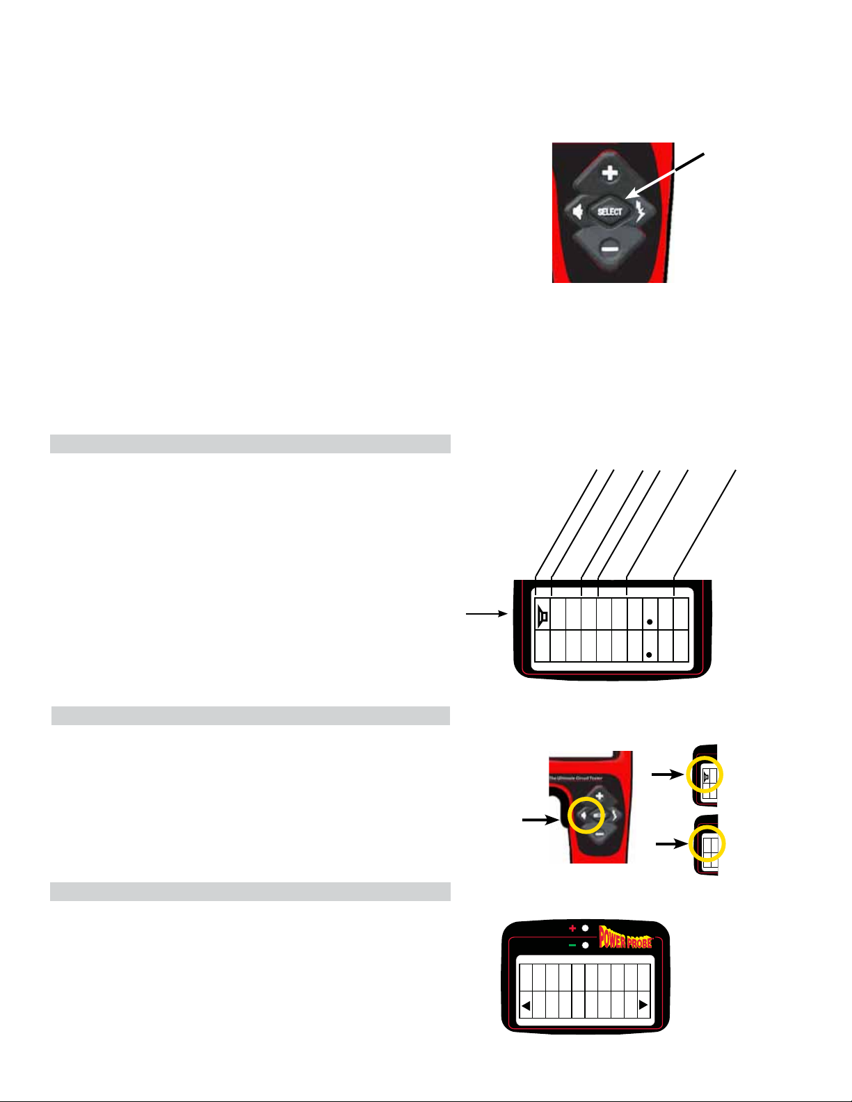
The Five Button Switch performs many different functions
depending on the state of which the PPH is in at the time. To
standardize our terminology when referring to the individual
buttons of the Five Button Switch, we will use the following
identiers: U, D, L, R, and SEL.
See the terms and denitions below:
U = (+) = UP BUTTON or TOP BUTTON
D = (–) = DOWN BUTTON or BOTTOM BUTTON
L = (Speaker symbol) or LEFT BUTTON
R = (Hot Shot symbol) or RIGHT BUTTON
SEL = SELECT BUTTON or CENTER BUTTON
III - PREFERENCES AND SETTINGS
a) Preference Line (Top Row)
In Power Probe Hook Mode (PPHM) with the probe tip oating
or unloaded, the top line of the display shows the present operating parameters of the PPH. You will want to become very
familiar with the preference line of the PPH so you will know
exactly how it will operate at any given time.
Circuit Breaker
Setting in Amps
Speaker On/Off
U
SEL
RL
D
DC Voltage
AC Threshold
Power Switch Settings
Setting in Volts
Drop Setting
Preference Line
b) Speaker ON/OFF
To toggle the speaker ON or OFF in PPHM:
1. Press L (Speaker symbol)
2. Notice the speaker symbol in far left of the preference line
when the speaker is visible in the Display. This means the
Polarity Tone is ON.
c) Circuit Breaker Preferences
To adjust and set the Circuit Breaker Preferences
while in PPHM:
1. Press SEL once. Display shows CIR BREAKR.
2. Press L or R to the desired trip point: 2A, 5A, 10A, 15A,
20A, 25A, 30A, 40A, 50A, or 65A.
3. Press SEL to return to PPHM.
4. Notice the new Circuit Breaker Setting in the
preference line.
B
Press to toggle
On or Off
I
0M5
A
TT
RBR
5A6
E
0
1
KAC
2
52
0
On
2
ATTB
Off
2
ATTB
R
Page 6
Page 6
III Continued
d) Power Switch Preferences
To adjust and set the Power Switch Preferences
while in PPHM:
1. Press SEL once.
2. Press D once. Display shows POW SWITCH.
3. Press L or R to select the desired Power Switch preference:
LATCH, PULSE or MOMENT.
4. Press SEL to return to PPHM.
5. Notice the new Power Switch Setting in the preference line.
WIH
WS
O
M
ME
O
N
T
On_
CTP
Off
Power Switch Behaviors when in PPHM:
M= Moment: When the Power Switch Setting is set to M, bat-
tery source power or ground is supplied to the probe tip when
you press and hold U(+) or D(–).
L= Latch: When the Power Switch Settings are set to L you
can hold continuous battery positive or ground to the probe tip,
by pressing the U(+) or D(–). To release power, press U(+) or
D(–) again.
P= Pulse: When the Power Switch Setting is set to P, the PPH
will cycle battery positive or ground to the probe tip by pressing
U(+) or D(–).
It cycles ON for .5 seconds, then OFF for .5 seconds repeatedly. To stop the power cycling, press U(+) or D(–) again.
e) AC Threshold Preferences
To adjust and set the AC Threshold Preferences
while in PPHM:
1. Press SEL, once.
2. Press D, twice. Display shows AC THRES.
3. Press L, or R, to select the desired AC Threshold
preference: .1, .2, .5, 1, 2, 5, 10, 20, or 50.
4. Press SEL to return to PPHM.
5. Notice the new AC Threshold Setting in the preference line.
P
WSWI H
O
LA
TC
WIH
WS
O
P
LS
U
A
CTH
50
H
E
R
Press
ON
On_
CT
CTP
Off
Press &
Release
ON
On_
Off
Press &
Release
START
.5 sec
Release
OFF
Press &
Release
OFF
.5 sec
.5 sec
Press &
Release
STOP
SE
f) LED Voltage Drop Preferences
To adjust and set the LED Voltage Drop Preferences
while in PPHM:
1. Press SEL once.
2. Press D, 3 times. Display shows LED V DROP.
3. Press R or L, to select the desired Voltage Drop preference:
.2, .5, 1, 2, or 3.
4. Press SEL to return to PPHM.
5. Notice the new LED Voltage Drop Setting in the
preference line.
OR
EV
L
D
D
5
P
Page 7

Page 7
IV - POWER PROBE HOOK MODE (PPHM)
In PPHM the “Smart Tip Advantage” gives you several new powerful tools to help you x electri-
cal problems faster than any other circuit tester in its class. Why?
Because it automatically selects the:
RIGHT METER and the RIGHT FUNCTION for the RIGHT CIRCUIT condition.
a) Voltage Testing in PPHM
Voltage testing is as easy as contacting the probe tip to a
circuit and reading the display. There is no need to select the
voltmeter before probing because the PPH does that for you
automatically. The PPH also provides both the battery source
voltage and the probe tip voltage on the display screen for
easy voltage comparing.
To test for voltage in PPHM:
1. Take note of the preference parameters in the display.
2. Contact the probe tip to a voltage potential.
3. Take note of the difference between VOLT and BATT on
the display.
If the voltage difference is within the LED Voltage Drop Preferences, the Red LED will light and the HOT SHOT symbol will
be present.
If the voltage difference is greater than the LED Voltage Drop
Preferences, the LED will not light.
4. Voltage is measured from 0 to 99.9 volts.
:
Voltage Testing
V
OT
B
A
L
11
T12
T
8
6
11.8V
b) Resistance Testing in PPHM:
Resistance testing is as easy as contacting the probe tip to
a circuit or a component and reading the display. There is no
need to select the Ohm Meter before probing because the
PPH does that for you automatically. It will also auto-range the
decimal point.
To test for resistance in PPHM:
1. Contact the probe tip to a circuit or component with
resistance to ground.
Resistance is measured and displayed from 0 to 15 megohms.
It is necessary to connect the ground lead to a chassis or other
common ground point to accurately measure 2 Ohms or less.
This will eliminate voltage drops within the 20 ft cable and
improve the accuracy.
Resistance Testing
100Ω
HOM
1 0
0
0
Page 8

Page 8
IV Continued
c) Activating Electrical Components,
Current Draw Testing and Calculated
Resistance in PPHM:
Activating Electrical Components in PPHM is one of the main
features that make the PPH very useful. The Power Switch, (+)
and (–), behave differently according to the Switch Preferences.
Notice the Power Switch Settings on the preference line (see
section III-a). Power Switch Behaviors (see section III-d).
Arc Detect is a safety feature that will help protect your circuit,
your tip your accessories and YOU! Arc Detect will shut off power to the probe tip if an arc is detected. If you activate the probe
tip and then connect or disconnect it, causing an arc, you will
hear a short high-pitched tone to let you know it has detected
and extinguished an arc. Sometimes components that produce
excessive arcs can be difcult to activate in PPHM. You may
need to resort to Power Plus Mode (see section VI) for these
kinds of components because the Arc Detect is disabled.
Battery Volts
Load Activated
MAP0
55
OM2
20
1
H
Ground
Current Draw Testing and Calculated Resistance are dynamic tests that are performed by activating circuits or electrical
components with the vehicle’s battery power through the PPH
and measuring the Amps and Ohms. Since the measurements
are made while under power you are getting a true indication as
to its real operating integrity.
To test the current draw and calculated resistance of an
electrical component in PPHM:
1. Contact the probe tip to the positive terminal of an electric
component that is properly grounded.
2. Press and hold (+). The PPH supplies power to activate it.
During activation the PPH displays the AMMETER and OHM
METER simultaneously.
3. Read the Current Draw displayed as AMP on the screen.
4. Read the Calculated Resistance displayed as OHM on the
screen.
5. If the display shows CIR BREAKR TRIP when you attempt
to activate the electrical component, you will need to
increase the trip point by adjusting it in the Circuit Breake
preferences. (See section: III-c)
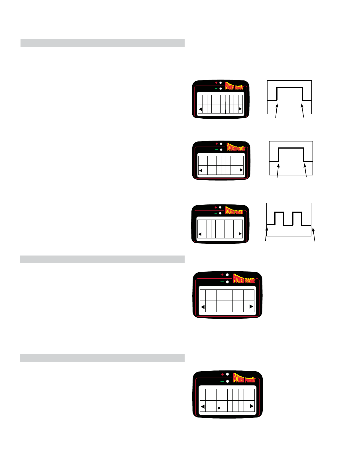
d) AC Peak to Peak/ Frequency
Measuring in PPHM:
When testing circuits that generate signals or waveforms,
such as primary ignition systems, distributor pick-ups, variable
reluctance sensors, fuel metering solenoids, wheel speed,
cam and crank sensors, etc. An oscilloscope is the ideal tool.
If you don’t have an oscilloscope but still need to know if these
components are generating a signal, you can use the AC Peak
to Peak/Frequency feature of the PPH.
Battery Volts
Starter
Motor
13.6V—
0V—
Press & Hold
the (+) Power
button
Press
Power
Switch
Ground
Solenoid
clicks when
Activated
950Hz
To test for a signal that is being generated by and electronic sensor in PPHM:
1. Adjust your AC Threshold Setting to .1 (see section III-e).
2. Probe the output terminal of the sensor and operate it.
3. You should see the Peak – Peak and Frequency in the
display, indicating a signal is being generated.
PP
–
36V
1
50HZ
9
Page 9

IV Continued
e) Hot Shot Testing in PPHM:
Page 9
Hot Shot is used to test for certain corroded or resistive
ground connections. Hot Shot also tests for certain corroded
or resistive positive connections.
Hot Shot is intended for power feeds 5 amps or greater only. It
Good Ground
Corrosion
Hot Shot
works by briey activating a circuit for less than 7 milliseconds
with battery positive or battery ground and determines if the
conductivity passes or fails. In order for the circuit to qualify
for Hot Shot testing, it has to be within the LED V DROP
settings. When the circuit is within the LED V DROP settings
HOM
0
H
0
1
the Red or Green LED will light and the Hot Shot Symbol will
appear in the display.
HFAS
O
T
OTH
IL
To perform the Hot Shot Test in PPHM:
1. Contact the probe tip to an electrical circuit.
The Red or Green LED must be lit and the Hot Shot
HPAS
O
T
OTH
SS
Press &
hold Hot
Shot
Symbol appears on the right side of the display.
2. Press and hold R (Hot Shot ). The display will show
either PASS or FAIL.
V - CONTINUITY TESTER AND RELAY TESTER
The PPH has a built in two channel Continuity Tester for testing relays and electrical switches. You will also be applying
power to the relay solenoid using the auxiliary ground lead and
the probe tip.
When the 3 wire continuity plug is inserted into the jack, the
Red/Green LED’s are now dedicated to the Continuity Tester.
You can still use the Hook normally to power up or read voltage, ohms or amps.
Rubber
Cover
Press &
hold Hot
Shot
To test a 5 terminal relay in PPHM:
1. Pull the Rubber Cover from the Continuity Jack and
swivel it out of the way.
2. Insert the 3 Wire Continuity Plug into the Continuity Jack.
3. Connect the Black lead to relay terminal #30.
4. Connect the Green lead to relay terminal #87a. (the Green
LED should light)
5. Connect the Red lead to relay terminal #87.
6. Connect the PPH Auxiliary Ground Lead to terminal #86
7. Contact the PPH Probe Tip to terminal #85.
8. Press (+). (the Red LED should light and the Green LED
should go off)
9. Release (+). (the Red LED should turn off and the Green
LED should light)
NC
86
Solenoid
85
87A
30
87
Feed
NO
86
30
No
contact
AP
M
87A
2
1
10
No contact
87
85
Green light on
Press &
hold Power
Switch +
30
86
AP
M
87A
1
10
87
85
2
Red light on
Page 10

Page 10
VI - POWER PLUS MODE
ARC DETECT IS DISABLED! Use CAUTION
This is an active mode used for activating electrical components similar to PPHM except the Arc Detect feature is dis-
abled. The Power Switch and Circuit Breaker Preferences apply here in Power Plus Mode as they do in PPHM. Power
Plus Mode will measure and display the Min/Max Current draw so you capture in rush and stabilized current. High current
can be an indication of a sticking or dragging motor or pump.
To access Power Plus Mode from PPHM:
1. Press SEL once.
2. Press U once
3. Press SEL.
4. You should see AMP in the display.
To activate an electrical component in Power Plus Mode:
1. If the electrical component is already grounded in the
vehicle, you can skip step 2.
2. Connect the auxiliary ground lead to the ground of the
electrical component.
3. Contact the probe tip to the positive terminal of the
component.
4. Press (+). The component should activate.
5. Read the display for the average current draw along with
the Min/Max measurements.
6. To reset the Min/Max Press R
A
M
P
00
0
0
0
0
VII - VOLT METER MODE
The Volt Meter Mode is a passive mode. The (+) Power and (–)
Power buttons are not active so dynamic circuit testing cannot
be performed. This means, no Power will be activated to the
probe tip even when you press the Power buttons.
Volt Meter Mode monitors the probe tip and displays 3 voltage
measurements, Average, Min. and Max.
Min/Max can be reset by pressing the R button.
To access Volt Meter Mode from PPHM:
1. Press SEL once.
2. Press D, 4 times.
3. Press SEL once.
4. Connect the probe tip to the circuit you want to
monitor and test.
5. Press R to reset the Min/Max
V
OT
L
0
When you touch the tip
to the positive battery
post the average reading
and the max will read the
same. The Min will re-
main 0 since it recorded
the previous low.
V
OT
L
21
6
Now reset by pressing
the RIGHT ARROW
button. Min is now the
same as Max.
0
0
21
6
21
6
V
OT
L
0
21
6
21
6
Page 11

VIII - OHM METER MODE
Ohm Meter Mode monitors the probe tip and displays 3 resistance measurements, Active, Min. and Max. The Ohm Meter
Mode is a passive mode. This means no Power will be activated to the probe tip even when you press the Power buttons.
To access Ohm Meter Mode from PPHM:
1. Press SEL once.
2. Press D, 5 times.
3. Press SEL once.
4. Connect the probe tip to the circuit you want to monitor
and test.
5. Press R to reset the Min/Max.
This mode can only display ohms. In order for Ohm Meter
Mode to operate there must be no voltage on the circuit. If the
probe tip comes in contact with voltage the Over Voltage alert
will sound.
It is necessary to connect the ground lead to a chassis or other
common ground point to accurately measure 2 Ohms or less.
This will eliminate voltage drops within the 20 ft cable and
improve the accuracy.
HOM
0
0
1
1
Page 11
2
2
APPLICATION: If you have a wire bundle and suspect the
wiring may have a short or open, you can connect the tip to
the circuit and check that the resistance is within the expected
limits. If it is, reset the Min/Max by pressing the R button, then
move or wiggle the wire bundle. If a wire has an intermittent
open, you will see a sudden change in the Max reading. Its
exact reading may not be of value as much as the change in
reading. If there is a sudden short in the wire, it will be captured on the Min reading. Again, it is the sudden change more
than the actual reading that tells you there is a problem with
that wire.
Once you have captured Min/Max data, the data will remain on
the display until a new Min/Max either overrides it or until you
press the R button, which will reset the Min/Max to Average.
Ohms Min/Max is a feature of the Ohm Meter Mode only. It is
not available in PPHM. To return to PPHM, press SEL button
once or press the L button to return to the menu. To return
back to Ohm Meter Mode, follow steps described previously.
Reset
Min/Max
HOM
1
2
1
1
2
2
Page 12

Page 12
IX - COUNTER MODE
Counter Mode is a passive mode. The (+) Power and (–) Power buttons are not active so dynamic circuit testing cannot be
performed. This means, no Power will be activated to the probe tip even when you press the Power buttons. Frequency
Counter is a feature of Counter Mode. In Counter Mode you can check Pulse Count, Duty Cycle and both Positive and
Negative Pulse Widths. These extra features are useful for measuring signals that are used for sensors, injectors and
other signal related components. Each feature will display the selected meter on the top of the display and frequency on
the bottom except in Pulse Count.
a) Duty Cycle/Frequency
Duty Cycle is used for checking Cruise Controls, Idle Air Control Motors and Fuel Metering Solenoids.
To access Duty Cycle/Frequency from PPHM:
1. Press SEL once.
2. Press D, 6 times or U, 5 times. It displays COUNT MODE
DUTY CYC
3. Press SEL once.
b) Positive Pulse Width/Frequency
Use Positive Pulse Width to check the time a fuel injector is
ON, which is the time the ECM/ECU transistor is being pulled
to ground. On time. In seconds.
To access Pulse Width/Frequency from PPHM:
1. Press SEL once.
2. Press D, 6 times.
3. Press R, once.
4. Press SEL once.
c) Negative Pulse Width/Frequency
Use Negative Pulse Width to check the time a fuel injector is
OFF. Off time. In seconds
To access Negative Pulse Width/Frequency from PPHM:
1. Press SEL once.
2. Press D, 6 times.
3. Press R, twice
4. Press SEL once.
UDT
P+W
P+W
Y
100HZ
3
2
1
4
100HZ
3
2
1
4
100HZ
5
%
0
u
s
u
s
d) Pulse Counter
Counter can be used to check Knock Sensors, Wheel Speed
Sensors, Cam Sensors, Crank Sensors and other similar devices where number of counts may be valuable. The maximum
pulse rate for the pulse counter is 5 kHz.
To access Pulse Counter from PPHM:
1. Press SEL once.
2. Press D, 6 times or U, 5 times.
3. Press R, three times. It displays COUNTER.
4. Press SEL once.
E
O
D
C
O
+U
M
U T
N
L
PW
HT
Page 13

X - VOLTAGE REFERENCE SUPPLY MODE:
Voltage Reference Supply Mode is an active mode but it does
not function the same as the normal PPHM activation. It has selectable voltage output to the probe tip that is limited to 20 mA.
To access Voltage Reference Supply Mode from PPHM:
1. Press SEL once.
2. Press D, 7 times or U, 4 times. The display shows
VOLTAGE REFERENCE.
3. Press SEL once.
4. Press U repeatedly to increase the voltage on the probe tip
and press D repeatedly to decrease voltage on the
probe tip.
5. Press R once to turn off reference voltage at the probe tip
The reference voltage peaks at 5 volts max.
APPLICATION: This can be useful when checking the wiring to
an ECM/ECU. After you have checked out your sensor using
the voltmeter and or ohmmeter, if there is still a problem, you
can simulate the voltages put out by sensors in order to verify
the wiring going to the ECM/ECU. Using an OBD scanner you
can verify the results out of the ECM/ECU. You can select volt-
ages from 0 to 5 VDC in .5-volt increments (Default is 0 volts)
The actual voltage on the tip will be displayed on the top of the
screen and the set point voltage displayed on the bottom. There
is a Set Point Voltage Alarm in case the circuit connected to the
probe tip forces the voltage above or below the set point voltage
by .1 volts. This is separate from the Over Voltage Alarm that
trips at >99.9 Volts. The Set Point Voltage alarm will emit a short
tone and you will notice the difference from the actual voltage at
the tip from the set point value.
0
F
F
2
2 0
1
2 0
8
V
O
L S
T
VE
R
V
O
L S
T
VE
R
Set Point voltage alarm
sounds.Remove and check
circuit for shorts or other
malfunction.
Actual voltage
on tip
Set point volts
Output volts
.2v volts from
{ }
Set point volts
Set point volts
not the same as
output voltage
the Set Point
voltage alarm
will sound.
Page 13
XI - CONTRAST:
If the contrast between the characters and the display
need adjusting you can do this in CONTRAST.
To access Contrast from PPHM:
1. Press SEL once.
2. Press U, 3 times. The display shows CONTRAST.
3. Press R or L to the desired Contrast.
4. Press SEL once.
N RT
16
A
T
SOC
Page 14

Page 14
XII - SAVE PREFERENCES & DEFAULT SETTINGS:
Save Preferences: If you have certain preferences you
would like to save because you use them often. You can
select SAVE PREF. All preferences will default to these
saved preferences on Start-Up.
To access Save Preferences from PPHM:
S
A
1. Press SEL once.
2. Press U, 2 times.
3. Press R, once.
4. Press SEL.
Default Reset: If you want to reset the Default to factory
presets. You can use DEFAULTSET.
VPE
E
REF
SY
To access Default Reset from PPHM:
1. Press SEL once.
2. Press U, 2 times.
3. Press R, 3 times.
4. Press SEL.
ED
FTASETU
E
L
SY
Page 15

Page 15
Safety
Safety Information: ALWAYS USE SAFETY GLASSES, OR EYE PROTECTION.
There are a number of safety features built in to the Power Probe Hook to protect the tool, the test circuit and you! Below
is a list and brief description of all the safety features.
1. Circuit Breaker:
Shuts off current to the tip if set value is exceeded. Plays tone specic to Circuit Breaker trip. In momentary and pulsed
mode, you must re-energize the Power Up buttons, in Latch Mode power re-energizes automatically. Only available in
Power Probe Hook Mode (PPHM) and Power Plus Mode.
2. Arc Detect:
Momentarily shuts off current to the tip if an arc occurs in the circuit when powered. Plays tone specic to Arc Detect. Has
smart function to turn off arc detect to provide full power in the presence of motor specic arcs.
3. Thermal Overload Trip feature
Powering up loads generates heat within a circuit depending upon the load and the duration. The Power Probe Hook has
built in calculated thermal protection. This means the higher the load and longer the duration, the higher the Power Probe
Hook will assume its internal temperature. The Power Probe Hook can drive a 25 amp load continuously but can only
drive a 65 amp load for about 8 seconds. If the thermal overload is tripped, the power will be terminated and the thermal
overload warning, “OVER TEMP” will appear on the display with a count down bar that will countdown for 10 seconds. You
will hear a tone specic to Thermal Overload. If the load is immediately repowered again after the Thermal Overload, the
run time will continue to shorten before Thermal Overload triggers again.
4. Overvoltage Alarm
If the voltage on the tip exceeds 99.9 Volts AC or DC the display will read Overvoltage and you will hear a specic tone.
The Hook has been rated for + or - 500VDC maximum to protect the tool. Available in all modes.
5. Sleep Mode
Sleep Mode is designed to preserve the life of your Display Back Light. Sleep Mode only works in Power Probe Hook
Mode (PPHM) when not being used. If you leave your meter in any other mode the Hook will stay active. The Backlight
is guaranteed for 10,000 hours life. Leaving the Hook Powered Up in any mode other than Power Probe Hook Mode
(PPHM) will subtract from the overall life and is not recommended. If you have powered up the Hook and it is sitting in
Power Probe Hook Mode (PPHM) with no action being taken for 10 minutes, your Hook will enter into Sleep Mode. At this
time the Flashlight and Backlight will be turned off and SLEEPING will appear on the display. If the tip senses a change or
any button is pressed, the Hook will wake up. It is ok to press any button when in sleep mode to wake it up. If a button is
pressed when asleep no action will be taken for that button press at that time only. The next press will be active. Available
only in Power Probe Hook Mode (PPHM).
6. Set Point Voltage Alarm
In Voltage Reference Mode only, if the voltage on the tip is different from the set voltage, a tone will sound.
7. Reverse Polarity Hook Up
The Hook has built in protection against reversing the polarity of the Hook Up Clips.
8. Fuse protection
The Power Probe Hook Up Clip set has built in fuse protection. Never try to connect your Power Probe Hook to a battery
without the proper supplied connector. Fire can occur! If the Hook Up Clip set is in proper working order, a light can be
seen glowing within the side of the connector body. If your Power Probe Hook is not powering up, check to see that the
light is lit. If not and the polarity is correct, you need to replace your Hook Up Clip set and you should have your Power
Probe Hook inspected for possible damage before using again.
The Ground Cable also has fuse protection in the event of the Ground Cable end coming in contact with a positive battery
source or exceeding 25 amps continuous using the Ground Cable as ground source. It has a replaceable 20mm x 5.5 mm
automotive fuse. To replace fuse, pry out fuse cover from Ground Cable connector body, remove old fuse and insert new.
Press back into Ground Cable connector body.
Page 16

Page 16
Facts & Tips
• Don’t forget to warranty your product by going to the Power Probe website or ll out & send in the warranty card.
• Power Probe Hook Mode (PPHM) is Auto Selecting and Auto Ranging. This means you don’t have to gure out which
button to press to get Volts or Ohms and Amps will display when you press the power button.
• Take the time to get very familiar with the preference line of the PPH. (See section III-a)
The symbols at the top of the display after boot up are the default preference values. If you change the preference values,
the values at the top will change accordingly. This way you always know what your preferences are set to.
• Battery voltage will always be displayed in Power Probe Hook Mode when the tip is unloaded. The rst thing you must do
after power up is look at the battery voltage and decide if it is within operational voltage of the Hook, 9-48 VDC. If the Hook
doesn’t power up, check your battery rst, then make sure your battery clips are on the correct polarity and the LED in the
battery clips is lit.
• Before testing any components that are 5 amps or greater, you should use the Hot Shot feature to verify the power feeds
to the component to avoid misdiagnosis due to poor connection or faulty contacts. Do not use Hot Shot on circuits less
than 5 amps. It could cause damage.
• In Power Probe Hook Mode (PPHM), regardless of what is on the tip, you can enter into the menu system by pressing
the SELECT Button. You can get back into Power Probe Hook Mode (PPHM) by pressing the SELECT Button again.
• The menu system is like a corridor. When you rst power up, you will be put into the room Power Probe Hook Mode
(PPHM). You can enter into to the corridor by pressing the SELECT button. You can move up and down the corridor using
the UP or DOWN ARROW buttons to reach different doors. You can enter any room along the way by using the RIGHT
ARROW button. You can exit these other rooms by pressing SELECT or the LEFT ARROW button.
• All preferences will return to default on the next power up unless you use the Save Preferences function. If you like
where you have set your preferences and want to save them, use the Save Preferences Option. (see section XII)
• If you don’t like your saved settings, use Default reset to restore factory settings. (see section XII)
• Min/ Max are NOT found in Power Probe Hook Mode (PPHM). It is only found in Volt Meter, Ohm Meter and Power Plus
Modes.
• There is an Arc Detect function that is designed to preserve your tip and circuit. It is active in Power Probe Hook Mode
(PPHM) but is not in Power Plus Mode.
• Components that depend on arcs such as horns and motors can be affected by the Arc Detect circuit. Most horns and
motors should not be affected but depending on the component and its age, there may be interference caused by Arc De-
tect. If you intend to power up something like a motor or horn you can go directly to Power Plus Mode and apply full power.
Caution must be used on high current devices. Always use the Power Probe Hook safely as described in the manual.
• The larger the current draw the less run time before Thermal Overload Protection is activated. It is not a sign of component failure. The Hook is protecting itself. The longer the cool down time the longer the subsequent run time and vise
versa. Thermal overload will shut down power for 10 seconds if triggered. The Hook can run 25 amps continuously.
• There are 4 types of meters in Counter Mode including a simple pulse counter, positive and negative pulse widths and
duty cycle. All but pulse counter display frequency with the selected meter.
• There can be AC signals in DC systems. If you want to measure them, lower your AC threshold setting to the lowest setting to display a peak to peak voltage when an AC voltage greater than that setting becomes present on the tip. Increase
the sensitivity to only detect higher levels of AC voltage when present. AC Peak to Peak will override Volt Meter when in
Power Probe Hook Mode (PPHM). Set the AC Threshold preference to the highest setting if you nd that unimportant AC
signals are interfering with your DC voltage readings.
• This device is NOT intended for AC voltage measurements other than those in DC systems.
• To measure frequency in Power Probe Hook Mode (PPHM) you must also adjust your AC Threshold preference down
from 50 to .1.
Page 17

Page 17
AC Peak to Peak and Frequency are the same function.
• The speaker can only be turned on and off in Power Probe Hook Mode (PPHM).
• The Red and Green LED’s will not detect Voltage Drop unless in Power Probe Hook Mode (PPHM).
• You may have to adjust your Voltage Drop preferences to get the Red/ Green LED’s to work as a Voltage Drop Meter.
• When the 3 wire continuity plug is inserted into the jack, the Red/Green LED’s are now dedicated to the Continuity
Tester. They will respond to either the red or green wire respectively when touched to the black. You can still use the Hook
normally to power up or read voltage, ohms or amps.
• The auxiliary ground has a replaceable 25 amp fuse. Always touch it to the tip for continuity before using it to make sure
the fuse is not blown.
Specs...
Product Specications
Min Operating Voltage ..........................12 VDC
Max Operating Voltage .........................48 VDC
Max Operating Temperature .......................50 C
Max Storage Temperature ..........................70 C
Voltage Measurement............ 0-99.9 VDC/ VAC
Ohms Measurement .001 Ohms – 15 Meg Ohms
Amps Measurement .... .001 Amps – 99.9 Amps
Max Continuous Load.......................... 25 Amps
Max Intermittent Load ..........65 Amps for 8 Sec.
Hook Up Cables ................................ 10 Gauge
Warranty
Your Power Probe Hook is warrantied against any defects and workmanship when used normally in accordance with Power
Probe’s published guidelines for a period of 1 year from the date of warranty activation.You have 30 days after purchasing
your Power Probe Hook to activate your warranty. The product is automatically warrantied for the rst 30 days. You can
activate your warranty by lling out the warranty card and mailing it in to us. You may also go to our website: powerprobe.
com/warranty/ or scan the QR Code with your mobile device and ll in the required information. You may also register your
warranty by calling us at: (800) 655-3585. Please have your serial number ready and your sales receipt for date of purchase.
The warranty does not cover damage due to moisture or physical abuse. If you fail to activate your warranty within the 30
days, the warranty may be void. If repair is necessary you may be charged a calculated fee to repair it.
When you warranty your product within the 30 days, you will have the option to purchase an extended warranty of 1 year in
addition to your 1 year activated warranty for $79.95.
Removing the back cover VOIDS any warranty
Page 18

Page 18
Notes:_____________________________________________________________________________________
__________________________________________________________________________________________
__________________________________________________________________________________________
__________________________________________________________________________________________
__________________________________________________________________________________________
__________________________________________________________________________________________
__________________________________________________________________________________________
__________________________________________________________________________________________
__________________________________________________________________________________________
__________________________________________________________________________________________
__________________________________________________________________________________________
__________________________________________________________________________________________
__________________________________________________________________________________________
__________________________________________________________________________________________
__________________________________________________________________________________________
__________________________________________________________________________________________
__________________________________________________________________________________________
__________________________________________________________________________________________
__________________________________________________________________________________________
__________________________________________________________________________________________
__________________________________________________________________________________________
__________________________________________________________________________________________
__________________________________________________________________________________________
__________________________________________________________________________________________
__________________________________________________________________________________________
__________________________________________________________________________________________
__________________________________________________________________________________________
__________________________________________________________________________________________
__________________________________________________________________________________________
Page 19

Page 19
Notes:_____________________________________________________________________________________
__________________________________________________________________________________________
__________________________________________________________________________________________
__________________________________________________________________________________________
__________________________________________________________________________________________
__________________________________________________________________________________________
__________________________________________________________________________________________
__________________________________________________________________________________________
__________________________________________________________________________________________
__________________________________________________________________________________________
__________________________________________________________________________________________
__________________________________________________________________________________________
__________________________________________________________________________________________
__________________________________________________________________________________________
__________________________________________________________________________________________
__________________________________________________________________________________________
__________________________________________________________________________________________
__________________________________________________________________________________________
__________________________________________________________________________________________
__________________________________________________________________________________________
__________________________________________________________________________________________
__________________________________________________________________________________________
__________________________________________________________________________________________
__________________________________________________________________________________________
__________________________________________________________________________________________
__________________________________________________________________________________________
__________________________________________________________________________________________
__________________________________________________________________________________________
__________________________________________________________________________________________
Page 20

7/17/2012
 Loading...