

Page 1
English/Espanol
~
Page 2

Thank You
Thank You...
for purchasing Power Probe’s Scream’N Continuity Tester
(SCT). We made it
of working with weak sounding continuity testers. The
SCT volume is adjustable so you can make it scream, or
adjust it for quieter work environments as well. Your new
SCT emits two distinct tones enabling you to differentiate
between circuits above or below 10 ohms. The SCT also
emits a warble tone when it detects over 6 volts.
The SCT has high quality gold plated 4 mm banana jacks
on both the tip and at the end of the green lead ensuring
compatibility with all your standard 4mm plugs, piercing probes, test leads, etc. The 4mm jacks also make connecting your leads and piercing probes a snap. The built
in headlights light up the probe area, thus eliminating the
need for a fl ashlight.
The 10 foot long green lead keeps everthing within reach.
Should you fi nd the need for a longer lead we have included
a 10 foot green extension lead. The SCT is powered by two
AA batteries. The automatic shut-off maximizes battery life.
Safety Tip
Before performing any electrical test Power Probe strongly
recommends you read this instruction booklet carefully.
Scream’N to eliminate the frustration
2
Page 3
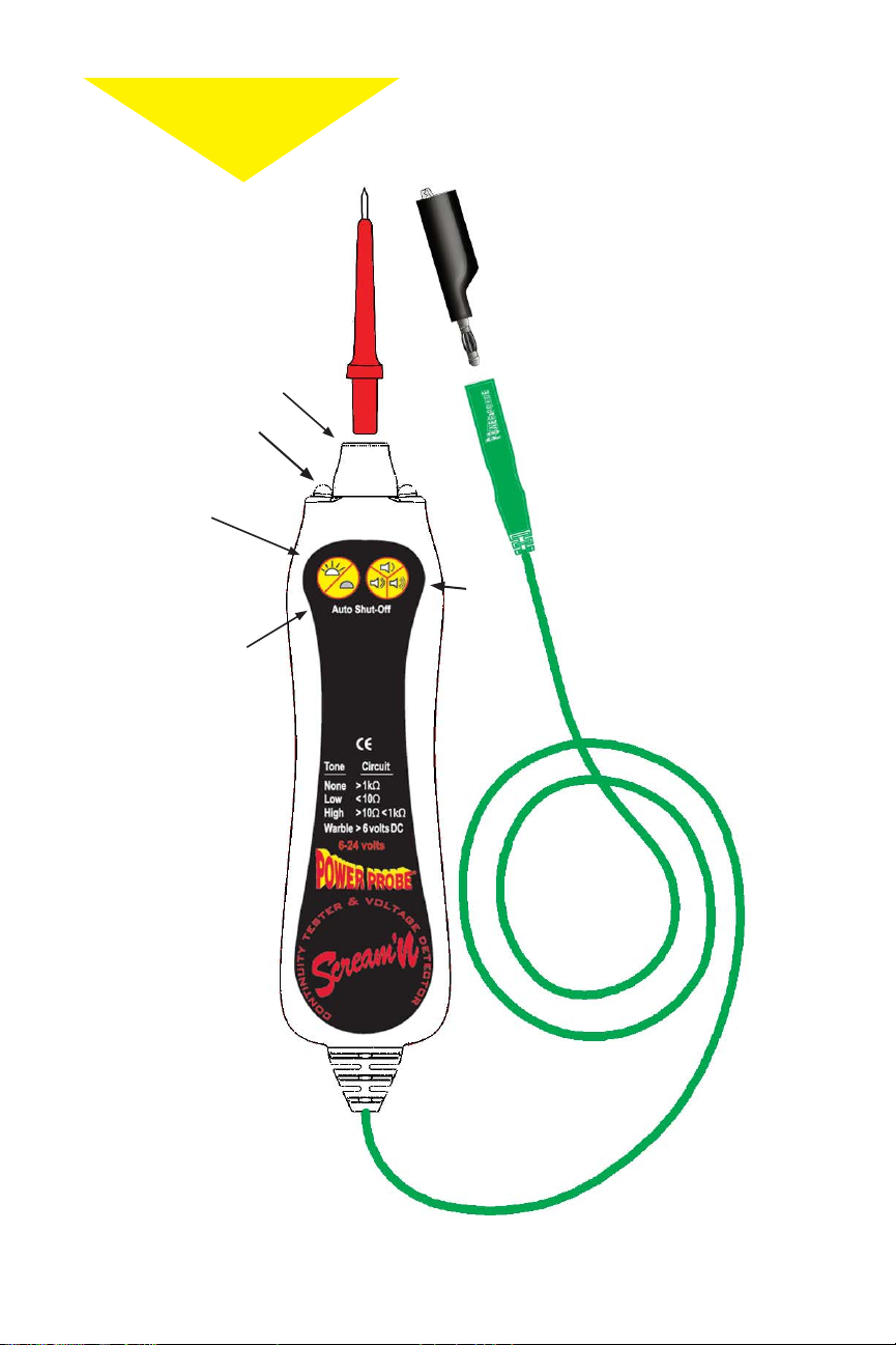
Features
Features
Probe Tip
#PN3015-RED
Gold plated
Banana Jack
Headlights
Lights
On/Off
Standard 4mm
connectors
make adding new
adapters easy...
Alligator Clip
#PN024
Gold plated
Banana Jack
(Pigtail)
Push & hold
both buttons
for 1 second
instant off
Volume
Control
(low, loud,
and
Scream’n)
10 foot Lead
3
Page 4
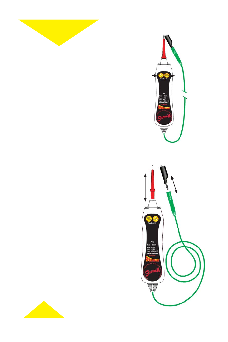
Power-On
Power-On
Power-On SCT:
There are three ways to turn the SCT on:
1. Touch the tip to the green lead
2. Press the volume button
3. Press the light on-off button
Power-Off SCT:
• The SCT will shut down automatically in 5
minutes if not used.
• To shut down the SCT manually, press and
hold both the “volume button” and the
“light on-off button” simultaneously
for 1 second.
1
3
2
Headlights
The headlights can be turned on and off by pressing the
light on-off button.
Adjustable Volume Levels
By repeatedly pressing the volume button on the SCT
you will cycle through low, medium, and Scream’N
loud audio levels. The Scream’N setting emits a signal
of 100db which can easily be heard even in the noisiest
environments.
Probe Tip & Auxiliary Leads/Adapters
The probe tip of the SCT can be removed by pulling it
outward. The front end of the SCT is a standard 4mm
Gold plated banana jack. This enables you to connect
other 4mm banana plug leads and accessories into it.
Low Battery Warning
When the battery voltage drops below the operating
range, you will hear a series of 3 beeps occurring in 5
minute intervals and if the headlights are on they will
turn off to maximize battery life. (To replace battery
see page 9)
Adapters
connected easily
4
Page 5
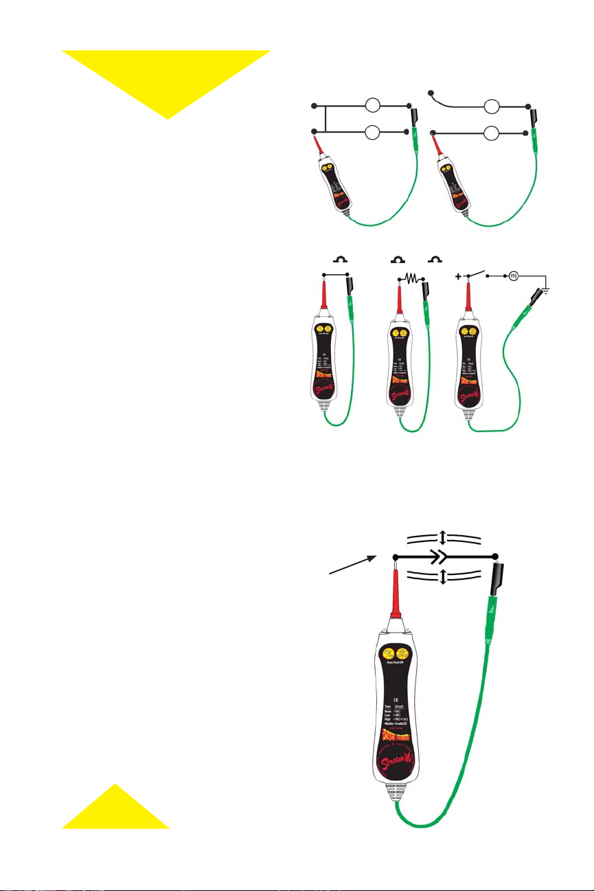
Non-isolated Circuit
Application
Application
Continuity Testing
When you plan to test continuity of a circuit it
is best to fi rst isolate the circuit. This eliminates
backfeed from parallel circuits which can lead to
a misdiagnosis.
Tone
Isolated Circuit
No Tone
Tones
The three tones of the SCT alert you to the
resistance level of a circuit.
1. LOW pitched tone indicates continuity of
a circuit under 10 ohms.
2. HIGH pitched tone indicates continuity
of a circuit over 10 ohms but under
1 K ohms.
3. WARBLE tone indicates a voltage from
6-24 volts.
Low Tone
Testing a Wire for Continuity
When checking continuity of a wire the low pitched
tone should sound indicating a good connection. If
the high pitched tone sounds the circuit resistance
is in excess of 10 ohms and may need closer examination of the connections.
Flex wire to test contact
Wiggle Test
While measuring circuits we suggest you fl ex or
wiggle the suspected wire and listen for a change
in tone. If there is a change in the tone while you
are fl exing or pulling the wire, you have a faulty
connection and should examine it closer and repair
it. A Wiggle Test is a great method to test and pinpoint both intermittent and short circuits.
<10 >10 <1k 6-24Volts
High Tone
Flex and Wiggle Test
Warble Tone
5
Page 6
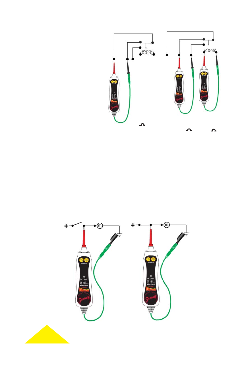
Relay Testing
The benefi t of having two tones is
that you can determine the relay coil
from the relay contacts by listening
for the high pitched tone when continuity is through the coil and the
low pitched tone when continuity is
across good closed contacts. (The
relay coil must have over 10 ohms
resistance for the high pitched tone
to sound). Typical 12V automotive
relay coil resistance ranges from 50
to a few hundred Ohms.
Low
Tone
<10
No
Tone
>1k
High
Tone
>10
Voltage Detection
(fi g.1) Connecting the SCT’s green lead to ground and then probing the tip into the positive
side of a component that is not yet activated, will sound off a steady high or low pitched tone.
(fi g.2) When the circuit is activated, a warble tone will sound off and alert you to the presence
of voltage on the circuit.
12v
(fi g.1) (fi g.2)
Steady Tone
12v
Warble Tone
6
Page 7

Checking Fuses in Vehicle
The following illustration shows fuses that are installed in the vehicle. The ignition key is in the “ON”
position. Even though the ignition key is “ON”, some fuses are under power and some are not. After
you connect the green lead of the SCT to ground, contact the probe tip to both terminals of a good fuse,
you should get identical responses. When you contact both terminals of the fuse and get a dissimilar
response, the fuse is blown.
To do this:
1. Turn the vehicle’s ignition to the “ON” position.
2. Connect the green lead of the SCT to a good ground.
3. Contact the probe tip to each of the two terminals of the fuses and observe the SCT’s response.
See the illustration below and note the difference between a Good and Bad fuse.
12V 12V
10A
Warble
Tone
Fuse is Good
Warble
Tone
Warble
Tone
Checking Fuses
Removed from Vehicle
12V
10A
Fuse is Bad
0V
Low
Tone
0V 0V
10A
Low
Tone
Fuse is Good Fuse is Bad
Low
Tone
OPEN
10A
No
Tone
0V
Low
Tone
Low Tone:
Fuse is Good
7
No Tone:
Fuse is Bad
Page 8

Diode Check
Diode Check
Forward Bias
1. Touch the green lead to the cathode side of the diode.
2. Touch the probe tip to the anode side of the diode.
3. Take note of the SCT’s response.
Reverse Bias
1. Reverse the lead and the probe tip connections
2. Touch the green lead to the anode and the probe
tip to the cathode side of the diode.
3. Take note of the SCT’s response. (Should not hear tone)
A good diode causes a tone to sound in one direction
only and nothing in the other direction.
When the probes are reversed, (or vice-versa) and you
hear a tone in both directions, or hear nothing in both
directions, the diode is either shorted or open.
(Should hear tone)
Forward Bias Reverse Bias
Cathode
Anode
Tone No Tone
Anode
See the illustration
No tone in
either direction
Open Diode
8
Tone in both
directions
Shorted Diode
Page 9

Battery Replacement
Battery Replacement
Battery Replacement
1. Unscrew the banana jack using a 3mm
or 1/8” allen hex wrench,
2. Remove the end cap,
3. Separate housing and remove batteries,
4. Install (2) new AA batteries according to
the polarity diagram.
5. Reassemble in reverse and tighten the
banana jack.
(DO NOT OVER TORQUE)
Hinged
Bottom
– +
+ –
Safety
Always wear eye protection when testing or
repairing vehicles.
Warning
A) Before opening the housing be sure the test
leads have been disconnected from all electrical
circuits.
B) Completely assemble the SCT before using to
avoid electrical shock hazard.
Front
view
Rear Inside
view
9
Page 10

Specifications
Probe tip current: ................................ 10 mA.
Open circuit voltage: .......................... 3.0 V
Volume: ...............................................100 dB @ 1ft. Max.
Low tone: ............................................ < 10 Ohms
High tone: ........................................... > 10 Ohms <1K Ohms
No tone: ..............................................> 1 K Ohm
Batteries: ............................................. (2) AA
Voltage detection ................................ 6-50 VDC
Banana Jacks ....................................... 4mm, shrouded, gold plated
Storage temperature ............................ -20°C (-4°F) to 60°C (140°F)
Operating temperature ....................... 0°C (32°F) to 50°C (122°F)
Do not exceed 24V DC.
The SCT is not intended for use in AC
circuits.
10
Page 11

GRACIAS
Gracias...
por adquirir el probador de mano Scream’N Continuity de
Power Probe (SCT). Lo hicimos
suprimir la frustración de trabajar con probadores de mano con
sonidos débiles. El volumen del SCT se ajusta hasta llegar a
sonidos muy fuertes, o para entornos de trabajo más silenciosos, también. Su nuevo SCT emite dos tonos distintos que le
permiten diferenciar entre circuitos superiores e inferiores a los
10 ohms. El SCT también emite un tono modulado en frecuencia cuando detecta más de 6 voltios.
El SCT cuenta con una toma de tipo banana de 4 mm enchapada en oro de alta calidad a ambos lados del conductor verde
asegurando la compatibilidad con todos sus enchufes, sondas
de penetración, probadores principales, etc. La toma de 4 mm
también conecta sus conductores y sondas de penetración con
un solo chasquido. Las luces delanteras incorporadas iluminan
el área de la sonda, lo que suprime la necesidad de utilizar una
linterna.
El conductor verde de 10 pies (3 metros) de largo mantiene todo
al alcance. En caso de necesitar un conductor más largo, hemos
incluido una extensión de color verde de 10 pies de largo. El
SCT funciona con dos pilas de tipo AA. El apagado automático
prologará la vida útil de la batería.
Scream’N (sonar fuerte) para
Consejo de seguridad
Antes de efectuar una prueba eléctrica, Power Probe recomienda
lea con atención este manual de instrucciones.
11
Page 12

Características
Características
Los conectores de 4 mm
estándar facilitan la adición de
Punta de la sonda
nºPN3015-RED
Toma tipo banana
enchapada en oro
Luces delanteras
Luces de
Encendido/
Apagado
nuevos adaptadores...
Pinza lagarto
nºPN024
Toma tipo banana
enchapada en oro (flexible)
Oprima ambos
botones y espere
por un segundo
para un apagado
instantáneo
Control
de volumen
(bajo, alto,
Scream’n)
Conductor
de diez pies
(3 mts) de
largo
12
Page 13

Encendido
Encendido
Encendido del SCT:
Hay tres maneras de encender el SCT:
1. Toque la punta del conductor verde
2. Oprima el botón de volumen
3. Oprima el botón de encendido y apagado
de las luces
Apagado del SCT:
• El SCT se apagará automáticamente tras cinco
minutos de inactividad.
• Para apagar el SCT en forma manual,
oprima y mantenga oprimidos los botones de
volumen y de encendido y apagado de las
luces de manera simultánea durante 1 segundo.
1
3
2
Luces delanteras
Las luces se pueden encender y apagar oprimiendo el botón
de encendido y apagado de luces.
Niveles de sonido regulables
Al oprimir varias veces el botón de volumen del SCT, pasará
por los diversos niveles de audio, bajo, medio, Scream’N y
alto. El Scream’N emitirá una señal a los 100db este sonido
se puede escuchar incluso en los entornos más ruidosos.
Punta de la sonda y conductores/adaptadores auxiliares
La punta de la sonda del SCT se puede extraer tirando hacia
afuera. El extremo frontal del SCT es una toma de tipo
banana enchapada en oro de 4mm. Esto permite conectar
otra toma tipo banana de 4mm, conductores y accesorios
al mismo.
Advertencia de batería baja
Cuando el voltaje de la batería cae por debajo del rango
de funcionamiento, escuchará una serie de tres pitidos a
intervalos de cinco minutos y si las luces se encuentran
encendidas, se apagarán para incrementar la vida de la
bateria. (para reemplazar la batería consulte la página 9).
Adaptadores
conectados fácilmente
13
Page 14

Aplicación
Aplicación
Prueba de continuidad
Cuando planifi que probar la continuidad de un circuito,
es recomendable aislar el circuito primero. Esto elimina
las indicaciones de continuidad de circuitos paralelos
que pueden conducir a diagnósticos erróneos.
Tonos
Los tres tonos del SCT lo alertan acerca del nivel
de resistencia de un circuito.
1. Un tono BAJO indica continuidad de un
circuito por debajo de los 10 ohms.
2. Un tono ALTO indica continuidad de un
circuito por sobre los 10 ohms pero por
debajo de 1 K ohms.
3. Un tono MODULADO EN FRECUENCIA
indica un voltaje de 6 a 24 voltios.
Circuito no aislado
Tono
<10 >10 <1k 6-24 voltios
Circuito aislado
Sin tono
Probar la continuidad de un cable
Al verifi car la continuidad de un cable, debe sonar el tono
bajo para indicar una buena conexión. Si se escucha el
tono alto, la resistencia del circuito excede los 10 ohms
y podría necesitar una verifi cación más exhaustiva de
las conexiones.
Flexione el cable
para probar el contacto
Prueba de ondulaciones
Mientras mide los circuitos, le sugerimos que fl exione
u ondule el cable en cuestión y que escuche si hay
cambios en el tono. Si hay un cambio en el tono
mientras fl exiona o tira del cable, se encuentra ante
una conexión defectuosa y debe examinarla con más
detenimiento y repararla. Una prueba de ondulaciones
es un excelente método para probar y determinar con
precisión tanto los circuitos intermitentes como los
cortocircuitos.
Tono bajo
Tono alto
Tono modulado en frecuencia
Tono
14
Page 15

Prueba de relé
El benefi cio de tener dos tonos es que
se puede determinar una bobina el relé a
partir de los contactos del relé mediante
la audición del tono alto cuando la
continuidad atraviesa la bobina y
el tono bajo cuando la continuidad
atraviesa contactos cerrados buenos.
(La bobina del relé debe tener una
resistencia superior a los 10 ohms para
que se escuche el tono alto).Lo comun
enla resistencia de transmission de una
bobina de 12v en el auto occila entre 50
y 100 ohms.
Tono
bajo
<10
Sin
tono
>1k
Tono
alto
>10
Detección de voltaje
(fi g.1) La conexión del conductor verde del SCT a tierra y el posterior examen de la punta en el lado
positivo de un componente que aún no está activado, hará sonar un tono estable bajo o alto.
(fi g.2) Cuando se activa el circuito, se escuchará un tono modulado de frecuencia que le alertará acerca
de la presencia de voltaje en el circuito.
(fi g.1)
12v
Tono estable
12v
(fi g.2)
Tono modulado de
frecuencia
15
Page 16

Verificación de fusibles en el vehículo
Las Siguientes ilustraciones muestran fusibles que estan instalados en el vehcíulo. La llave de ignición en
el vehículo, deberá estar en posición de encendido (on) Aún cuando la llave de ignición esta encendido
(on), algunos fusibles están bajo Corriente o energía y algunos no lo estan. Después de conectar el cable
verde del (S.C.T.) probador de continuidad a tierra, y al hacer contacto la punta del probador (S.C.T.) con
las dos terminals de un fusible en buenas condiciones, usted obtendra respuestas idénticas. Cuando se hace
contacto a las dos terminals de un fusible y se obtiene diferentes Respuestas, el fusible esta fundido.
Para hacerlo:
1. Ponga el encendido del vehículo en posición “ON”(encendido).
2. Conecte el conductor verde del SCT a buena tierra.
3. Haga contacto con la punta de la sonda en cada uno de los terminales de los fusibles u observe la
respuesta del SCT.
Observe la siguiente ilustración y note la diferencia entre un fusible Bueno y uno Malo.
12V
12V
10A
Tono modulado
en frecuencia
El fusible es bueno
Tono modulado
en frecuencia
Verificación de los
fusibles extraídos
del vehículo
12V
10A
Tono modulado
en frecuencia
0V
Tono
bajo
0V 0V
10A
Tono bajo
El fusible es bueno El fusible es maloEl fusible es malo
Tono bajo
Abierto
Sin tono
10A
0V
Tono
bajo
Tono bajo:
El fusible es bueno
16
Sin tono:
El fusible es malo
Page 17

Verifi cación
Verifi cación
de diodos
de diodos
Polarización directa
1. Toque con el conductor verde el polo positivo del diodo.
2. Toque con la punta de la sonda el polo negativo del diodo.
3. Tome nota de la respuesta del SCT
(debería escuchar un tono).
Polarización inversa
4. Invierta la sonda y el conductor. Connecciones o
contactos con la punta.
5. Toque con el conductor verde el polo negativo y con
la punta de la sonda el polo positivo.
6. Tome nota de la respuesta del SCT
un tono).
Un diodo en buen funcionamiento provoca que un tono se
escuche en una sola dirección y nada en la otra dirección.
Cuando se invierten las sondas (o vice versa) y usted
escucha un tono en ambas direcciones, o no escucha nada
en ambas direcciones, el diodo se encuentra en corto
o abierto.
(no debería escuchar
Polarización
directa
Electrodo
positivo
Electrodo negativo
Tono Sin tono
Polarización
inversa
Electrodo
positivo
Observe la ilustración.
17
Sin tono en ambas
direcciones
Diodo
abierto
Tono en ambas
direcciones
Diodo en corto
Page 18

Cambio de baterías
Cambio de baterías
Battery Replacement
1. Quite los tornillos de la toma de tipo banana
utilizando una llave allen hexagonal de 3mm
o 1/8”.
2. Retire la tapa del extremo
3. Separe la carcasa y retire las baterías
4. Coloque (2) baterías nuevas de tipo AA de
acuerdo al diagrama de polaridad.
5. Vuelva a armar en sentido inverso y ajuste
la toma de tipo banana.
(NO AJUSTE DE MÁS)
Base con
bisagras
– +
+ –
Seguridad
Siempre proteja sus ojos al probar o reparar vehículos.
Advertencia
A) Antes de abrir la carcasa, asegúrese de que los
conductores de prueba se encuentran desconectados
de todos los circuitos eléctricos.
B) Arme por completo el SCT antes de utilizarlo para
evitar el riesgo de una descarga eléctrica.
Vista
frontal
Vista interior
trasera
18
Page 19

Especificaciones
Corriente de la punta de la sonda: .............. 10 mA
Voltaje de circuito abierto: ......................... 3.0 V
Volumen: .................................................. 100 dB a 1 pie Máx
Tono bajo: .................................................. < 10 Ohms
Tono alto: .................................................. > 10 Ohms < 1K Ohms
Sin tono: ..................................................> 1 K Ohms
Baterías: .................................................. (2) AA
Detección de voltaje: .................................. 6-50 VDC
Tomas tipo banana: ..................................... 4mm, recubiertos, enchapadas en oro
Temperatura de Almacenamiento ...........-20°C (-4°F) to 60°C (140°F)
Temperatura de Operacion ..................... 0°C (32°F) to 50°C (122°F)
No exceda los 24 V DC
El SCT no debe ser utilizado con AC circuitos.
19
Page 20

8
 Loading...